EP2817723B1 - Electrically configurable option board interface - Google Patents
Electrically configurable option board interface Download PDFInfo
- Publication number
- EP2817723B1 EP2817723B1 EP13710142.4A EP13710142A EP2817723B1 EP 2817723 B1 EP2817723 B1 EP 2817723B1 EP 13710142 A EP13710142 A EP 13710142A EP 2817723 B1 EP2817723 B1 EP 2817723B1
- Authority
- EP
- European Patent Office
- Prior art keywords
- option board
- interface
- option
- host
- configurable
- Prior art date
- Legal status (The legal status is an assumption and is not a legal conclusion. Google has not performed a legal analysis and makes no representation as to the accuracy of the status listed.)
- Active
Links
- 238000000034 method Methods 0.000 claims description 23
- 238000004891 communication Methods 0.000 claims description 20
- 238000004590 computer program Methods 0.000 claims description 3
- 230000006870 function Effects 0.000 description 17
- 238000010586 diagram Methods 0.000 description 6
- 230000011664 signaling Effects 0.000 description 5
- 238000013461 design Methods 0.000 description 3
- 230000002093 peripheral effect Effects 0.000 description 3
- 238000012545 processing Methods 0.000 description 3
- 238000013459 approach Methods 0.000 description 1
- 230000003190 augmentative effect Effects 0.000 description 1
- 238000013500 data storage Methods 0.000 description 1
- 238000011161 development Methods 0.000 description 1
- 230000018109 developmental process Effects 0.000 description 1
- 230000000694 effects Effects 0.000 description 1
- 238000005516 engineering process Methods 0.000 description 1
- 238000007667 floating Methods 0.000 description 1
- 238000007726 management method Methods 0.000 description 1
- 238000004519 manufacturing process Methods 0.000 description 1
- 230000013011 mating Effects 0.000 description 1
- 230000003287 optical effect Effects 0.000 description 1
- 238000012163 sequencing technique Methods 0.000 description 1
- 238000012546 transfer Methods 0.000 description 1
Images


Classifications
-
- G—PHYSICS
- G06—COMPUTING; CALCULATING OR COUNTING
- G06F—ELECTRIC DIGITAL DATA PROCESSING
- G06F13/00—Interconnection of, or transfer of information or other signals between, memories, input/output devices or central processing units
- G06F13/38—Information transfer, e.g. on bus
- G06F13/40—Bus structure
- G06F13/4063—Device-to-bus coupling
- G06F13/4068—Electrical coupling
- G06F13/4072—Drivers or receivers
-
- G—PHYSICS
- G06—COMPUTING; CALCULATING OR COUNTING
- G06F—ELECTRIC DIGITAL DATA PROCESSING
- G06F13/00—Interconnection of, or transfer of information or other signals between, memories, input/output devices or central processing units
- G06F13/38—Information transfer, e.g. on bus
- G06F13/40—Bus structure
- G06F13/4063—Device-to-bus coupling
- G06F13/4068—Electrical coupling
Definitions
- the present invention relates to the field of electrical and electronic design, more particularly to an electrically configurable interface for a host that can be configured in hardware and/or software to accommodate various interfaces presented on option boards connected to the host.
- Option boards for augmenting functionality in systems are normally constrained to a fixed electrical interface, either dictated by the particular components used or by a particular electrical standard designed by the IEEE (e.g., Peripheral Component Interconnect - PCI) or other standards body. These constrain not only the electrical voltage levels, signaling formats, and software protocols that may be used across the interface, but also the exact type of components utilized in connection with it. Systems would gain more flexibility if option boards could be incorporated into systems that were able to adapt the interface between the system and the option board regardless of the interface configuration of the option board. Systems would be able to accommodate future developments in available options without redesigning the system interface every time a new option board became available with desirable functionality.
- IEEE Peripheral Component Interconnect - PCI
- a method comprises receiving option board identification data, determining an option board interface configuration from the board identification data, configuring host interface circuitry for option board communication; and initializing the option board.
- the method may further comprise selecting one of a predefined and a configurable input/output based on the option board identification data, selecting active signal lines to the option board and defining inputs and outputs in the configured interface.
- Configuring the interface may further comprise selecting pullups and pulldowns for each signal line, selecting a drive strength for each output, selecting the driver/receiver type for compatibility through the interface, selecting a synchronization protocol for the interface configuration, and selecting switching thresholds for the signal lines.
- the method includes the option board identification being received through a dedicated interface bus and the host interface is configured by the driver operating in the host processor.
- the method may further comprise querying the option board for its identification data and determining that the received option board identification (ID) is a valid ID.
- An alternative embodiment may be a computer program product comprising a computer readable storage medium having computer coded instructions stored therein, said instructions when executed by a processor causing an apparatus to perform receiving option board identification data, determining option board interface configuration from the board identification data, configuring host interface circuitry for option board communication, and initializing the option board.
- the program product may further comprise instructions that cause the apparatus to perform selecting active signal lines to the option board, defining inputs and outputs in the configured interface, wherein the option board identification is received through a dedicated interface bus, and wherein an interface driver for the option board is received through the dedicated interface bus and the host interface is configured by the driver operating in the host processor.
- the program product may further comprise instructions for querying the option board for its identification data, and determining that the received option board identification (ID) is a valid ID.
- Another embodiment may be an apparatus comprising at least a host logic assembly comprising a processor, a memory in communication with the processor having computer coded instructions stored therein, and electrically configurable interface circuitry; and an option board connected to the host assembly, said instructions when executed by the processor causing the apparatus to perform, receiving option board identification data, determining option board interface configuration from the board identification data, configuring host interface circuitry for option board communication, and initializing the option board.
- the apparatus may comprise instructions for querying the option board for its identification data, determining that the received option board identification (ID) is a valid ID, selecting one of a predefined and a configurable input/output based on the option board identification data, and configuring the electrically configurable interface after hot-swapping one option board for another.
- ID received option board identification
- the invention is defined according to the method of claim 1 and the apparatus of claim 5.
- a Main Logic Board (a "host") 12 and an Option board 14. It is an objective of the present invention to equip the MLB host with a configurable interface such that, despite a wide variety of interface configurations required by the Option board, the board can be connected to the MLB host and function correctly with only an invocation of the host's configuration routine controlling the configurable interface.
- MLB Main Logic Board
- Option board are intended to refer to any peripheral device or assembly that interfaces with a host logic assembly.
- the electrically configurable option board interface may comprise a host board 20 having at least three elements; a computer processing unit (CPU) 22, an Option board connection interface 24 comprising a connector, and a fixed Option board identification (ID) mechanism 26.
- the host comprises flexible electronics interface circuitry 28 enabling the host to communicate electrically with the circuitry on the Option board (not shown).
- the configurable interface circuitry 28 may comprise a Field Programmable Gate Array (FPGA) together with a configuration method to support field configuration of the FPGA through software.
- FPGA Field Programmable Gate Array
- the method may be instructions stored in a memory device 30 that would comprise a new device driver to configure the interface electronic circuitry and a protocol to communicate with the option board according to its standard requirements (e.g., PCI, VME, IEEE-488, STD-32 etc.).
- a new device driver to configure the interface electronic circuitry and a protocol to communicate with the option board according to its standard requirements (e.g., PCI, VME, IEEE-488, STD-32 etc.).
- the host board connector 24 should be configured with an electrical connector having a number of contact pins sufficient to accommodate connection to most or all of the interfaces that may be encountered on an option board.
- the option boards will normally comprise a fixed option board ID mechanism and a standard mating connector that provides the necessary connections to operate it according to its interface protocol. However, any type of connector, or multiple connectors, could be used which provide the essential connections between the host board and the option board.
- An example 64-pin connector configuration appears in Table 1.
- the Table 1 example connector configuration provides both standard and configurable interfaces. Power (pins A2-A3, A5 and B2-B3, B5) and Ground (pins A1, B1; A4; B4; A6; B8; A10; B12; A14; B16; A18; B20; A22; B23; A25; B26; A29, B29; A32, B32) connection pins are allotted. A plurality of standard interfaces are accommodated.
- a USB interface occupies pins A27-28 and B27-28.
- An Ethernet interface is provided at pins A30-31, B30-B31.
- a Secure Data Input/Output (SDIO) interface occupies pins A21, B21, B22, A23, A24, B24, B25, A26.
- a General Purpose Input/Output interface occupies pins B6, B9, B10, A11-A13, B13, B14, A15, B15, A16-A17, B17-B19, A19-A20 and is secondary to the SDIO pins as well.
- the ID mechanism that enables an option board to identify itself (and thereby its interface configuration) to the host may operate over a dedicated signal bus.
- Pins A7, B7 provide the ID signal lines (Board_ID0, Board_ID1) in the example of Table 1.
- the host MLB board interface may comprise an I2C (inter-integrated circuit) bus, with the primary function of communicating to a device on the option board storing option board ID information.
- option board type may have a unique option type ID number that the host processor can use to determine the option type, and determine and configure the communication protocol (parallel, SDIO, etc.) used for that option.
- the host board ID circuitry may also store other information such as option board serial number, etc.
- the ID interface is used by the host to obtain the option board ID information and determine which communication interface to use, and how to configure that interface. Because (in the example) pins A7, B7 are used by the MLB to receive data usable to identify the option board and configure the communication interface to the option board type, all option boards must provide the signals for that function on the same pins.
- an option board serial number or other data related to option type ID could be provided by the option board to the MLB.
- the MLB would use a lookup table, query a remote database, or execute software instructions to determine the option type ID and determine and configure the communication protocol used for that option.
- data related to option type ID could be provided by the option board using different pins, mechanical, optical, or wireless means.
- data related to option type ID could be provided to the MLB from a source other than the option board, such as a setting installed during manufacture when it is known which option board type may be installed.
- the method for supporting configuration of the flexible interface may comprise one or more of several approaches.
- An electrical connector 30 may be provided in lieu of a memory device through which an external computer may download the device driver to the CPU 22 that reconfigures the interface 28 circuitry (such as an FPGA) for communication with a new Option board.
- the method may comprise an electrically programmable read-only memory (EPROM) or simple ROM residing on the connector 30 on which is stored the device driver that reconfigures the interface 28.
- EPROM electrically programmable read-only memory
- simple ROM residing on the connector 30 on which is stored the device driver that reconfigures the interface 28.
- Interface with new option boards would simply require a new memory device to be installed on the host board to reconfigure ECOBI for the new Option board interface.
- Other possibilities exist such as downloading a device driver from a communications network) and are all within the scope of the present invention.
- the ECOBI host board comprises software running in the CPU in the form of a device manager (ECOBI DM) that performs identification of the Option board at power-on, or when a new Option board is installed or re-initialized.
- the ECOBI host board also comprises a device driver that is dispatched by the device manager (DM) to initialize the configurable interface circuitry (such as an FPGA) on the host correctly. It initializes the Option board and commences communication between the Option board and the host.
- the device driver may be resident on the host (as in an EPROM), loaded from a network or external computing device or storage dynamically, or it may even be already present on the Option board and available for loading to the host through the fixed ECOBI ID mechanism.
- Default state This is the state of the ECOBI host interface with no Option board installed, or when an Option board is installed but not yet configured, or when the Option board is not recognized by the ECOBI host. In this state, the interface must be completely benign electrically to avoid damage to both the Option board and the host interface. All signals going to the Option board should be either high impedance or in a known electrical state that is defined by the Option board interface specification to be acceptable.
- Initialization state This is the state identified by the process of initializing the ECOBI.
- the electrical interface may pass through several valid electrical states for initialization purposes, or may be in transitory states as long as they are electrically benign.
- Operation state The state in which the Option board is ready to operate.
- Option boards do not have to have the same operational state, the same number of active signals, or the same protocol managing the signal activity. What is necessary is that the state of the interface is consistent with the ECOBI device driver and the configuration of the electronic signals on the Option board.
- Interface signaling is limited only to the host interface circuitry, the interface may be configured electrically, and the signaling protocol may be any of PCI, VME, STD32, SCSI or many other standard formats. All that is required is that the host electronics be flexible enough to support the electronics across the interface.
- the ECOBI and the Option board comprise board identification (ID) circuits, which may be realized in hardware, software or a combination thereof.
- ID interface may comprise an I2C bus. This bus is dedicated to providing a means to ID the option board and other Configuration functions as needed. How the host communicates to the option board, and how the host may configure GPIO pins, is determined by the option board ID mechanism.
- Option boards may be designed for any number of optional functions that an equipment designer may wish to implement. As long as the option board interface is one that is within the capability of the ECOBI on the host MLB the option board can function within the system.
- the Option board may have generic design characteristics that make it compatible with the system MLB through the ECOBI interface.
- the Option board Interface consists of mechanical, electrical and firmware functions.
- the goal is to make the Option board interface logic and circuitry as simple as possible to reduce cost and complexity. Implementations may vary regarding what functions are implemented by mechanics, electronics or firmware, but the interface definition comprises the following:
- Fig. 3 depicts an example block diagram of the full generic assembly of the host 20 with the ECOBI 28 and an option board 32 configured to operate with it.
- the host 20 comprises a central processing unit (“processor") 22 which may be dedicated to the ECOBI 28 or may be shared with other functions in a system.
- the processor 22 is in communication with at least an electrically configurable option board interface (ECOBI) circuitry 28.
- the configurable interface circuitry may be a device such as a field programmable gate array (FPGA) or may be realized in discrete hardware circuits.
- the processor 22 is in communication with, or comprises within it, an identification control element 35 that has as a primary input the ID/configuration bus 39.
- the ID/configuration bus 39 communicates through an interface connector 24 to the ID function 38 on the option board 14.
- the communications interface between host and option board passes through the connector 24 from the configurable interface circuitry 28 on the host 20 to the option board interface element 45, which may comprise a control processor or an interface buffer.
- the host/option board interface may comprise pre-defined input/output (I/O) signal lines 41 (if the option board has a standard interface, such as PCI, USB, GPIO) or it may wholly comprise configurable signal lines 43 under the control of the host configurable interface circuitry 28.
- Power and control signals 34 also pass through the connector 24.
- a configuration element 30, which may comprise a connector, a ROM, PROM, an EPROM, or EEPROM (or other form of data storage technology), may also be part of the host if the interface configuration is to be either loaded from a memory device or downloaded to the processor 22 through a connector.
- the option board interface provides dedicated path, such as an I2C bus 39, with the primary function of communicating to a device on the option board storing option board ID information.
- Each option board will be associated with a unique option type ID number that the host processor can use to determine the option type, and to determine and configure the communication path (parallel, SDIO, etc.) used for that option.
- the board ID device might also store other information such as board serial number.
- the MLB host software/firmware may perform a board discovery/enumeration sequence (similar in function to what is done for PCI) to locate the Option Type ID on the ID/Config bus, which may be at one of several pre-determined ID addresses, and then utilize the ID information to electrically configure the configurable interface circuitry.
- the MLB software/firmware may perform a table lookup of the Option board ID to establish the proper interface configuration (number of pins used, type of electrical signaling, etc.) or the MLB software/firmware may transfer the configuration information from the Option board over the ID/Config bus. In the latter case the configuration information is stored initially on the Option board and accessed by the host.
- the MLB software/firmware may be written such that a dynamically loaded driver can be loaded to the host via the ID/Config bus from the Option board.
- Fig. 4 is a flow diagram illustration of the method sequence in which Option board ID is checked and the ECOBI configured for the interface implemented on the Option board. While Option Type ID is preferably provided by the option to the MLB, Option Board ID information could include any or all data suitable for identifying the option to communicate to the option or to configure the option.
- software/firmware accesses 44 the Option board ID over the ID interface.
- a check is performed 46 to ensure that the Option board ID is valid and supported by the host. If not, the user is notified of the failure. If the ID is valid, one of two things can happen.
- the host processor receiving the driver, would configure the host/option board interface circuitry accordingly.
- a similar process may occur if the interface driver is loaded from an external processor or communications network, or is accessed directly from a memory device on the host. Otherwise, the Option board ID is used by the processor on the host to retrieve 50 the correct interface configuration for the identified Option board. That interface configuration is then imposed 52 on the configurable interface circuitry. Once the interface is functional the host may proceed to start Option board operation 54 and initialize the Option board 56. At that point the Option board interface is ready 58 to deliver full functionality.
- selecting active signal lines to the option board defining inputs and outputs in the configured interface; selecting pullups and pulldowns for each signal line to avoid floating signal lines; selecting an input/output voltage for each signal line; selecting a drive strength for each output; selecting the driver/receiver type for compatibility through the interface; selecting a synchronization protocol for the interface configuration; and selecting switching thresholds for the signal lines.
- the GPIO lines may be routed on the MLB to support the highest data rates expected for a printer or other peripheral implementation and connected to a FPGA which can support differential, high-speed operation.
- some of the GPIO lines may be routed to the FPGA from the connector to support one or more lanes of PCI Express electrical signaling, although the FPGA and signal lines may be re-allocated to other types of electrical interfaces as needed by the Option board ID mechanism.
- Some implementations of the Option board Interface may electrically support up to 2.5 Gbps maximum over FR-4 type material if proper routing and termination are also utilized for the "GPIO" lines.
- the Option board Interface embodiment is not necessarily limited to this example, but there are obvious constraints to consider based upon the Main Logic Board routing, material, termination, interface support device(s) (FPGA, etc.) and related characteristics.
- FIG. 5 depicts an option board 14 and host main logic board 20 wherein the host 20 has available predefined I/O lines for 802.3ab, SDIO and USB standard interfaces 41. However the Option board shows that those signal lines are unused 51 on the Option board side of the connector 24.
- the working interface on the Option board side is a Parallel Port low voltage TTL (3.3 V) interface 59. Therefore, the host CPU 22, after acquiring the Option board ID (26, 35), sets up the electrically configurable interface circuitry 28 as a LVTTL 3.3V interface 59 for communication between host 20 and Option board 14.
- Fig. 6 shows a similar architectural adjustment by the host 20 where the Option board 14 presents a PCI Express interface 63using low voltage differential signal (LVDS) PCIe and LVTTL SMBus (system management bus).
- the host interface circuitry 28 has an available "pre-defined” I/O interface capability 41 that includes 802.3ab, SDIO and USB, but those lines are "unused” on the Option board side of the connector 24. Consequently, the host uses the Option board ID (26, 35) to determine the Option board's interface and configures its electrically configurable interface circuitry 28 to LVDS PCIe and LVTTL 3.3V operation 65 to match the Option board interface requirement.
- LVDS low voltage differential signal
- the host comprises at least a processor and a computer readable storage medium for storage of computer coded instructions that implement the method of configuring the Option board interface.
- Various embodiments described herein are described in the general context of method steps or processes, which may be implemented in one embodiment by a computer program product, embodied in a computer-readable storage medium, including computer-executable instructions, such as program code, executed by computers in networked environments.
- a computer-readable medium may include removable and non-removable storage devices including, but not limited to, Read Only Memory (ROM), Random Access Memory (RAM), compact discs (CDs), digital versatile discs (DVD), etc.
- program modules may include routines, programs, objects, components, data structures, etc.
- Computer-executable instructions, associated data structures, and program modules represent examples of program code for executing steps of the methods disclosed herein.
- the particular sequence of such executable instructions or associated data structures represents examples of corresponding acts for implementing the functions described in such steps or processes.
Description
- The present invention relates to the field of electrical and electronic design, more particularly to an electrically configurable interface for a host that can be configured in hardware and/or software to accommodate various interfaces presented on option boards connected to the host.
- Option boards for augmenting functionality in systems are normally constrained to a fixed electrical interface, either dictated by the particular components used or by a particular electrical standard designed by the IEEE (e.g., Peripheral Component Interconnect - PCI) or other standards body. These constrain not only the electrical voltage levels, signaling formats, and software protocols that may be used across the interface, but also the exact type of components utilized in connection with it. Systems would gain more flexibility if option boards could be incorporated into systems that were able to adapt the interface between the system and the option board regardless of the interface configuration of the option board. Systems would be able to accommodate future developments in available options without redesigning the system interface every time a new option board became available with desirable functionality.
-
US 2002/111771 A1 ,US 2010/100657 A1 ,US 2006/106 514 A1 andUS 657 2384 B1 all describe interfacing option boards to host systems. - In a first embodiment, a method is described that comprises receiving option board identification data, determining an option board interface configuration from the board identification data, configuring host interface circuitry for option board communication; and initializing the option board. The method may further comprise selecting one of a predefined and a configurable input/output based on the option board identification data, selecting active signal lines to the option board and defining inputs and outputs in the configured interface. Configuring the interface may further comprise selecting pullups and pulldowns for each signal line, selecting a drive strength for each output, selecting the driver/receiver type for compatibility through the interface, selecting a synchronization protocol for the interface configuration, and selecting switching thresholds for the signal lines. The method includes the option board identification being received through a dedicated interface bus and the host interface is configured by the driver operating in the host processor. The method may further comprise querying the option board for its identification data and determining that the received option board identification (ID) is a valid ID.
- An alternative embodiment may be a computer program product comprising a computer readable storage medium having computer coded instructions stored therein, said instructions when executed by a processor causing an apparatus to perform receiving option board identification data, determining option board interface configuration from the board identification data, configuring host interface circuitry for option board communication, and initializing the option board. The program product may further comprise instructions that cause the apparatus to perform selecting active signal lines to the option board, defining inputs and outputs in the configured interface, wherein the option board identification is received through a dedicated interface bus, and wherein an interface driver for the option board is received through the dedicated interface bus and the host interface is configured by the driver operating in the host processor. The program product may further comprise instructions for querying the option board for its identification data, and determining that the received option board identification (ID) is a valid ID.
- Another embodiment may be an apparatus comprising at least a host logic assembly comprising a processor, a memory in communication with the processor having computer coded instructions stored therein, and electrically configurable interface circuitry; and an option board connected to the host assembly, said instructions when executed by the processor causing the apparatus to perform, receiving option board identification data, determining option board interface configuration from the board identification data, configuring host interface circuitry for option board communication, and initializing the option board. The apparatus may comprise instructions for querying the option board for its identification data, determining that the received option board identification (ID) is a valid ID, selecting one of a predefined and a configurable input/output based on the option board identification data, and configuring the electrically configurable interface after hot-swapping one option board for another.
- The invention is defined according to the method of claim 1 and the apparatus of claim 5.
- Having thus described various embodiments in general terms, reference will now be made to the accompanying drawings, which are not necessarily drawn to scale, and wherein:
-
Fig. 1 is a schematic drawing of a basic host and option board assembly. -
Fig. 2 is a schematic drawing of an electrical assembly comprising an example embodiment of the configurable interface of the invention. -
Fig. 3 is block diagram of the assembly ofFig. 2 showing the inter-relationship of the components. -
Fig. 4 is a flow diagram of the process of configuring the configurable interface for operation with an option board. -
Fig. 5 is block diagram of the electrically configurable interface and option board assembly. -
Fig. 6 is block diagram of another embodiment of the electrically configurable interface and option board assembly. - Referring to
Fig. 1 , manyelectronic designs 10 can be represented in their basic form by two schematic elements, a Main Logic Board (MLB) (a "host") 12 and anOption board 14. It is an objective of the present invention to equip the MLB host with a configurable interface such that, despite a wide variety of interface configurations required by the Option board, the board can be connected to the MLB host and function correctly with only an invocation of the host's configuration routine controlling the configurable interface. (Note: in this description "option" and "option board" are intended to refer to any peripheral device or assembly that interfaces with a host logic assembly.) - Referring to
Fig. 2 , in an example embodiment the electrically configurable option board interface (ECOBI) may comprise ahost board 20 having at least three elements; a computer processing unit (CPU) 22, an Optionboard connection interface 24 comprising a connector, and a fixed Option board identification (ID)mechanism 26. To support Option boards having functional electronics that the host board should support, in addition to the ID mechanism, the host comprises flexibleelectronics interface circuitry 28 enabling the host to communicate electrically with the circuitry on the Option board (not shown). Theconfigurable interface circuitry 28 may comprise a Field Programmable Gate Array (FPGA) together with a configuration method to support field configuration of the FPGA through software. The method may be instructions stored in amemory device 30 that would comprise a new device driver to configure the interface electronic circuitry and a protocol to communicate with the option board according to its standard requirements (e.g., PCI, VME, IEEE-488, STD-32 etc.). - The
host board connector 24 should be configured with an electrical connector having a number of contact pins sufficient to accommodate connection to most or all of the interfaces that may be encountered on an option board. The option boards will normally comprise a fixed option board ID mechanism and a standard mating connector that provides the necessary connections to operate it according to its interface protocol. However, any type of connector, or multiple connectors, could be used which provide the essential connections between the host board and the option board. An example 64-pin connector configuration appears in Table 1.Table 1: Option Board Interface Pinout Pin Signal Signal Pin B1 GND GND A1 B2 24V 24V A2 B3 5V_FUSED 5V_FUSED A3 B4 GND GND A4 B5 5V (unfused) 3.3V A5 B6 PCTRLDIR / GPIO GND A6 B7 BOARD_ID1/I2C_SDA BOARD_ID0/I2C_SCK A7 B8 GND ENET_LED_NLINK A8 89 NPSELECTIN / GPIO ENET_LED_NSPEED A9 B10 NPINIT / GPIO GND A10 B11 NPSTROBE NPAUTOFD/GPIO A11 B12 GND NPFAULT/GPIO A12 B13 PSELECT/GPIO PERROR/GPIO A13 B14 PBUSY GND A14 B15 PD7 NPACK/GPIO A15 B16 GND PD6 A16 B17 PD5 PD4 A17 B18 PD3 GND A18 B19 PD1 PD2 A19 B20 GND PD0 A20 B21 SDIO1_D0 / GPIO SDIO1_CMD / GPIO A21 B22 SDIO1_D1 / GPIO GND A22 B23 GND SDIO1_CLK / GPIO A23 B24 SDIO1D2 / GPIO NRESET A24 B25 SDIO1_D3 / GPIO GND A25 B26 GND SDIO_PWR_CNTL / GPIO A26 B27 USBH_DP USB_GND A27 B28 USBH_DM USBH_OVRCUR A28 B29 GND GND A29 B30 ENET_TXP ENET_RXP A30 B31 ENET_TXN ENET_RXN A31 B32 GND GND A32 - The Table 1 example connector configuration provides both standard and configurable interfaces. Power (pins A2-A3, A5 and B2-B3, B5) and Ground (pins A1, B1; A4; B4; A6; B8; A10; B12; A14; B16; A18; B20; A22; B23; A25; B26; A29, B29; A32, B32) connection pins are allotted. A plurality of standard interfaces are accommodated. A USB interface occupies pins A27-28 and B27-28. An Ethernet interface is provided at pins A30-31, B30-B31. A Secure Data Input/Output (SDIO) interface occupies pins A21, B21, B22, A23, A24, B24, B25, A26. A General Purpose Input/Output interface occupies pins B6, B9, B10, A11-A13, B13, B14, A15, B15, A16-A17, B17-B19, A19-A20 and is secondary to the SDIO pins as well.
- The ID mechanism that enables an option board to identify itself (and thereby its interface configuration) to the host may operate over a dedicated signal bus. Pins A7, B7 provide the ID signal lines (Board_ID0, Board_ID1) in the example of Table 1. The host MLB board interface may comprise an I2C (inter-integrated circuit) bus, with the primary function of communicating to a device on the option board storing option board ID information. In one embodiment, option board type may have a unique option type ID number that the host processor can use to determine the option type, and determine and configure the communication protocol (parallel, SDIO, etc.) used for that option. The host board ID circuitry may also store other information such as option board serial number, etc. The ID interface is used by the host to obtain the option board ID information and determine which communication interface to use, and how to configure that interface. Because (in the example) pins A7, B7 are used by the MLB to receive data usable to identify the option board and configure the communication interface to the option board type, all option boards must provide the signals for that function on the same pins.
- Under another embodiment, an option board serial number or other data related to option type ID could be provided by the option board to the MLB. In this case, the MLB would use a lookup table, query a remote database, or execute software instructions to determine the option type ID and determine and configure the communication protocol used for that option. Under another embodiment, data related to option type ID could be provided by the option board using different pins, mechanical, optical, or wireless means. Under another embodiment, data related to option type ID could be provided to the MLB from a source other than the option board, such as a setting installed during manufacture when it is known which option board type may be installed.
- The method for supporting configuration of the flexible interface may comprise one or more of several approaches. An
electrical connector 30 may be provided in lieu of a memory device through which an external computer may download the device driver to theCPU 22 that reconfigures theinterface 28 circuitry (such as an FPGA) for communication with a new Option board. Alternatively, the method may comprise an electrically programmable read-only memory (EPROM) or simple ROM residing on theconnector 30 on which is stored the device driver that reconfigures theinterface 28. Interface with new option boards would simply require a new memory device to be installed on the host board to reconfigure ECOBI for the new Option board interface. Other possibilities exist (such as downloading a device driver from a communications network) and are all within the scope of the present invention. - The ECOBI host board comprises software running in the CPU in the form of a device manager (ECOBI DM) that performs identification of the Option board at power-on, or when a new Option board is installed or re-initialized. The ECOBI host board also comprises a device driver that is dispatched by the device manager (DM) to initialize the configurable interface circuitry (such as an FPGA) on the host correctly. It initializes the Option board and commences communication between the Option board and the host. The device driver may be resident on the host (as in an EPROM), loaded from a network or external computing device or storage dynamically, or it may even be already present on the Option board and available for loading to the host through the fixed ECOBI ID mechanism.
- Optionally, there are several states of the ECOBI Option board interface (and the interface may permit "hot-swapping" of Option boards) which are outlined generally below.
- Default state: This is the state of the ECOBI host interface with no Option board installed, or when an Option board is installed but not yet configured, or when the Option board is not recognized by the ECOBI host. In this state, the interface must be completely benign electrically to avoid damage to both the Option board and the host interface. All signals going to the Option board should be either high impedance or in a known electrical state that is defined by the Option board interface specification to be acceptable.
- Initialization state: This is the state identified by the process of initializing the ECOBI. The electrical interface may pass through several valid electrical states for initialization purposes, or may be in transitory states as long as they are electrically benign.
- Operation state: The state in which the Option board is ready to operate. Option boards do not have to have the same operational state, the same number of active signals, or the same protocol managing the signal activity. What is necessary is that the state of the interface is consistent with the ECOBI device driver and the configuration of the electronic signals on the Option board.
- Because the ECOBI is of flexible configuration a large number of Option boards may be developed for products of various functional capabilities. Interface signaling is limited only to the host interface circuitry, the interface may be configured electrically, and the signaling protocol may be any of PCI, VME, STD32, SCSI or many other standard formats. All that is required is that the host electronics be flexible enough to support the electronics across the interface.
- The ECOBI and the Option board comprise board identification (ID) circuits, which may be realized in hardware, software or a combination thereof. The ID interface may comprise an I2C bus. This bus is dedicated to providing a means to ID the option board and other Configuration functions as needed. How the host communicates to the option board, and how the host may configure GPIO pins, is determined by the option board ID mechanism.
- Option boards may be designed for any number of optional functions that an equipment designer may wish to implement. As long as the option board interface is one that is within the capability of the ECOBI on the host MLB the option board can function within the system. The Option board may have generic design characteristics that make it compatible with the system MLB through the ECOBI interface.
- The Option board Interface consists of mechanical, electrical and firmware functions. The goal is to make the Option board interface logic and circuitry as simple as possible to reduce cost and complexity. Implementations may vary regarding what functions are implemented by mechanics, electronics or firmware, but the interface definition comprises the following:
- Option Board ID Mechanism
- a. Option Type ID on the Option board (may be mechanical, electrical [preferred] or electro-mechanical).
- b. (Optionally) other configuration information on the Option board which may include the particular option board interface definition or may include a dynamic firmware driver that can be loaded.
- c. Option board ID Controller on the Main Logic Board (can be part of the Central Processing Unit).
- Option Interface Configuration Mechanism
- d. Configurable electrical interface circuitry on the Main Logic Board (ECOBI) - this provides a wide range of potential functional interfaces to the Option board, and may consist of CPU and/or FPGA interface circuitry.
- e. (Optionally) Semi-dedicated Electrical Interface Circuitry on the Main Logic Board.
- f. Circuitry to control Interface Power and any critical initialization sequencing - can consist of HW and FW. May optionally include hot-swap and hot-plug control.
- Option Board Driver
- g. Option Board Driver consists of Firmware that is constructed to initialize, communicate with and manage the Option Board Function. Part of the initialization process for the driver, if present, is to configure the Configurable Electrical Interface on the Main Logic Board.
- h. (Optionally) as mentioned above, the driver may be dynamically loadable from the Option board via the Option Board ID Mechanism.
-
Fig. 3 depicts an example block diagram of the full generic assembly of thehost 20 with theECOBI 28 and an option board 32 configured to operate with it. Thehost 20 comprises a central processing unit ("processor") 22 which may be dedicated to theECOBI 28 or may be shared with other functions in a system. Theprocessor 22 is in communication with at least an electrically configurable option board interface (ECOBI)circuitry 28. The configurable interface circuitry may be a device such as a field programmable gate array (FPGA) or may be realized in discrete hardware circuits. Theprocessor 22 is in communication with, or comprises within it, anidentification control element 35 that has as a primary input the ID/configuration bus 39. The ID/configuration bus 39 communicates through aninterface connector 24 to theID function 38 on theoption board 14. The communications interface between host and option board passes through theconnector 24 from theconfigurable interface circuitry 28 on thehost 20 to the optionboard interface element 45, which may comprise a control processor or an interface buffer. The host/option board interface may comprise pre-defined input/output (I/O) signal lines 41 (if the option board has a standard interface, such as PCI, USB, GPIO) or it may wholly compriseconfigurable signal lines 43 under the control of the hostconfigurable interface circuitry 28. Power andcontrol signals 34 also pass through theconnector 24. Aconfiguration element 30, which may comprise a connector, a ROM, PROM, an EPROM, or EEPROM (or other form of data storage technology), may also be part of the host if the interface configuration is to be either loaded from a memory device or downloaded to theprocessor 22 through a connector. - The option board interface provides dedicated path, such as an I2C bus 39, with the primary function of communicating to a device on the option board storing option board ID information. Each option board will be associated with a unique option type ID number that the host processor can use to determine the option type, and to determine and configure the communication path (parallel, SDIO, etc.) used for that option. The board ID device might also store other information such as board serial number.
- An example of the operation of the Option board ID function follows. The MLB host software/firmware may perform a board discovery/enumeration sequence (similar in function to what is done for PCI) to locate the Option Type ID on the ID/Config bus, which may be at one of several pre-determined ID addresses, and then utilize the ID information to electrically configure the configurable interface circuitry. The MLB software/firmware may perform a table lookup of the Option board ID to establish the proper interface configuration (number of pins used, type of electrical signaling, etc.) or the MLB software/firmware may transfer the configuration information from the Option board over the ID/Config bus. In the latter case the configuration information is stored initially on the Option board and accessed by the host. The MLB software/firmware may be written such that a dynamically loaded driver can be loaded to the host via the ID/Config bus from the Option board.
-
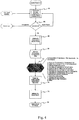
Fig. 4 is a flow diagram illustration of the method sequence in which Option board ID is checked and the ECOBI configured for the interface implemented on the Option board. While Option Type ID is preferably provided by the option to the MLB, Option Board ID information could include any or all data suitable for identifying the option to communicate to the option or to configure the option. After the Option board is connected and the system powered up, software/firmware accesses 44 the Option board ID over the ID interface. A check is performed 46 to ensure that the Option board ID is valid and supported by the host. If not, the user is notified of the failure. If the ID is valid, one of two things can happen. Optionally, if there is an Option board interface driver stored on the Option board, it can be loaded 48 over the ID bus interface into the host processor. The host processor, receiving the driver, would configure the host/option board interface circuitry accordingly. A similar process may occur if the interface driver is loaded from an external processor or communications network, or is accessed directly from a memory device on the host. Otherwise, the Option board ID is used by the processor on the host to retrieve 50 the correct interface configuration for the identified Option board. That interface configuration is then imposed 52 on the configurable interface circuitry. Once the interface is functional the host may proceed to startOption board operation 54 and initialize theOption board 56. At that point the Option board interface is ready 58 to deliver full functionality. - Among the practical configuration functions that may be performed in a configuration sequence are: selecting active signal lines to the option board; defining inputs and outputs in the configured interface; selecting pullups and pulldowns for each signal line to avoid floating signal lines; selecting an input/output voltage for each signal line; selecting a drive strength for each output; selecting the driver/receiver type for compatibility through the interface; selecting a synchronization protocol for the interface configuration; and selecting switching thresholds for the signal lines. These choices are made in the configurable interface CPU and implemented by command control signals to the configurable interface circuitry.
- A necessary consideration for interfaces where signals in GHz ranges may cross the interface is line routing and high speed performance. For full electrical flexibility, the GPIO lines may be routed on the MLB to support the highest data rates expected for a printer or other peripheral implementation and connected to a FPGA which can support differential, high-speed operation. For example, some of the GPIO lines may be routed to the FPGA from the connector to support one or more lanes of PCI Express electrical signaling, although the FPGA and signal lines may be re-allocated to other types of electrical interfaces as needed by the Option board ID mechanism. Some implementations of the Option board Interface may electrically support up to 2.5 Gbps maximum over FR-4 type material if proper routing and termination are also utilized for the "GPIO" lines. The Option board Interface embodiment is not necessarily limited to this example, but there are obvious constraints to consider based upon the Main Logic Board routing, material, termination, interface support device(s) (FPGA, etc.) and related characteristics.
- Examples of interface configurations that utilize standard interfaces are shown in
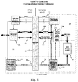
Figs. 5 and6 .Fig. 5 depicts anoption board 14 and hostmain logic board 20 wherein thehost 20 has available predefined I/O lines for 802.3ab, SDIO and USB standard interfaces 41. However the Option board shows that those signal lines are unused 51 on the Option board side of theconnector 24. The working interface on the Option board side is a Parallel Port low voltage TTL (3.3 V)interface 59. Therefore, thehost CPU 22, after acquiring the Option board ID (26, 35), sets up the electricallyconfigurable interface circuitry 28 as a LVTTL 3.3V interface 59 for communication betweenhost 20 andOption board 14. -
Fig. 6 shows a similar architectural adjustment by thehost 20 where theOption board 14 presents a PCI Express interface 63using low voltage differential signal (LVDS) PCIe and LVTTL SMBus (system management bus). Thehost interface circuitry 28 has an available "pre-defined" I/O interface capability 41 that includes 802.3ab, SDIO and USB, but those lines are "unused" on the Option board side of theconnector 24. Consequently, the host uses the Option board ID (26, 35) to determine the Option board's interface and configures its electricallyconfigurable interface circuitry 28 to LVDS PCIe and LVTTL 3.3V operation 65 to match the Option board interface requirement. - In order to provide the automated functions on the host, the host comprises at least a processor and a computer readable storage medium for storage of computer coded instructions that implement the method of configuring the Option board interface. Various embodiments described herein are described in the general context of method steps or processes, which may be implemented in one embodiment by a computer program product, embodied in a computer-readable storage medium, including computer-executable instructions, such as program code, executed by computers in networked environments. A computer-readable medium may include removable and non-removable storage devices including, but not limited to, Read Only Memory (ROM), Random Access Memory (RAM), compact discs (CDs), digital versatile discs (DVD), etc. Generally, program modules may include routines, programs, objects, components, data structures, etc. that perform particular tasks or implement particular abstract data types. Computer-executable instructions, associated data structures, and program modules represent examples of program code for executing steps of the methods disclosed herein. The particular sequence of such executable instructions or associated data structures represents examples of corresponding acts for implementing the functions described in such steps or processes.
Claims (15)
- A method comprising:receiving option board identification data;determining an option board interface configuration from the option board identification data; and characterised by:configuring host interface circuitry for option board communication based on the option board interface configuration, the host interface circuitry including a signal line having a configurable, electrical characteristic, wherein configuring the host interface circuitry comprises setting a value of the configurable electrical characteristic of the signal line based on the option board interface configuration.
- The method of claim 1, further comprising:selecting a device driver/receiver type for compatibility through the host interface circuitry.
- The method of claim 1, further comprising:selecting a synchronization protocol for the option board interface configuration.
- A computer program product comprising a computer readable storage medium having computer coded instructions stored therein, said instructions when executed by a processor causing an apparatus to perform the method as defined in any one of claims 1 to 3.
- An apparatus comprising at least a host logic assembly comprising a processor, a memory in communication with the processor having computer coded instructions stored therein, and electrically configurable interface circuitry including a signal line having a configurable electrical characteristic, the instructions when executed by the processor causing the apparatus to perform the steps of:receiving option board identification data;determining an option board interface configuration from the option board identification data; and characterised by the steps of:configuring the electrically configurable interface circuitry for option board communication based on the option board interface configuration, wherein configuring the electrically configurable interface circuitry comprises setting a value of the configurable electrical characteristic of the signal line based on the option board interface configuration.
- The apparatus of claim 5, wherein the configurable electrical characteristic of the signal line is a voltage.
- The apparatus of claim 5, further comprising instructions causing the apparatus to perform determining that the received option board identification data is valid.
- The apparatus of claim 5, further comprising instructions causing the apparatus to perform selecting one of a predefined and a configurable input/output based on the option board identification data.
- The apparatus of claim 5, further comprising instructions causing the apparatus to perform:configuring the electrically configurable interface after hot-swapping a first option board for a second option board.
- The apparatus of claim 5, further comprising an option board configured to provide option board identification data through an interface connection to the host logic assembly when power is provided.
- The apparatus of claim 5, further comprising instructions causing the apparatus to perform:selecting one of a predefined and a configurable input/output based on the option board identification data.
- The apparatus of claim 5, further comprising instructions causing the apparatus to perform:selecting active signal lines to an option board.
- The apparatus of claim 5, further comprising instructions causing the apparatus to perform:defining inputs and outputs in the electrically configurable interface.
- The apparatus of claim 5, wherein the option board identification data is received through a dedicated interface bus.
- The apparatus of claim 14, wherein an interface driver for an option board is received through the dedicated interface bus and the electrically configurable interface is configured by the driver operating in the processor.
Priority Applications (1)
| Application Number | Priority Date | Filing Date | Title |
|---|---|---|---|
| PL13710142T PL2817723T3 (en) | 2012-02-21 | 2013-02-21 | Electrically configurable option board interface |
Applications Claiming Priority (2)
| Application Number | Priority Date | Filing Date | Title |
|---|---|---|---|
| US201261601408P | 2012-02-21 | 2012-02-21 | |
| PCT/US2013/027102 WO2013126547A1 (en) | 2012-02-21 | 2013-02-21 | Electrically configurable option board interface |
Publications (2)
| Publication Number | Publication Date |
|---|---|
| EP2817723A1 EP2817723A1 (en) | 2014-12-31 |
| EP2817723B1 true EP2817723B1 (en) | 2017-06-07 |
Family
ID=47891948
Family Applications (1)
| Application Number | Title | Priority Date | Filing Date |
|---|---|---|---|
| EP13710142.4A Active EP2817723B1 (en) | 2012-02-21 | 2013-02-21 | Electrically configurable option board interface |
Country Status (5)
| Country | Link |
|---|---|
| US (1) | US10489333B2 (en) |
| EP (1) | EP2817723B1 (en) |
| CN (1) | CN104115138B (en) |
| PL (1) | PL2817723T3 (en) |
| WO (1) | WO2013126547A1 (en) |
Families Citing this family (6)
| Publication number | Priority date | Publication date | Assignee | Title |
|---|---|---|---|---|
| CN105587314A (en) * | 2014-10-23 | 2016-05-18 | 中国石油集团长城钻探工程有限公司 | Low power consumption well logging telemetry system |
| US9561646B2 (en) | 2015-03-27 | 2017-02-07 | Zih Corp. | High speed adaptive thermal printhead interface |
| US10569542B2 (en) | 2016-08-16 | 2020-02-25 | Zebra Technologies Corporation | Printhead pin configurations |
| JP6998749B2 (en) * | 2017-12-13 | 2022-01-18 | シャープ株式会社 | Information processing equipment |
| CN112905512A (en) * | 2021-02-05 | 2021-06-04 | 苏州源控电子科技有限公司 | DIO interface configuration method, device, equipment and storage medium based on Windows system |
| CN113283210B (en) * | 2021-04-14 | 2023-01-10 | 山东英信计算机技术有限公司 | Circuit assembly selecting and matching method, system and medium |
Citations (1)
| Publication number | Priority date | Publication date | Assignee | Title |
|---|---|---|---|---|
| US6572384B1 (en) * | 2001-02-08 | 2003-06-03 | 3Com Corporation | Method and apparatus for interconnecting circuit cards |
Family Cites Families (60)
| Publication number | Priority date | Publication date | Assignee | Title |
|---|---|---|---|---|
| US4500933A (en) * | 1982-04-02 | 1985-02-19 | Ampex Corporation | Universal interface unit |
| JP2832710B2 (en) | 1987-01-07 | 1998-12-09 | 沖電気工業 株式会社 | Printer |
| US5534801A (en) * | 1994-01-24 | 1996-07-09 | Advanced Micro Devices, Inc. | Apparatus and method for automatic sense and establishment of 5V and 3.3V operation |
| US5787246A (en) * | 1994-05-27 | 1998-07-28 | Microsoft Corporation | System for configuring devices for a computer system |
| US5655148A (en) * | 1994-05-27 | 1997-08-05 | Microsoft Corporation | Method for automatically configuring devices including a network adapter without manual intervention and without prior configuration information |
| JP4095680B2 (en) * | 1994-08-01 | 2008-06-04 | 富士通株式会社 | Security management method for card type storage device and card type storage device |
| US6941543B1 (en) * | 1995-05-30 | 2005-09-06 | Roy-G-Biv Corporation | Motion control system and method |
| JPH0911527A (en) | 1995-06-29 | 1997-01-14 | Tec Corp | Recording apparatus |
| US5781744A (en) * | 1995-08-25 | 1998-07-14 | Apple Computer, Inc. | Method and apparatus for ensuring safe peripheral connection |
| JPH09179802A (en) * | 1995-12-27 | 1997-07-11 | Mitsubishi Electric Corp | Multi function type pc card |
| US5736997A (en) | 1996-04-29 | 1998-04-07 | Lexmark International, Inc. | Thermal ink jet printhead driver overcurrent protection scheme |
| KR100281525B1 (en) * | 1996-11-13 | 2001-02-15 | 윤종용 | Computer system with automatic detection |
| US5892928A (en) * | 1997-05-13 | 1999-04-06 | Micron Electronics, Inc. | Method for the hot add of a network adapter on a system including a dynamically loaded adapter driver |
| US6058445A (en) * | 1997-05-13 | 2000-05-02 | Micron Electronics, Inc. | Data management method for adding or exchanging components on a running computer |
| US5951684A (en) * | 1997-12-23 | 1999-09-14 | Samsung Electronics Co., Ltd. | Method of booting a computer system with identifying a CD-ROM disk drive of the system and a method of loading a device driver |
| JP3626023B2 (en) * | 1998-10-22 | 2005-03-02 | 富士通株式会社 | Device connection state recognition method and processing apparatus having device connection state recognition function |
| US6550060B1 (en) * | 1999-04-08 | 2003-04-15 | Novadigm, Inc. | Method and system for dynamic injection of dynamic link libraries into a windowed operating system |
| US7836236B2 (en) * | 2004-02-12 | 2010-11-16 | Super Talent Electronics, Inc. | Extended secure-digital (SD) devices and hosts |
| US6470284B1 (en) | 1999-08-05 | 2002-10-22 | 02 Micro International Limited | Integrated PC card host controller for the detection and operation of a plurality of expansion cards |
| US6718274B2 (en) * | 1999-08-05 | 2004-04-06 | 2Micro International Limited | Integrated PC Card host controller for the detection and operation of a plurality of expansion cards |
| US6318846B1 (en) | 1999-08-30 | 2001-11-20 | Hewlett-Packard Company | Redundant input signal paths for an inkjet print head |
| US6505258B1 (en) * | 2000-02-29 | 2003-01-07 | Compaq Information Technologies Group, L.P. | Comprehensive interface between bios and device drivers to signal events |
| US6671748B1 (en) * | 2001-07-11 | 2003-12-30 | Advanced Micro Devices, Inc. | Method and apparatus for passing device configuration information to a shared controller |
| US7032045B2 (en) * | 2001-09-18 | 2006-04-18 | Invensys Systems, Inc. | Multi-protocol bus device |
| US7318112B2 (en) * | 2001-10-11 | 2008-01-08 | Texas Instruments Incorporated | Universal interface simulating multiple interface protocols |
| US7043585B2 (en) | 2002-03-13 | 2006-05-09 | Sun Microsystems, Inc. | Flexible system architecture with common interface for multiple system functions |
| US6895447B2 (en) * | 2002-06-06 | 2005-05-17 | Dell Products L.P. | Method and system for configuring a set of wire lines to communicate with AC or DC coupled protocols |
| US6886057B2 (en) * | 2002-06-06 | 2005-04-26 | Dell Products L.P. | Method and system for supporting multiple bus protocols on a set of wirelines |
| US7080164B2 (en) * | 2003-09-23 | 2006-07-18 | Intel Corporation | Peripheral device having a programmable identification configuration register |
| KR100524988B1 (en) * | 2003-10-02 | 2005-10-31 | 삼성전자주식회사 | Multimedia card apparatus capable of interfacing USB host and interfacing method of the same |
| US7099969B2 (en) * | 2003-11-06 | 2006-08-29 | Dell Products L.P. | Dynamic reconfiguration of PCI Express links |
| US7209987B1 (en) * | 2003-12-30 | 2007-04-24 | Eridon Corporation | Embedded system design through simplified add-on card configuration |
| US7738137B2 (en) | 2004-03-23 | 2010-06-15 | Lexmark International, Inc. | Inkjet print head synchronous serial output for data integrity |
| KR100636190B1 (en) | 2004-11-08 | 2006-10-19 | 삼성전자주식회사 | Apparatus and method for image forming by detecting thermal print head type |
| US7430465B2 (en) | 2004-11-17 | 2008-09-30 | Spx Corporation | Open-ended PC host interface for vehicle data recorder |
| JP4761530B2 (en) * | 2004-11-25 | 2011-08-31 | キヤノン株式会社 | Control board, image forming apparatus including the same, and control board management method |
| US20070233926A1 (en) * | 2006-03-10 | 2007-10-04 | Inventec Corporation | Bus width automatic adjusting method and system |
| US8103993B2 (en) * | 2006-05-24 | 2012-01-24 | International Business Machines Corporation | Structure for dynamically allocating lanes to a plurality of PCI express connectors |
| US7480757B2 (en) * | 2006-05-24 | 2009-01-20 | International Business Machines Corporation | Method for dynamically allocating lanes to a plurality of PCI Express connectors |
| US7433983B2 (en) * | 2006-09-12 | 2008-10-07 | Inventec Corporation | Method for supporting riser card by basic input/output system |
| US8010959B2 (en) * | 2006-11-29 | 2011-08-30 | Sony Ericsson Mobile Communications Ab | System and method for updating device drivers |
| US7836238B2 (en) * | 2006-12-19 | 2010-11-16 | International Business Machines Corporation | Hot-plug/remove of a new component in a running PCIe fabric |
| US20080244147A1 (en) * | 2007-03-29 | 2008-10-02 | Inventec Corporation | Device Recognition Circuit and the Method of Recognition |
| FR2915130B1 (en) | 2007-04-19 | 2010-08-20 | A P S Engineering | CONTROL MEANS, ELECTRONIC ELEMENT AND CONTROL CARD FOR OPERATING A THERMAL PRINTING MECHANISM. |
| US20090006708A1 (en) * | 2007-06-29 | 2009-01-01 | Henry Lee Teck Lim | Proportional control of pci express platforms |
| TW200910103A (en) * | 2007-08-29 | 2009-03-01 | Inventec Corp | Method for dynamically allocating link width of riser card |
| US7711870B2 (en) * | 2008-02-06 | 2010-05-04 | Panasonic Corporation | Interface detecting circuit and interface detecting method |
| EP2133209A3 (en) | 2008-06-12 | 2010-02-24 | Toshiba TEC Kabushiki Kaisha | Printing apparatus |
| US8275914B2 (en) * | 2008-10-16 | 2012-09-25 | Silicon Image, Inc. | Discovery of connections utilizing a control bus |
| CN101727419B (en) * | 2008-10-16 | 2012-08-22 | 英业达股份有限公司 | Computer capable of automatically configuring bandwidth according to types of interface expansion cards |
| CN101950252A (en) * | 2009-07-10 | 2011-01-19 | 中兴通讯股份有限公司 | USB data card self-starting method and system |
| US8140730B2 (en) * | 2009-08-12 | 2012-03-20 | International Business Machines Corporation | System reconfiguration of expansion cards |
| EP2390969A1 (en) * | 2010-05-26 | 2011-11-30 | Samsung Electronics Co., Ltd. | Connector and interface device |
| US8484387B2 (en) * | 2010-06-30 | 2013-07-09 | Silicon Image, Inc. | Detection of cable connections for electronic devices |
| JP2012213250A (en) * | 2011-03-30 | 2012-11-01 | Semiconductor Components Industries Llc | Protection circuit and input/output circuit |
| US8683087B2 (en) * | 2011-04-11 | 2014-03-25 | Fairchild Semiconductor Corporation | Mobile device auto detection apparatus and method |
| US20120280723A1 (en) * | 2011-05-05 | 2012-11-08 | Scott Gregory S | Driver with Impedance Control |
| CN102929333A (en) * | 2011-08-10 | 2013-02-13 | 鸿富锦精密工业(深圳)有限公司 | Connector combination |
| CN103722907B (en) | 2012-10-15 | 2016-08-03 | 山东新北洋信息技术股份有限公司 | Printer and control method thereof and device |
| CN104021006A (en) * | 2013-02-28 | 2014-09-03 | 慧荣科技股份有限公司 | Extensible firmware interface external display card, host system and relevant startup method |
-
2013
- 2013-02-21 WO PCT/US2013/027102 patent/WO2013126547A1/en active Application Filing
- 2013-02-21 PL PL13710142T patent/PL2817723T3/en unknown
- 2013-02-21 CN CN201380008772.3A patent/CN104115138B/en active Active
- 2013-02-21 US US13/773,161 patent/US10489333B2/en active Active
- 2013-02-21 EP EP13710142.4A patent/EP2817723B1/en active Active
Patent Citations (1)
| Publication number | Priority date | Publication date | Assignee | Title |
|---|---|---|---|---|
| US6572384B1 (en) * | 2001-02-08 | 2003-06-03 | 3Com Corporation | Method and apparatus for interconnecting circuit cards |
Also Published As
| Publication number | Publication date |
|---|---|
| US10489333B2 (en) | 2019-11-26 |
| CN104115138B (en) | 2018-01-23 |
| CN104115138A (en) | 2014-10-22 |
| PL2817723T3 (en) | 2017-11-30 |
| WO2013126547A1 (en) | 2013-08-29 |
| EP2817723A1 (en) | 2014-12-31 |
| US20130219093A1 (en) | 2013-08-22 |
Similar Documents
| Publication | Publication Date | Title |
|---|---|---|
| EP2817723B1 (en) | Electrically configurable option board interface | |
| CN110245104B (en) | Adaptive interface storage device and storage system | |
| US20070079032A1 (en) | Serial signal ordering in serial general purpose input output (SGPIO) | |
| US10162784B2 (en) | Adapter for transmitting signals | |
| CN107870882B (en) | Data protocol for managing peripheral devices | |
| KR102191237B1 (en) | Storage device with network access | |
| US8205016B2 (en) | Controller receiving a configuration command while receiving an auxiliary supply voltage | |
| US8832347B2 (en) | Automatic detection device, system and method for inter-integrated circuit and serial general purpose input/output | |
| EP2375340A1 (en) | Apparatus interoperable with backward compatible optical usb device | |
| US20240012777A1 (en) | Computer system and a computer device | |
| US8037223B2 (en) | Reconfigurable I/O card pins | |
| US20170181311A1 (en) | Microserver system | |
| CN104054064B (en) | Flexible port configuration based on interface coupling | |
| CN106294221B (en) | Electronic device and method for controlling signal strength according to mode | |
| US20040177182A1 (en) | Embedded control and monitoring of hard disk drives in an information handling system | |
| US6625144B1 (en) | Dual-use DB9 connector for RS-232 or dual-active controller communication | |
| EP3382567B1 (en) | Multiple storage devices implemented using a common connector | |
| CA2092631C (en) | Physical partitioning of logically continuous bus | |
| US10853213B2 (en) | Validation of installation of removeable computer hardware components | |
| US6829658B2 (en) | Compatible signal-to-pin connector assignments for usage with fibre channel and advanced technology attachment disk drives | |
| US8527686B2 (en) | Electronic device having multifunctional network interface port | |
| US11751332B2 (en) | Cableless interconnect | |
| US20230018849A1 (en) | Runtime configuration of chipset to support multiple i/o subsystem versions with one bios image | |
| US20200192836A1 (en) | Multiple-path thunderbolt storage apparatus and system | |
| CN110941392A (en) | Method and apparatus for emulating a remote storage device as a local storage device |
Legal Events
| Date | Code | Title | Description |
|---|---|---|---|
| PUAI | Public reference made under article 153(3) epc to a published international application that has entered the european phase |
Free format text: ORIGINAL CODE: 0009012 |
|
| 17P | Request for examination filed |
Effective date: 20140909 |
|
| AK | Designated contracting states |
Kind code of ref document: A1 Designated state(s): AL AT BE BG CH CY CZ DE DK EE ES FI FR GB GR HR HU IE IS IT LI LT LU LV MC MK MT NL NO PL PT RO RS SE SI SK SM TR |
|
| AX | Request for extension of the european patent |
Extension state: BA ME |
|
| DAX | Request for extension of the european patent (deleted) | ||
| 17Q | First examination report despatched |
Effective date: 20150925 |
|
| GRAP | Despatch of communication of intention to grant a patent |
Free format text: ORIGINAL CODE: EPIDOSNIGR1 |
|
| INTG | Intention to grant announced |
Effective date: 20170105 |
|
| GRAS | Grant fee paid |
Free format text: ORIGINAL CODE: EPIDOSNIGR3 |
|
| AK | Designated contracting states |
Kind code of ref document: B1 Designated state(s): AL AT BE BG CH CY CZ DE DK EE ES FI FR GB GR HR HU IE IS IT LI LT LU LV MC MK MT NL NO PL PT RO RS SE SI SK SM TR |
|
| REG | Reference to a national code |
Ref country code: GB Ref legal event code: FG4D |
|
| GRAA | (expected) grant |
Free format text: ORIGINAL CODE: 0009210 |
|
| REG | Reference to a national code |
Ref country code: CH Ref legal event code: EP Ref country code: AT Ref legal event code: REF Ref document number: 899703 Country of ref document: AT Kind code of ref document: T Effective date: 20170615 |
|
| REG | Reference to a national code |
Ref country code: IE Ref legal event code: FG4D |
|
| REG | Reference to a national code |
Ref country code: DE Ref legal event code: R096 Ref document number: 602013021940 Country of ref document: DE |
|
| REG | Reference to a national code |
Ref country code: NL Ref legal event code: MP Effective date: 20170607 |
|
| REG | Reference to a national code |
Ref country code: LT Ref legal event code: MG4D |
|
| PG25 | Lapsed in a contracting state [announced via postgrant information from national office to epo] |
Ref country code: LT Free format text: LAPSE BECAUSE OF FAILURE TO SUBMIT A TRANSLATION OF THE DESCRIPTION OR TO PAY THE FEE WITHIN THE PRESCRIBED TIME-LIMIT Effective date: 20170607 Ref country code: HR Free format text: LAPSE BECAUSE OF FAILURE TO SUBMIT A TRANSLATION OF THE DESCRIPTION OR TO PAY THE FEE WITHIN THE PRESCRIBED TIME-LIMIT Effective date: 20170607 Ref country code: ES Free format text: LAPSE BECAUSE OF FAILURE TO SUBMIT A TRANSLATION OF THE DESCRIPTION OR TO PAY THE FEE WITHIN THE PRESCRIBED TIME-LIMIT Effective date: 20170607 Ref country code: FI Free format text: LAPSE BECAUSE OF FAILURE TO SUBMIT A TRANSLATION OF THE DESCRIPTION OR TO PAY THE FEE WITHIN THE PRESCRIBED TIME-LIMIT Effective date: 20170607 Ref country code: NO Free format text: LAPSE BECAUSE OF FAILURE TO SUBMIT A TRANSLATION OF THE DESCRIPTION OR TO PAY THE FEE WITHIN THE PRESCRIBED TIME-LIMIT Effective date: 20170907 Ref country code: GR Free format text: LAPSE BECAUSE OF FAILURE TO SUBMIT A TRANSLATION OF THE DESCRIPTION OR TO PAY THE FEE WITHIN THE PRESCRIBED TIME-LIMIT Effective date: 20170908 |
|
| REG | Reference to a national code |
Ref country code: AT Ref legal event code: MK05 Ref document number: 899703 Country of ref document: AT Kind code of ref document: T Effective date: 20170607 |
|
| PG25 | Lapsed in a contracting state [announced via postgrant information from national office to epo] |
Ref country code: SE Free format text: LAPSE BECAUSE OF FAILURE TO SUBMIT A TRANSLATION OF THE DESCRIPTION OR TO PAY THE FEE WITHIN THE PRESCRIBED TIME-LIMIT Effective date: 20170607 Ref country code: BG Free format text: LAPSE BECAUSE OF FAILURE TO SUBMIT A TRANSLATION OF THE DESCRIPTION OR TO PAY THE FEE WITHIN THE PRESCRIBED TIME-LIMIT Effective date: 20170907 Ref country code: LV Free format text: LAPSE BECAUSE OF FAILURE TO SUBMIT A TRANSLATION OF THE DESCRIPTION OR TO PAY THE FEE WITHIN THE PRESCRIBED TIME-LIMIT Effective date: 20170607 Ref country code: NL Free format text: LAPSE BECAUSE OF FAILURE TO SUBMIT A TRANSLATION OF THE DESCRIPTION OR TO PAY THE FEE WITHIN THE PRESCRIBED TIME-LIMIT Effective date: 20170607 Ref country code: RS Free format text: LAPSE BECAUSE OF FAILURE TO SUBMIT A TRANSLATION OF THE DESCRIPTION OR TO PAY THE FEE WITHIN THE PRESCRIBED TIME-LIMIT Effective date: 20170607 |
|
| REG | Reference to a national code |
Ref country code: FR Ref legal event code: PLFP Year of fee payment: 6 |
|
| PG25 | Lapsed in a contracting state [announced via postgrant information from national office to epo] |
Ref country code: AT Free format text: LAPSE BECAUSE OF FAILURE TO SUBMIT A TRANSLATION OF THE DESCRIPTION OR TO PAY THE FEE WITHIN THE PRESCRIBED TIME-LIMIT Effective date: 20170607 Ref country code: CZ Free format text: LAPSE BECAUSE OF FAILURE TO SUBMIT A TRANSLATION OF THE DESCRIPTION OR TO PAY THE FEE WITHIN THE PRESCRIBED TIME-LIMIT Effective date: 20170607 Ref country code: EE Free format text: LAPSE BECAUSE OF FAILURE TO SUBMIT A TRANSLATION OF THE DESCRIPTION OR TO PAY THE FEE WITHIN THE PRESCRIBED TIME-LIMIT Effective date: 20170607 Ref country code: SK Free format text: LAPSE BECAUSE OF FAILURE TO SUBMIT A TRANSLATION OF THE DESCRIPTION OR TO PAY THE FEE WITHIN THE PRESCRIBED TIME-LIMIT Effective date: 20170607 Ref country code: RO Free format text: LAPSE BECAUSE OF FAILURE TO SUBMIT A TRANSLATION OF THE DESCRIPTION OR TO PAY THE FEE WITHIN THE PRESCRIBED TIME-LIMIT Effective date: 20170607 |
|
| PG25 | Lapsed in a contracting state [announced via postgrant information from national office to epo] |
Ref country code: IS Free format text: LAPSE BECAUSE OF FAILURE TO SUBMIT A TRANSLATION OF THE DESCRIPTION OR TO PAY THE FEE WITHIN THE PRESCRIBED TIME-LIMIT Effective date: 20171007 Ref country code: IT Free format text: LAPSE BECAUSE OF FAILURE TO SUBMIT A TRANSLATION OF THE DESCRIPTION OR TO PAY THE FEE WITHIN THE PRESCRIBED TIME-LIMIT Effective date: 20170607 Ref country code: SM Free format text: LAPSE BECAUSE OF FAILURE TO SUBMIT A TRANSLATION OF THE DESCRIPTION OR TO PAY THE FEE WITHIN THE PRESCRIBED TIME-LIMIT Effective date: 20170607 |
|
| REG | Reference to a national code |
Ref country code: DE Ref legal event code: R097 Ref document number: 602013021940 Country of ref document: DE |
|
| PLBE | No opposition filed within time limit |
Free format text: ORIGINAL CODE: 0009261 |
|
| STAA | Information on the status of an ep patent application or granted ep patent |
Free format text: STATUS: NO OPPOSITION FILED WITHIN TIME LIMIT |
|
| PG25 | Lapsed in a contracting state [announced via postgrant information from national office to epo] |
Ref country code: DK Free format text: LAPSE BECAUSE OF FAILURE TO SUBMIT A TRANSLATION OF THE DESCRIPTION OR TO PAY THE FEE WITHIN THE PRESCRIBED TIME-LIMIT Effective date: 20170607 |
|
| 26N | No opposition filed |
Effective date: 20180308 |
|
| PG25 | Lapsed in a contracting state [announced via postgrant information from national office to epo] |
Ref country code: SI Free format text: LAPSE BECAUSE OF FAILURE TO SUBMIT A TRANSLATION OF THE DESCRIPTION OR TO PAY THE FEE WITHIN THE PRESCRIBED TIME-LIMIT Effective date: 20170607 |
|
| REG | Reference to a national code |
Ref country code: CH Ref legal event code: PL |
|
| PG25 | Lapsed in a contracting state [announced via postgrant information from national office to epo] |
Ref country code: MC Free format text: LAPSE BECAUSE OF FAILURE TO SUBMIT A TRANSLATION OF THE DESCRIPTION OR TO PAY THE FEE WITHIN THE PRESCRIBED TIME-LIMIT Effective date: 20170607 |
|
| REG | Reference to a national code |
Ref country code: IE Ref legal event code: MM4A |
|
| PG25 | Lapsed in a contracting state [announced via postgrant information from national office to epo] |
Ref country code: LI Free format text: LAPSE BECAUSE OF NON-PAYMENT OF DUE FEES Effective date: 20180228 Ref country code: LU Free format text: LAPSE BECAUSE OF NON-PAYMENT OF DUE FEES Effective date: 20180221 Ref country code: CH Free format text: LAPSE BECAUSE OF NON-PAYMENT OF DUE FEES Effective date: 20180228 |
|
| PG25 | Lapsed in a contracting state [announced via postgrant information from national office to epo] |
Ref country code: IE Free format text: LAPSE BECAUSE OF NON-PAYMENT OF DUE FEES Effective date: 20180221 |
|
| REG | Reference to a national code |
Ref country code: GB Ref legal event code: 732E Free format text: REGISTERED BETWEEN 20190404 AND 20190410 |
|
| REG | Reference to a national code |
Ref country code: BE Ref legal event code: PD Owner name: ZEBRA TECHNOLOGIES CORPORATION; US Free format text: DETAILS ASSIGNMENT: CHANGE OF OWNER(S), FUSION; FORMER OWNER NAME: ZIH CORP. Effective date: 20190403 |
|
| REG | Reference to a national code |
Ref country code: DE Ref legal event code: R082 Ref document number: 602013021940 Country of ref document: DE Representative=s name: HASELTINE LAKE KEMPNER LLP, DE Ref country code: DE Ref legal event code: R081 Ref document number: 602013021940 Country of ref document: DE Owner name: ZEBRA TECHNOLOGIES CORPORATION, LINCOLNSHIRE, US Free format text: FORMER OWNER: ZIH CORP., LINCOLNSHIRE, US Ref country code: DE Ref legal event code: R082 Ref document number: 602013021940 Country of ref document: DE Representative=s name: HL KEMPNER PATENTANWALT, RECHTSANWALT, SOLICIT, DE |
|
| PG25 | Lapsed in a contracting state [announced via postgrant information from national office to epo] |
Ref country code: MT Free format text: LAPSE BECAUSE OF NON-PAYMENT OF DUE FEES Effective date: 20180221 |
|
| PG25 | Lapsed in a contracting state [announced via postgrant information from national office to epo] |
Ref country code: TR Free format text: LAPSE BECAUSE OF FAILURE TO SUBMIT A TRANSLATION OF THE DESCRIPTION OR TO PAY THE FEE WITHIN THE PRESCRIBED TIME-LIMIT Effective date: 20170607 |
|
| PG25 | Lapsed in a contracting state [announced via postgrant information from national office to epo] |
Ref country code: PT Free format text: LAPSE BECAUSE OF FAILURE TO SUBMIT A TRANSLATION OF THE DESCRIPTION OR TO PAY THE FEE WITHIN THE PRESCRIBED TIME-LIMIT Effective date: 20170607 Ref country code: HU Free format text: LAPSE BECAUSE OF FAILURE TO SUBMIT A TRANSLATION OF THE DESCRIPTION OR TO PAY THE FEE WITHIN THE PRESCRIBED TIME-LIMIT; INVALID AB INITIO Effective date: 20130221 |
|
| PG25 | Lapsed in a contracting state [announced via postgrant information from national office to epo] |
Ref country code: MK Free format text: LAPSE BECAUSE OF NON-PAYMENT OF DUE FEES Effective date: 20170607 Ref country code: CY Free format text: LAPSE BECAUSE OF FAILURE TO SUBMIT A TRANSLATION OF THE DESCRIPTION OR TO PAY THE FEE WITHIN THE PRESCRIBED TIME-LIMIT Effective date: 20170607 |
|
| PG25 | Lapsed in a contracting state [announced via postgrant information from national office to epo] |
Ref country code: AL Free format text: LAPSE BECAUSE OF FAILURE TO SUBMIT A TRANSLATION OF THE DESCRIPTION OR TO PAY THE FEE WITHIN THE PRESCRIBED TIME-LIMIT Effective date: 20170607 |
|
| REG | Reference to a national code |
Ref country code: DE Ref legal event code: R082 Ref document number: 602013021940 Country of ref document: DE Representative=s name: HL KEMPNER PATENTANWAELTE, SOLICITORS (ENGLAND, DE Ref country code: DE Ref legal event code: R082 Ref document number: 602013021940 Country of ref document: DE Representative=s name: HL KEMPNER PATENTANWALT, RECHTSANWALT, SOLICIT, DE |
|
| PGFP | Annual fee paid to national office [announced via postgrant information from national office to epo] |
Ref country code: FR Payment date: 20230119 Year of fee payment: 11 |
|
| PGFP | Annual fee paid to national office [announced via postgrant information from national office to epo] |
Ref country code: PL Payment date: 20230123 Year of fee payment: 11 Ref country code: GB Payment date: 20230121 Year of fee payment: 11 Ref country code: DE Payment date: 20230119 Year of fee payment: 11 Ref country code: BE Payment date: 20230119 Year of fee payment: 11 |
|
| P01 | Opt-out of the competence of the unified patent court (upc) registered |
Effective date: 20230416 |