EP1660000B1 - Dispositifs reduisant le frottement - Google Patents
Dispositifs reduisant le frottement Download PDFInfo
- Publication number
- EP1660000B1 EP1660000B1 EP04780016A EP04780016A EP1660000B1 EP 1660000 B1 EP1660000 B1 EP 1660000B1 EP 04780016 A EP04780016 A EP 04780016A EP 04780016 A EP04780016 A EP 04780016A EP 1660000 B1 EP1660000 B1 EP 1660000B1
- Authority
- EP
- European Patent Office
- Prior art keywords
- dome
- layer
- bandage
- skin contact
- contact layer
- Prior art date
- Legal status (The legal status is an assumption and is not a legal conclusion. Google has not performed a legal analysis and makes no representation as to the accuracy of the status listed.)
- Active
Links
Images


Classifications
-
- A—HUMAN NECESSITIES
- A61—MEDICAL OR VETERINARY SCIENCE; HYGIENE
- A61F—FILTERS IMPLANTABLE INTO BLOOD VESSELS; PROSTHESES; DEVICES PROVIDING PATENCY TO, OR PREVENTING COLLAPSING OF, TUBULAR STRUCTURES OF THE BODY, e.g. STENTS; ORTHOPAEDIC, NURSING OR CONTRACEPTIVE DEVICES; FOMENTATION; TREATMENT OR PROTECTION OF EYES OR EARS; BANDAGES, DRESSINGS OR ABSORBENT PADS; FIRST-AID KITS
- A61F15/00—Auxiliary appliances for wound dressings; Dispensing containers for dressings or bandages
- A61F15/008—Appliances for wound protecting, e.g. avoiding contact between wound and bandage
-
- A—HUMAN NECESSITIES
- A61—MEDICAL OR VETERINARY SCIENCE; HYGIENE
- A61F—FILTERS IMPLANTABLE INTO BLOOD VESSELS; PROSTHESES; DEVICES PROVIDING PATENCY TO, OR PREVENTING COLLAPSING OF, TUBULAR STRUCTURES OF THE BODY, e.g. STENTS; ORTHOPAEDIC, NURSING OR CONTRACEPTIVE DEVICES; FOMENTATION; TREATMENT OR PROTECTION OF EYES OR EARS; BANDAGES, DRESSINGS OR ABSORBENT PADS; FIRST-AID KITS
- A61F13/00—Bandages or dressings; Absorbent pads
- A61F13/06—Bandages or dressings; Absorbent pads specially adapted for feet or legs; Corn-pads; Corn-rings
- A61F13/064—Bandages or dressings; Absorbent pads specially adapted for feet or legs; Corn-pads; Corn-rings for feet
- A61F13/068—Bandages or dressings; Absorbent pads specially adapted for feet or legs; Corn-pads; Corn-rings for feet for the toes
-
- A—HUMAN NECESSITIES
- A61—MEDICAL OR VETERINARY SCIENCE; HYGIENE
- A61F—FILTERS IMPLANTABLE INTO BLOOD VESSELS; PROSTHESES; DEVICES PROVIDING PATENCY TO, OR PREVENTING COLLAPSING OF, TUBULAR STRUCTURES OF THE BODY, e.g. STENTS; ORTHOPAEDIC, NURSING OR CONTRACEPTIVE DEVICES; FOMENTATION; TREATMENT OR PROTECTION OF EYES OR EARS; BANDAGES, DRESSINGS OR ABSORBENT PADS; FIRST-AID KITS
- A61F13/00—Bandages or dressings; Absorbent pads
- A61F13/06—Bandages or dressings; Absorbent pads specially adapted for feet or legs; Corn-pads; Corn-rings
- A61F13/064—Bandages or dressings; Absorbent pads specially adapted for feet or legs; Corn-pads; Corn-rings for feet
- A61F13/069—Decubitus ulcer bandages
-
- A—HUMAN NECESSITIES
- A61—MEDICAL OR VETERINARY SCIENCE; HYGIENE
- A61F—FILTERS IMPLANTABLE INTO BLOOD VESSELS; PROSTHESES; DEVICES PROVIDING PATENCY TO, OR PREVENTING COLLAPSING OF, TUBULAR STRUCTURES OF THE BODY, e.g. STENTS; ORTHOPAEDIC, NURSING OR CONTRACEPTIVE DEVICES; FOMENTATION; TREATMENT OR PROTECTION OF EYES OR EARS; BANDAGES, DRESSINGS OR ABSORBENT PADS; FIRST-AID KITS
- A61F13/00—Bandages or dressings; Absorbent pads
- A61F13/10—Bandages or dressings; Absorbent pads specially adapted for fingers, hands, or arms; Finger-stalls; Nail-protectors
- A61F13/101—Bandages or dressings; Absorbent pads specially adapted for fingers, hands, or arms; Finger-stalls; Nail-protectors for the elbow, e.g. decubitus ulcer bandages
Definitions
- the present invention relates to prevention and treatment of irritation, discomfort, pain and skin breakdown resulting from shear and friction forces, and pressure against an area of skin.
- Friction and shear forces are two factors that play a significant role in causing breakdown of skin and the underlying tissues, which can lead to erythema (red spots), blisters and pressure ulcers. Friction and shear forces commonly occur at the skin-support interface, e.g. where the skin contacts another surface such as in malfitting footwear, bedding, wheelchairs, under casts and under the socket of a prosthesis (artificial limb). Skin breakdown can also occur following rubbing on skin areas contacted by undergarments, athletic equipment, and clothing, skin of hands operating industrial equipment and machinery, and in many other instances where repeated rubbing of skin occurs. The present invention relates to reducing the friction and shear forces contributing to these disabling and serious conditions.
- Scheinberg U.S. Patents Nos. 5,899,207 and 6,067,987 disclose a tissue-protective device including mutually overlying membranous layers arranged to be able to slip easily along each other at the interface between the skin and an adjacent surface, e.g. a shoe, another article of clothing or equipment pressing against or moving along the surface of skin, and internally between soft tissues in vivo, for protection from friction.
- the devices disclosed by Scheinberg are not particularly well adapted for mass production.
- a dressing or bandage which can readily be mass-produced in a form easily used by application to a person's skin or by incorporation in an article of clothing or other article that may cause friction, shearing, or pressure on the skin, either to prevent skin breakdown and reduce irritation, discomfort and pain, or to protect and enhance healing of an area of a person's skin which has already been damaged by rubbing and pressure.
- an improved device should be thin, in order to avoid creating additional pressure to the skin and underlying tissues, while greatly reducing shear and friction forces encountered by the skin.
- Such a bandage should be flexible, so that it can be easily contoured to complex curvatures of anatomical sites such as the heel, ankles and elbows. It should also be able to stretch and move with the skin during activity. A method for economically making such a dressing, bandage, or other device is also needed.
- the present invention provides a bandage that overcomes some of the shortcomings of previously available devices for protecting a person's skin from injury or irritation, and also provides a method of manufacturing such an article.
- a protective bandage includes a skin contact layer of a flexible film.
- a hollow dome of flexible film is attached to the skin contact layer and is free to move along the skin contact layer through a distance related to the height of the dome, while the side of the skin contact layer opposite the dome can be attached to a person's skin by an adhesive.
- the dome includes a dome top layer of flexible film defining the shape of the dome, and a substantially flat dome base layer of similar film material.
- the dome top layer is attached to the dome base layer, so that the dome top layer can slide along the surface of the dome base layer and the dome base layer is attached directly to the skin contact layer.
- the skin contact layer is of a flexible film material which is more elastic than the film material of the dome, and the skin contact layer extends beyond the dome to attach the dome securely to a person's skin, yet conform to and stretch and relax with the skin to which it is attached as the person moves.
- the skin contact layer is perforated, to enhance moisture and vapor transfer from the person's skin, and add to flexibility of the skin contact layer. Perforation may be omitted near a boundary between the material defining the dome and the portions of the skin contact layer that extend beyond the dome material.
- the friction reducing structure may be incorporated in an article of clothing or sports equipment against which a person's skin may be in frequent contact.
- a method of making a bandage according to the invention includes forming a flexible dome including a side wall in a flexible film, leaving the dome surrounded by a generally planar skirt, and thereafter attaching the skirt adhesively to a skin contact layer of flexible film.
- a method of manufacturing a bandage according to the present invention includes defining openings corresponding with the size of domes for the bandages in a sheet of transfer adhesive material, applying the transfer adhesive to a web of flexible film material, thereafter forming the film material within the openings to define domes, and thereafter using the adhesive layer to attach each dome to a layer of film material.
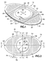
- an elliptical bandage 14 which is one preferred embodiment of the present invention includes a skin contact layer 16 of flexible film material to which a layer 18 of an adhesive material is adhered.
- the layer 18 of adhesive material is protected by an easily removable liner 20 divided into two separate halves by a cut 22 extending across the liner 20 to allow the halves of the liner 20 to be removed separately during application of the bandage 14 to a person's skin.
- one part of the liner 20 can overlap the other along the location of the cut 22, with the overlying portion including a folded-back margin flap 23 shown in broken line, to facilitate removal of the liner 20 from the skin contact layer 20 to apply the bandage.
- the bandage 14 may have a length 24 of 66.67 mm (2.625 in.) and a width 26 of 38.1 mm (1.5 in.).
- a dome 28 is centrally located on and adhesively attached to the skin contact layer 16.
- the dome 28 includes a top portion 30 and a circumferential side wall portion 32 interconnecting the top portion with the skin contact layer 16 and with intermediate portions of the bandage 14, as will be described in more detail presently.
- the dome 28 is of a thin, strong, flexible, film material, and its top portion 3b is free to move parallel with the skin contact layer 16 in any direction from a neutral position, as limited principally by the height 33 of the side wall portion 32 of the dome.
- the dome may have a diameter 29 of 25.15 mm (0.990 in.), and the top portion 30 may have a diameter 31 of 22.86 mm (0.0900 in.), for example, and the dome 28 may have a height 33 of 4.76 mm (0.1875 in.).
- the dome 28 includes a dome top layer 36 and a dome base layer 38.
- the dome base layer 38 is fastened to a first, or upper, side of the skin contact layer 16, for example being adhesively attached by a layer of adhesive material 40 that is coextensive with the dome base layer 38.
- adhesively attached should be understood to include the use of various mechanisms such as thermal fusion, ultrasonic fusion, and chemical fusion to interconnect layers of the bandage 14, as well as the use of layers of adhesive materials such as the particular pressure sensitive adhesives described herein in detail.
- the dome top layer 36 includes the top portion 30, the side wall portion 32, and a skirt portion 42 that is generally flat and which surrounds and extends radially outward in all directions from the base of the side wall portion 32.
- the skirt portion 42 is adhesively attached to the dome base layer 38 and the skin contact layer 16, as by a layer 44 of adhesive material.
- the layer 44 of adhesive material is coextensive with the skirt portion 42 but does not extend onto the side wall portion 32 or the top portion 30 of the dome 28.
- the skin contact layer 16 is larger than either the dome base layer 38 or the dome top layer 36 and preferably has an elliptical or other elongated oval shape, extending away from the dome 28 in both of a pair of opposite directions to opposite ends 48 and 50. Other shapes could also be useful for use of the bandage 14 in a particular place.
- the dome base layer 38 has a pair of opposite and parallel straight margins 52 extending transversely across the skin contact layer 16, while arcuate opposite ends 54 of the dome base layer 38 coincide with portions of the side margins 56 of the skin contact layer 16.
- the skirt portion 42 of the dome top layer 36 similarly has a pair of parallel straight margins 58 and a pair of arcuate opposite ends 60 which also coincide with portions of the side margins 56 of the skin contact layer 16.
- the straight margins 58 of the dome top layer 36 are separated from each other by a distance 72 that is somewhat greater than the distance 70 between the parallel straight margins 52 of the dome base layer 38, so that each straight margin 58 extends beyond the adjacent straight margin 52 toward a respective nearer one of the opposite ends 48 and 50 of the skin contact layer 16 on either end of the bandage 14.
- the width 70 of the dome base layer 38 between its straight margins 52 is preferably 28.6 mm (1.125 in.), while the width 72 of the dome top layer 36 may be 31.75 mm (1.25 in.), so that a portion of the skirt portion 42 attached to the skin contact layer 16 overlaps the dome base layer 38 on each side by a width 74 of about 1.6 mm (.0625 in) beyond the straight margin 52.
- the adhesive layer 44 thus attaches the dome top layer 36 both to the dome base layer 38, in an area surrounding the dome 28, and to the first or upper side of the skin contact layer 16, in narrow areas between the straight margins 52 and 58, between the dome 28 and each of the opposite ends 48 and 50 of the skin contact layer 16.
- This arrangement with the margins 58 of the skirt portion 42 overlapping beyond the margins 52 provides a smooth contour of the bandage 14 in the connection of the dome top layer 36 to the skin contact layer 16, and adds to security of the connection of the dome 28 to the skin contact layer 16.
- the top portion 30 of the dome is free from the opposing upper surface of the dome base layer 38.
- the top portion 30 thus can move parallel with and along the upper surface of the dome base layer 38 in any direction in which it is urged, to the extent that it is permitted to move by the height 33 of the side wall portion 32.
- the thin film material of the dome top layer 36 and dome base layer 38 is a flexible and strong membrane, and has a low enough coefficient of friction, when rubbing against surfaces of similar material, that there is significantly less friction between the top portion 30 of the dome and the dome base layer 38 than is likely between, for example, a person's skin and a sock pressed against the skin by the inside of a shoe.
- the top portion 30 can contact and move in any direction along the dome base layer 38 (or the skin contact layer 16, should there be no dome base layer 38), as indicated by the arrow 66.
- the dome 28 is shown in a neutral position in FIGS. 2-5 , it is shown in FIG. 1 in a collapsed condition and offset toward the end 50 of the base layer 16, as also indicated in broken line in FIG. 3 .
- the entire bandage 14 is flexible and preferably as thin as practical consistent with sufficient strength.
- the dome top layer 36 may be of polyethylene film having a thickness 62 of about 25 microns (1 mil), and the dome base layer 38 is preferably of similar film material also having a thickness 64 of about 25 microns (1 mil).
- the polyethylene is amply flexible yet strong enough to withstand the usual forces to be encountered.
- a suitable polyethylene film is available in such a thickness from Quality Extrusion of Mankato, Minnesota, as its QCE 5% EVA type A polyethylene film.
- the adhesive layers 40 and 44 respectively interconnecting the dome base layer 38 with the skin contact layer 16 and interconnecting the skirt portion 42 of the dome top layer 36 with the dome base layer 38 and the skin contact layer 16 have similar thicknesses 65 and 67 of about 25 microns (1 mil).
- one suitable transfer adhesive is a non-sensitizing medical grade, biocompatible transfer adhesive, available from Tyco Adhesives of Norwood, Massachusetts, as its "TR 2295C Medical Grade Transfer Adhesive," in the form of a coiled transfer tape, a web of adhesive material carried on a backing or liner that is relatively easily removable after the adhesive is mated with the polyethylene film material of either the dome top layer 36 or the dome base layer 38.
- a suitable material for the skin contact layer 16 is a polyurethane film having a thickness 68 of about 50 microns (2 mils).
- a polyurethane film is suitably strong and flexible and also is slightly more elastic than polyethylene, and thus is more able to conform to a person's skin as the skin stretches and relaxes during movement, than the polyethylene material preferred for the dome top layer 36 and base layer 38.
- An acceptable polyurethane film for use as the skin contact layer 16 is available from Avery Dennison Medical, of Mentor, Ohio, in such a thickness, together with a non-sensitizing, pressure sensitive, acrylic copolymer adhesive coating on one face of the film and ready for use as the adhesive layer 18, and with a silicone coated kraft paper liner already adhered to the layer 18 of adhesive material.
- a laminated material is available from Avery Dennison Medical as its MED 5042 polyurethane film.
- the bandage 14 in use thus has a thickness (excluding the liner 20) of not more than about 0.15 mm (6 mils), so as to avoid aggravating pressure dn one's skin by added bulk, as inside a shoe, for example.
- the dome base layer 38 might be omitted, although this may require a compromise with respect to either the ability of the dome 28 to move easily with respect to the skin contact layer 16, or to the ability of the skih contact layer 16 to conform to the user.
- the bandage 14 is preferably perforated to aid in transmission of vapor and moisture from the skin to which the bandage 14 may be attached. Such perforation may also enhance the flexibility of the skin contact layer and its ability to stretch.
- Arrays of perforations 80 are preferably present within the opposite end portions 48 and 50 and within the skirt portion 42, but perforations may or may not be present in the dome 28 itself. Perforations 80 are preferably separated by only a small spacing 81, such as 1.27 mm (.050 in.), and preferably in the range of 0.76 - 2.28 mm (.030-.090 in).
- An area 76 extending along each of the straight margins 58 of the dome top layer 36 is preferably free from perforations, in order to avoid interference with the stability of adhesive attachment of the dome 28 to the skin contact layer 16.
- an area 76 extending for a distance 78 of about 1.6 mm (0.0625 in) on either side of each of the straight margins 58 is left free from perforations 80 in the bandage 14 described herein above.
- the bandage 14 can be applied to a person's skin with the dome 28 aligned with a portion of the skin which otherwise might be rubbed by an article interfacing with the person's skin, such as a wheelchair, bedclothing, shoes, athletic equipment, etc.
- the dome 28 is aligned with the prominence on the outside of a person's ankle, and the top portion 30 of the dome 28 is free to move relative to the skirt 42 and the underlying dome base layer 38, while the skin contact layer 16 is securely attached to the person's skin by its adhesive layer 18.
- the flexibility and elasticity of the skin contact layer 16 permit it to conform easily to the person's ankle, and to stretch and retract itself as the person undergoes activity.
- the top portion 30 of the dome 28 is free to move in any direction, as indicated by the arrow 66, within the limitations imposed by the height of the dome 28, as previously explained.
- the length 24 of the bandage 14, or another bandage of like construction but different size, is intended to permit the opposite ends 48 and 50 of the skin contact layer 16 to overlap one another as shown in FIG. 7 when the bandage is applied to a body part such as a finger or the toe 96, in order to securely hold the bandage in place with the dome 28 located where it is needed to reduce shear and friction forces for prevention or treatment of skin breakdown.
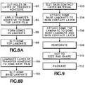
- a friction reducing bandage such as the bandage 14 is preferably made using known production equipment for working with films of plastics or other webs of material, performing a novel combination of steps.
- domes 28 are prepared by cutting openings corresponding to the size and shape of the dome 28 in a web of a transfer adhesive material to form the adhesive Layer 44.
- the web of transfer adhesive material includes in easily released protective carrier sheet or liner of coated paper on at least one side of a layer of adhesive material. Once the openings have been cut in the layer of transfer adhesive material, the transfer adhesive is adhered to one side of a web of the 1 mil.
- polyethylene film material for the dome top layer 36 forming a laminate of the dome top layer 36, the layer 44 of adhesive, and the coated paper carrier, as indicated at 84.
- These first two steps may both be accomplished using a rotary converter apparatus such as, for example, the Crusader® Converter available from Delta Industries of Minneapolis, Minnesota, or an equivalent converter apparatus capable of unwinding, separating, guiding, combining, and rewinding multiple webs from individual spools while maintaining required alignments and registrations among the various webs.
- a rotary converter apparatus such as, for example, the Crusader® Converter available from Delta Industries of Minneapolis, Minnesota, or an equivalent converter apparatus capable of unwinding, separating, guiding, combining, and rewinding multiple webs from individual spools while maintaining required alignments and registrations among the various webs.
- a dome 28 is formed in the dome top layer 36 within each opening through the layer 44 of adhesive, using heat and pressure to shape the polyethylene or other polymeric film.
- the domes 28 may be formed in sequentially produced arrays of several domes 28 produced simultaneously with each application of heat and pressure, using a machine such as is ordinarily used to form considerably thicker sheets of plastics materials to produce clam shell packaging.
- a machine such as is ordinarily used to form considerably thicker sheets of plastics materials to produce clam shell packaging.
- One such machine which has been found suitable for forming the very thin polyethylene film of the dome top layer 36 to produce an array of domes 28 and their skirts 42 for twenty-seven bandages 14 in each heating and pressing cycle is available from Preco Industries, Inc. of Lenexa, Kansas, as its ConvertaFormTM forming system.
- This machine utilizes appropriate heated molds and dies in an automated air pressure forming system and can handle a forming area up to about 330 x 420 mm (13 inches by 16.5 inches) with each cycle.
- such domes are prepared using a tool to produce a dome initially having a height 33 of 0.250 in. (0.635 cm), including a flat top portion 30 with a diameter 31 of 0.900 in. (2.29 cm) interconnected with the side wall portion 32 by a radiused transition zone 92 whose radius 94 is preferably 0.125 in (0.318 cm). but which may satisfactorily be within the range of 1.27-3.81 mm (0.050 - 0.150 in.).
- the polyethylene material typically retracts slightly so that the dome height 33 is ultimately about 4.76 mm (0.1875 in).
- the domes 28 are thus left free to move in any direction along the dome base layer 38, within the limitations established by the height 34 of the side wall portion 32, the extent of the transition zone 92, and the flexibility of the material of the dome top layer 36.
- top portion 30 may also be formed to extend, for example, in the form of a portion of a spherical surface without adversely affecting the properties of the completed bandage 14.
- the laminate is slit, as mentioned at 88, to form a continuous web of the laminate of the dome top layer 36 with domes 28 formed therein, the adhesive layer 44, and its cover sheet (not shown), bounded by the straight margins 58, and with the width 72 previously mentioned.
- a layer of transfer adhesive to form adhesive layer 40 is laminated to a web of film material to be used as the dome base layer 38 as shown at 100. As shown at 102 the laminate of the dome base layer film and transfer adhesive is slit to form straight margins 52 separated by the required width 70.
- the bandages are assembled using a rotary converter such as the one described previously.
- a web of the required material for the skin contact layer 16 is slit to a width such as about 76 mm (3 in), wide enough to encompass the length 24 of the bandage 14, as indicated at 103.
- the dome base laminate of layers 36 and 40 formed as mentioned above at 102 is applied to the skin contact layer 16 by appropriately removing any carrier or liner from the layer 40 of transfer adhesive material, and the dome base layer 38 is placed on the skin contact layer 16 and fastened to it by the action of the adhesive layer 40, as shown at 104.
- the dome base layer 38 is aligned with a middle part of the skin contact layer web, so that its straight margins 52 face toward the sides of the slit web of skin contact layer material and are parallel with the length of that web of skin contact layer material.
- the previously fabricated dome top laminate of domes 28, skirt portions 42, and adhesive layer 44 is attached to the dome base layer 38 and the skin contact layer 36 in proper alignment with the dome base layer 38, so that the straight margins 58 of the dome top layer 36 are located outside the straight margins 52 of the dome base layer and parallel with them.
- the skirt portion 42 of the dome top layer 36 is thus attached by the adhesive layer 44 both to the dome base layer 38 and to the carrier layer 16, where the margins 58 of the dome top layer 36 extend beyond the straight margins 52 of the dome base layer 38.
- each bandage 14 is appropriately perforated, 108 preferably by a sonic perforating machine associated with the converter.
- a suitable sonic perforator is available from Branson Ultrasonic Corporation, of Danbury, Connecticut.
- the individual bandages 14 are then cut to finished size and shape, and the cut 22 is made in the liner 20, as shown at 110, preferably by die cutting, using the rotary converter.
- the liner 20 can be removed and replaced by a combination of liner portions of which one includes a margin folded back as a flap 23, shown in broken line in FIG. 1 , before the individual bandages 14 are cut to finished size and shape.
- the bandages 14 are then released from the surrounding areas of the laminated webs of skin contact layer 16, dome base layer 38, and dome top layer 36, and as noted at 112 the individual bandages are appropriately packaged.
- a bandage 114 is of similar construction to the bandage 14, but is of a different shape, resembling a figure-of-eight having a pair of enlarged end portions 116 and 118 and a narrow waist portion 120.
- a dome 122 of the bandage 114 also has a pair of convexly arcuate end portions 124 and 126 that are interconnected by a narrower waist portion 128.
- Such a bandage 114 is intended principally for use to protect convex portions of one's anatomy, such as elbows, heels, fingers, and toes, and can be made in a range of sizes, with a preferred overall length 130 of 57 mm (2.25 in.) and an overall width 132 of 31.75 mm (1.25 in.), with a waist width 134 of 22.23 mm (0.875 in.).
- the overall length 130 and overall width 132 could be varied within a range of at least ⁇ 1/2 in (1.27 cm).
- the dome 122 is significantly shorter than the overall length 130 to provide ample adhesive-carrying area in the end portions 124 and 126 of the skin contact layer, to attach the bandage securely to a person's skin.
- the dome 122 thus has a preferred overall length 136 of about 35 mm (1.375 in.) and an overall width 138 of about 12.7 mm (0.5 in.), although both of these dimensions could be varied within a range of at least ⁇ 6.3 mm (0.25 in.).
- the height of such a dome could be within the range of 4-6mm. (0.18 - 0.25 in.).
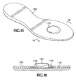
- a bandage 144 has an oval shape and may be elliptical, for example, with an overall length 146 of 108 mm (4.25 in.) and an overall width 148 of 76.2 mm (3 in.), both of which could be varied by as much as ⁇ 19 mm ( ⁇ 0.75 in.).
- a centrally located circular dome 150 whose diameter is preferably about 57.2 mm (2.25 in.), or could be varied within ⁇ 9.5 mm ( ⁇ 3/8 in.) of that size, is provided to correspond with the length 146 and width 148 of the bandage 144.
- the bandage 144 has an amply wide skirt portion 152 surrounding the dome 150 and also has some extension of a suitably flexible and elastic skin contact layer at each of the ends 154 and 156.
- the larger size of the bandage 144 by comparison with the previously described bandages 14 and 114 makes the bandage 144 more appropriate for use in prevention and treatment of pressure ulcers.
- the bandage 144 is preferably manufactured of film materials and adhesives such as those described above, or of variations of those materials having a different moisture vapor transference rate. Such a bandage could be used in locations such as a person's sacrum (lower back), greater trochanter (hip), gluteus maximus (buttocks), heels, or elbows.
- the bandage could also be produced with the dome and skin contact layer in other shapes to be used in other particular applications, without departing from the invention.
- the size of the bandage 14 could also be varied, keeping the same proportions to provide a bandage 14 whose size is, for example, 20 percent larger or 40 percent larger than previously mentioned, in order to protect an area of a patient's skin with an appropriately large bandage.
- a bandage 160 shown in FIG. 12 may be utilized.
- the bandage 160 may generally be similar to the bandage 14, in an area 161 corresponding generally in size and shape to the dome, and optionally including the area 163 of the skirt portion of the dome top layer and the area of the dome base layer, the adhesive carrying lower or second side of the skin contact layer may be left without a layer of adhesive, or may be provided with a layer 162 of an adhesive translucent, flexible hydrocolloid material.
- Such a hydrocolloid material once the liner 164 has been removed from the bandage, is placed in contact with the patient's sore or abraded skin or other wound and can absorb wound exudate, promote a moist wound-healing environment, and provide cushioning.
- a hydrocolloid material is available, for example, from Avery Dennison Medical, of Mentor, Ohio, as its MED 2190H, an 18 mil (0.457 mm) hydrocolloid, low peel force, transfer adhesive tape. Similar material may also be used in various thicknesses in a range of 10 to 50 mils (0.254 to 1.27 mm) for various applications.
- a device embodying the present invention could also be applied to a surface of a device or an article pf clothing, rather than to the user's skin.
- a layer of a suitable material corresponding to the skin-contact layer 16 could be attached by sewing, or other bonding technique, i.e., heat or ultrasound, to the inside of a user's apparel, i.e., underwear, sock or shoe. It could also be attached to the inside of a shoulder pad, elbow pad or backpack strap, etc., for use in athletic or recreational activities.
- friction reducing devices embodying the present invention could be incorporated into many articles during original manufacture of such articles, such as hospital mattress covers, wheelchair cushions, bicycle seats, shoe inserts, removable heel counters for shoes, other locations in the interior of shoes, socks, undergarments, straps for undergarments, and backpacks.
- FIGS. 13 and 14 show a removable heel counter 166 for a sports shoe, incorporating a friction reducing device 168 according to the present invention in which a dome 170 is exposed on an inward-facing surface 172 of the removable heel counter 166.
- the friction reducing device 168 may also include a dome base layer 173, between the dome 170 and a dome supporting layer 174.
- the dome base layer 173 would be attached to the dome supporting layer 174 and be of material over which the dome 170 can glide freely.
- the friction reducing device 168 thus incorporates structures capable of performing the function of a friction reducing bandage 14, as described above, in the supporting structure of a heel counter 166, which may be a removable shoe accessory or a permanent part of a shoe.
- the dome supporting layer 174 of such a friction reducing device 168 corresponds to the skin contact layer 16 of the bandage shown in FIGS. 1-5 and may be of a thicker material, and may be thermally laminated into the structure of the heel counter 166 itself. If a dome base layer 173 is not included, the dome supporting layer 174 should be of material that would not interfere with the gliding motion of the dome top layer 170.
- the supporting layer 174 is preferably of a thicker film or may be of a durable, sturdy textile fabric, such as a woven cloth or knitted textile material, or of a different plastic such as a film or sheet of polyamide or polyester compatible with the adjacent material of the rest of the heel counter 166, since greater durability than for a bandage is preferred.
- the supporting layer 174 could also be of a plastic material such as polyurethane, suitable to be molded into, or inserted between other layers of the structure of the article concerned, to provide a secure incorporation of a friction reducing device 182 according to the present invention.
- the friction reducing device 182 also includes a dome 170 which is carried by a supporting layer 174 and exposed to be contacted by the user's foot to function in the same way as the dome 28.
- the friction reducing domes 170 can be manufactured in generally the same fashion as that described above with respect to the bandage 14, with modifications as necessary to the supporting layer 174 depending on the article in which the friction reducing device is being incorporated.
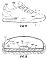
- a shoe 188 may incorporate friction-reducing devices 190 each including an integral dome 192 that functions in generally the same way as the dome 28.
- the friction reducing device 190 may be located in a permanently included heel counter portion of the shoe, in a heel collar, in the permanent insole, or at another critical place in the upper of such a shoe 188.
- a dome top layer 194 and dome base layer 196 may be made of a flexible material of greater strength than the 25 microns-thick polyethylene film used as the dome top layer 36 of the bandage 14 described above.
- a polyethylene film material having a greater thickness 198, in the range of 25 microns to 1.525 mm (1-60 mils) would be satisfactory.
- polyethylene another polymeric material such as a polyester film or a soft and closely woven or knitted textile fabric might be used, although it might require the use of a small amount of a lubricant between the dome top layer 194 and the dome base layer 196.
- the top layer 194 and bottom layer 196 are appropriately formed and interconnected portions of the textile fabric, plastic-impregnated fabric, or plastic film of which the shoe 188 or other article is constructed, thin enough to be easily flexible, and lubricated as necessary to be able to slip readily along each other.
- Such formation and interconnection of the layers of material to form the domes 192 is performed as part of the process of assembling the article including the domes 192.
Claims (43)
- Un pansement de protection (14, 114, 144, 160) se composant de ce qui suit :(a) une couche de contact cutané (16) de film flexible ayant des premier et deuxième côtés opposés ;(b) un dôme creux rétractable (28, 122, 150) de film flexible fixé à et recouvrant une partie du premier côté de la couche de contact cutané (16), le dôme creux (28, 122, 150) ayant une partie de paroi latérale (32), une hauteur (33) et une partie supérieure (30), la couche de contact cutané (16) s'étendant au-dessous de tout le dôme (28, 122, 150), la partie supérieure (30) pouvant se déplacer librement le long du premier côté de la couche de contact cutané (16) sur une distance liée à la hauteur (33) ; et(c) le deuxième côté étant fixé de manière adhésive à une surface destinée à être protégée.
- Un pansement (14, 114, 144, 160) selon la revendication 1, comprenant également une couche (18) de matériau adhésif portée sur au moins une partie du deuxième côté de la couche de contact cutané (16).
- Un pansement (14, 114, 144, 160) selon la revendication 2, dans lequel la couche (18) de matériau adhésif possède la même étendue que le deuxième côté de la couche de contact cutané (16).
- Un pansement (14, 114, 144, 160) selon la revendication 2, dans lequel la couche (18) de matériau adhésif est absente d'une zone du deuxième côté de la couche de contact cutané (16) opposée et alignée sur le dôme (28, 122, 150).
- Un pansement (14, 114, 144, 160) selon n'importe laquelle des revendications précédentes présentant un ensemble de perforations (80) traversant la couche de contact cutané (16) à l'extérieur de la partie sur laquelle le dôme (28, 122, 150) s'étend.
- Un pansement (14, 114, 144, 160) selon la revendication 5, dans lequel la dimension la plus grande des perforations (80) va de 0,25 mm à 1,27 mm.
- Un pansement (14, 114, 144, 160) selon la revendication 5, dans lequel les perforations (80) sont espacées les unes des autres dans l'ensemble de perforations par une distance allant de 0,76 mm à 2,29 mm.
- Un pansement (14, 114, 144, 160) selon n'importe laquelle des revendications précédentes dans lequel le dôme creux (28, 122, 150) comprend une couche supérieure de dôme (36) de film flexible, la couche supérieure de dôme (36) comprenant une partie périphérique (42, 152) entourant le dôme (28, 122, 150) et en dépassant et fixée de manière adhésive à la couche de contact cutané (16).
- Un pansement (14, 114, 144, 160) selon la revendication 8, comprenant une couche (44) de matériau adhésif conforme à la partie périphérique (42, 152) et attachant la partie périphérique (42, 152) à la couche de contact cutané (16).
- Un pansement (14, 114, 144, 160) selon les revendications 8 ou 9, dans lequel la couche supérieure de dôme (36) comprend la partie de paroi latérale (32) allant de la partie périphérique (42, 152) à la partie supérieure (30).
- Un pansement (14, 114, 144, 160) selon n'importe laquelle des revendications 8 à 10, dans lequel la partie supérieure du dôme (28, 122, 150) est plate et s'étend de manière parallèle à la partie périphérique (42, 152) de la couche supérieure de dôme (36).
- Un pansement (14, 114, 144, 160) selon les revendications 10 ou 11, comprenant une partie de transition arquée (92) reliant la paroi latérale (32) à la partie supérieure (30) du dôme (28, 122, 150).
- Un pansement (14, 114, 144, 160) selon n'importe laquelle des revendications 8 à 12, dans lequel la couche de contact cutané (16) est plus grande que la couche supérieure de dôme (36).
- Un pansement (14, 114, 144, 160) selon n'importe laquelle des revendications 8 à 13, dans lequel la couche de contact cutané (16) est allongée et va au-delà de la couche supérieure de dôme (36) dans deux directions opposées.
- Un pansement (14, 114, 144, 160) selon n'importe laquelle des revendications 8 à 12, dans lequel la partie périphérique (42, 152) possède une marge (58) comprenant une partie droite, la couche de contact cutané (16) s'étend dans une direction opposée à la couche supérieure de dôme (36) au-delà de la partie droite, et le pansement (14, 114, 144, 160) comporte un ensemble de perforations traversant la couche de contact cutané (16), mais dans lequel le pansement (14, 114, 144, 160) est dépourvu de perforations sur une zone s'étendant sur une distance prédéterminée à partir de la partie droite de la marge (58).
- Un pansement (14, 114, 144, 160) selon la revendication 15, dans lequel certaines des perforations traversent la partie périphérique (42, 152).
- Un pansement (14, 114, 144, 160) selon n'importe laquelle des revendications précédentes, dans lequel la hauteur (33) du dôme (28, 122, 150) est d'au moins 4 mm.
- Un pansement (14, 114, 144, 160) selon n'importe laquelle des revendications précédentes, dans lequel le pansement (14, 114, 144, 160) possède une épaisseur non supérieure à 0,153 mm lorsque le dôme (28, 122, 150) est rentré.
- Un pansement (14, 114, 144, 160) selon n'importe laquelle des revendications 8 à 16, dans lequel la couche supérieure de dôme (36) est plus mince que la couche de contact cutané (16).
- Un pansement (14, 114, 144, 160) selon n'importe laquelle des revendications 8 à 16 et 19, dans lequel la couche de contact cutané (16) est constituée d'un matériau plus élastique que la couche supérieure de dôme (36).
- Un pansement (14, 114, 144, 160) selon n'importe laquelle des revendications 8 à 16, 19 et 20, dans lequel le film flexible de la couche supérieure de dôme (36) est suffisamment perméable au gaz pour que le dôme (28, 122, 150) soit sensiblement rentré lorsque le pansement (14, 114, 144, 160) est utilisé.
- Un pansement (14, 114, 144, 160) selon n'importe laquelle des revendications précédentes, dans lequel le dôme (28, 122, 150) est circulaire.
- Un pansement (14, 114, 144, 160) selon n'importe laquelle des revendications précédentes, dans lequel la couche de contact cutané (16) est ovale.
- Un pansement (14, 114, 144, 160) selon n'importe laquelle des revendications précédentes comprenant un lubrifiant dans le dôme (28, 122, 150) et en contact avec la partie supérieure du dôme (30).
- Un pansement (160) selon n'importe laquelle des revendications précédentes comprenant une couche (162) de matériau hydrocolloïde couvrant une partie du deuxième côté de la couche de contact cutané.
- Un pansement (14, 114, 144, 160) selon n'importe laquelle des revendications précédentes, dans lequel le dôme (28, 122, 150) est sensiblement rentré lorsque le pansement (14, 114, 144, 160) est utilisé.
- En combinaison avec un élément d'habillement (188) destiné à être utilisé par une personne, un dispositif réduisant le frottement (166), se composant de ce qui suit :(a) une couche de support (174) de matériau flexible ayant des premier et deuxième côtés opposés ;(b) un dôme creux (170) de matériau sous forme de film flexible fixé à et recouvrant une partie du premier côté de la couche de support (174), le dôme creux (170) ayant une hauteur et une partie supérieure, et la couche de support (174) s'étendant au-dessous de tout le dôme (170), le dôme creux (170) étant rétractable et la partie supérieure étant libre de se déplacer le long de et en contact contre le premier côté de la couche de support (174) sur une distance liée à la hauteur ; et(c) le deuxième côté étant fixé à une partie de l'élément d'habillement de telle sorte que le dôme creux (170) soit exposé vers une surface destinée à être protégée.
- Une combinaison selon la revendication 27, dans laquelle l'élément d'habillement est une chaussure (188).
- Une combinaison selon les revendications 27 ou 28, dans laquelle le matériau flexible du dôme (170) comprend un film polymérique.
- Une combinaison selon n'importe laquelle des revendications 27 à 29, dans laquelle le matériau flexible du dôme (170) comprend une matière textile.
- Un accessoire amovible (166, 180) pour un élément d'habillement (188), l'accessoire comprenant un dispositif de réduction du frottement (168, 182, 190) se composant de ce qui suit :(a) une couche de support (174) de matériau flexible ayant des premier et deuxième côtés opposés ;(b) un dôme rétractable creux (170, 192) de matériau sous forme de film flexible fixé à et s'étendant au-dessus d'une partie du premier côté de la couche de support (174), le dôme creux (170, 192) ayant une hauteur et une partie supérieure, et la couche de support (174) s'étendant au-dessous de tout le dôme (170, 192), la partie supérieure étant libre de se déplacer le long du premier côté de la couche de support (174) sur une distance liée à la hauteur ; et(c) le deuxième côté étant fixé à une partie de l'accessoire amovible (166, 180) de telle sorte que le dôme creux (170, 192) soit exposé à une surface destinée à être protégée lorsque l'accessoire (166, 180) est utilisé.
- Un accessoire amovible (166) selon la revendication 31 comprenant un contrefort (166) pour une chaussure (188).
- Un accessoire amovible (180) selon la revendication 31 comprenant une semelle intérieure (180) pour une chaussure.
- Un accessoire amovible (166, 180) selon n'importe laquelle des revendications 31 à 33, dans lequel le matériau flexible du dôme creux (170, 192) comprend un film polymérique.
- Un accessoire amovible (166, 180) selon n'importe laquelle des revendications 31 à 33, dans lequel le matériau flexible du dôme creux (170, 192) comprend une matière textile.
- Un procédé de fabrication d'un pansement (14, 114, 144, 160), se composant des opérations suivantes :(a) former un film flexible de façon à obtenir un dôme flexible rétractable (28, 122, 150) ayant une hauteur (33) et comportant une paroi latérale flexible (32) et une partie supérieure flexible (30), en laissant le dôme (28, 122, 150) entouré par une partie périphérique généralement plane (42, 152) de film flexible s'étendant radialement vers l'extérieur à partir du dôme (28, 122, 150) ; et(b) fixer ensuite la partie périphérique (42, 152) de manière adhésive à une couche de contact cutané (16) généralement plane de film flexible s'étendant au-dessous de tout le dôme (28, 122, 150), de façon à ce que la partie supérieure (30) soit rétractable en cas de contact avec et puisse se déplacer le long de la couche de contact cutané (16) sur une distance liée à la hauteur (33).
- Un procédé selon la revendication 36, dans lequel l'opération consistant à fixer la partie périphérique (42, 152) à la couche de contact cutané (16) suppose de former une ouverture correspondant au dôme (28, 122, 150) dans une couche (44) d'adhésif de transfert, puis de fixer la couche d'adhésif de transfert (44) à la partie périphérique (42, 152) et à la couche de contact cutané (16).
- Un procédé selon la revendication 36 supposant également de fixer de manière adhésive une couche de base de dôme (38) généralement plane de film flexible sur la couche de contact cutané (16) à un endroit de façon à s'étendre au moins au-dessous de tout le dôme (28, 122, 150), avant l'opération consistant à fixer la partie périphérique (42, 152) à la couche de contact cutané (16), et dans lequel l'opération consistant à fixer la partie périphérique (42, 152) à la couche de contact cutané (16) suppose de fixer une partie de la partie périphérique (42, 152) de manière adhésive à la couche de base du dôme (38).
- Un procédé selon la revendication 38, dans lequel l'opération consistant à fixer la couche de base du dôme (38) de manière adhésive à la couche de contact cutané (16) suppose de fixer une couche (18) d'adhésif par transfert sur la couche de base du dôme (38) et sur un premier côté de la couche de contact cutané (16).
- Un procédé selon la revendication 36 supposant également de former un ensemble de petites perforations (80) étroitement espacées dans le pansement (14, 114, 144, 160).
- Un procédé selon la revendication 36, supposant également de permettre à la partie supérieure (30) en venir en contact avec la couche de contact cutané (16) et de laisser ainsi la partie supérieure (30) libre de se déplacer le long de la couche de contact cutané (16) dans une mesure limitée par la paroi latérale (32).
- Un procédé selon la revendication 41 supposant également de fixer de manière adhésive la couche de base du dôme (38) à la couche de contact cutané (16) avant de fixer la partie périphérique (42, 152) à la couche de contact cutané (16) et dans lequel l'opération consistant à fixer la partie périphérique (42, 152) à la couche de contact cutané (16) suppose de placer le dôme (28, 122, 150) au-dessus de la couche de base du dôme (38) et de fixer une partie de la partie périphérique (42, 152) de manière adhésive à la couche de base du dôme (38).
- Un procédé selon n'importe laquelle des revendications 36 à 42, supposant de perforer le dôme flexible (28, 122, 150).
Applications Claiming Priority (3)
| Application Number | Priority Date | Filing Date | Title |
|---|---|---|---|
| US10/637,429 US20050033211A1 (en) | 2003-08-08 | 2003-08-08 | Friction reducing bandage |
| US10/672,731 US7087806B2 (en) | 2003-08-08 | 2003-09-25 | Friction reducing devices |
| PCT/US2004/025108 WO2005016179A2 (fr) | 2003-08-08 | 2004-08-03 | Dispositifs reduisant le frottement |
Publications (3)
| Publication Number | Publication Date |
|---|---|
| EP1660000A2 EP1660000A2 (fr) | 2006-05-31 |
| EP1660000A4 EP1660000A4 (fr) | 2011-05-25 |
| EP1660000B1 true EP1660000B1 (fr) | 2012-10-10 |
Family
ID=34198359
Family Applications (1)
| Application Number | Title | Priority Date | Filing Date |
|---|---|---|---|
| EP04780016A Active EP1660000B1 (fr) | 2003-08-08 | 2004-08-03 | Dispositifs reduisant le frottement |
Country Status (4)
| Country | Link |
|---|---|
| US (1) | US7479577B2 (fr) |
| EP (1) | EP1660000B1 (fr) |
| JP (1) | JP4611980B2 (fr) |
| WO (1) | WO2005016179A2 (fr) |
Cited By (3)
| Publication number | Priority date | Publication date | Assignee | Title |
|---|---|---|---|---|
| US9227000B2 (en) | 2006-09-28 | 2016-01-05 | Smith & Nephew, Inc. | Portable wound therapy system |
| US9327065B2 (en) | 2009-12-22 | 2016-05-03 | Smith & Nephew, Inc. | Apparatuses and methods for negative pressure wound therapy |
| USRE46825E1 (en) | 2009-01-20 | 2018-05-08 | Smith & Nephew, Inc. | Method and apparatus for bridging from a dressing in negative pressure wound therapy |
Families Citing this family (46)
| Publication number | Priority date | Publication date | Assignee | Title |
|---|---|---|---|---|
| CA2385826C (fr) * | 2002-05-10 | 2003-12-02 | Earth Angel Inc. | Capuchon a fixer a l'extremite d'un canon et moyen de rangement connexe |
| GB0224986D0 (en) | 2002-10-28 | 2002-12-04 | Smith & Nephew | Apparatus |
| GB0325129D0 (en) | 2003-10-28 | 2003-12-03 | Smith & Nephew | Apparatus in situ |
| US11298453B2 (en) | 2003-10-28 | 2022-04-12 | Smith & Nephew Plc | Apparatus and method for wound cleansing with actives |
| US7909805B2 (en) | 2004-04-05 | 2011-03-22 | Bluesky Medical Group Incorporated | Flexible reduced pressure treatment appliance |
| US10058642B2 (en) | 2004-04-05 | 2018-08-28 | Bluesky Medical Group Incorporated | Reduced pressure treatment system |
| US8062272B2 (en) | 2004-05-21 | 2011-11-22 | Bluesky Medical Group Incorporated | Flexible reduced pressure treatment appliance |
| GB0508531D0 (en) | 2005-04-27 | 2005-06-01 | Smith & Nephew | Sai with ultrasound |
| GB0409446D0 (en) | 2004-04-28 | 2004-06-02 | Smith & Nephew | Apparatus |
| US7753894B2 (en) | 2004-04-27 | 2010-07-13 | Smith & Nephew Plc | Wound cleansing apparatus with stress |
| HUE041864T2 (hu) | 2007-11-21 | 2019-06-28 | Smith & Nephew | Sebkötözõ |
| AU2008327660B2 (en) | 2007-11-21 | 2014-02-13 | Smith & Nephew Plc | Wound dressing |
| GB0722820D0 (en) | 2007-11-21 | 2008-01-02 | Smith & Nephew | Vacuum assisted wound dressing |
| GB0723872D0 (en) | 2007-12-06 | 2008-01-16 | Smith & Nephew | Apparatus for topical negative pressure therapy |
| US9033942B2 (en) | 2008-03-07 | 2015-05-19 | Smith & Nephew, Inc. | Wound dressing port and associated wound dressing |
| US8021347B2 (en) | 2008-07-21 | 2011-09-20 | Tyco Healthcare Group Lp | Thin film wound dressing |
| US8298200B2 (en) | 2009-06-01 | 2012-10-30 | Tyco Healthcare Group Lp | System for providing continual drainage in negative pressure wound therapy |
| NO2309961T3 (fr) | 2008-08-08 | 2018-05-05 | ||
| KR101330918B1 (ko) * | 2008-11-17 | 2013-11-18 | 요이치 이나바 | 손발톱 백선용 간이 치료구 |
| GB0905290D0 (en) * | 2009-03-27 | 2009-05-13 | First Water Ltd | Multilayer compositions and dressings |
| US20100324516A1 (en) | 2009-06-18 | 2010-12-23 | Tyco Healthcare Group Lp | Apparatus for Vacuum Bridging and/or Exudate Collection |
| US9061095B2 (en) | 2010-04-27 | 2015-06-23 | Smith & Nephew Plc | Wound dressing and method of use |
| USRE48117E1 (en) | 2010-05-07 | 2020-07-28 | Smith & Nephew, Inc. | Apparatuses and methods for negative pressure wound therapy |
| US10695229B2 (en) * | 2010-12-08 | 2020-06-30 | Convatec Technologies Inc. | Self-sealing dressing |
| USD714433S1 (en) | 2010-12-22 | 2014-09-30 | Smith & Nephew, Inc. | Suction adapter |
| WO2012087376A1 (fr) | 2010-12-22 | 2012-06-28 | Smith & Nephew, Inc. | Appareils et procédés pour thérapie de plaie à pression négative |
| US20120238971A1 (en) * | 2011-01-18 | 2012-09-20 | Omnitek Partners Llc | Shape and Pressure Adjustable Dressing For Blisters and Puncture Wounds |
| US9125787B2 (en) | 2011-09-30 | 2015-09-08 | Covidien Lp | Compression garment having a foam layer |
| US20170156812A1 (en) * | 2012-03-20 | 2017-06-08 | Carpal Aid, Llc | Therapeutic skin lifting device and related systems and methods |
| KR101538650B1 (ko) | 2012-03-20 | 2015-07-22 | 카펄 에이드, 엘엘씨 | 치료적 피부 리프팅 디바이스 및 관련된 시스템 및 방법 |
| US9907703B2 (en) | 2012-05-23 | 2018-03-06 | Smith & Nephew Plc | Apparatuses and methods for negative pressure wound therapy |
| AU2013298198B2 (en) | 2012-08-01 | 2017-05-11 | Smith & Nephew Plc | Wound dressing |
| AU2013298195B2 (en) | 2012-08-01 | 2017-07-13 | Smith & Nephew Plc | Wound dressing |
| US9402779B2 (en) | 2013-03-11 | 2016-08-02 | Covidien Lp | Compression garment with perspiration relief |
| EP3677291B1 (fr) | 2013-05-10 | 2024-01-03 | Smith & Nephew PLC | Connecteur fluidique pour irrigation et aspiration de plaies |
| ES2921990T3 (es) * | 2014-09-10 | 2022-09-05 | Bard Inc C R | Apósito protector para un dispositivo médico colocado en la piel |
| US10456300B2 (en) * | 2014-12-04 | 2019-10-29 | Benjamin Schiff | Ring compression bandage |
| US10076594B2 (en) | 2015-05-18 | 2018-09-18 | Smith & Nephew Plc | Fluidic connector for negative pressure wound therapy |
| US9326504B1 (en) | 2015-06-23 | 2016-05-03 | Christine Graziano | Disposable antibacterial liner |
| JP6053878B1 (ja) * | 2015-06-26 | 2016-12-27 | キヤノン株式会社 | 情報処理装置とその制御方法、携帯型端末とその制御方法、サービス提供システム及びプログラム |
| WO2018100327A1 (fr) * | 2016-12-02 | 2018-06-07 | Waters Leonard Vincent | Plâtre contre force de cisaillement |
| USD816833S1 (en) | 2017-01-10 | 2018-05-01 | Tidi Products, Llc | Access needle securement device |
| GB201718014D0 (en) | 2017-11-01 | 2017-12-13 | Smith & Nephew | Dressing for negative pressure wound therapy with filter |
| GB201811449D0 (en) | 2018-07-12 | 2018-08-29 | Smith & Nephew | Apparatuses and methods for negative pressure wound therapy |
| USD952163S1 (en) | 2021-02-09 | 2022-05-17 | Coloplast A/S | Wound dressing |
| USD962449S1 (en) | 2021-02-09 | 2022-08-30 | Coloplast A/S | Wound dressing |
Family Cites Families (35)
| Publication number | Priority date | Publication date | Assignee | Title |
|---|---|---|---|---|
| US1913928A (en) * | 1926-10-27 | 1933-06-13 | Morris P Kaufman | Means for treating and protecting corns |
| US2098312A (en) * | 1935-11-11 | 1937-11-09 | William M Scholl | Foot pad |
| US2261041A (en) * | 1939-10-02 | 1941-10-28 | Ross A Tennant | Orthopedic device |
| US2669989A (en) * | 1947-04-02 | 1954-02-23 | Shoucair Edward | Friction reducing device |
| US2712311A (en) * | 1950-09-09 | 1955-07-05 | William M Scholl | Molded foam latex surgical pad and method of making same |
| US2817335A (en) * | 1955-06-10 | 1957-12-24 | Thalmer J Thompson | Bandage and dressing |
| US2918062A (en) * | 1958-07-30 | 1959-12-22 | William M Scholl | Medicinal plaster or bandage |
| US3062208A (en) * | 1959-11-12 | 1962-11-06 | William M Scholl | Surgical pad |
| US3260261A (en) * | 1964-03-23 | 1966-07-12 | Matilda L Gallovich | Anti-chafing device and method |
| US3548420A (en) * | 1967-03-06 | 1970-12-22 | Stryker Corp | Cushion structure |
| US3821954A (en) * | 1971-04-16 | 1974-07-02 | H Grubel | Dressing with quantity of particulate material |
| GB1454292A (en) * | 1973-02-24 | 1976-11-03 | Searle & Co | Body support means |
| USRE33727E (en) * | 1980-09-11 | 1991-10-29 | Baxter International, Inc. | Bandage frame |
| CA1192825A (fr) | 1980-11-10 | 1985-09-03 | Minnesota Mining And Manufacturing Company | Methode et dispositif d'enrobage en couche mince |
| JPS5819201A (ja) * | 1981-07-20 | 1983-02-04 | スベンスカ・トバクス・アクテイエボラ−グ | 履物用インソ−ル |
| US4572174A (en) * | 1983-11-22 | 1986-02-25 | Kasriel Eilender | Low friction bed pad |
| US4600001A (en) * | 1984-08-15 | 1986-07-15 | The Kendall Company | Combined wound dressing and delivery means composite |
| JPS6191214U (fr) * | 1984-11-21 | 1986-06-13 | ||
| US4729369A (en) * | 1986-06-20 | 1988-03-08 | Cook Donald E | Toe splint and bunion correction device |
| US4959059A (en) * | 1989-01-17 | 1990-09-25 | Senecare Enterprises, Inc. | Low friction multilayer pad |
| US5012801A (en) * | 1989-07-19 | 1991-05-07 | Johnson & Johnson Consumer Products, Inc. | Low friction film dressing |
| US5188124A (en) * | 1989-07-19 | 1993-02-23 | Johnson & Johnson Consumer Products, Inc. | Low friction film dressing |
| US5170781A (en) * | 1991-11-15 | 1992-12-15 | Loomis Dawn L | Protective bandage having improved impact protection |
| WO1994021207A2 (fr) * | 1993-03-22 | 1994-09-29 | Minnesota Mining And Manufacturing Company | Pansement distribue avec cadre sans fenetre |
| US5364339A (en) * | 1993-04-07 | 1994-11-15 | Juanita Carver | Bed sore pad |
| US5590420A (en) * | 1994-03-24 | 1997-01-07 | Gunn; Robert T. | Low friction apparel |
| US5512041A (en) * | 1994-10-07 | 1996-04-30 | Scott Health Care | Wound dressing for promoting moist wound healing |
| US6093160A (en) * | 1994-11-21 | 2000-07-25 | Augustine Medical, Inc. | Flexible non-contact wound treatment device |
| US5580346A (en) * | 1995-02-17 | 1996-12-03 | Spier; I. Martin | Protective covering for body lesions |
| US5665060A (en) * | 1995-12-15 | 1997-09-09 | Dr. Fabricant's Foot Health Products, Inc. | Bunion treatment apparatus and method |
| US5899207A (en) * | 1998-03-16 | 1999-05-04 | The Seaberg Company, Inc. | Protecting skin from friction |
| US6143945A (en) * | 1998-04-06 | 2000-11-07 | Augustine Medical, Inc. | Bandage for autolytic wound debridement |
| US6362387B1 (en) * | 1998-06-15 | 2002-03-26 | Tamarack Habilitation Technologies, Inc. | Self-adhering friction reducing liner and method of use |
| US6916967B2 (en) * | 2003-07-09 | 2005-07-12 | Venture Tape Corp. | Adhesive bandage for protection of skin surfaces |
| US20050033211A1 (en) * | 2003-08-08 | 2005-02-10 | Samuel Scheinberg | Friction reducing bandage |
-
2004
- 2004-08-03 EP EP04780016A patent/EP1660000B1/fr active Active
- 2004-08-03 JP JP2006523227A patent/JP4611980B2/ja not_active Expired - Fee Related
- 2004-08-03 WO PCT/US2004/025108 patent/WO2005016179A2/fr active Application Filing
-
2006
- 2006-08-08 US US11/501,670 patent/US7479577B2/en not_active Expired - Lifetime
Cited By (4)
| Publication number | Priority date | Publication date | Assignee | Title |
|---|---|---|---|---|
| US9227000B2 (en) | 2006-09-28 | 2016-01-05 | Smith & Nephew, Inc. | Portable wound therapy system |
| US10130526B2 (en) | 2006-09-28 | 2018-11-20 | Smith & Nephew, Inc. | Portable wound therapy system |
| USRE46825E1 (en) | 2009-01-20 | 2018-05-08 | Smith & Nephew, Inc. | Method and apparatus for bridging from a dressing in negative pressure wound therapy |
| US9327065B2 (en) | 2009-12-22 | 2016-05-03 | Smith & Nephew, Inc. | Apparatuses and methods for negative pressure wound therapy |
Also Published As
| Publication number | Publication date |
|---|---|
| JP2007501672A (ja) | 2007-02-01 |
| WO2005016179A3 (fr) | 2005-08-18 |
| EP1660000A2 (fr) | 2006-05-31 |
| US20070027423A1 (en) | 2007-02-01 |
| EP1660000A4 (fr) | 2011-05-25 |
| US7479577B2 (en) | 2009-01-20 |
| JP4611980B2 (ja) | 2011-01-12 |
| WO2005016179A2 (fr) | 2005-02-24 |
Similar Documents
| Publication | Publication Date | Title |
|---|---|---|
| EP1660000B1 (fr) | Dispositifs reduisant le frottement | |
| US7087806B2 (en) | Friction reducing devices | |
| EP2440167B1 (fr) | Vêtement de compression thérapeutique adaptable et procédé | |
| US5634216A (en) | Elastic laminated sheet for socks | |
| US8764694B1 (en) | Daneshvar wound management system and methods | |
| US20040260224A1 (en) | Arm suspension sleeve | |
| JP6945114B2 (ja) | 靴下 | |
| JP3183771U (ja) | 保護衣服 | |
| CA2988985C (fr) | Vetement de compression ayant une meilleure configuration de sangle | |
| WO2008047576A1 (fr) | Analgésique | |
| US20210393444A1 (en) | Friction reducing devices and orthopedic foot inserts | |
| EP3288511B1 (fr) | Vêtement médical de canalisation lymphatique | |
| JP4804758B2 (ja) | 成型足首用副木 | |
| CN1157120A (zh) | 用于身体部位的弹性支撑体 | |
| EP4104803A1 (fr) | Vêtement de compression et procédé de fabrication d'un vêtement de compression | |
| CN213463860U (zh) | 一种带护膝功能的瑜伽裤 | |
| US11337864B1 (en) | Daneshvar wound managing system and methods | |
| KR200461059Y1 (ko) | 수족 미용 또는 수족질환 치료용 포대 | |
| KR20040045121A (ko) | 발뒤꿈치 보호대 및 그 제조방법 |
Legal Events
| Date | Code | Title | Description |
|---|---|---|---|
| PUAI | Public reference made under article 153(3) epc to a published international application that has entered the european phase |
Free format text: ORIGINAL CODE: 0009012 |
|
| 17P | Request for examination filed |
Effective date: 20060302 |
|
| AK | Designated contracting states |
Kind code of ref document: A2 Designated state(s): AT BE BG CH CY CZ DE DK EE ES FI FR GB GR HU IE IT LI LU MC NL PL PT RO SE SI SK TR |
|
| DAX | Request for extension of the european patent (deleted) | ||
| RIN1 | Information on inventor provided before grant (corrected) |
Inventor name: SCHEINBERG, SAMUEL Inventor name: POLLIACK, ADRIAN, A. Inventor name: TUHOLSKY, JOSEPH |
|
| RAP1 | Party data changed (applicant data changed or rights of an application transferred) |
Owner name: THE SEABERG COMPANY, INC. |
|
| A4 | Supplementary search report drawn up and despatched |
Effective date: 20110429 |
|
| 17Q | First examination report despatched |
Effective date: 20110826 |
|
| GRAP | Despatch of communication of intention to grant a patent |
Free format text: ORIGINAL CODE: EPIDOSNIGR1 |
|
| GRAS | Grant fee paid |
Free format text: ORIGINAL CODE: EPIDOSNIGR3 |
|
| GRAA | (expected) grant |
Free format text: ORIGINAL CODE: 0009210 |
|
| AK | Designated contracting states |
Kind code of ref document: B1 Designated state(s): AT BE BG CH CY CZ DE DK EE ES FI FR GB GR HU IE IT LI LU MC NL PL PT RO SE SI SK TR |
|
| REG | Reference to a national code |
Ref country code: GB Ref legal event code: FG4D |
|
| REG | Reference to a national code |
Ref country code: CH Ref legal event code: EP Ref country code: AT Ref legal event code: REF Ref document number: 578604 Country of ref document: AT Kind code of ref document: T Effective date: 20121015 |
|
| REG | Reference to a national code |
Ref country code: IE Ref legal event code: FG4D |
|
| REG | Reference to a national code |
Ref country code: DE Ref legal event code: R096 Ref document number: 602004039636 Country of ref document: DE Effective date: 20121206 |
|
| PG25 | Lapsed in a contracting state [announced via postgrant information from national office to epo] |
Ref country code: SI Free format text: LAPSE BECAUSE OF FAILURE TO SUBMIT A TRANSLATION OF THE DESCRIPTION OR TO PAY THE FEE WITHIN THE PRESCRIBED TIME-LIMIT Effective date: 20121010 |
|
| REG | Reference to a national code |
Ref country code: NL Ref legal event code: VDEP Effective date: 20121010 |
|
| REG | Reference to a national code |
Ref country code: AT Ref legal event code: MK05 Ref document number: 578604 Country of ref document: AT Kind code of ref document: T Effective date: 20121010 |
|
| PG25 | Lapsed in a contracting state [announced via postgrant information from national office to epo] |
Ref country code: ES Free format text: LAPSE BECAUSE OF FAILURE TO SUBMIT A TRANSLATION OF THE DESCRIPTION OR TO PAY THE FEE WITHIN THE PRESCRIBED TIME-LIMIT Effective date: 20130121 Ref country code: FI Free format text: LAPSE BECAUSE OF FAILURE TO SUBMIT A TRANSLATION OF THE DESCRIPTION OR TO PAY THE FEE WITHIN THE PRESCRIBED TIME-LIMIT Effective date: 20121010 Ref country code: NL Free format text: LAPSE BECAUSE OF FAILURE TO SUBMIT A TRANSLATION OF THE DESCRIPTION OR TO PAY THE FEE WITHIN THE PRESCRIBED TIME-LIMIT Effective date: 20121010 Ref country code: SE Free format text: LAPSE BECAUSE OF FAILURE TO SUBMIT A TRANSLATION OF THE DESCRIPTION OR TO PAY THE FEE WITHIN THE PRESCRIBED TIME-LIMIT Effective date: 20121010 |
|
| PG25 | Lapsed in a contracting state [announced via postgrant information from national office to epo] |
Ref country code: CY Free format text: LAPSE BECAUSE OF FAILURE TO SUBMIT A TRANSLATION OF THE DESCRIPTION OR TO PAY THE FEE WITHIN THE PRESCRIBED TIME-LIMIT Effective date: 20121010 Ref country code: GR Free format text: LAPSE BECAUSE OF FAILURE TO SUBMIT A TRANSLATION OF THE DESCRIPTION OR TO PAY THE FEE WITHIN THE PRESCRIBED TIME-LIMIT Effective date: 20130111 Ref country code: PT Free format text: LAPSE BECAUSE OF FAILURE TO SUBMIT A TRANSLATION OF THE DESCRIPTION OR TO PAY THE FEE WITHIN THE PRESCRIBED TIME-LIMIT Effective date: 20130211 Ref country code: BE Free format text: LAPSE BECAUSE OF FAILURE TO SUBMIT A TRANSLATION OF THE DESCRIPTION OR TO PAY THE FEE WITHIN THE PRESCRIBED TIME-LIMIT Effective date: 20121010 Ref country code: PL Free format text: LAPSE BECAUSE OF FAILURE TO SUBMIT A TRANSLATION OF THE DESCRIPTION OR TO PAY THE FEE WITHIN THE PRESCRIBED TIME-LIMIT Effective date: 20121010 |
|
| PG25 | Lapsed in a contracting state [announced via postgrant information from national office to epo] |
Ref country code: AT Free format text: LAPSE BECAUSE OF FAILURE TO SUBMIT A TRANSLATION OF THE DESCRIPTION OR TO PAY THE FEE WITHIN THE PRESCRIBED TIME-LIMIT Effective date: 20121010 |
|
| PG25 | Lapsed in a contracting state [announced via postgrant information from national office to epo] |
Ref country code: EE Free format text: LAPSE BECAUSE OF FAILURE TO SUBMIT A TRANSLATION OF THE DESCRIPTION OR TO PAY THE FEE WITHIN THE PRESCRIBED TIME-LIMIT Effective date: 20121010 Ref country code: CZ Free format text: LAPSE BECAUSE OF FAILURE TO SUBMIT A TRANSLATION OF THE DESCRIPTION OR TO PAY THE FEE WITHIN THE PRESCRIBED TIME-LIMIT Effective date: 20121010 Ref country code: DK Free format text: LAPSE BECAUSE OF FAILURE TO SUBMIT A TRANSLATION OF THE DESCRIPTION OR TO PAY THE FEE WITHIN THE PRESCRIBED TIME-LIMIT Effective date: 20121010 Ref country code: BG Free format text: LAPSE BECAUSE OF FAILURE TO SUBMIT A TRANSLATION OF THE DESCRIPTION OR TO PAY THE FEE WITHIN THE PRESCRIBED TIME-LIMIT Effective date: 20130110 Ref country code: SK Free format text: LAPSE BECAUSE OF FAILURE TO SUBMIT A TRANSLATION OF THE DESCRIPTION OR TO PAY THE FEE WITHIN THE PRESCRIBED TIME-LIMIT Effective date: 20121010 |
|
| PLBE | No opposition filed within time limit |
Free format text: ORIGINAL CODE: 0009261 |
|
| STAA | Information on the status of an ep patent application or granted ep patent |
Free format text: STATUS: NO OPPOSITION FILED WITHIN TIME LIMIT |
|
| PG25 | Lapsed in a contracting state [announced via postgrant information from national office to epo] |
Ref country code: RO Free format text: LAPSE BECAUSE OF FAILURE TO SUBMIT A TRANSLATION OF THE DESCRIPTION OR TO PAY THE FEE WITHIN THE PRESCRIBED TIME-LIMIT Effective date: 20121010 Ref country code: IT Free format text: LAPSE BECAUSE OF FAILURE TO SUBMIT A TRANSLATION OF THE DESCRIPTION OR TO PAY THE FEE WITHIN THE PRESCRIBED TIME-LIMIT Effective date: 20121010 |
|
| 26N | No opposition filed |
Effective date: 20130711 |
|
| REG | Reference to a national code |
Ref country code: DE Ref legal event code: R097 Ref document number: 602004039636 Country of ref document: DE Effective date: 20130711 |
|
| REG | Reference to a national code |
Ref country code: CH Ref legal event code: PL |
|
| PG25 | Lapsed in a contracting state [announced via postgrant information from national office to epo] |
Ref country code: CH Free format text: LAPSE BECAUSE OF NON-PAYMENT OF DUE FEES Effective date: 20130831 Ref country code: LI Free format text: LAPSE BECAUSE OF NON-PAYMENT OF DUE FEES Effective date: 20130831 Ref country code: DE Free format text: LAPSE BECAUSE OF NON-PAYMENT OF DUE FEES Effective date: 20140301 Ref country code: MC Free format text: LAPSE BECAUSE OF FAILURE TO SUBMIT A TRANSLATION OF THE DESCRIPTION OR TO PAY THE FEE WITHIN THE PRESCRIBED TIME-LIMIT Effective date: 20121010 |
|
| REG | Reference to a national code |
Ref country code: IE Ref legal event code: MM4A |
|
| REG | Reference to a national code |
Ref country code: DE Ref legal event code: R119 Ref document number: 602004039636 Country of ref document: DE Effective date: 20140301 |
|
| REG | Reference to a national code |
Ref country code: FR Ref legal event code: ST Effective date: 20140430 |
|
| PG25 | Lapsed in a contracting state [announced via postgrant information from national office to epo] |
Ref country code: IE Free format text: LAPSE BECAUSE OF NON-PAYMENT OF DUE FEES Effective date: 20130803 |
|
| PG25 | Lapsed in a contracting state [announced via postgrant information from national office to epo] |
Ref country code: FR Free format text: LAPSE BECAUSE OF NON-PAYMENT OF DUE FEES Effective date: 20130902 |
|
| PG25 | Lapsed in a contracting state [announced via postgrant information from national office to epo] |
Ref country code: TR Free format text: LAPSE BECAUSE OF FAILURE TO SUBMIT A TRANSLATION OF THE DESCRIPTION OR TO PAY THE FEE WITHIN THE PRESCRIBED TIME-LIMIT Effective date: 20121010 |
|
| PG25 | Lapsed in a contracting state [announced via postgrant information from national office to epo] |
Ref country code: HU Free format text: LAPSE BECAUSE OF FAILURE TO SUBMIT A TRANSLATION OF THE DESCRIPTION OR TO PAY THE FEE WITHIN THE PRESCRIBED TIME-LIMIT; INVALID AB INITIO Effective date: 20040803 Ref country code: LU Free format text: LAPSE BECAUSE OF NON-PAYMENT OF DUE FEES Effective date: 20130803 |
|
| PGFP | Annual fee paid to national office [announced via postgrant information from national office to epo] |
Ref country code: GB Payment date: 20230803 Year of fee payment: 20 |