EP1659043A1 - Platform door device - Google Patents
Platform door device Download PDFInfo
- Publication number
- EP1659043A1 EP1659043A1 EP05292387A EP05292387A EP1659043A1 EP 1659043 A1 EP1659043 A1 EP 1659043A1 EP 05292387 A EP05292387 A EP 05292387A EP 05292387 A EP05292387 A EP 05292387A EP 1659043 A1 EP1659043 A1 EP 1659043A1
- Authority
- EP
- European Patent Office
- Prior art keywords
- platform
- movable
- door device
- fences
- pinion
- Prior art date
- Legal status (The legal status is an assumption and is not a legal conclusion. Google has not performed a legal analysis and makes no representation as to the accuracy of the status listed.)
- Withdrawn
Links
Images



Classifications
-
- E—FIXED CONSTRUCTIONS
- E05—LOCKS; KEYS; WINDOW OR DOOR FITTINGS; SAFES
- E05F—DEVICES FOR MOVING WINGS INTO OPEN OR CLOSED POSITION; CHECKS FOR WINGS; WING FITTINGS NOT OTHERWISE PROVIDED FOR, CONCERNED WITH THE FUNCTIONING OF THE WING
- E05F15/00—Power-operated mechanisms for wings
- E05F15/60—Power-operated mechanisms for wings using electrical actuators
- E05F15/603—Power-operated mechanisms for wings using electrical actuators using rotary electromotors
- E05F15/632—Power-operated mechanisms for wings using electrical actuators using rotary electromotors for horizontally-sliding wings
- E05F15/635—Power-operated mechanisms for wings using electrical actuators using rotary electromotors for horizontally-sliding wings operated by push-pull mechanisms, e.g. flexible or rigid rack-and-pinion arrangements
-
- B—PERFORMING OPERATIONS; TRANSPORTING
- B61—RAILWAYS
- B61B—RAILWAY SYSTEMS; EQUIPMENT THEREFOR NOT OTHERWISE PROVIDED FOR
- B61B1/00—General arrangement of stations, platforms, or sidings; Railway networks; Rail vehicle marshalling systems
- B61B1/02—General arrangement of stations and platforms including protection devices for the passengers
-
- E—FIXED CONSTRUCTIONS
- E05—LOCKS; KEYS; WINDOW OR DOOR FITTINGS; SAFES
- E05D—HINGES OR SUSPENSION DEVICES FOR DOORS, WINDOWS OR WINGS
- E05D15/00—Suspension arrangements for wings
- E05D15/06—Suspension arrangements for wings for wings sliding horizontally more or less in their own plane
-
- E—FIXED CONSTRUCTIONS
- E05—LOCKS; KEYS; WINDOW OR DOOR FITTINGS; SAFES
- E05D—HINGES OR SUSPENSION DEVICES FOR DOORS, WINDOWS OR WINGS
- E05D15/00—Suspension arrangements for wings
- E05D15/06—Suspension arrangements for wings for wings sliding horizontally more or less in their own plane
- E05D15/0617—Suspension arrangements for wings for wings sliding horizontally more or less in their own plane of cantilever type
-
- E—FIXED CONSTRUCTIONS
- E05—LOCKS; KEYS; WINDOW OR DOOR FITTINGS; SAFES
- E05F—DEVICES FOR MOVING WINGS INTO OPEN OR CLOSED POSITION; CHECKS FOR WINGS; WING FITTINGS NOT OTHERWISE PROVIDED FOR, CONCERNED WITH THE FUNCTIONING OF THE WING
- E05F17/00—Special devices for shifting a plurality of wings operated simultaneously
- E05F17/004—Special devices for shifting a plurality of wings operated simultaneously for wings which abut when closed
-
- E—FIXED CONSTRUCTIONS
- E05—LOCKS; KEYS; WINDOW OR DOOR FITTINGS; SAFES
- E05Y—INDEXING SCHEME ASSOCIATED WITH SUBCLASSES E05D AND E05F, RELATING TO CONSTRUCTION ELEMENTS, ELECTRIC CONTROL, POWER SUPPLY, POWER SIGNAL OR TRANSMISSION, USER INTERFACES, MOUNTING OR COUPLING, DETAILS, ACCESSORIES, AUXILIARY OPERATIONS NOT OTHERWISE PROVIDED FOR, APPLICATION THEREOF
- E05Y2201/00—Constructional elements; Accessories therefor
- E05Y2201/60—Suspension or transmission members; Accessories therefor
- E05Y2201/622—Suspension or transmission members elements
- E05Y2201/684—Rails; Tracks
-
- E—FIXED CONSTRUCTIONS
- E05—LOCKS; KEYS; WINDOW OR DOOR FITTINGS; SAFES
- E05Y—INDEXING SCHEME ASSOCIATED WITH SUBCLASSES E05D AND E05F, RELATING TO CONSTRUCTION ELEMENTS, ELECTRIC CONTROL, POWER SUPPLY, POWER SIGNAL OR TRANSMISSION, USER INTERFACES, MOUNTING OR COUPLING, DETAILS, ACCESSORIES, AUXILIARY OPERATIONS NOT OTHERWISE PROVIDED FOR, APPLICATION THEREOF
- E05Y2201/00—Constructional elements; Accessories therefor
- E05Y2201/60—Suspension or transmission members; Accessories therefor
- E05Y2201/622—Suspension or transmission members elements
- E05Y2201/71—Toothed gearing
- E05Y2201/722—Racks
-
- E—FIXED CONSTRUCTIONS
- E05—LOCKS; KEYS; WINDOW OR DOOR FITTINGS; SAFES
- E05Y—INDEXING SCHEME ASSOCIATED WITH SUBCLASSES E05D AND E05F, RELATING TO CONSTRUCTION ELEMENTS, ELECTRIC CONTROL, POWER SUPPLY, POWER SIGNAL OR TRANSMISSION, USER INTERFACES, MOUNTING OR COUPLING, DETAILS, ACCESSORIES, AUXILIARY OPERATIONS NOT OTHERWISE PROVIDED FOR, APPLICATION THEREOF
- E05Y2900/00—Application of doors, windows, wings or fittings thereof
- E05Y2900/40—Application of doors, windows, wings or fittings thereof for gates
- E05Y2900/402—Application of doors, windows, wings or fittings thereof for gates for cantilever gates
-
- E—FIXED CONSTRUCTIONS
- E05—LOCKS; KEYS; WINDOW OR DOOR FITTINGS; SAFES
- E05Y—INDEXING SCHEME ASSOCIATED WITH SUBCLASSES E05D AND E05F, RELATING TO CONSTRUCTION ELEMENTS, ELECTRIC CONTROL, POWER SUPPLY, POWER SIGNAL OR TRANSMISSION, USER INTERFACES, MOUNTING OR COUPLING, DETAILS, ACCESSORIES, AUXILIARY OPERATIONS NOT OTHERWISE PROVIDED FOR, APPLICATION THEREOF
- E05Y2900/00—Application of doors, windows, wings or fittings thereof
- E05Y2900/40—Application of doors, windows, wings or fittings thereof for gates
- E05Y2900/404—Application of doors, windows, wings or fittings thereof for gates for railway platform gates
Definitions
- the present invention relates to a platform door device applied to a station platform etc. More particularly, it relates to a platform door device in which two movable fences, which are provided along the side edge of a station platform for railroad cars and each supported movably by a support member, move relative to each other in the car running direction on the platform to open and close a passage between the platform side and the car side.
- a platform door device provided with a movable fence has increased to prevent accidents such as passengers falling onto the railway tracks, or passengers coming into contact with a car.
- a platform door device is usually constructed so that two movable fences provided along the side edge of the platform are supported movably by support members, and the two movable fences move relative to each other in the car running direction to open and close a passage between the platform side and the car side.
- FIGS. 7 to 9 show a platform door device disclosed in Patent Document 1 (Japanese Patent Provisional Publication No. 2004-131008).
- FIG. 7 is a general perspective view
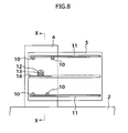
- FIG. 8 is a side view of a principal portion, showing one side of a movable fence
- FIG. 9 is a sectional view taken along the line X-X of FIG. 8.
- reference numeral 1 denotes a platform door, in which two movable fences 5 are supported so as to be slidable in the direction indicated by arrows in FIG. 7 in such a manner as to overlap with each other in the longitudinal direction (the direction perpendicular to a side edge 3 of a platform 2, namely, the direction perpendicular to the car running direction) of a fence member 4 erected at the side edge 3 of the platform 2.
- the movable fence 5 goes in and out through a gateway 7 formed in each side surface portion 6 of the fence member 4.
- the movable fence 5 is rotatably provided with two guide roller members 10 on the upper and lower sides, and two guide rails 11 are fixed to the upper and lower sides of the fence member 4.
- the two movable fences 5 can be moved smoothly in a reciprocating manner with respect to the fence member 4.
- the fence member 4 is provided with drive motors 12, and a pinion 13 is provided on the output shaft of each of the drive motors 12.
- a rack 14 engaging with the pinion 13 is provided in parallel with the guide rails 11. Therefore, when the drive motor 12 is rotated, the movable fence 5 is moved in a reciprocating manner as indicated by an arrow in FIG. 7 by the engagement of the pinion 13 with the rack 14.
- the fence member 4 is provided with a cover 22, one end portion of which is fixed at the upper end of the support plate 21.
- the whole of the support plates 20 and 21 and the movable fences 5 that go into and out of the fence member 4 is covered with the cover 22 so that a relatively moving portion between the support plates 20 and 21 and the movable fences 5 is not exposed to the outside, and dust etc. is prevented from entering into the relatively moving portion from the outside.
- the gateways 7 are open in side surface portions 6 of the cover 22 so that the movable fences 5 go in and out through the gateways 7.
- the platform door device has a construction such that the fence member 4 is erected along the side edge 3 of the platform 2; the movable fences 5 are arranged in parallel with each other in the side portions of the two support plates 20 and 21; the roller members 10, the drive motors 12, and the like are arranged between the support plates 20 and 21 and the movable fences 5; and further the elements within the fence member 4 are covered with the cover 22. Therefore, the thickness of the fence member 4, namely, a width W0 (refer to FIG. 9) in the direction perpendicular to the side edge 3 of the platform 2 increases undesirably.
- the increase in the thickness W0 of the fence member 4 obstructs the space along the side edge 3 of the platform 2, and hence hinders passengers and other people from passing. Also, on a platform 2 with a narrow width, the platform door device having the above-described construction cannot be adopted.
- the present invention has been made to solve the problems with the related art, and accordingly an object thereof is to provide a platform door device in which two movable fences supported by support members provided along a side edge of a platform so as to be movable relative to the support members are provided so that the width thereof in the direction perpendicular to the side edge of platform is narrow, by which the space along the side edge of platform is increased to enable the space for people to pass through to be increased, and also the platform door device can easily be applied to a platform with a narrow width.
- the present invention provides a platform door device in which two movable fences, which are provided along the side edge of a station platform for getting on and off a car and each supported movably by a support member, move relative to each other in the longitudinal direction of the platform to open and close a passage between the platform side and the car side, wherein the platform door device is configured so that the two support members are erected on the platform and are housed in the two movable fences; and each of the support members is arranged in a plane in the thickness direction of each of the movable fences so as to be covered with the movable fence, by which the movable fence can be moved relatively between the inner surface thereof and the outer surface of the support member.
- a guide rail extending in the travel direction of the movable fence is provided on the upper inner surface of each of the two movable fences; a slide block is installed in the upper end portion of each of the two support members; and the guide rail is moved along the slide block, by which the movable fence is moved relative to the support member.
- a driving system for relatively moving the two movable fences is housed in a driving system housing hole formed in the platform, and the output end of the driving system is connected to the lower end portion of the movable fence via a driving force transmitting system.
- the driving force transmitting system is configured so that a rack, which is provided in the lower end portion of each of the two movable fences, and a pinion, which is rotatably supported on a rotating shaft and engages with the rack, are provided; the driving system is disposed under the pinion; and the power of the driving system is transmitted to the pinion and the rack via a sprocket connected to the output end of the driving system and a chain, by which the two movable fences are moved relatively.
- the driving system for relatively moving the two movable fences is arranged in one side position of either of the movable fences, and the output end of the driving system is connected to the lower end portion of the movable fence via the driving force transmitting system.
- the driving force transmitting system is configured so that a rack provided in the lower end portion of each of the two movable fences and a pinion engaging with the rack are provided; the output end of the driving system is directly connected to the rotating shaft rotatably supporting the pinion; and the power of the driving system is transmitted to the pinion and rack via the rotating shaft, by which the two movable fences are moved relatively.
- a guide rail extending in the travel direction of the movable fence is provided on the upper inner surface of each of the two movable fences; a slide block is installed in the upper end portion of each of the two support members; and the slide block is moved along the guide rail, by which the movable fence is moved relative to the support member.
- each of the support members is arranged in a plane in the thickness direction of each of the movable fences so as to be covered with the movable fence, the width in the direction perpendicular to the side edge of the platform can be reduced significantly as compared with the configuration of the related art, in which two support plates and two movable fences are arranged parallel to each other in the direction perpendicular to the side edge of the platform, the two support plates and the two movable fences are covered with a cover, and further the drive motor is disposed between the movable fence and the support member. Therefore, this platform door device can avoid obstruction of the space along the side edge of the platform and hence hindrance to passing of passengers and other people, and also can provide some extra space to the platform.
- the platform door device in accordance with the present invention can easily adopted even on a platform with a narrow width.
- each of the two support members is arranged in a plane in the thickness direction of each of the movable fences so as to be covered with the movable fence, a relatively moving portion between the support member and the movable fence is not exposed to the outside, and a covering function is provided to prevent dust etc. from entering into the relatively moving portion from the outside. Therefore, unlike the related art, a cover for covering the two support members and two movable fences need not be provided separately. Thereby, the number of parts can be reduced, and the construction can be simplified.
- the drive motor need not be arranged between the movable fence and the support member. Therefore, the width in the direction perpendicular to the side edge of the platform can be reduced significantly as compared with the related art, so that the effective utilization of the platform can be improved.
- the configuration is such that the pinion and the rack are driven by the driving force transmitting system in which the driving system is arranged under the pinion which engages with the rack provided in the lower end portion of the movable fence to move in a reciprocating manner the movable fence via the rack, and the driving system, the sprocket, and the chain are arranged in the height direction. Therefore, the attachment width of the driving system and the driving force transmitting system does not increase in the direction perpendicular to the side edge of the platform, and the driving system and the driving force transmitting system can be arranged in the plane in the thickness direction of the movable fence. From this aspect as well, the effective utilization of the platform can be improved.
- the driving system is disposed in one side position of either of the movable fences. Therefore, unlike the related art, the drive motor need not be arranged between the movable fence and the support member, so that the width in the direction perpendicular to the side edge of the platform can be reduced significantly as compared with the related art, by which the effective utilization of the platform is improved. Moreover, since the pinion is attached to the rotating shaft directly connected to the driving system, a special driving force transmitting system including sprockets and a chain is not needed, so that the construction is simple, and the number of parts can be reduced.
- FIG. 1 is a front view, including a partial cross section, of a platform door device in accordance with a first embodiment of the present invention
- FIG. 2 is a plan view of a principal portion of the platform door device
- FIG. 3 is a view taken in the direction of the arrow A of FIG. 1
- FIG. 4 is a sectional view taken along the line B-B of FIG. 1.
- the platform side front side
- the car side rear side
- reference character 30 denotes a platform
- 30a denotes a side edge of the platform 30.
- Two flat plate shaped support members 32f and 32r are erected and fixed by welding etc. on the top surface of a bed plate 31 installed on the platform 30.
- Reference characters 33f and 33r denote movable fences.
- the movable fences 33f and 33r are configured so as to cover the two support members 32f and 32r, respectively, from the outside over the total height to contain the support members 32f and 32r within the movable fences 33f and 33r, respectively, so that each of the support members 32f and 32r is contained in a plane in the thickness direction of each of the movable fences 33f and 33r.
- two (or more) slide blocks 34f, 34r such as linear ways are installed in the longitudinal direction (hereinafter, the car running direction, namely, the direction along the side edge 30a of the platform 30 is called the longitudinal direction).
- Reference characters 35f and 35r denote beams fixed on the upper inner surfaces of the movable fences 33f and 33r, respectively.
- the beam 35f, 35r extends in the travel direction of the movable fence 33f, 33r.
- Reference characters 36f and 36r denote guide rails which are fixed on the lower surfaces of the beams 35f and 35r and extend in the travel directions of the movable fence 33f and 33r, respectively.
- Reference characters 37f and 37r denote guide plates installed on the lower side surfaces of the support members 32f and 32r, respectively.
- the guide plate 37f, 37r guides the lower part of the movable fence 33f, 33r to the support member 32f, 32r.
- the lower end portion of the movable fence 33f, 33r is formed with a rack 38f, 38r, and the rack 38f, 38r engages with a pinion 44f, 44r.
- the lower end portion of one support member 32r is formed with a hole 32a, and an attachment plate 40 is fixed on the bed plate 31 in a form such as to pass through the hole 32a.
- bearings 41f and 42f on the platform side (front side) and bearings 41r and 42r on the car side (rear side) are installed.
- the bearings 41f and 42f rotatably support a rotating shaft 43f, and the bearings 41r and 42r rotatably support a rotating shaft 43r.
- the shaft end portion of the rotating shaft 43f on the platform side (front side) is fitted with the pinion 44f, and an intermediate portion of the rotating shaft 43r on the car side (rear side) is fitted with the pinion 44r.
- the pinion 44f engages with the rack 38f
- the pinion 44r engages with the rack 38r.
- an intermediate portion of the rotating shaft 43f is fitted with a sprocket 45f
- the shaft end portion of the rotating shaft 43r is fitted with a sprocket 45r.
- Reference character 46 denotes a lower attachment plate fixed on the lower surface of the platform 30.
- the upper surface of the lower attachment plate 46 faces to a driving system housing hole 50 formed in the platform 30.
- a drive motor 47f on the platform side (front side) and a drive motor 47r on the car side (rear side) are mounted so as to be contained in the driving system housing hole 50.
- a sprocket 48f is installed, and on the output shaft of the drive motor 47r, a sprocket 48r is installed.
- the drive motor 47f on the platform side and the drive motor 47r on the car side are arranged side by side in the longitudinal direction of the platform 30.
- the sprocket 48f of the drive motor 47f on the platform side is connected to the sprocket 45f on the rotating shaft 43f side via a chain 49f
- the sprocket 48r of the drive motor 47r on the car side is connected to the sprocket 45r on the rotating shaft 43r side via a chain 49r.
- the movable fence 33f on the platform side is moved reciprocatingly in the longitudinal direction of the platform 30 by the driving motor 47f via the sprocket 48f, the chain 49f, the sprocket 45f on the rotating shaft 43f side, the rotating shaft 43f, the pinion 44f, and the rack 38f
- the movable fence 33r on the car side is moved reciprocatingly in the longitudinal direction of the platform 30 by the driving motor 47r via the sprocket 48r, the chain 49r, the sprocket 45r on the rotating shaft 43r side, the rotating shaft 43r, the pinion 44r, and the rack 38r.
- the turning force of the drive motor 47f on the platform side is transmitted to the sprocket 45f on the rotating shaft 43f side via the sprocket 48f and the chain 49f.
- the rotating shaft 43f which is supported on the bearings 41f and 42f, is rotated by the sprocket 45f, and the pinion 44f fixed on the rotating shaft 43f is rotated.
- the rack 38f engaging with the pinion 44f and the movable fence 33f installed to the rack 38f are moved in a reciprocating manner.
- the movable fence 33f is moved in a reciprocating manner smoothly in the horizontal direction by sliding the beam 35f, which is fixed in the upper portion of the movable fence 33f, and the guide rail 36f on the slide block 34f, which is installed in the upper end portion of the support member 32f.
- the turning force of the drive motor 47r on the car side is transmitted to the sprocket 45r on the rotating shaft 43r side via the sprocket 48r and the chain 49r.
- the rotating shaft 43r which is supported on the bearings 41r and 42r, is rotated by the sprocket 45r, and the pinion 44r fixed on the rotating shaft 43r is rotated.
- the rack 38r engaging with the pinion 44r and the movable fence 33r installed to the rack 38r are moved reciprocatingly.
- the movable fence 33r is moved in a reciprocating manner smoothly in the horizontal direction by sliding the beam 35r, which is fixed in the upper portion of the movable fence 33r, and the guide rail 36r on the slide block 34r, which is installed in the upper end portion of the support member 32r.
- the first embodiment is configured so that the two support members 32f and 32r erected on the platform 30 are covered with the movable fences 33f and 33r, respectively, and the support member 32f, 32r is housed in the plane in the thickness direction of the movable fence 33f, 33r. Therefore, the width W1 (refer to FIG.
- the platform door device of the first embodiment can avoid obstruction of the space along the side edge 30a of the platform 30 and hence hindrance to passing of passengers and other people, and also can provide some extra space to the platform 30. Also, as described above, the width W1 in the direction perpendicular to the side edge 30a of the platform 30 can be reduced significantly, so that the platform door device in accordance with this embodiment can easily be adopted even on the platform 30 with a narrow width.
- the two support members 32f and 32r erected on the platform 30 are covered with the movable fences 33f and 33r, respectively, and the support member 32f, 32r is housed in the plane in the thickness direction of the movable fence 33f, 33r, a relatively moving portion between the support member 32f, 32r and the movable fence 33f, 33r is not exposed to the outside, and a covering function is provided to prevent dust etc. from entering into the relatively moving portion from the outside. Therefore, unlike the related art, a cover for covering the two support members and two movable fences need not be provided separately. Thereby, the number of parts can be reduced, and the construction can be simplified. Also, the thickness of platform door can be decreased accordingly.
- the drive motors 47f and 47r for relatively moving the two movable fences 33f and 33r are housed in the driving system housing hole 50 provided in the platform 30, unlike the related art, the drive motor need not be arranged between the movable fence and the support member.
- This configuration can also significantly reduce the width W1 (refer to FIG. 2) in the direction perpendicular to the side edge 30a of the platform 30 as compared with the related art, so that the effective utilization of the platform 30 can further be improved.
- the configuration is such that the pinion 44f, 44r and the rack 38f, 38r are driven by the driving force transmitting system in which the drive motor 47f, 47r is arranged under the pinion 44f, 44r which engages with the rack 38f, 38r provided in the lower end portion of the movable fence 33f, 33r to reciprocatingly move the movable fence 33f, 33r via the rack 38f, 38r, and the drive motor 47f, 47r, the sprocket 48f, 48r, 45f, 45r, and the chain 44f, 44r are arranged in the height direction.
- the attachment width of the drive motor 47f, 47r and the driving force transmitting system does not increase in the direction perpendicular to the side edge 30a of the platform 30, and the drive motor 47f, 47r and the driving force transmitting system can be arranged in the plane in the thickness direction of the movable fence 33f, 33r. From this aspect as well, the effective utilization of the platform 30 can be improved.
- FIG. 5 is a side view of a principal portion of a platform door device in accordance with a second embodiment of the present invention
- FIG. 6 is a plan view of a principal portion of the platform door device in accordance with the second embodiment.
- drive motors 67f and 67r for driving the movable fences 33f and 33r, respectively, are disposed in one side position of either the movable fence 33f or 33r, preferably, on the side edge 30a side of the platform 30.
- the drive motor 67f on the platform side and the drive motor 67r on the car side each having a miter gear 66f, 66r are installed to an attachment plate 60 fixed the bed plate 31.
- the drive motor 67f on the platform side and the drive motor 67r on the car side are each connected to a rotating shaft 63f, 63r via the miter gear 66f, 66r and a coupling 65f, 65r.
- a pinion 64f, 64r is installed in the shaft end portion of the rotating shaft 63f, 63r, and the pinion 64f, 64r engages with the rack 38f, 38r provided in the lower end portion of the movable fence 33f, 33r.
- Reference characters 61f and 62f denote bearings for rotatably supporting the rotating shaft 63f
- reference characters 61r and 62r denote bearings for rotatably supporting the rotating shaft 63r.
- the drive motors 67f and 67r are disposed in one side position of either the movable fence 33f or 33r (preferably, on the side edge 30a side of the platform 30). Therefore, unlike the related art, the drive motor need not be arranged between the movable fence and the support member, so that the width W2 (refer to FIG. 6) in the direction perpendicular to the side edge 30a of the platform 30 can be reduced as compared with the related art, by which the effective utilization of the platform 30 can be improved.
Landscapes
- Engineering & Computer Science (AREA)
- Mechanical Engineering (AREA)
- Transportation (AREA)
- Platform Screen Doors And Railroad Systems (AREA)
- Refuge Islands, Traffic Blockers, Or Guard Fence (AREA)
Abstract
Description
- The present invention relates to a platform door device applied to a station platform etc. More particularly, it relates to a platform door device in which two movable fences, which are provided along the side edge of a station platform for railroad cars and each supported movably by a support member, move relative to each other in the car running direction on the platform to open and close a passage between the platform side and the car side.
- Among station platforms for railroad cars, the number of platforms each equipped with a platform door device provided with a movable fence has increased to prevent accidents such as passengers falling onto the railway tracks, or passengers coming into contact with a car. Such a platform door device is usually constructed so that two movable fences provided along the side edge of the platform are supported movably by support members, and the two movable fences move relative to each other in the car running direction to open and close a passage between the platform side and the car side.
- FIGS. 7 to 9 show a platform door device disclosed in Patent Document 1 (Japanese Patent Provisional Publication No. 2004-131008). FIG. 7 is a general perspective view, FIG. 8 is a side view of a principal portion, showing one side of a movable fence, and FIG. 9 is a sectional view taken along the line X-X of FIG. 8.
- In FIGS. 7 to 9,
reference numeral 1 denotes a platform door, in which twomovable fences 5 are supported so as to be slidable in the direction indicated by arrows in FIG. 7 in such a manner as to overlap with each other in the longitudinal direction (the direction perpendicular to aside edge 3 of aplatform 2, namely, the direction perpendicular to the car running direction) of afence member 4 erected at theside edge 3 of theplatform 2. Themovable fence 5 goes in and out through agateway 7 formed in eachside surface portion 6 of thefence member 4. - As shown in FIG. 8, the
movable fence 5 is rotatably provided with twoguide roller members 10 on the upper and lower sides, and twoguide rails 11 are fixed to the upper and lower sides of thefence member 4. By the rolling motion of theroller members 10 along theguide rails 11, the twomovable fences 5 can be moved smoothly in a reciprocating manner with respect to thefence member 4. - Also, the
fence member 4 is provided withdrive motors 12, and apinion 13 is provided on the output shaft of each of thedrive motors 12. On the other hand, in a central portion in the height direction of themovable fence 5, arack 14 engaging with thepinion 13 is provided in parallel with theguide rails 11. Therefore, when thedrive motor 12 is rotated, themovable fence 5 is moved in a reciprocating manner as indicated by an arrow in FIG. 7 by the engagement of thepinion 13 with therack 14. - Also, as shown in FIG. 9, within the
fence member 4, twosupport plates platform 3 are arranged. On the side surfaces of thesupport plates drive motor 12 is installed. - Further, the
fence member 4 is provided with acover 22, one end portion of which is fixed at the upper end of thesupport plate 21. The whole of thesupport plates movable fences 5 that go into and out of thefence member 4 is covered with thecover 22 so that a relatively moving portion between thesupport plates movable fences 5 is not exposed to the outside, and dust etc. is prevented from entering into the relatively moving portion from the outside. Thegateways 7 are open inside surface portions 6 of thecover 22 so that themovable fences 5 go in and out through thegateways 7. - The above-described conventional platform door device has problems as described below.
- In the above-described related art, the platform door device has a construction such that the
fence member 4 is erected along theside edge 3 of theplatform 2; themovable fences 5 are arranged in parallel with each other in the side portions of the twosupport plates roller members 10, thedrive motors 12, and the like are arranged between thesupport plates movable fences 5; and further the elements within thefence member 4 are covered with thecover 22. Therefore, the thickness of thefence member 4, namely, a width W0 (refer to FIG. 9) in the direction perpendicular to theside edge 3 of theplatform 2 increases undesirably. - Thereupon, in the above-described related art, the increase in the thickness W0 of the
fence member 4 obstructs the space along theside edge 3 of theplatform 2, and hence hinders passengers and other people from passing. Also, on aplatform 2 with a narrow width, the platform door device having the above-described construction cannot be adopted. - The present invention has been made to solve the problems with the related art, and accordingly an object thereof is to provide a platform door device in which two movable fences supported by support members provided along a side edge of a platform so as to be movable relative to the support members are provided so that the width thereof in the direction perpendicular to the side edge of platform is narrow, by which the space along the side edge of platform is increased to enable the space for people to pass through to be increased, and also the platform door device can easily be applied to a platform with a narrow width.
- To achieve the above object, the present invention provides a platform door device in which two movable fences, which are provided along the side edge of a station platform for getting on and off a car and each supported movably by a support member, move relative to each other in the longitudinal direction of the platform to open and close a passage between the platform side and the car side, wherein the platform door device is configured so that the two support members are erected on the platform and are housed in the two movable fences; and each of the support members is arranged in a plane in the thickness direction of each of the movable fences so as to be covered with the movable fence, by which the movable fence can be moved relatively between the inner surface thereof and the outer surface of the support member.
- In the present invention, preferably, a guide rail extending in the travel direction of the movable fence is provided on the upper inner surface of each of the two movable fences; a slide block is installed in the upper end portion of each of the two support members; and the guide rail is moved along the slide block, by which the movable fence is moved relative to the support member.
- Also, in the present invention, a driving system for relatively moving the two movable fences is housed in a driving system housing hole formed in the platform, and the output end of the driving system is connected to the lower end portion of the movable fence via a driving force transmitting system.
- Further, in the present invention, the driving force transmitting system is configured so that a rack, which is provided in the lower end portion of each of the two movable fences, and a pinion, which is rotatably supported on a rotating shaft and engages with the rack, are provided; the driving system is disposed under the pinion; and the power of the driving system is transmitted to the pinion and the rack via a sprocket connected to the output end of the driving system and a chain, by which the two movable fences are moved relatively.
- Also, in the present invention, the driving system for relatively moving the two movable fences is arranged in one side position of either of the movable fences, and the output end of the driving system is connected to the lower end portion of the movable fence via the driving force transmitting system.
- Further, in the present invention, the driving force transmitting system is configured so that a rack provided in the lower end portion of each of the two movable fences and a pinion engaging with the rack are provided; the output end of the driving system is directly connected to the rotating shaft rotatably supporting the pinion; and the power of the driving system is transmitted to the pinion and rack via the rotating shaft, by which the two movable fences are moved relatively.
- Still further, in the present invention, a guide rail extending in the travel direction of the movable fence is provided on the upper inner surface of each of the two movable fences; a slide block is installed in the upper end portion of each of the two support members; and the slide block is moved along the guide rail, by which the movable fence is moved relative to the support member.
- According to the present invention, since each of the support members is arranged in a plane in the thickness direction of each of the movable fences so as to be covered with the movable fence, the width in the direction perpendicular to the side edge of the platform can be reduced significantly as compared with the configuration of the related art, in which two support plates and two movable fences are arranged parallel to each other in the direction perpendicular to the side edge of the platform, the two support plates and the two movable fences are covered with a cover, and further the drive motor is disposed between the movable fence and the support member. Therefore, this platform door device can avoid obstruction of the space along the side edge of the platform and hence hindrance to passing of passengers and other people, and also can provide some extra space to the platform.
- Also, since the width in the direction perpendicular to the side edge of the platform can be reduced significantly as described above, the platform door device in accordance with the present invention can easily adopted even on a platform with a narrow width. Moreover, according to the present invention, since each of the two support members is arranged in a plane in the thickness direction of each of the movable fences so as to be covered with the movable fence, a relatively moving portion between the support member and the movable fence is not exposed to the outside, and a covering function is provided to prevent dust etc. from entering into the relatively moving portion from the outside. Therefore, unlike the related art, a cover for covering the two support members and two movable fences need not be provided separately. Thereby, the number of parts can be reduced, and the construction can be simplified.
- According to the present invention, since the driving system for relatively moving the two movable fences is housed in the driving system housing hole formed in the platform, unlike the related art, the drive motor need not be arranged between the movable fence and the support member. Therefore, the width in the direction perpendicular to the side edge of the platform can be reduced significantly as compared with the related art, so that the effective utilization of the platform can be improved.
- Also, according to the present invention, the configuration is such that the pinion and the rack are driven by the driving force transmitting system in which the driving system is arranged under the pinion which engages with the rack provided in the lower end portion of the movable fence to move in a reciprocating manner the movable fence via the rack, and the driving system, the sprocket, and the chain are arranged in the height direction. Therefore, the attachment width of the driving system and the driving force transmitting system does not increase in the direction perpendicular to the side edge of the platform, and the driving system and the driving force transmitting system can be arranged in the plane in the thickness direction of the movable fence. From this aspect as well, the effective utilization of the platform can be improved.
- Further, according to the present invention, even in a case where it is impossible to form the driving system housing hole in the platform, the driving system is disposed in one side position of either of the movable fences. Therefore, unlike the related art, the drive motor need not be arranged between the movable fence and the support member, so that the width in the direction perpendicular to the side edge of the platform can be reduced significantly as compared with the related art, by which the effective utilization of the platform is improved. Moreover, since the pinion is attached to the rotating shaft directly connected to the driving system, a special driving force transmitting system including sprockets and a chain is not needed, so that the construction is simple, and the number of parts can be reduced.
-
- FIG. 1 is a front view, including a partial cross section, of a platform door device in accordance with a first embodiment of the present invention;
- FIG. 2 is a plan view of a principal portion of a platform door device in accordance with the first embodiment;
- FIG. 3 is a view taken in the direction of the arrow A of FIG. 1;
- FIG. 4 is a sectional view taken along the line B-B of FIG. 1;
- FIG. 5 is a side view of a principal portion of a platform door device in accordance with a second embodiment of the present invention;
- FIG. 6 is a plan view of a principal portion of a platform door device in accordance with the second embodiment;
- FIG. 7 is a general perspective view of a platform door device in accordance with the related art;
- FIG. 8 is a side view of a principal portion showing one side of a movable fence of a platform door device in accordance with the related art; and
- FIG. 9 is a sectional view taken along the line X-X of FIG. 1.
- The present invention will now be described in detail with reference to an embodiment shown in the accompanying drawings.
- FIG. 1 is a front view, including a partial cross section, of a platform door device in accordance with a first embodiment of the present invention, FIG. 2 is a plan view of a principal portion of the platform door device, FIG. 3 is a view taken in the direction of the arrow A of FIG. 1, and FIG. 4 is a sectional view taken along the line B-B of FIG. 1.
- In the description below, the platform side (front side) is represented by the suffix f, and the car side (rear side) is represented by the suffix r.
- In FIGS. 1 to 4,
reference character 30 denotes a platform, and 30a denotes a side edge of theplatform 30. Two flat plate shapedsupport members bed plate 31 installed on theplatform 30. -
Reference characters movable fences support members support members movable fences support members movable fences - On the upper end surface of the
support member slide blocks side edge 30a of theplatform 30 is called the longitudinal direction). -
Reference characters movable fences beam movable fence Reference characters beams movable fence guide rail slide block movable fence support member -
Reference characters support members guide plate movable fence support member - The lower end portion of the
movable fence rack rack pinion support member 32r is formed with ahole 32a, and anattachment plate 40 is fixed on thebed plate 31 in a form such as to pass through thehole 32a. - On the
attachment plate 40,bearings bearings bearings rotating shaft 43f, and thebearings rotating shaft 43r. - The shaft end portion of the
rotating shaft 43f on the platform side (front side) is fitted with thepinion 44f, and an intermediate portion of therotating shaft 43r on the car side (rear side) is fitted with thepinion 44r. As described above, thepinion 44f engages with therack 38f, and thepinion 44r engages with therack 38r. - Also, an intermediate portion of the
rotating shaft 43f is fitted with asprocket 45f, and the shaft end portion of therotating shaft 43r is fitted with asprocket 45r. -
Reference character 46 denotes a lower attachment plate fixed on the lower surface of theplatform 30. The upper surface of thelower attachment plate 46 faces to a drivingsystem housing hole 50 formed in theplatform 30. On the upper surface of thelower attachment plate 46, adrive motor 47f on the platform side (front side) and adrive motor 47r on the car side (rear side) are mounted so as to be contained in the drivingsystem housing hole 50. On the output shaft of thedrive motor 47f, asprocket 48f is installed, and on the output shaft of thedrive motor 47r, asprocket 48r is installed. - As shown in FIG. 1, the
drive motor 47f on the platform side and thedrive motor 47r on the car side are arranged side by side in the longitudinal direction of theplatform 30. Thesprocket 48f of thedrive motor 47f on the platform side is connected to thesprocket 45f on therotating shaft 43f side via achain 49f, and thesprocket 48r of thedrive motor 47r on the car side is connected to thesprocket 45r on therotating shaft 43r side via achain 49r. - By the above-described construction, the
movable fence 33f on the platform side is moved reciprocatingly in the longitudinal direction of theplatform 30 by the drivingmotor 47f via thesprocket 48f, thechain 49f, thesprocket 45f on therotating shaft 43f side, therotating shaft 43f, thepinion 44f, and therack 38f, and themovable fence 33r on the car side is moved reciprocatingly in the longitudinal direction of theplatform 30 by the drivingmotor 47r via thesprocket 48r, thechain 49r, thesprocket 45r on therotating shaft 43r side, therotating shaft 43r, thepinion 44r, and therack 38r. - Next, the operation of the platform door device in accordance with the first embodiment, which is constructed as described above, will be explained.
- The turning force of the
drive motor 47f on the platform side is transmitted to thesprocket 45f on therotating shaft 43f side via thesprocket 48f and thechain 49f. Therotating shaft 43f, which is supported on thebearings sprocket 45f, and thepinion 44f fixed on therotating shaft 43f is rotated. By the rotation of thepinion 44f, therack 38f engaging with thepinion 44f and themovable fence 33f installed to therack 38f are moved in a reciprocating manner. - The
movable fence 33f is moved in a reciprocating manner smoothly in the horizontal direction by sliding thebeam 35f, which is fixed in the upper portion of themovable fence 33f, and theguide rail 36f on theslide block 34f, which is installed in the upper end portion of thesupport member 32f. - On the other hand, the turning force of the
drive motor 47r on the car side is transmitted to thesprocket 45r on therotating shaft 43r side via thesprocket 48r and thechain 49r. Therotating shaft 43r, which is supported on thebearings sprocket 45r, and thepinion 44r fixed on therotating shaft 43r is rotated. By the rotation of thepinion 44r, therack 38r engaging with thepinion 44r and themovable fence 33r installed to therack 38r are moved reciprocatingly. - The
movable fence 33r is moved in a reciprocating manner smoothly in the horizontal direction by sliding thebeam 35r, which is fixed in the upper portion of themovable fence 33r, and theguide rail 36r on theslide block 34r, which is installed in the upper end portion of thesupport member 32r. - Therefore, if the
drive motor 47f on the platform side and thedrive motor 47r on the car side are rotated in the direction opposite to each other, themovable fence 33f on the platform side and themovable fence 33r on the car side are moved in a reciprocating manner in the direction opposite to each other by the above-described operation, by which a passage for passengers to getting on and off the car formed on the platform is opened and closed. - As described above, the first embodiment is configured so that the two
support members platform 30 are covered with themovable fences support member movable fence side edge 30a of theplatform 30 can be reduced significantly as compared with the configuration of the related art, in which two support members (support plates) and two movable fences are arranged parallel to each other in the direction perpendicular to the side edge of the platform, the two support members and the two movable fences are covered with a cover, and further the drive motor is disposed between the movable fence and the support member. - Thereupon, the platform door device of the first embodiment can avoid obstruction of the space along the
side edge 30a of theplatform 30 and hence hindrance to passing of passengers and other people, and also can provide some extra space to theplatform 30. Also, as described above, the width W1 in the direction perpendicular to theside edge 30a of theplatform 30 can be reduced significantly, so that the platform door device in accordance with this embodiment can easily be adopted even on theplatform 30 with a narrow width. - Furthermore, according to the first embodiment, since the two
support members platform 30 are covered with themovable fences support member movable fence support member movable fence - According to the first embodiment, since the
drive motors movable fences system housing hole 50 provided in theplatform 30, unlike the related art, the drive motor need not be arranged between the movable fence and the support member. This configuration can also significantly reduce the width W1 (refer to FIG. 2) in the direction perpendicular to theside edge 30a of theplatform 30 as compared with the related art, so that the effective utilization of theplatform 30 can further be improved. - Also, according to the first embodiment, the configuration is such that the
pinion rack drive motor pinion rack movable fence movable fence rack drive motor sprocket chain drive motor side edge 30a of theplatform 30, and thedrive motor movable fence platform 30 can be improved. - FIG. 5 is a side view of a principal portion of a platform door device in accordance with a second embodiment of the present invention, and FIG. 6 is a plan view of a principal portion of the platform door device in accordance with the second embodiment.
- In the second embodiment, drive
motors movable fences movable fence side edge 30a side of theplatform 30. - Specifically, in FIGS. 5 and 6, the
drive motor 67f on the platform side and thedrive motor 67r on the car side each having amiter gear 66f, 66r are installed to anattachment plate 60 fixed thebed plate 31. - The
drive motor 67f on the platform side and thedrive motor 67r on the car side are each connected to arotating shaft 63f, 63r via themiter gear 66f, 66r and acoupling 65f, 65r. Apinion 64f, 64r is installed in the shaft end portion of therotating shaft 63f, 63r, and thepinion 64f, 64r engages with therack movable fence Reference characters rotating shaft 63f, and reference characters 61r and 62r denote bearings for rotatably supporting the rotating shaft 63r. - Other configurations are the same as those in the first embodiment, and therefore the same reference characters are applied to the same elements as those in the first embodiment.
- According to the second embodiment, even in a case where it is impossible to form the driving
system housing hole 50 in theplatform 30 as in the first embodiment, thedrive motors movable fence side edge 30a side of the platform 30). Therefore, unlike the related art, the drive motor need not be arranged between the movable fence and the support member, so that the width W2 (refer to FIG. 6) in the direction perpendicular to theside edge 30a of theplatform 30 can be reduced as compared with the related art, by which the effective utilization of theplatform 30 can be improved. - Also, since the
pinion 64f, 64r is attached directly to therotating shaft 63f, 63r directly connected to thedrive motor - The above is a description of the embodiments of the present invention. The present invention is not limited to the above-described embodiments, and various changes and modifications can be made based on the technical concept of the present invention.
Claims (6)
- A platform door device in which two movable fences (33f, 33r), which are provided along a side edge (30a) of a station platform (30) for getting on and off a car and each supported movably by a support member (32f, 32r), move relative to each other in a longitudinal direction of the platform to open and close a passage between the platform side and the car side, characterized in that
the platform door device is configured so that the two support members (32f, 32r) are erected on the platform (30) and are housed in the two movable fences (33f, 33r); and each of the support members (32f, 32r) is arranged in a plane in the thickness direction of each of the movable fences so as to be covered with the movable fence (33f, 33r) , by which the movable fence (33f, 33r) can be moved relatively between the inner surface thereof and the outer surface of the support member ( (32f, 32r). - The platform door device according to claim 1,
characterized in that a driving system for relatively moving the two movable fences (33f, 33r) is housed in a driving system housing hole (50) formed in the platform, and an output end of the driving system is connected to a lower end portion of the movable fence via a driving force transmitting system. - The platform door device according to claim 2,
characterized in that the driving force transmitting system is configured so that a rack (38f, 38r), which is provided in the lower end portion of each of the two movable fences (33f, 33r) , and a pinion (44f, 44r), which is rotatably supported on a rotating shaft (43f, 43r) and engages with the rack (38f, 38r), are provided; the driving system is disposed under the pinion (44f, 44r) ; and the power of the driving system is transmitted to the pinion (44f, 44r) and the rack via a sprocket (45f, 45r) connected to the output end of the driving system and a chain (49f, 49r), by which the two movable fences (33f, 33r) are moved relatively. - The platform door device according to claim 2,
characterized in that the driving system for relatively moving the two movable fences (33f, 33r) is arranged in one side position of either of the movable fences (33f, 33r), and the output end of the driving system is connected to the lower end portion of the movable fence via the driving force transmitting system. - The platform door device according to claim 4,
characterized in that the driving force transmitting system is configured so that a rack (38f, 38r) provided in the lower end portion of each of the two movable fences (33f, 33r) and a pinion (44f, 44r) engaging with the rack (38f, 38r) are provided; the output end of the driving system is directly connected to a rotating shaft (43f, 43r) rotatably supporting the pinion (44f, 44r) ; and the power of the driving system is transmitted to the pinion (44f, 44r) and rack via the rotating shaft (43f, 43r), by which the two movable fences (33f, 33r) are moved relatively. - The platform door device according to any one of claims 1 to 5, characterized in that a guide rail (36f, 36r) extending in the travel direction of the movable fence (33f, 33r) is provided on the upper inner surface of each of the two movable fences (33f, 33r); a slide block (34f, 34r) is installed in the upper end portion of each of the two support members (32f, 32r) ; and the guide rail (36f, 36r) is moved along the slide block (34f, 34r), by which the movable fence (33f, 33r) is moved relative to the support member (32f, 32r).
Applications Claiming Priority (1)
| Application Number | Priority Date | Filing Date | Title |
|---|---|---|---|
| JP2004332611A JP4365768B2 (en) | 2004-11-17 | 2004-11-17 | Platform door equipment |
Publications (1)
| Publication Number | Publication Date |
|---|---|
| EP1659043A1 true EP1659043A1 (en) | 2006-05-24 |
Family
ID=35809665
Family Applications (1)
| Application Number | Title | Priority Date | Filing Date |
|---|---|---|---|
| EP05292387A Withdrawn EP1659043A1 (en) | 2004-11-17 | 2005-11-10 | Platform door device |
Country Status (6)
| Country | Link |
|---|---|
| US (1) | US7685772B2 (en) |
| EP (1) | EP1659043A1 (en) |
| JP (1) | JP4365768B2 (en) |
| KR (1) | KR100681552B1 (en) |
| CN (1) | CN1776179B (en) |
| TW (1) | TWI277554B (en) |
Cited By (3)
| Publication number | Priority date | Publication date | Assignee | Title |
|---|---|---|---|---|
| KR100730563B1 (en) | 2004-08-18 | 2007-06-20 | 나부테스코 가부시키가이샤 | Platform door device and installation method thereof |
| WO2011048391A1 (en) * | 2009-10-23 | 2011-04-28 | Knorr-Bremse Rail Systems (Uk) Ltd | Platform screen door system |
| FR3002780A1 (en) * | 2013-03-04 | 2014-09-05 | Faiveley Transp Tours | BEARING BEARING MODULE, ITS ASSEMBLY, COMPRISING THE SAME, AND METHOD FOR PRODUCING A BARRIER. |
Families Citing this family (15)
| Publication number | Priority date | Publication date | Assignee | Title |
|---|---|---|---|---|
| US20130212948A1 (en) * | 2007-04-20 | 2013-08-22 | Opcon International Holdings, L.P. | Operating assembly for use with automatic sliding and folding doors |
| JP5500670B2 (en) * | 2009-04-30 | 2014-05-21 | 日本信号株式会社 | Home door device |
| CN102639807A (en) * | 2009-10-23 | 2012-08-15 | 克诺尔布莱姆斯轨道系统英国有限公司 | Platform screen door system |
| JP5385766B2 (en) * | 2009-12-04 | 2014-01-08 | 三菱重工交通機器エンジニアリング株式会社 | Home door device |
| JP5654254B2 (en) * | 2010-03-30 | 2015-01-14 | ナブテスコ株式会社 | Platform door equipment |
| US8479448B1 (en) * | 2010-10-12 | 2013-07-09 | David Marshall Mercado | Rut-less roller gate system, fully supported and balanced off ground |
| US20120174488A1 (en) * | 2011-01-12 | 2012-07-12 | Chen Chang Technology Co., Ltd. | Linking-Up Ventilation Door/Window Panel Structure |
| JP2012218448A (en) * | 2011-04-04 | 2012-11-12 | Mitsubishi Electric Corp | Door device |
| CN102561877A (en) * | 2011-12-29 | 2012-07-11 | 深圳市方大自动化系统有限公司 | Half-high safety door transmission system |
| CA2916022C (en) * | 2013-06-14 | 2021-01-05 | Christoph LIEBER | Protective wall for protecting persons from travelling rail vehicles |
| US9297201B1 (en) * | 2014-12-16 | 2016-03-29 | Ron Melnick | Privacy barrier for balcony |
| JP5996054B2 (en) * | 2015-07-23 | 2016-09-21 | 三菱電機株式会社 | Home door device |
| CN109209162B (en) * | 2017-06-30 | 2021-07-09 | 比亚迪股份有限公司 | Sliding doors for platform doors and platform doors having the same |
| CN111577058B (en) * | 2020-04-28 | 2024-12-03 | 中国铁道科学研究院集团有限公司电子计算技术研究所 | Safety protection device |
| CN117533357B (en) * | 2023-12-15 | 2024-04-26 | 浙江海芙德建筑产品有限公司 | Subway shielding door expansion joint device and application method thereof |
Citations (5)
| Publication number | Priority date | Publication date | Assignee | Title |
|---|---|---|---|---|
| EP0134824A1 (en) * | 1983-08-12 | 1985-03-27 | Malkmus-Dörnemann, Carola, Dr. | Cantilevered side sliding gate |
| FR2575984A1 (en) * | 1985-01-14 | 1986-07-18 | Lanciaux Marc | Safety handrail for underground railway platforms |
| GB2204082A (en) * | 1987-04-27 | 1988-11-02 | Westinghouse Brake & Signal | Platform door |
| JP2004114824A (en) * | 2002-09-26 | 2004-04-15 | Hitachi Ltd | Thin movable fence for platform |
| JP2004131008A (en) | 2002-10-11 | 2004-04-30 | Kyosan Electric Mfg Co Ltd | Movable platform fence apparatus |
Family Cites Families (7)
| Publication number | Priority date | Publication date | Assignee | Title |
|---|---|---|---|---|
| US2346388A (en) * | 1942-04-08 | 1944-04-11 | Irving G King & Company | Gate drive |
| US4366649A (en) * | 1981-06-02 | 1983-01-04 | Weigant Frederick E | Automatic gate |
| US5136813A (en) * | 1991-09-23 | 1992-08-11 | Fence Hardware Specialties, Inc. Dba Ameristar Fence Products | Cantilever-type sliding gate |
| US5148630A (en) * | 1991-10-24 | 1992-09-22 | Mario Llorens | Security assembly for a sliding glass door |
| JP4169391B2 (en) | 1998-05-22 | 2008-10-22 | ナブテスコ株式会社 | Platform movable fence |
| JP2002308089A (en) | 2001-04-18 | 2002-10-23 | Hitachi Ltd | Movable fence for platform |
| JP2003328656A (en) | 2002-05-10 | 2003-11-19 | Kanji Asano | Sliding door |
-
2004
- 2004-11-17 JP JP2004332611A patent/JP4365768B2/en not_active Expired - Lifetime
-
2005
- 2005-08-08 TW TW094126757A patent/TWI277554B/en not_active IP Right Cessation
- 2005-09-21 US US11/230,519 patent/US7685772B2/en not_active Expired - Fee Related
- 2005-10-08 CN CN200510113431XA patent/CN1776179B/en not_active Expired - Fee Related
- 2005-11-09 KR KR1020050107164A patent/KR100681552B1/en not_active Expired - Fee Related
- 2005-11-10 EP EP05292387A patent/EP1659043A1/en not_active Withdrawn
Patent Citations (5)
| Publication number | Priority date | Publication date | Assignee | Title |
|---|---|---|---|---|
| EP0134824A1 (en) * | 1983-08-12 | 1985-03-27 | Malkmus-Dörnemann, Carola, Dr. | Cantilevered side sliding gate |
| FR2575984A1 (en) * | 1985-01-14 | 1986-07-18 | Lanciaux Marc | Safety handrail for underground railway platforms |
| GB2204082A (en) * | 1987-04-27 | 1988-11-02 | Westinghouse Brake & Signal | Platform door |
| JP2004114824A (en) * | 2002-09-26 | 2004-04-15 | Hitachi Ltd | Thin movable fence for platform |
| JP2004131008A (en) | 2002-10-11 | 2004-04-30 | Kyosan Electric Mfg Co Ltd | Movable platform fence apparatus |
Non-Patent Citations (1)
| Title |
|---|
| PATENT ABSTRACTS OF JAPAN vol. 2003, no. 12 5 December 2003 (2003-12-05) * |
Cited By (4)
| Publication number | Priority date | Publication date | Assignee | Title |
|---|---|---|---|---|
| KR100730563B1 (en) | 2004-08-18 | 2007-06-20 | 나부테스코 가부시키가이샤 | Platform door device and installation method thereof |
| WO2011048391A1 (en) * | 2009-10-23 | 2011-04-28 | Knorr-Bremse Rail Systems (Uk) Ltd | Platform screen door system |
| FR3002780A1 (en) * | 2013-03-04 | 2014-09-05 | Faiveley Transp Tours | BEARING BEARING MODULE, ITS ASSEMBLY, COMPRISING THE SAME, AND METHOD FOR PRODUCING A BARRIER. |
| WO2014135764A1 (en) * | 2013-03-04 | 2014-09-12 | Faiveley Transport Tours | Platform screen door module, installation thereof, assembly comprising same, and method for producing a barrier |
Also Published As
| Publication number | Publication date |
|---|---|
| JP4365768B2 (en) | 2009-11-18 |
| CN1776179B (en) | 2010-05-12 |
| US20060107596A1 (en) | 2006-05-25 |
| TW200619071A (en) | 2006-06-16 |
| TWI277554B (en) | 2007-04-01 |
| CN1776179A (en) | 2006-05-24 |
| HK1088056A1 (en) | 2006-10-27 |
| KR100681552B1 (en) | 2007-02-09 |
| JP2006142887A (en) | 2006-06-08 |
| US7685772B2 (en) | 2010-03-30 |
| KR20060055335A (en) | 2006-05-23 |
Similar Documents
| Publication | Publication Date | Title |
|---|---|---|
| US7685772B2 (en) | Platform door device | |
| EP2399796B1 (en) | Railway platform door device | |
| JP4425705B2 (en) | Movable home fence device | |
| JP4365693B2 (en) | Gap adjustment device between vehicle and home | |
| JP3850549B2 (en) | Platform movable fence | |
| JP2659488B2 (en) | Sliding door device | |
| JP4169391B2 (en) | Platform movable fence | |
| US20090139144A1 (en) | Telescoping gate system and method | |
| JP4368749B2 (en) | Self-propelled movable platform gate | |
| JP2002308089A (en) | Movable fence for platform | |
| HK1088056B (en) | Platform door device | |
| JP2011116280A (en) | Platform door device | |
| WO2011048391A1 (en) | Platform screen door system | |
| US3160198A (en) | Door operating mechanism for railway cars | |
| PL2035642T3 (en) | Device for driving a leaf of a gate | |
| JP2544291Y2 (en) | Articulated sliding door | |
| JP7649444B2 (en) | Two-level vehicle parking facility | |
| CN117418760A (en) | a platform door | |
| CN114987559B (en) | Platform sliding door set | |
| CN219840574U (en) | Translation gate | |
| KR102204544B1 (en) | Track vehicle system with ascending and descending type two-stage sliding door | |
| JP2009051269A (en) | Platform door equipment | |
| KR200153465Y1 (en) | A single body head of door for a railroad car | |
| US20150274489A1 (en) | Pallet Return in Moving Walkways | |
| JPS6129313B2 (en) |
Legal Events
| Date | Code | Title | Description |
|---|---|---|---|
| PUAI | Public reference made under article 153(3) epc to a published international application that has entered the european phase |
Free format text: ORIGINAL CODE: 0009012 |
|
| 17P | Request for examination filed |
Effective date: 20051117 |
|
| AK | Designated contracting states |
Kind code of ref document: A1 Designated state(s): AT BE BG CH CY CZ DE DK EE ES FI FR GB GR HU IE IS IT LI LT LU LV MC NL PL PT RO SE SI SK TR |
|
| AX | Request for extension of the european patent |
Extension state: AL BA HR MK YU |
|
| 17Q | First examination report despatched |
Effective date: 20060807 |
|
| AKX | Designation fees paid |
Designated state(s): FR GB |
|
| REG | Reference to a national code |
Ref country code: DE Ref legal event code: 8566 |
|
| GRAP | Despatch of communication of intention to grant a patent |
Free format text: ORIGINAL CODE: EPIDOSNIGR1 |
|
| STAA | Information on the status of an ep patent application or granted ep patent |
Free format text: STATUS: THE APPLICATION IS DEEMED TO BE WITHDRAWN |
|
| 18D | Application deemed to be withdrawn |
Effective date: 20080115 |