EP1658810A1 - Procédé et dispositif de modulation d'un stimulus en régime stable - Google Patents
Procédé et dispositif de modulation d'un stimulus en régime stable Download PDFInfo
- Publication number
- EP1658810A1 EP1658810A1 EP05257184A EP05257184A EP1658810A1 EP 1658810 A1 EP1658810 A1 EP 1658810A1 EP 05257184 A EP05257184 A EP 05257184A EP 05257184 A EP05257184 A EP 05257184A EP 1658810 A1 EP1658810 A1 EP 1658810A1
- Authority
- EP
- European Patent Office
- Prior art keywords
- stimulus
- signal
- modulation
- sinusoidal signal
- steady state
- Prior art date
- Legal status (The legal status is an assumption and is not a legal conclusion. Google has not performed a legal analysis and makes no representation as to the accuracy of the status listed.)
- Withdrawn
Links
Images


Classifications
-
- A—HUMAN NECESSITIES
- A61—MEDICAL OR VETERINARY SCIENCE; HYGIENE
- A61B—DIAGNOSIS; SURGERY; IDENTIFICATION
- A61B5/00—Measuring for diagnostic purposes; Identification of persons
- A61B5/24—Detecting, measuring or recording bioelectric or biomagnetic signals of the body or parts thereof
- A61B5/316—Modalities, i.e. specific diagnostic methods
- A61B5/369—Electroencephalography [EEG]
- A61B5/377—Electroencephalography [EEG] using evoked responses
- A61B5/38—Acoustic or auditory stimuli
-
- A—HUMAN NECESSITIES
- A61—MEDICAL OR VETERINARY SCIENCE; HYGIENE
- A61B—DIAGNOSIS; SURGERY; IDENTIFICATION
- A61B5/00—Measuring for diagnostic purposes; Identification of persons
- A61B5/12—Audiometering
- A61B5/121—Audiometering evaluating hearing capacity
-
- A—HUMAN NECESSITIES
- A61—MEDICAL OR VETERINARY SCIENCE; HYGIENE
- A61B—DIAGNOSIS; SURGERY; IDENTIFICATION
- A61B5/00—Measuring for diagnostic purposes; Identification of persons
- A61B5/72—Signal processing specially adapted for physiological signals or for diagnostic purposes
- A61B5/7203—Signal processing specially adapted for physiological signals or for diagnostic purposes for noise prevention, reduction or removal
- A61B5/7207—Signal processing specially adapted for physiological signals or for diagnostic purposes for noise prevention, reduction or removal of noise induced by motion artifacts
Definitions
- This invention relates generally to a method and system for modulating a steady state stimulus and more particularly to a method and system for testing sensory responses of a subject using a modulated stimulus, such as a stimulus for Auditory Steady State Response (ASSR), for auditory testing.
- a modulated stimulus such as a stimulus for Auditory Steady State Response (ASSR), for auditory testing.
- ASSR Auditory Steady State Response
- Living animals generate electrical potentials which, when collected, detected and analysed, can be used for a variety of purposes. For example, synchronous neural activity in a live animal or human brain produces electrical potentials that can be detected at the surface of the scalp with conductive electrodes. These detected potentials can then be used in a wide variety of clinical applications, particularly diagnostic applications.
- Stimulation of sensory systems including but not limited to the auditory and visual systems, with amplitude-modulated (AM) and/or frequency-modulated (FM) tones evoke electrical responses from the brain that correspond to the frequency of modulation. These responses, sustained for the duration of stimulation are known as steady-state responses or steady-state evoked potentials (SSEP).
- AM amplitude-modulated
- FM frequency-modulated
- SSEP steady-state evoked potentials
- ASSR Auditory Steady State Responses
- ASSR Auditory Steady State Responses
- An ASSR is an electric sinusoidal signal, which is believed to originate in the brainstem, typically elicited by a modulated sinusoidal stimulus.
- the stimulus may be a carrier tone of audible frequency range, the amplitude or frequency of which is modulated with a low modulation frequency, typically between 40 and 100 Hz.
- the ASSR signal evoked then has exactly the same frequency of such modulation.
- the ASSR also has a very low amplitude, which causes difficulty in reliably extracting the ASSR signal from noise.
- the general principle of ASSR measurement is described as follows.
- a modulated pure tone is presented to the ear.
- the carrier frequencies are usually conventional audiometric tones, from 125 to 8000 Hz.
- the levels of the frequencies are at or higher than 20 dB SPL.
- the modulation frequencies are typically 40 Hz or within the 70 to 100 Hz range (usually 80 Hz if they are in the 70 to 100Hz range), with a 0.95 modulation index.
- a sinusoidal electric signal (the ASSR), which has a frequency equal to the modulation frequency of the stimulus, appears on the surface of the skull.
- the ASSR can be recorded from the surface of the skull with three electrodes, typically on the vertex, on the temporal bone, and on the lobule.
- This electric signal whose magnitude is typically from 40 to 400 nV, is then amplified with a typical gain of approximately 10,000 VN. It is then passed through a band pass filter, with a typical lower frequency cutoff at 10 to 30 Hz and a higher frequency cutoff at 100 to 300 Hz. The filtered signal is then converted into its digital form and processed.
- Figure 1 depicts a pure-tone ASSR carrier modulated by a pure sinusoidal modulation in the case where Amplitude Modulation is used.
- the frequency spectrum of the resulting stimulus waveform contains only the carrier frequency (f c ) and the two side-band frequencies (f c +f m and f c -f m ). Since the modulation frequency f m is typically much smaller than f c , only those sensorineural pathways that are sensitive to frequencies very close to the carrier are stimulated. This frequency specificity in hearing threshold estimates is clinically valuable for optimizing intervention in patients with hearing loss.
- ASSR signals have the advantage that they are frequency-specific, as noted above, ASSR signals are difficult to detect in the presence of electromagnetic interference due to the ASSR signal's low amplitude relative to other electrical signals recorded from the scalp, such as electroencephalography (EEG), electrocardiography (ECG), electrooculography (EOG), and electromyography (EMG).
- EEG electroencephalography
- ECG electrocardiography
- EOG electrooculography
- EMG electromyography
- An alternative method for estimating frequency-specific hearing thresholds is to use a transient stimulus that consists of a short tone burst.
- the auditory brainstem response (ABR) to the tone burst a response recognizable to trained clinicians, can be detected if the transient sound is above the patient's threshold for hearing.
- ABR auditory brainstem response
- the disadvantage of this method is that a rapid stimulus onset is required to evoke a response that is easier to recognize, but a rapid stimulus onset also results in a broad stimulus spectrum that is not limited to the specific frequency of the tone, i.e. the tone-burst test is not as frequency-specific as the steady-state response is.
- Gorga et al. (Gorga M. P. et al. (1992), Journal of the American Academy of Audiology, 3, 159-165, "Auditory brainstem responses elicited by 1000 Hz tone bursts in patients with sensorineural hearing loss", which is hereby incorporated herein by reference) explored the use of a variety of tone-burst stimulus onset and offset waveforms. This included the use of a waveform providing a short tone-burst described as a "Blackman Envelope".
- the cosine-squared AM technique has the property that it adds a single harmonic to the fundamental modulation frequency.
- the resulting waveform has frequency components at fc, fc +/- fm, and fc +/- 2fm, but at no other frequency.
- John et al. reports that the ASSR signal was enhanced significantly using this technique without compromising frequency specificity.
- John et al. theorized that the improvement in ASSR performance was possibly due to: the cosine squared function causing the stimulus to be close to zero between peaks allowing for the neurons involved in the response to complete their refractory period before being re-stimulated; and the maximum slope of the modulation signal being greater for the cosine-squared function than that for pure sinusoidal modulation.
- the present invention overcomes at least some of the disadvantages of previous approaches by providing a method and system for generating a steady-state stimulus, for example an ASSR stimulus, using a partially rectified cosine as a modulation signal, thus reducing computational complexity, and reducing the size and cost of systems for testing ASSR.
- a method of modulating a steady state stimulus including: generating a steady state stimulus signal; and modulating the steady state stimulus signal by at least a portion of a sinusoidal signal where the stimulus is set to zero during another portion of the sinusoidal signal.
- the stimulus provided to a subject is zero for a portion between peaks and it is believed that this allows the neurons involved to complete their refractory period before being re-stimulated.
- the modulation may be amplitude modulation or frequency modulation.
- the portion of the sinusoidal signal may be the positive portion of the sinusoidal signal.
- the sinusoidal signal may be offset by the addition of a constant.
- the sinusoidal signal may be multiplied by a constant greater than 1 to increase to rate of stimulus onset.
- the sinusoidal signal, the offset and the multiplier may be chosen so that the peak, off time and onset rate of the modulation emulate that for cosine squared modulation.
- the sensory stimulus may be passed through a bandpass filter to eliminate or reduce frequency components of the stimulus that are outside the desired range of stimulation.
- a system for modulating a steady state stimulus including: a steady state stimulus signal generator; a sine wave signal generator; a rectifier for causing the sine wave signal to be zero for all values of the waveform below a predetermined threshold; and a multiplier for combining the steady state stimulus signal and sine wave signal.
- the system further includes an offset generator to offset the sine wave signal by the addition of a constant.
- the multiplier mutiplies the sine wave signal by a constant greater than 1 to increase the rate of stimulus onset.
- system further includes a bandpass filter to filter frequency components of the stimulus signal that are outside the desired range of stimulation.
- a system for testing sensory systems of a subject including: a test signal generator for providing at least one test signal; a modulator for modulating at least one of the at least one test signals by a portion of a sinusoidal signal where the stimulus is set to zero during the other portion of the sinusoidal signal; a transducer for transducing the at least one modulated test signal to create a sensory stimulus, and presenting the stimulus to the subject; a detector for detecting potentials from the subject while substantially simultaneously presenting the stimulus to the subject; and a processor for analyzing the potentials to determine whether the potentials are indicative of the presence of at least one steady-state response to the stimulus.
- the portion of the sinusoidal signal is the positive portion of the sinusoidal signal.
- system further includes an offset generator for offsetting the sinusoidal signal by the addition of a constant.
- system further includes a multiplier for multiplying the sinusoidal signal by a constant greater than 1 to increase to rate of stimulus onset.
- system further includes a bandpass filter to act on the sensory stimulus to eliminate or reduce frequency components of the stimulus that are outside the desired range of stimulation.
- modulation described above may be generated by hardware components acting on an analog or digital signal and/or by application of a software program to a digital signal.
- FIG. 3 shows a side view of an examplary stimulus response system 10.
- Stimulus response system 10 includes a reference electrode module 12.
- reference electrode module 12 includes an electrode 12a and an amplifier component 12b that have been adapted to fit together as a module.
- Such a reference electrode module is described in greater detail in US Patent Application No. 10/690,630, filed October 23, 2003, by Sokolov et al., which is hereby incorporated herein by reference.
- Reference electrode module 12 is electrically coupled to two or more signal electrodes 14.
- two signal electrodes 14 also referred to herein as simply “electrodes 14" are illustrated - a first electrode 14a is illustrated in the foreground while a second electrode 14b (shown in dotted line) is in the background. Electrodes 14a, 14b are electrically coupled to reference electrode module 12 by lead wires 20a, 20b, respectively.
- reference electrode module 12 also acts as the reference electrical ground for electrodes 14a and 14b. Electrical potentials detected by electrodes 14 will be passed into amplifier component 12b for signal amplification.
- the use of short lead wires 20 (usually less than 15-20cm in length on an adult human's head and even shorter on an infant's or small animal's head) results in far less noise being inductively or capacitively coupled to the lead wires that carries the signal from electrodes 14 to the amplifier component 12b than conventional electrode-lead and wire-amplifier arrangements.
- lead wires 20 are preferably taut, motion artifacts that induce noise in the lead wires 20 as they move through static (i.e., time invariant) electromagnetic fields are reduced.
- Reference electrode module 12 and electrodes 14 are affixed or mounted to subject 22 through known adhesives or other fixation methods or mechanisms. Additionally, a conductive substance such as electrode gel, for example, may be used to enhance or ensure electrical conduction between the skin of subject 22 and electrodes 12, 14. Reference electrode module 12 is also electrically coupled to signal processing device 18 by way of connector 16. More particularly, amplifier component 12b is adapted to be electrically connected to lead wires 20a, 20b and connector 16. Connector 16 is preferably a shielded wire allowing amplified electrical potential signals to be transmitted from reference electrode module 12 to signal-processing device 18.
- Signal-processing device 18 operates to generate and modulate a steady state stimulus signal and to receive and process signals received from reference electrode module 12 via connector 16.
- Signal-processing device 18 may be, for example, a conventional signal-processing device that has been adapted to also receive amplified electrical potential signals rather than electrical potentials that have yet to be amplified.
- Signal-processing device 18 may include, for example, a visual display for displaying the generated and received signals, a signal recorder component for recording the signal received for later review and analysis, and various signal-processing circuits and software for processing any signals generated and received. Such signal processing may include circuitry and/or software for further reducing any noise contained in the received amplified signals.
- the signal-processing device 18 is also connected, via transducer connector 24, to a transducer 26.
- the transducer 26 is for applying the stimulus to the subject 22.
- the transducer 26 may be, in this embodiment, an external speaker, a headphone, or an ear inserted speaker, as are known in the art.
- stimulus response system 10 is illustrated in a top view of subject 22.
- lead wires 20a and 20b electrically connect electrodes 14a, 14b to reference electrode module 12.
- an operator affixes reference electrode module 12 and electrodes 14 to a subject in the relevant areas of interest in a manner known to those of ordinary skill in the art.
- the operator also electrically connects, by way of a lead wire 20, each electrode 14 to reference electrode module 12.
- electrode 14a is connected to reference electrode module 12 by way of lead wire 20a
- electrode 14b is connected to reference electrode module 12 by way of lead wire 20b.
- Lead wires 20 may be connected to electrodes 12, 14 prior or after fixation to the subject.
- An operator also electrically connects reference electrode module 12 to signal processing device 18 by way of connector 16. The operator then positions the transducer 26 to appropriately deliver the stimulus signal to the subject 22. In this case, by placing an ear insertion speaker.
- the stimulus for testing the sensory response of the subject may be applied to the subject.
- the stimulus may be a carrier tone of audible frequency range ("steady state stimulus signal") that is modulated with a low modulation frequency, typically between 40 and 100 Hz.
- a partially rectified cosine wave is applied as a modulation signal rather than the conventional sine function or an exponential cosine function.
- b is a bias or offset that determines what portion of the modulation signal is nonzero and m/n is a fraction, usually greater than 1, that determines the slope of the onset of modulation.
- a further advantage of the present technique is that it requires no additional computational power compared to the calculation of conventional sinusoidal modulation. It will be understood to one of skill in the art that the present technique may be implemented using analog components for the generation of a modulating cosine function, adding the offset "b", rectifying the signal so that the resulting waveform is zero for all negative values of the waveform and multiplying the carrier and modulated signals. Alternatively, the technique may be implemented using software on a digital microcomputer or microcontroller to calculate the function or lookup the function.
- the exemplary embodiment also provides a waveform that is less frequency specific than the cosine squared waveform.
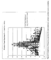
- FIG. 6 shows the power spectrum FFT for partially rectified modulation versus that for cosine squared modulation. From FIG. 6, it is apparent that, for a 1 kHz carrier, the spectrum of the waveform modulated by a partially rectified cosine contains more power in the range of 500-1500 Hz than the spectrum for the waveform modulated by a cosine squared function. The signal power contained outside this range, however, is small compared to the components close to the center frequency and are not likely to affect threshold detection. In one embodiment of this invention, the stimulus may also be band pass filtered to eliminate or reduce these extra frequency components.
- the reference electrode includes an amplifier. It will be understood by one of skill in the art that a more conventional system in which amplification is performed at the signal processing device could also be used.
Applications Claiming Priority (1)
| Application Number | Priority Date | Filing Date | Title |
|---|---|---|---|
| US62942704P | 2004-11-22 | 2004-11-22 |
Publications (1)
| Publication Number | Publication Date |
|---|---|
| EP1658810A1 true EP1658810A1 (fr) | 2006-05-24 |
Family
ID=35811765
Family Applications (1)
| Application Number | Title | Priority Date | Filing Date |
|---|---|---|---|
| EP05257184A Withdrawn EP1658810A1 (fr) | 2004-11-22 | 2005-11-22 | Procédé et dispositif de modulation d'un stimulus en régime stable |
Country Status (2)
| Country | Link |
|---|---|
| US (1) | US20060161075A1 (fr) |
| EP (1) | EP1658810A1 (fr) |
Cited By (2)
| Publication number | Priority date | Publication date | Assignee | Title |
|---|---|---|---|---|
| WO2021155951A1 (fr) * | 2020-02-07 | 2021-08-12 | Universiteit Gent | Procédé et système pour déterminer l'intégrité de fibres et de synapses nerveuses auditives |
| CN113876340A (zh) * | 2014-09-24 | 2022-01-04 | 维沃声波有限公司 | 用于探测诱发响应信号的系统、方法和设备 |
Families Citing this family (8)
| Publication number | Priority date | Publication date | Assignee | Title |
|---|---|---|---|---|
| WO2010141764A2 (fr) * | 2009-06-03 | 2010-12-09 | University Of Pittsburgh - Of The Commonwealth System Of Higher Education | Mesure stable et approche d'analyse pour le profilage de potentiels évoqués auditifs depuis une courte latence jusqu'à une longue latence |
| EP2740279B1 (fr) * | 2011-08-03 | 2021-09-01 | T&W Engineering A/S | Prothèse auditive dotée d'une capacité de réglage automatique |
| WO2019060298A1 (fr) | 2017-09-19 | 2019-03-28 | Neuroenhancement Lab, LLC | Procédé et appareil de neuro-activation |
| US11717686B2 (en) | 2017-12-04 | 2023-08-08 | Neuroenhancement Lab, LLC | Method and apparatus for neuroenhancement to facilitate learning and performance |
| US11478603B2 (en) | 2017-12-31 | 2022-10-25 | Neuroenhancement Lab, LLC | Method and apparatus for neuroenhancement to enhance emotional response |
| US11364361B2 (en) | 2018-04-20 | 2022-06-21 | Neuroenhancement Lab, LLC | System and method for inducing sleep by transplanting mental states |
| WO2020056418A1 (fr) | 2018-09-14 | 2020-03-19 | Neuroenhancement Lab, LLC | Système et procédé d'amélioration du sommeil |
| US11786694B2 (en) | 2019-05-24 | 2023-10-17 | NeuroLight, Inc. | Device, method, and app for facilitating sleep |
Citations (4)
| Publication number | Priority date | Publication date | Assignee | Title |
|---|---|---|---|---|
| US3909705A (en) * | 1972-08-02 | 1975-09-30 | Messrs Spectrospin Ag | Method of and device for recording spin resonance spectra |
| US20010049480A1 (en) * | 2000-05-19 | 2001-12-06 | John Michael Sasha | System and methods for objective evaluation of hearing using auditory steady-state responses |
| US6524258B1 (en) * | 1999-11-13 | 2003-02-25 | Pilot Blankenfelde Medizinisch-Elektronische Geräte GmbH | Method for an objective frequency-specific determination of an audible threshold value using an amplitude modulation following response (AMFR) |
| US20050090727A1 (en) | 2003-10-23 | 2005-04-28 | Vivosonic Inc. | Method and apparatus for the collection of physiological electrical potentials |
-
2005
- 2005-11-22 US US11/283,709 patent/US20060161075A1/en not_active Abandoned
- 2005-11-22 EP EP05257184A patent/EP1658810A1/fr not_active Withdrawn
Patent Citations (4)
| Publication number | Priority date | Publication date | Assignee | Title |
|---|---|---|---|---|
| US3909705A (en) * | 1972-08-02 | 1975-09-30 | Messrs Spectrospin Ag | Method of and device for recording spin resonance spectra |
| US6524258B1 (en) * | 1999-11-13 | 2003-02-25 | Pilot Blankenfelde Medizinisch-Elektronische Geräte GmbH | Method for an objective frequency-specific determination of an audible threshold value using an amplitude modulation following response (AMFR) |
| US20010049480A1 (en) * | 2000-05-19 | 2001-12-06 | John Michael Sasha | System and methods for objective evaluation of hearing using auditory steady-state responses |
| US20050090727A1 (en) | 2003-10-23 | 2005-04-28 | Vivosonic Inc. | Method and apparatus for the collection of physiological electrical potentials |
Non-Patent Citations (5)
| Title |
|---|
| GORGA M. P., JOURNAL OF THE AMERICAN ACADEMY OF AUDIOLOGY, vol. 3, 1992, pages 159 - 165 |
| JOHN M S ET AL: "MULTIPLE AUDITORY STEADY-STATE RESPONSES TO AM AND FM STIMULI", AUDIOLOGY AND NEURO-OTOLOGY, KARGER, BASEL, CH, vol. 6, no. 1, January 2001 (2001-01-01), pages 12 - 27, XP008040668, ISSN: 1420-3030 * |
| JOHN M SASHA ET AL: "Auditory steady-state responses to exponential modulation envelopes.", EAR AND HEARING. APR 2002, vol. 23, no. 2, April 2002 (2002-04-01), pages 106 - 117, XP009062366, ISSN: 0196-0202 * |
| JOHN, M. S., EAR AND HEARING, vol. 23, 2002, pages 106 - 117 |
| PURDY, EAR & HEARING, vol. 23, 2002, pages 358 - 368 |
Cited By (3)
| Publication number | Priority date | Publication date | Assignee | Title |
|---|---|---|---|---|
| CN113876340A (zh) * | 2014-09-24 | 2022-01-04 | 维沃声波有限公司 | 用于探测诱发响应信号的系统、方法和设备 |
| WO2021155951A1 (fr) * | 2020-02-07 | 2021-08-12 | Universiteit Gent | Procédé et système pour déterminer l'intégrité de fibres et de synapses nerveuses auditives |
| WO2021156465A1 (fr) | 2020-02-07 | 2021-08-12 | Universiteit Gent | Procédé et système pour déterminer l'intégrité de fibres et de synapses nerveuses auditives |
Also Published As
| Publication number | Publication date |
|---|---|
| US20060161075A1 (en) | 2006-07-20 |
Similar Documents
| Publication | Publication Date | Title |
|---|---|---|
| EP1658810A1 (fr) | Procédé et dispositif de modulation d'un stimulus en régime stable | |
| JP4707920B2 (ja) | 聴覚上の定常状態応答を使用した聴力を客観的に評価するためのシステム及び方法 | |
| AU2011356277B2 (en) | Personal EEG monitoring device with electrode validation | |
| Van Dun et al. | Estimating hearing thresholds in hearing-impaired adults through objective detection of cortical auditory evoked potentials | |
| Scheer et al. | The influence of amplifier, interface and biological noise on signal quality in high-resolution EEG recordings | |
| Elberling | Action potentials recorded from the promontory and the surface, compared with recordings from the ear canal in man | |
| Wilding et al. | Auditory steady state responses in normal-hearing and hearing-impaired adults: an analysis of between-session amplitude and latency repeatability, test time, and F ratio detection paradigms | |
| Marquardt et al. | Low-frequency characteristics of human and guinea pig cochleae | |
| Aoyagi et al. | An application of phase spectral analysis to amplitude—Modulation following response | |
| Finneran et al. | Place specificity of the click-evoked auditory brainstem response in the bottlenose dolphin (Tursiops truncatus) | |
| Griffiths et al. | The amplitude modulation-following response as an audiometric tool | |
| US20040116825A1 (en) | Method for hearing screening of newborn by means of steady state response evoked with high click rate | |
| Valderrama et al. | Auditory brainstem and middle latency responses recorded at fast rates with randomized stimulation | |
| Hokajärvi | Electrode contact impedance and biopotential signal quality | |
| JP4571709B1 (ja) | 耐振動脳波計 | |
| Thornton | The use of post-auricular muscle responses | |
| Giordano et al. | Multi-source signal processing in phonocardiography: comparison among signal selection and signal enhancement techniques | |
| Bahmer et al. | Recording and online analysis of auditory steady state responses (ASSR) in Matlab | |
| Van Dun et al. | A flexible research platform for multi-channel auditory steady-state response measurements | |
| Hoke et al. | A timesaving BERA technique for frequency-specific assessment of the auditory threshold through tone-pulse series stimulation (TOPSTIM) with simultaneous gliding high-pass noise masking (GHINOMA) | |
| Abdul Jamil et al. | Electrocardiograph (ECG) circuit design and software-based processing using LabVIEW | |
| Ren et al. | Heart beat modulation of spontaneous otoacoustic emissions in guinea pig | |
| Nacéra et al. | Hardware-software preprocessing platform for high immunity ECG recording | |
| Thornton | Distortion of averaged post-auricular muscle responses due to system bandwidth limits | |
| Alwan | Implementation of Wavelet-Kalman Filtering Technique for Auditory Brainstem Response |
Legal Events
| Date | Code | Title | Description |
|---|---|---|---|
| PUAI | Public reference made under article 153(3) epc to a published international application that has entered the european phase |
Free format text: ORIGINAL CODE: 0009012 |
|
| AK | Designated contracting states |
Kind code of ref document: A1 Designated state(s): AT BE BG CH CY CZ DE DK EE ES FI FR GB GR HU IE IS IT LI LT LU LV MC NL PL PT RO SE SI SK TR |
|
| AX | Request for extension of the european patent |
Extension state: AL BA HR MK YU |
|
| AKX | Designation fees paid | ||
| 17P | Request for examination filed |
Effective date: 20061127 |
|
| RBV | Designated contracting states (corrected) |
Designated state(s): DE FR GB |
|
| 17Q | First examination report despatched |
Effective date: 20070213 |
|
| REG | Reference to a national code |
Ref country code: DE Ref legal event code: 8566 |
|
| STAA | Information on the status of an ep patent application or granted ep patent |
Free format text: STATUS: THE APPLICATION IS DEEMED TO BE WITHDRAWN |
|
| 18D | Application deemed to be withdrawn |
Effective date: 20070824 |