EP1658457B1 - Proportionalventilbetätigungsvorrichtung - Google Patents
Proportionalventilbetätigungsvorrichtung Download PDFInfo
- Publication number
- EP1658457B1 EP1658457B1 EP04782503A EP04782503A EP1658457B1 EP 1658457 B1 EP1658457 B1 EP 1658457B1 EP 04782503 A EP04782503 A EP 04782503A EP 04782503 A EP04782503 A EP 04782503A EP 1658457 B1 EP1658457 B1 EP 1658457B1
- Authority
- EP
- European Patent Office
- Prior art keywords
- armature
- valve
- actuating apparatus
- valve actuating
- set forth
- Prior art date
- Legal status (The legal status is an assumption and is not a legal conclusion. Google has not performed a legal analysis and makes no representation as to the accuracy of the status listed.)
- Not-in-force
Links
Images


Classifications
-
- F—MECHANICAL ENGINEERING; LIGHTING; HEATING; WEAPONS; BLASTING
- F16—ENGINEERING ELEMENTS AND UNITS; GENERAL MEASURES FOR PRODUCING AND MAINTAINING EFFECTIVE FUNCTIONING OF MACHINES OR INSTALLATIONS; THERMAL INSULATION IN GENERAL
- F16K—VALVES; TAPS; COCKS; ACTUATING-FLOATS; DEVICES FOR VENTING OR AERATING
- F16K31/00—Actuating devices; Operating means; Releasing devices
- F16K31/02—Actuating devices; Operating means; Releasing devices electric; magnetic
- F16K31/06—Actuating devices; Operating means; Releasing devices electric; magnetic using a magnet, e.g. diaphragm valves, cutting off by means of a liquid
- F16K31/0644—One-way valve
- F16K31/0655—Lift valves
- F16K31/0665—Lift valves with valve member being at least partially ball-shaped
Definitions
- This invention relates to a valve actuating apparatus for controlling fluid flow, and in particular, to a valve actuating apparatus for providing proportional control of the fluid flow from an inlet port to an outlet port in a valve body of the apparatus.
- a plunger of magnetic material is slidable within the solenoid.
- a spring or other biasing means urges the plunger into contact with a valve seat.
- the valve is maintained closed by the spring.
- a magnetic force acts against the spring to move the plunger away from the valve seat.
- the plunger moves out of contact with the valve seat into a remote position in which the valve is fully open.
- a valve of this type has two basic positions, open and closed.
- a proportional valve is one in which the flow of fluid varies in proportion to the current supplied to a coil in the solenoid. Such a valve may be desirable for applications in which a gradual variation in flow is preferable to an abrupt change between on and off conditions.
- proportional valves Many designs have been proposed for proportional valves.
- An example of a known proportional valve is shown in U.S. Patent No. 4,463,332 to W. Everett , .
- the proportional valve in the '332 Patent includes a solenoid having an electromagnetic coil and a pole piece.
- the pole piece is located within the electromagnetic coil, and an armature is located near the pole piece and separated therefrom by a core gap.
- the pole piece is mounted in the solenoid with a threaded engagement which can be adjusted to adjust the core gap.
- the armature is held in place by an armature retainer, and a pair of flat springs are held between the armature retainer and the armature.
- the solenoid in the '332 Patent also includes an annular permanent magnet surrounding the coil to create a field of predetermined flux density in the pole piece.
- the solenoid assembly in the '332 Patent is shown coupled to a valve assembly which utilizes a ball valve.
- the valve actuating apparatus also includes a valve assembly having an armature with first and second shoulders, and first and second springs for biasing the armature one of the springs has a diameter that is greater than the other.
- the valve actuating apparatus also has a solenoid assembly that includes an electromagnetic coil, a core member and a pole piece.
- the core member may have a central bore and first and second shoulders.
- the first spring may be positioned between the first shoulder on the armature and the first shoulder on the core member, and the second spring may be positioned between the second shoulder on the armature and the second shoulder on the core member.
- the pole piece and the armature define a gap that decreases proportionally to the amount of current flowing through the electromagnetic coil.
- Both the springs may be flat springs . Both of the springs may have centrally located holes, and a portion of the armature may be inserted through the holes.
- the hole of the second spring may a diameter that is greater than an outer diameter of the first shoulder of the armature and smaller than an outer diameter of the second shoulder of the armature.
- the valve actuating apparatus further includes a movable fluid control member.
- the springs may bias the armature into contact with the fluid control member.
- the valve actuating apparatus may further include a valve seat, wherein the fluid control member may be in contact with the valve seat to inhibit fluid flow through the apparatus when the electromagnetic coil is not energized.
- the fluid control member may be a ball.
- the inlet port is pressurized and pushes the fluid control member against the armature regardless of the size of the gap.
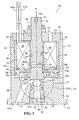
- Figure 1 is a cross-sectional view of a proportional valve actuating apparatus taken through a longitudinal axis of the apparatus and showing the valve in the closed position that prohibits fluid from flowing from an inlet port into an outlet port.
- Figure 1A is a close up view taken as shown in Figure 1 of a fluid control ball biased against a valve seat of the apparatus.
- Figure 2 is a cross-sectional view of the valve actuating apparatus taken in the same plane as Figure 1 showing the valve in an open position allowing fluid to flow from the inlet port to the outlet port when an electromagnetic coil is energized.
- Figure 2A is a close up view taken as shown in Figure 2 , wherein the fluid control ball is separated from the valve seat to permit the fluid flow.
- Figure 3 is a top plan view of a flat spring used in the valve actuating apparatus.
- Figure 4 is a cross-sectional view of an alternate embodiment proportional valve actuating apparatus with the valve in the closed position.
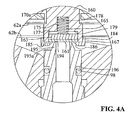
- Figure 4A is a close up view taken as shown in Figure 4 of the seal member seated against the valve seat.
- valve actuating apparatus includes a housing generally indicated as 12, a solenoid assembly generally indicated as 14 and a valve assembly generally indicated as 16.
- Housing 12 includes a valve body 20 and an end piece 22.
- the valve body 20 includes a lower portion 24 having a bottom surface 25 and an upper portion 26 having a bore 28 therein.
- Upper portion 26 also includes an upper end 30, wherein bore 28 is slightly enlarged and has internal threads 31 for receiving the end piece 22.
- Valve body 20 also includes an inlet passage 32 and an outlet passage or port 33. Both inlet passage 32 and outlet passage 33 extend from the bottom surface 25 through lower portion 24 of valve body 20 into bore 28. Inlet passage 32 also includes internal threads 34 extending along a portion thereof. Inlet passage 32 and outlet passage 33 may also each contain a counterbore 35a, 35b, respectively, for receipt of fittings or O-rings to connect fluid conduits (not shown) to carry a fluid (not shown) to and from the valve body.
- End piece 22 has a generally disc-like shape with a centrally located bore 37 having internal threads 38. End piece 22 also has external threads 39 extending about the outer circumference thereof. External threads 39 are threadably engageable with internal threads 31 of the upper end 30 of the valve body.
- the solenoid assembly 14 includes an electromagnetic coil 40, electrical leads 41a, 41b, a pole piece 42, and a core member 44. Electrical leads 41a, 41b provide electrical current to the electromagnetic coil 40 and extend through an opening in the end piece 22.
- the electromagnetic coil 40 is of a standard design and well known in the art.
- Pole piece 42 is manufactured from a ferromagnetic material and includes a lower portion 46 having a bottom surface 46a positioned within the electromagnetic coil 40, and an upper portion 47 extending through bore 37 of end piece 22.
- the upper portion 47 includes external threads 48 that are engageable with threads 38 of the end piece and an adjustment recess 49a for receiving a screwdriver, hex wrench, or other adjustment mechanism (not shown).
- the lower portion 46 of the pole piece includes a groove 49.
- the solenoid assembly 14 also includes an O-ring or other sealing member 50 located in groove 49 of the pole piece to preclude fluid from escaping between the pole piece and the electromagnetic coil. Also, a locking nut 52 is located on external threads 48 of the upper portion 47 of the pole piece and is tightened against the end piece 22.
- Core member 44 of the solenoid assembly has a generally cylindrical configuration and is located in bore 28 of the valve body.
- Core member 44 also has a central bore 53 in which the electromagnetic coil 40 is contained.
- Core member 44 further includes an internal flange 54 and a pair of annular shoulders 55a, 55b extending circumferentially about the lower end of central bore 53. Shoulder 55b is spaced further from a central axis A than shoulder 55a such that the diameter of central bore 53 is greater adjacent shoulder 55b than shoulder 55a.
- Core member 44 also includes an outer circumferential groove 56 for receipt of an O-ring or other sealing member 58 to preclude fluid from escaping between the core member 44 and upper portion 26 of the valve body 20.
- Another O-ring 59 is located between the bottom end of coil 40 and internal flange 54 to preclude fluid from escaping between the coil and the core member.
- the valve assembly 16 of valve actuating apparatus 10 includes an armature 60, a pair of springs 62a, 62b, a fluid control member 64, and a valve insert 66.
- Armature 60 is comprised of a ferromagnetic material and has a generally cylindrical configuration.
- the armature includes a pair of shoulders 70a, 70b that extend about the outer circumference of the armature. It should be noted that the diameter of the armature is wider at shoulder 70b than at shoulder 70a.
- Armature 60 also includes an upper surface 72 and a lower surface 74.
- the upper surface 72 of the armature and the bottom surface 46a of pole piece 42 define a gap 76, as will be described more fully below.
- Spring 62a of valve assembly 16 has a generally flat disc-like configuration ( Figure 3 ) and is preferably made from a non-magnetic corrosion resistant material.
- Spring 62a has an outer circumference 80 that defines its diameter.
- Spring 62a also has a centrally located hole 82 and arcuate slots 84 radiating outwardly in a spiral-like configuration around the central hole to provide the desired mechanical stress to deflection relationship of the springs.
- Spring 62b is similar in configuration to spring 62a except that spring 62b has a larger circumference 80 and diameter, as well as, a larger centrally located hole 82 than spring 62a.
- the springs may be manufactured using known chemical etching techniques. In one embodiment, the springs are relatively high rate springs with a rating of 150 to 500 psi.
- valve insert 66 of valve assembly 16 has a generally cylindrical configuration and includes an inlet port 90 extending therethrough and external threads 92 for engaging internal threads 34 of inlet passage 32.
- Valve insert 66 also includes a valve seat 94 and a circular flange 95 extending upward from the valve seat. Circular flange 95 is configured for receipt of the fluid control member 64, which in the embodiment shown, is a ball ( Figure 1A ).
- Valve insert 66 also includes an outer circumferential groove 96 for receipt of an O-ring or other sealing member 98 to preclude fluid leakage between the valve body 20 and the valve insert 66.
- the solenoid assembly 14 When assembled as shown in the figures, the solenoid assembly 14 is mounted within bore 28 of the valve body 20. Prior to the insertion of the solenoid assembly in the valve body, the armature 60 and springs 62a, 62b are placed within the core member 44. A portion of the armature 60 is inserted through the central holes 82 of springs 62a, 62b, such that spring 62a bears against shoulder 70a of the armature, and spring 62b bears against shoulder 70b of the armature. As such, shoulder 70a of the armature, has an outer diameter that is smaller than and will pass through central hole 82 of spring 62b, but is greater than and will not pass through central hole 82 of spring 62a.
- spring 62a bears against shoulder 55a of core member 44, and the outer portion of spring 62b bears against shoulder 55b of the core member. Also, as can be seen in the figures, the diameter of spring 62a is smaller than that of shoulder 55b so that spring 62a fits past shoulder 55b.
- end piece 22 is screwed into the valve body, such that external threads 39 on the end piece engage internal threads 31 of the upper portion 26 of the valve body.
- External threads 48 on the upper portion 47 of pole piece 42 are threaded with internal threads 38 in the central bore 37 of the end piece to locate the pole piece at the desired position.
- rotation of the pole piece 42 will vary its vertical position, which in turn, will vary the gap 76.
- Lock nut 52 serves to lock the pole piece in place when the desired position is attained. Also, when the apparatus is assembled as shown in the figures, O rings 50, 58, and 59 will inhibit the fluid from escaping through bore 28 out the upper end 30 of the housing.
- valve insert 66 is threaded into inlet passage 32 of valve body 20 by engaging the external threads 92 of the valve insert with internal threads 34 of the inlet passage.
- the fluid control member 64 is placed within the circular flange 95 prior to assembly of the valve insert into the valve body.
- the valve insert is threaded into inlet passage 32 far enough that O rings 98 will seal with lower portion 24 of the valve body and so that the fluid control member is pressed against the lower surface 74 of the armature 60. Accordingly, in this position, spring 62a and spring 62b will bias the armature to push the fluid control member 64 into contact with valve seat 94 ( Figure 1A ).
- the armature will assume a first or closed position as shown in Figure 1 and 1A when the electromagnetic coil 40 is not energized.
- a magnetic field will be established in pole piece 42, which will attract the armature 60 towards it.
- springs 62a, 62b which bear against shoulders 70a, 70b, respectively, of the armature, will provide a resistance against the armature moving toward the pole piece.
- the resistance/tension and resulting flexure in the springs will depend upon the thickness and material used. The tension and flexure in the springs will increase as the current supplied by electrical leads 41a, 41b is increased.
- the springs should be sized such that under the maximum current spring 62a does not come into contact with internal flange 54 of core member 44 and so that upper surface 72 of the armature 60 does not contact the bottom surface 46a of pole piece 42. Note that in the present invention, the armature is fully supported by the springs and does not experience the sliding friction that occurs in many other valves.
- the inlet fluid should be kept under pressure. This will force the fluid control member 64 upward so that it remains in contact with the lower surface 74 of the armature as the armature raises and lowers in response to the magnetic field produced by the current supplied to coil 40.
- the fluid control member moves upward with the armature, it will become displaced from the valve seat 94, and thus allow the fluid to flow from the inlet port 90 to the outlet port 33.
- the more current that is provided to the coil the stronger the magnetic field will be, and the farther the armature will move upward to reduce gap 76. Accordingly, the amount of displacement of the fluid control member 64 from the valve seat 94 will coincide directly with the movement of the armature providing proportional control of the fluid flow.
- the circular flange 95 prevents the fluid control member 64 from being dislocated away from the inlet port 90 as shown in Figure 2A .
- the springs used in the invention have a relatively high rate, and the armature has a relatively small mass, the system tends to be very responsive to changes in the current supplied to coil 40.
- the flat springs are designed to achieve a long life by means of the material selected and controlling the displacement so that the stress is kept to 20% of the maximum yield strength.
- Adjustment to the valve may be made to vary the displacement of the fluid control member versus the electrical signal by loosening the lock nut 52 and rotating the pole piece 42 using a hex wrench or other tool in adjustment recess 49a. This will vary the gap 76 as external threads 48 of pole piece 42 are rotated relative to internal threads 38 of end piece 22. The smaller the gap is, the stronger the magnetic attraction will be between the armature and the pole piece. Once the desired position of the pole piece is attained, the lock nut is retightened against the end piece 22. An adjustment to the valve may also be made by rotating the valve insert 66. The engagement of the threads on the valve insert with the threads on the valve body will cause the valve seat 94 and the fluid control member 64 to be raised or lowered as the valve insert is rotated.
- valve actuating apparatus 110 is similar in all respects to valve actuating apparatus 10 except that it contains a modified valve assembly 116 that does not utilize a ball valve.
- Valve assembly 116 includes springs 62a, 62b, an armature 160, a sealing or fluid control member 161, a backing plate 163, a third spring 165, a valve insert 166, and a cap 167.
- Armature 160 is comprised of a ferromagnetic material and has a generally cylindrical configuration. Armature 160 includes a circumferential shoulder 170a, but in the embodiment shown, the armature does not have a second integral circumferential shoulder as does armature 60. Armature 160 also includes an upper surface 172 and a lower surface 174. Lower surface 174 has a bore 175, with a counterbore 177 of increased diameter at the outer end thereof. Bore 175 includes an end surface 178 and a transition surface 179 extending outward to counterbore 177. Bore 175 is configured to receive third spring 165, and counterbore 177 is configured for receipt of sealing member 161 and backing plate 163.
- sealing member 161 has a generally disk-like shape and is made from an elastomeric material.
- Backing plate 163 is also shaped as a disk, and may have a diameter similar to that of sealing member 161.
- the backing plate may be made from a corrosion resistant material such as stainless steel or plastic to provide support for sealing member 161.
- Cap 167 has a generally annular or ring-like configuration in one embodiment and an L-shaped cross section having a longitudinally extending leg 184 and an inwardly extended leg 185. Inwardly extending leg 185 has a tapered end 186.
- Springs 62a, 62b may be of a similar design to that used in valve assembly 16 of valve actuating apparatus 10.
- the third spring 165 is a relatively soft coil spring in the embodiment shown.
- Valve insert 166 has a generally cylindrical configuration and includes an inlet port 190 and external threads 192 for engaging internal threads 34 of inlet passage 32. Valve insert 166 also includes a valve seat 194 located at the end of a circular extension 195 that has an outer sloped or tapered surface 195a. An outer circumferential groove 196 is located in valve insert 166 for receipt of O-ring or sealing member 98 to preclude fluid leakage between valve body 20 and valve insert 166.
- valve assembly 116 In assembling valve assembly 116, spring 165 is placed in bore 175 against surface 178. Backing plate 163 is then positioned against spring 165, and sealing member 161 is placed upon backing plate 163 as best shown in Figure 4A . Cap 167 is used to secure sealing member 161, backing plate 163 and spring 165 within bore 175/counterbore 177 so that sealing member 161 is biased toward leg 185 of cap 167 by spring 165. Cap 167 may be secured on armature 160 using threads, an adhesive, or a press fit.
- armature 160 As with armature 60, a portion of armature 160 is inserted through central hole 82 of springs 62a, 62b such that spring 62a bears against shoulder 170a of the armature.
- Spring 62b bears against leg 184 of cap 167, which serves as the second shoulder in this embodiment.
- the outer portion of springs 62a, 62b bear against respective shoulders 55a, 55b of core member 44, the same as in valve assembly 16. The assembly is retained within housing 12 by end piece 22 as described above in the previous embodiment.
- Valve insert 166 is threaded into inlet passage 32 of valve body 20 by engaging external threads 192 of the valve insert with internal threads 34 of the inlet passage. Valve insert 166 is threaded far enough into inlet passage 32 so that valve seat 194 bears against and forms a sealing engagement with sealing member 161 while coil 40 is in a non-energized state.
- sealing member 161 and backing plate 163 are resiliently supported by spring 165 so that any dimensional instability of the elastomer associated with solvent swell or thermal expansion is absorbed by the spring and does not affect the initial gap 76 between armature 160 and pole piece 42.
- armature 160 is attracted to pole piece 42, which pulls sealing member 161 away from valve seat 194.
- valve assembly 116 provides proportional control of the fluid flow based upon the current. Accordingly, the greater the current provided to the electromagnetic coil, the larger the magnetic field is in pole piece 42 such that the distance between sealing member 161 and valve seat 194 varies directly with the current.
- the valve may be adjusted by rotating pole piece 42 or the valve insert as discussed above.
- valve assembly does not rely on the pressure of the fluid to maintain a ball against the armature. Rather, this means that the valve will operate under any fluid pressure, and the fluid flow may also be operated in a reverse direction so that passage 33 is the fluid inlet and passage 32 is the fluid outlet.
Landscapes
- Engineering & Computer Science (AREA)
- General Engineering & Computer Science (AREA)
- Mechanical Engineering (AREA)
- Magnetically Actuated Valves (AREA)
- Fluid-Driven Valves (AREA)
- Catching Or Destruction (AREA)
Claims (14)
- Ventilbetätigungsvorrichtung (10 oder 110) zum Schaffen einer proportionalen Steuerung einer Fluidströmung, aufweisend:ein Gehäuse (12), das einen Ventilkörper (20) mit einer Einlassöffnung (32) und einer Auslassöffnung (33) aufweist;eine Ventilanordnung (16 oder 116), die einen Anker (60 oder 160) mit einer ersten (70a oder 170a) und einer zweiten Schulter (70b oder 184) sowie mit einer ersten (62a) und einer zweiten Feder (62b) zum Vorspannen des Ankers (60 oder 160) aufweist, wobei eine der Federn einen größeren Durchmesser als die andere aufweist; undeine Solenoidanordnung (14), die eine elektromagnetische Spule (40), ein Kernelement (44) und ein Polstück (42) beinhaltet, wobei das Kernelement (44) eine zentrale Öffnung (53) sowie eine erste (55a) und eine zweite Schulter (55b) aufweist, wobei die erste Feder (62a) zwischen der ersten Schulter (70a oder 170a) an dem Anker (60 oder 160) und der ersten Schulter (55a) an dem Kernelement (44) angeordnet ist und die zweite Feder (62b) zwischen der zweiten Schulter (70b oder 184) an dem Anker (60 oder 160) und der zweiten Schulter (55b) an dem Kernelement (44) angeordnet ist, wobei das Polstück (42) und der Anker (60 oder 160) einen Spalt (76) bilden, der proportional zu der durch die elektromagnetische Spule (40) fließenden Strommenge geringer wird.
- Ventilbetätigungsvorrichtung (10 oder 110) nach Anspruch 1,
wobei es sich bei beiden Federn (62a, 62b) um Flachfedern handelt. - Ventilbetätigungsvorrichtung (10 oder 110) nach Anspruch 1 oder 2,
wobei beide Federn (62a, 62b) zentral angeordnete Öffnungen (82) aufweisen und ein Bereich des Ankers (60 oder 160) durch die Öffnungen (82) hindurchgeführt ist. - Ventilbetätigungsvorrichtung (10 oder 110) nach Anspruch 3,
wobei ein Durchmesser der Öffnung (82) der zweiten Feder (62b) größer ist als ein Außendurchmesser der ersten Schulter (70a oder 170a) des Ankers (60 oder 160) und kleiner ist als ein Durchmesser der zweiten Schulter (70b oder 184) des Ankers (60 oder 160). - Ventilbetätigungsvorrichtung (10 oder 110) nach einem der Ansprüche 1 bis 4,
weiterhin aufweisend ein bewegliches Fluidsteuerelement (64 oder 161). - Ventilbetätigungsvorrichtung (10) nach Anspruch 5,
wobei die Federn (62a, 62b) den Anker (60) in Berührung mit dem Fluidsteuerelement (64) vorspannen. - Ventilbetätigungsvorrichtung (10 oder 110) nach einem der Ansprüche 1 bis 6,
weiterhin aufweisend einen Ventilsitz (94 oder 194), und wobei das Fluidsteuerelement (64 oder 161) mit dem Ventilsitz (94 oder 194) in Kontakt steht, um eine Fluidströmung durch die Vorrichtung (10 oder 110) zu unterbinden, wenn die elektromagnetische Spule (40) nicht aktiviert ist. - Ventilbetätigungsvorrichtung (10) nach einem der Ansprüche 5 bis 7,
wobei es sich bei dem Fluidsteuerelement (64) um eine Kugel handelt. - Ventilbetätigungsvorrichtung (10 oder 110) nach einem der Ansprüche 5 bis 8,
wobei das in die Einlassöffnung (32) eintretende Fluid mit Druck beaufschlagt wird und das Fluidsteuerelement (64 oder 161) in Richtung auf den Anker (60 oder 160) drückt. - Ventilbetätigungsvorrichtung (110) nach einem der Ansprüche 1 bis 5 oder 7,
wobei mindestens eine der Schultern (184) an dem Anker (160) durch einen an dem Anker (160) angebrachten Ring (167) gebildet ist. - Ventilbetätigungsvorrichtung (110) nach einem der Ansprüche 1 bis 5, 7 oder 10,
weiterhin aufweisend ein Dichtungselement (161) und eine dritte Feder (165). - Ventilbetätigungsvorrichtung (110) nach Anspruch 11,
wobei es sich bei dem Ring (167) um eine Abdeckung handelt und die dritte Feder (165) das Dichtungselement (161) in Richtung auf die Abdeckung (167) vorspannt. - Ventilbetätigungsvorrichtung (110) nach einem der Ansprüche 1 bis 12
wobei eine Fluidströmung von der Einlassöffnung (32) zu der Auslassöffnung (33) mit kleiner werdendem Spalt (76) proportional größer wird. - Ventilbetätigungsvorrichtung (10) nach einem der Ansprüche 1 bis 13,
wobei die Feder(62a) eine im Wesentlichen kreisförmige Konfiguration aufweist.
Applications Claiming Priority (2)
| Application Number | Priority Date | Filing Date | Title |
|---|---|---|---|
| US10/649,253 US6974117B2 (en) | 2003-08-27 | 2003-08-27 | Proportional valve actuating apparatus |
| PCT/US2004/028036 WO2005022017A1 (en) | 2003-08-27 | 2004-08-27 | Proportional valve actuating apparatus |
Publications (2)
| Publication Number | Publication Date |
|---|---|
| EP1658457A1 EP1658457A1 (de) | 2006-05-24 |
| EP1658457B1 true EP1658457B1 (de) | 2010-01-20 |
Family
ID=34216901
Family Applications (1)
| Application Number | Title | Priority Date | Filing Date |
|---|---|---|---|
| EP04782503A Not-in-force EP1658457B1 (de) | 2003-08-27 | 2004-08-27 | Proportionalventilbetätigungsvorrichtung |
Country Status (6)
| Country | Link |
|---|---|
| US (1) | US6974117B2 (de) |
| EP (1) | EP1658457B1 (de) |
| AT (1) | ATE455990T1 (de) |
| DE (1) | DE602004025255D1 (de) |
| DK (1) | DK1658457T3 (de) |
| WO (1) | WO2005022017A1 (de) |
Families Citing this family (21)
| Publication number | Priority date | Publication date | Assignee | Title |
|---|---|---|---|---|
| US6974117B2 (en) | 2003-08-27 | 2005-12-13 | South Bend Controls, Inc. | Proportional valve actuating apparatus |
| DE102006003491B4 (de) * | 2006-01-25 | 2014-08-28 | Robert Bosch Gmbh | Magnetventil |
| EP1914458A1 (de) * | 2006-10-18 | 2008-04-23 | Varian B.V. | Ventil mit Schwingungsdämpfung |
| US8167000B2 (en) * | 2007-04-05 | 2012-05-01 | Mac Valves, Inc. | Balanced solenoid valve |
| US8151824B2 (en) * | 2007-04-05 | 2012-04-10 | Mac Valves, Inc. | Balanced solenoid valve |
| US7777603B2 (en) * | 2007-05-03 | 2010-08-17 | Eaton Corporation | Armature and solenoid assembly |
| US8104511B2 (en) * | 2007-08-27 | 2012-01-31 | Parker Hannifin Corporation | Sequential stepped directional control valve |
| US20090283166A1 (en) * | 2008-05-19 | 2009-11-19 | Dnj Components, Llc | Transmission solenoid adapter |
| US8430378B2 (en) * | 2008-05-30 | 2013-04-30 | South Bend Controls Holdings Llc | High flow proportional valve |
| US20100314568A1 (en) * | 2009-06-15 | 2010-12-16 | South Bend Controls, Inc. | Solenoid coil |
| ATE505680T1 (de) * | 2009-06-24 | 2011-04-15 | Hawe Hydraulik Se | Einschraub-wege-sitzventil |
| DE202012009368U1 (de) | 2012-09-28 | 2012-11-09 | Bürkert Werke GmbH | Dichtungssystem für ein Magnetventil sowie Magnetventil |
| EP2954242B1 (de) * | 2013-02-08 | 2017-11-22 | Norgren GmbH | Proportionalventil |
| DE102013016548B3 (de) * | 2013-10-04 | 2015-02-12 | Festo Ag & Co. Kg | Beweglicher Anker eines Magnetventils und damit ausgestattetes Magnetventil |
| JP2015152156A (ja) * | 2014-02-19 | 2015-08-24 | 株式会社テージーケー | 電磁弁 |
| US9574676B2 (en) | 2015-01-23 | 2017-02-21 | Honeywell International Inc. | High-temperature and high-vibration capable armature assemblies for torque motor valve actuators |
| EP3259510B1 (de) | 2015-02-17 | 2020-01-15 | Enfield Technologies, Inc. | Solenoidvorrichtung |
| JP6561615B2 (ja) * | 2015-06-18 | 2019-08-21 | 株式会社デンソー | 弁装置 |
| US10330065B2 (en) * | 2016-03-07 | 2019-06-25 | Stanadyne Llc | Direct magnetically controlled inlet valve for fuel pump |
| US10082217B2 (en) | 2016-12-08 | 2018-09-25 | Honeywell International Inc. | High-temperature and high-vibration capable armature assemblies for torque motor valve actuators with increased winding volume |
| US20200118736A1 (en) * | 2018-10-12 | 2020-04-16 | Borgwarner Inc. | Bobbin posts to assemble a solenoid |
Family Cites Families (27)
| Publication number | Priority date | Publication date | Assignee | Title |
|---|---|---|---|---|
| US3423062A (en) | 1967-09-27 | 1969-01-21 | Itt | Solenoid pilot operated valve |
| US3796229A (en) | 1972-11-20 | 1974-03-12 | Robertshaw Controls Co | Dual valve actuator assembly |
| US3960361A (en) | 1975-03-14 | 1976-06-01 | Bertea Corporation | Solenoid valve |
| US4349045A (en) | 1978-12-26 | 1982-09-14 | Kah Jr Carl L C | Magnetically actuated pilot valve |
| US4527590A (en) | 1982-08-30 | 1985-07-09 | Eaton Corporation | A.C. solenoid three way pilot valve |
| US4463332A (en) | 1983-02-23 | 1984-07-31 | South Bend Controls, Inc. | Adjustable, rectilinear motion proportional solenoid |
| FR2609518B1 (fr) | 1987-01-12 | 1990-12-28 | Abx Sa | Microelectrovanne de commutation a une seule membrane |
| US4767097A (en) | 1987-03-27 | 1988-08-30 | William F. Everett | Stacked servoid assembly |
| US4834337A (en) * | 1988-04-04 | 1989-05-30 | William J. Chorkey | Solenoid operated valve with solenoid wattage adjustment means |
| IE61313B1 (en) | 1988-06-30 | 1994-10-19 | Abx Sa | Switching microelectrovalve having a single diaphragm |
| US4954799A (en) | 1989-06-02 | 1990-09-04 | Puritan-Bennett Corporation | Proportional electropneumatic solenoid-controlled valve |
| FR2671597B1 (fr) | 1991-01-16 | 1993-07-09 | Eaton Sa Monaco | Electrovanne a section de passage variable. |
| US5199462A (en) | 1992-03-18 | 1993-04-06 | Automatic Switch Company | Valve having rocker valve member and isolation diaphragm |
| US5232196A (en) | 1992-03-31 | 1993-08-03 | Ldi Pneutronics Corporation | Proportional solenoid controlled valve |
| JPH0763273A (ja) | 1993-08-26 | 1995-03-07 | Matsushita Refrig Co Ltd | 電磁弁 |
| DE4405657A1 (de) | 1994-02-22 | 1995-08-24 | Buerkert Werke Gmbh & Co | Magnetventil |
| DE4425540C2 (de) | 1994-07-19 | 2003-05-22 | Buerkert Werke Gmbh & Co | Modulares Ventil für strömende Medien |
| US5799696A (en) | 1995-10-18 | 1998-09-01 | Parker-Hannifin Corporation | Solenoid actuated toggle valve |
| US5785298A (en) * | 1996-04-15 | 1998-07-28 | Teknocraft, Inc. | Proportional solenoid-controlled fluid valve assembly |
| US5785297A (en) * | 1996-07-16 | 1998-07-28 | Millipore Corporation | Valve mechanism |
| DE19718408A1 (de) | 1997-04-30 | 1998-11-05 | Nass Magnet Gmbh | Mehrwegeventil |
| US6003552A (en) | 1998-07-13 | 1999-12-21 | Automatic Switch Company | Rocker valve for sealing large orifices |
| DE19854620C2 (de) | 1998-11-26 | 2001-05-17 | Festo Ag & Co | Ventileinrichtung, insbesondere Verstärker |
| DE29901855U1 (de) | 1999-02-03 | 1999-04-08 | Buerkert Werke Gmbh & Co | Fluidisches Steuerelement |
| US6325354B1 (en) | 1999-04-07 | 2001-12-04 | Hewlett-Packard Company | Magnetically-actuated fluid control valve |
| US6460558B2 (en) | 2000-12-04 | 2002-10-08 | Sauer-Danfoss, Inc. | Pilot stage or pressure control pilot valve having a single armature/flapper |
| US6974117B2 (en) | 2003-08-27 | 2005-12-13 | South Bend Controls, Inc. | Proportional valve actuating apparatus |
-
2003
- 2003-08-27 US US10/649,253 patent/US6974117B2/en not_active Expired - Fee Related
-
2004
- 2004-08-27 AT AT04782503T patent/ATE455990T1/de not_active IP Right Cessation
- 2004-08-27 DE DE602004025255T patent/DE602004025255D1/de active Active
- 2004-08-27 EP EP04782503A patent/EP1658457B1/de not_active Not-in-force
- 2004-08-27 WO PCT/US2004/028036 patent/WO2005022017A1/en active Application Filing
- 2004-08-27 DK DK04782503.9T patent/DK1658457T3/da active
Also Published As
| Publication number | Publication date |
|---|---|
| ATE455990T1 (de) | 2010-02-15 |
| DK1658457T3 (da) | 2010-03-08 |
| US6974117B2 (en) | 2005-12-13 |
| US20050045840A1 (en) | 2005-03-03 |
| EP1658457A1 (de) | 2006-05-24 |
| WO2005022017A1 (en) | 2005-03-10 |
| DE602004025255D1 (de) | 2010-03-11 |
Similar Documents
| Publication | Publication Date | Title |
|---|---|---|
| EP1658457B1 (de) | Proportionalventilbetätigungsvorrichtung | |
| US8430378B2 (en) | High flow proportional valve | |
| CA2194116C (en) | Proportional variable force solenoid control valve | |
| US6843465B1 (en) | Memory wire actuated control valve | |
| CA2020787C (en) | Proportional electropneumatic solenoid-controlled valve | |
| US5110087A (en) | Variable force solenoid hydraulic control valve | |
| US4790345A (en) | Proportional valve | |
| EP2614278B1 (de) | Ventil mit druckausgleich und einem membranen-enddichtungselement | |
| EP0683445A1 (de) | Elektromagnetisches Ventil mit einstellbarer Motorkraft | |
| US5207245A (en) | Solenoid valve and valve calibrating method | |
| US5217200A (en) | Solenoid valve | |
| CA3011059C (en) | Diaphragm valve | |
| US6935612B2 (en) | Solenoid valve | |
| US6367766B1 (en) | Proportional flow valve | |
| US20050145812A1 (en) | Solenoid valve and poppet assembly | |
| WO2006065786A2 (en) | Magnetically-actuated manually-operated isolation valve | |
| CA3143183A1 (en) | Proportional solenoid valve | |
| US7246787B2 (en) | Solenoid valve assembly | |
| EP0844624B1 (de) | Elektrisch betätigtes Drucksteuerventil | |
| US10948102B2 (en) | Two-stage fluid control valve having a first stage bi-stable two-port valve and a second stage microvalve | |
| US20240093790A1 (en) | Pilot valve having diaphragm | |
| US11698143B2 (en) | Solenoid valve with permanent magnets | |
| CA1137534A (en) | Solenoid with unrestrained disk-type armature | |
| CN115492934A (zh) | 阀组件 | |
| NZ741227A (en) | Diaphragm Valve |
Legal Events
| Date | Code | Title | Description |
|---|---|---|---|
| PUAI | Public reference made under article 153(3) epc to a published international application that has entered the european phase |
Free format text: ORIGINAL CODE: 0009012 |
|
| 17P | Request for examination filed |
Effective date: 20060221 |
|
| AK | Designated contracting states |
Kind code of ref document: A1 Designated state(s): AT BE BG CH CY CZ DE DK EE ES FI FR GB GR HU IE IT LI LU MC NL PL PT RO SE SI SK TR |
|
| DAX | Request for extension of the european patent (deleted) | ||
| RIN1 | Information on inventor provided before grant (corrected) |
Inventor name: DZIALAKIEWICZ, PAUL Inventor name: NASH, WILLIAM, H. Inventor name: HUTCHINGS, PETER, G. |
|
| 17Q | First examination report despatched |
Effective date: 20080227 |
|
| GRAP | Despatch of communication of intention to grant a patent |
Free format text: ORIGINAL CODE: EPIDOSNIGR1 |
|
| GRAS | Grant fee paid |
Free format text: ORIGINAL CODE: EPIDOSNIGR3 |
|
| GRAA | (expected) grant |
Free format text: ORIGINAL CODE: 0009210 |
|
| AK | Designated contracting states |
Kind code of ref document: B1 Designated state(s): AT BE BG CH CY CZ DE DK EE ES FI FR GB GR HU IE IT LI LU MC NL PL PT RO SE SI SK TR |
|
| REG | Reference to a national code |
Ref country code: GB Ref legal event code: FG4D |
|
| REG | Reference to a national code |
Ref country code: CH Ref legal event code: NV Representative=s name: BUECHEL, VON REVY & PARTNER Ref country code: CH Ref legal event code: EP |
|
| REG | Reference to a national code |
Ref country code: IE Ref legal event code: FG4D |
|
| REG | Reference to a national code |
Ref country code: DK Ref legal event code: T3 |
|
| REF | Corresponds to: |
Ref document number: 602004025255 Country of ref document: DE Date of ref document: 20100311 Kind code of ref document: P |
|
| REG | Reference to a national code |
Ref country code: SE Ref legal event code: TRGR |
|
| REG | Reference to a national code |
Ref country code: NL Ref legal event code: VDEP Effective date: 20100120 |
|
| PG25 | Lapsed in a contracting state [announced via postgrant information from national office to epo] |
Ref country code: AT Free format text: LAPSE BECAUSE OF FAILURE TO SUBMIT A TRANSLATION OF THE DESCRIPTION OR TO PAY THE FEE WITHIN THE PRESCRIBED TIME-LIMIT Effective date: 20100120 |
|
| PG25 | Lapsed in a contracting state [announced via postgrant information from national office to epo] |
Ref country code: PT Free format text: LAPSE BECAUSE OF FAILURE TO SUBMIT A TRANSLATION OF THE DESCRIPTION OR TO PAY THE FEE WITHIN THE PRESCRIBED TIME-LIMIT Effective date: 20100520 Ref country code: NL Free format text: LAPSE BECAUSE OF FAILURE TO SUBMIT A TRANSLATION OF THE DESCRIPTION OR TO PAY THE FEE WITHIN THE PRESCRIBED TIME-LIMIT Effective date: 20100120 Ref country code: ES Free format text: LAPSE BECAUSE OF FAILURE TO SUBMIT A TRANSLATION OF THE DESCRIPTION OR TO PAY THE FEE WITHIN THE PRESCRIBED TIME-LIMIT Effective date: 20100501 |
|
| PG25 | Lapsed in a contracting state [announced via postgrant information from national office to epo] |
Ref country code: FI Free format text: LAPSE BECAUSE OF FAILURE TO SUBMIT A TRANSLATION OF THE DESCRIPTION OR TO PAY THE FEE WITHIN THE PRESCRIBED TIME-LIMIT Effective date: 20100120 Ref country code: SI Free format text: LAPSE BECAUSE OF FAILURE TO SUBMIT A TRANSLATION OF THE DESCRIPTION OR TO PAY THE FEE WITHIN THE PRESCRIBED TIME-LIMIT Effective date: 20100120 Ref country code: PL Free format text: LAPSE BECAUSE OF FAILURE TO SUBMIT A TRANSLATION OF THE DESCRIPTION OR TO PAY THE FEE WITHIN THE PRESCRIBED TIME-LIMIT Effective date: 20100120 |
|
| PG25 | Lapsed in a contracting state [announced via postgrant information from national office to epo] |
Ref country code: GR Free format text: LAPSE BECAUSE OF FAILURE TO SUBMIT A TRANSLATION OF THE DESCRIPTION OR TO PAY THE FEE WITHIN THE PRESCRIBED TIME-LIMIT Effective date: 20100421 Ref country code: RO Free format text: LAPSE BECAUSE OF FAILURE TO SUBMIT A TRANSLATION OF THE DESCRIPTION OR TO PAY THE FEE WITHIN THE PRESCRIBED TIME-LIMIT Effective date: 20100120 Ref country code: EE Free format text: LAPSE BECAUSE OF FAILURE TO SUBMIT A TRANSLATION OF THE DESCRIPTION OR TO PAY THE FEE WITHIN THE PRESCRIBED TIME-LIMIT Effective date: 20100120 Ref country code: CY Free format text: LAPSE BECAUSE OF FAILURE TO SUBMIT A TRANSLATION OF THE DESCRIPTION OR TO PAY THE FEE WITHIN THE PRESCRIBED TIME-LIMIT Effective date: 20100120 Ref country code: BE Free format text: LAPSE BECAUSE OF FAILURE TO SUBMIT A TRANSLATION OF THE DESCRIPTION OR TO PAY THE FEE WITHIN THE PRESCRIBED TIME-LIMIT Effective date: 20100120 |
|
| PLBE | No opposition filed within time limit |
Free format text: ORIGINAL CODE: 0009261 |
|
| STAA | Information on the status of an ep patent application or granted ep patent |
Free format text: STATUS: NO OPPOSITION FILED WITHIN TIME LIMIT |
|
| PG25 | Lapsed in a contracting state [announced via postgrant information from national office to epo] |
Ref country code: SK Free format text: LAPSE BECAUSE OF FAILURE TO SUBMIT A TRANSLATION OF THE DESCRIPTION OR TO PAY THE FEE WITHIN THE PRESCRIBED TIME-LIMIT Effective date: 20100120 Ref country code: BG Free format text: LAPSE BECAUSE OF FAILURE TO SUBMIT A TRANSLATION OF THE DESCRIPTION OR TO PAY THE FEE WITHIN THE PRESCRIBED TIME-LIMIT Effective date: 20100420 Ref country code: CZ Free format text: LAPSE BECAUSE OF FAILURE TO SUBMIT A TRANSLATION OF THE DESCRIPTION OR TO PAY THE FEE WITHIN THE PRESCRIBED TIME-LIMIT Effective date: 20100120 |
|
| 26N | No opposition filed |
Effective date: 20101021 |
|
| PG25 | Lapsed in a contracting state [announced via postgrant information from national office to epo] |
Ref country code: MC Free format text: LAPSE BECAUSE OF NON-PAYMENT OF DUE FEES Effective date: 20100831 Ref country code: IT Free format text: LAPSE BECAUSE OF FAILURE TO SUBMIT A TRANSLATION OF THE DESCRIPTION OR TO PAY THE FEE WITHIN THE PRESCRIBED TIME-LIMIT Effective date: 20100120 |
|
| PG25 | Lapsed in a contracting state [announced via postgrant information from national office to epo] |
Ref country code: IE Free format text: LAPSE BECAUSE OF NON-PAYMENT OF DUE FEES Effective date: 20100827 |
|
| PG25 | Lapsed in a contracting state [announced via postgrant information from national office to epo] |
Ref country code: HU Free format text: LAPSE BECAUSE OF FAILURE TO SUBMIT A TRANSLATION OF THE DESCRIPTION OR TO PAY THE FEE WITHIN THE PRESCRIBED TIME-LIMIT Effective date: 20100721 Ref country code: LU Free format text: LAPSE BECAUSE OF NON-PAYMENT OF DUE FEES Effective date: 20100827 |
|
| PG25 | Lapsed in a contracting state [announced via postgrant information from national office to epo] |
Ref country code: TR Free format text: LAPSE BECAUSE OF FAILURE TO SUBMIT A TRANSLATION OF THE DESCRIPTION OR TO PAY THE FEE WITHIN THE PRESCRIBED TIME-LIMIT Effective date: 20100120 |
|
| REG | Reference to a national code |
Ref country code: FR Ref legal event code: PLFP Year of fee payment: 13 |
|
| PGFP | Annual fee paid to national office [announced via postgrant information from national office to epo] |
Ref country code: CH Payment date: 20160812 Year of fee payment: 13 Ref country code: GB Payment date: 20160824 Year of fee payment: 13 Ref country code: DK Payment date: 20160810 Year of fee payment: 13 Ref country code: DE Payment date: 20160823 Year of fee payment: 13 |
|
| PGFP | Annual fee paid to national office [announced via postgrant information from national office to epo] |
Ref country code: FR Payment date: 20160816 Year of fee payment: 13 Ref country code: SE Payment date: 20160811 Year of fee payment: 13 |
|
| REG | Reference to a national code |
Ref country code: DE Ref legal event code: R082 Ref document number: 602004025255 Country of ref document: DE Representative=s name: SCHMITT-NILSON SCHRAUD WAIBEL WOHLFROM PATENTA, DE |
|
| REG | Reference to a national code |
Ref country code: DE Ref legal event code: R119 Ref document number: 602004025255 Country of ref document: DE |
|
| REG | Reference to a national code |
Ref country code: DK Ref legal event code: EBP Effective date: 20170831 |
|
| REG | Reference to a national code |
Ref country code: CH Ref legal event code: PL |
|
| GBPC | Gb: european patent ceased through non-payment of renewal fee |
Effective date: 20170827 |
|
| PG25 | Lapsed in a contracting state [announced via postgrant information from national office to epo] |
Ref country code: SE Free format text: LAPSE BECAUSE OF NON-PAYMENT OF DUE FEES Effective date: 20170828 Ref country code: CH Free format text: LAPSE BECAUSE OF NON-PAYMENT OF DUE FEES Effective date: 20170831 Ref country code: LI Free format text: LAPSE BECAUSE OF NON-PAYMENT OF DUE FEES Effective date: 20170831 |
|
| REG | Reference to a national code |
Ref country code: FR Ref legal event code: ST Effective date: 20180430 |
|
| PG25 | Lapsed in a contracting state [announced via postgrant information from national office to epo] |
Ref country code: GB Free format text: LAPSE BECAUSE OF NON-PAYMENT OF DUE FEES Effective date: 20170827 Ref country code: DK Free format text: LAPSE BECAUSE OF NON-PAYMENT OF DUE FEES Effective date: 20170831 Ref country code: DE Free format text: LAPSE BECAUSE OF NON-PAYMENT OF DUE FEES Effective date: 20180301 |
|
| PG25 | Lapsed in a contracting state [announced via postgrant information from national office to epo] |
Ref country code: FR Free format text: LAPSE BECAUSE OF NON-PAYMENT OF DUE FEES Effective date: 20170831 |