EP1657729A2 - Armature pin assembly and method for assembly - Google Patents
Armature pin assembly and method for assembly Download PDFInfo
- Publication number
- EP1657729A2 EP1657729A2 EP05256951A EP05256951A EP1657729A2 EP 1657729 A2 EP1657729 A2 EP 1657729A2 EP 05256951 A EP05256951 A EP 05256951A EP 05256951 A EP05256951 A EP 05256951A EP 1657729 A2 EP1657729 A2 EP 1657729A2
- Authority
- EP
- European Patent Office
- Prior art keywords
- pin member
- armature
- pin
- metallic material
- cavity
- Prior art date
- Legal status (The legal status is an assumption and is not a legal conclusion. Google has not performed a legal analysis and makes no representation as to the accuracy of the status listed.)
- Withdrawn
Links
Images


Classifications
-
- H—ELECTRICITY
- H01—ELECTRIC ELEMENTS
- H01F—MAGNETS; INDUCTANCES; TRANSFORMERS; SELECTION OF MATERIALS FOR THEIR MAGNETIC PROPERTIES
- H01F41/00—Apparatus or processes specially adapted for manufacturing or assembling magnets, inductances or transformers; Apparatus or processes specially adapted for manufacturing materials characterised by their magnetic properties
- H01F41/02—Apparatus or processes specially adapted for manufacturing or assembling magnets, inductances or transformers; Apparatus or processes specially adapted for manufacturing materials characterised by their magnetic properties for manufacturing cores, coils, or magnets
- H01F41/0206—Manufacturing of magnetic cores by mechanical means
- H01F41/0246—Manufacturing of magnetic circuits by moulding or by pressing powder
-
- Y—GENERAL TAGGING OF NEW TECHNOLOGICAL DEVELOPMENTS; GENERAL TAGGING OF CROSS-SECTIONAL TECHNOLOGIES SPANNING OVER SEVERAL SECTIONS OF THE IPC; TECHNICAL SUBJECTS COVERED BY FORMER USPC CROSS-REFERENCE ART COLLECTIONS [XRACs] AND DIGESTS
- Y10—TECHNICAL SUBJECTS COVERED BY FORMER USPC
- Y10T—TECHNICAL SUBJECTS COVERED BY FORMER US CLASSIFICATION
- Y10T29/00—Metal working
- Y10T29/49—Method of mechanical manufacture
- Y10T29/49002—Electrical device making
- Y10T29/49117—Conductor or circuit manufacturing
- Y10T29/49169—Assembling electrical component directly to terminal or elongated conductor
-
- Y—GENERAL TAGGING OF NEW TECHNOLOGICAL DEVELOPMENTS; GENERAL TAGGING OF CROSS-SECTIONAL TECHNOLOGIES SPANNING OVER SEVERAL SECTIONS OF THE IPC; TECHNICAL SUBJECTS COVERED BY FORMER USPC CROSS-REFERENCE ART COLLECTIONS [XRACs] AND DIGESTS
- Y10—TECHNICAL SUBJECTS COVERED BY FORMER USPC
- Y10T—TECHNICAL SUBJECTS COVERED BY FORMER US CLASSIFICATION
- Y10T29/00—Metal working
- Y10T29/49—Method of mechanical manufacture
- Y10T29/49002—Electrical device making
- Y10T29/49117—Conductor or circuit manufacturing
- Y10T29/49204—Contact or terminal manufacturing
- Y10T29/49206—Contact or terminal manufacturing by powder metallurgy
-
- Y—GENERAL TAGGING OF NEW TECHNOLOGICAL DEVELOPMENTS; GENERAL TAGGING OF CROSS-SECTIONAL TECHNOLOGIES SPANNING OVER SEVERAL SECTIONS OF THE IPC; TECHNICAL SUBJECTS COVERED BY FORMER USPC CROSS-REFERENCE ART COLLECTIONS [XRACs] AND DIGESTS
- Y10—TECHNICAL SUBJECTS COVERED BY FORMER USPC
- Y10T—TECHNICAL SUBJECTS COVERED BY FORMER US CLASSIFICATION
- Y10T29/00—Metal working
- Y10T29/49—Method of mechanical manufacture
- Y10T29/4998—Combined manufacture including applying or shaping of fluent material
- Y10T29/49988—Metal casting
-
- Y—GENERAL TAGGING OF NEW TECHNOLOGICAL DEVELOPMENTS; GENERAL TAGGING OF CROSS-SECTIONAL TECHNOLOGIES SPANNING OVER SEVERAL SECTIONS OF THE IPC; TECHNICAL SUBJECTS COVERED BY FORMER USPC CROSS-REFERENCE ART COLLECTIONS [XRACs] AND DIGESTS
- Y10—TECHNICAL SUBJECTS COVERED BY FORMER USPC
- Y10T—TECHNICAL SUBJECTS COVERED BY FORMER US CLASSIFICATION
- Y10T29/00—Metal working
- Y10T29/53—Means to assemble or disassemble
- Y10T29/5313—Means to assemble electrical device
Definitions
- the present invention relates generally to armatures and more particularly to armature pin assemblies wherein pins are insert molded in metal powder when the armatures are formed, and methods for forming the same.
- Electric solenoids have been used to provide a number of functions in automotive applications including, but not limited to idle speed control, exhaust gas recirculation valves, fuel vapor purge valves, and the like.
- the basic construction of a traditional solenoid typically includes an armature member having a pin member (e.g., a stem) member extending therefrom.
- the other main components of a traditional solenoid include a pole piece, coil, flux tube, and an area defining an air gap.
- the air gap is generally defined as a variable space between the facing surfaces of the armature and the pole piece.
- the armature member and the pin member were typically separately constructed, and then joined together by installing (e.g., by pushing with a press) the pin member into an orifice (e.g., a bore) formed on a surface of the armature member.
- an orifice e.g., a bore
- this methodology was not especially cost and labor efficient, and occasionally lead to damage to either the armature member and/or the pin member (e.g., bent pins).
- performance issues such as those including misalignment of the components, material contamination, varying high press force levels, and the like, were observed in conventionally constructed armature pin assemblies.
- a method for forming an armature pin assembly comprising: (1) providing a die having a cavity formed therein; (2) providing a pin member; (3) positioning the pin member within the cavity; (4) charging an amount of metallic material into the cavity so as to envelope at least a portion of the pin member; (5) compressing the metallic material so as to form an armature member about the pin member, wherein the pin member is fastened to the armature member.
- a system for forming an armature pin assembly comprising: (1) a die having a cavity formed therein, wherein the cavity is operable to receive a metallic material; (2) an area defining a bore formed on a surface of the die, wherein the bore is operable to at least partially receive a pin member such that the pin member is at least partially disposed within the cavity; and (3) a compression system, wherein the cavity is operable to receive a metallic material so as to at least partially envelope the pin member, wherein when the compression system is actuated it is operable to come into contact with the metallic material so as to form an armature member about the pin member, wherein the pin member is fastened to the armature member.
- an armature pin assembly comprising: (1) a pin member; and (2) an armature member, wherein the armature member is formed by the process of: (a) providing a die having a cavity formed therein; (b) positioning the pin member within the cavity; (c) charging an amount of metallic material into the cavity so as to envelope at least a portion of the pin member; (d) compressing the metallic material so as to form the armature member about the pin member, wherein the pin member is fastened to the armature member.
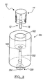
- Figure 1 is a perspective view of an armature pin assembly, in accordance with the general teachings of the present invention.
- Figure 2 is a perspective view of a die member for producing an armature pin assembly, in accordance with one embodiment of the present invention
- Figure 3 is a broken-away perspective view of the die member depicted in Fig. 2 including an optional ejection system, wherein a pin member is shown disposed in the die member, in accordance with an alternative embodiment of the present invention
- Figure 4 is a broken-away perspective view of the die member depicted in Fig. 3 wherein an amount of metallic material has been charged into the die cavity so as to envelope the exposed portion of the pin member, in accordance with an alternative embodiment of the present invention
- Figure 5 is a broken-away perspective view of the die member depicted in Fig. 4 wherein a compression member is brought into contact with the metallic material, in accordance with an alternative embodiment of the present invention
- Figure 6 is a broken-away perspective view of the die member depicted in Fig. 5 wherein the metallic material has been compressed, in accordance with an alternative embodiment of the present invention
- Figure 7 is a broken-away perspective view of the die member depicted in Fig. 6 wherein the armature pin assembly is ejected from the die member by the ejection system, in accordance with an alternative embodiment of the present invention.
- Figure 8 is a perspective view of the armature pin assembly fully ejected from the die member depicted in Fig. 7, in accordance with an alternative embodiment of the present invention.
- an armature pin assembly 10 in accordance with the general teachings of the present invention.
- the assembly 10 primarily includes a pin member 12 and an armature member 14 formed thereabout. That is, the pin member 12 is not pushed or placed in an aperture formed in the armature member 14 (as is the case in conventional armature pin assemblies), but rather the armature member 14 is caused to be shaped or otherwise formed about the pin member 12 such that the two components are fastened to one another so as to form a unitary assembly.
- pin member 12 The exact dimensions of the pin member 12 are not thought to be critical to the success of the present invention, provided that it is able to accommodate the formation of the armature member 14 thereabout and furthermore resist separation from the armature member 14 once the assembly 10 is formed.
- the pin member 12 is provided with a first end portion 16 and a second end portion 18, wherein the terms "first" and “second” are used for reference purposes only.
- first and second are used for reference purposes only.
- one end portion of the pin member 12 is submerged within the body of the armature member 14, wherein the other end portion of the pin member 12 extends outwardly from the body of the armature member 14.
- the pin member 12 is provided with a notch 20 formed along a surface thereof so as to provide an area for the material of the armature member 14 to form a locking arrangement therewith.
- the notch 20 can be continuous (e.g., forming a recessed area extending along the entire circumference of the pin member 12) or can be discontinuous (e.g., forming at least one recessed area that does not extend along the entire circumference of the pin member 12).
- a die member 100 as generally shown in Fig. 2 is employed, in accordance with one embodiment of the present invention.
- the die member 100 includes an area defining a cavity 102 and an area defining a bore 104 (e.g., a throughbore) in communication with the cavity 102.
- a bore 104 e.g., a throughbore
- the general dimensions and configurations of the cavity 102 are suitable for forming the armature member 14 of the present invention.
- FIG. 3 there is shown an optional ejection system 200 in operable association with the die member 100, in accordance with an alternative embodiment of the present invention.
- the ejection system 200 is in communication with the bore 104, e.g., at least a portion of the ejection system 200 is received within the bore 104.
- the ejection system 200 includes an ejection member 202 and an actuation system 204 that is selectively operable to cause the ejection member to deploy, i.e., to extend upwardly through the bore 104 towards the cavity 102.
- the pin member 12 is placed in the upper portion 104a of the bore 104 such that it contacts and rests upon the ejection member 202, which is in proximity to the lower portion 104b of the bore 104.
- seals, bearings, or the like can be used to either seal off a portion of the cavity 102 from the bore 104, or alternatively, to support the pin member 12.
- the tolerance between the opening 104c and the pin member 12 is substantially close, such that material in proximity thereto cannot easily enter into the bore 104.
- an amount of metallic material 300 such as but not limited to metal powder, is charged or otherwise placed into the cavity 102 such that it at least substantially envelopes or otherwise surrounds the exposed portion of the pin member 12 (in this case, the first end 16 of the pin member 12).
- the pin member 12 can be configured in any number of shapes so long as it can form a locking arrangement with the metallic material 300, e.g., in proximity to the notch 20.
- the metallic material 300 is shown as completely filling the cavity 102, it should be appreciated that less than this amount can be used, depending on the particular requirements of the assembly process.
- a compression system 400 is employed to compress the metallic material 300 to a pre-determined shape and/or configuration, e.g., an armature member 14.
- the compression system 400 includes a compression member 402 (e.g., a punch, press or the like) that is selectively operable to contact the metallic material 300, e.g., in a downwardly manner, with sufficient force so as to compress, compact, or otherwise shape the metallic material 300 into a suitable shape and/or configuration, e.g., an armature member 14.
- the assembly 10 is considered to be formed, i.e., the armature member 14 has been formed about the pin member 12 so as form a unitary member.
- the metallic material 300 infiltrates the area in proximity to the notch 20 of the pin member 12 so as to form a locking arrangement therewith, e.g., when the metallic material 300 is compressed.
- the assembly 10 is removed from the cavity 102 of the die member 100 by any number of suitable methods.
- the ejection system 200 is deployed to remove the finished assembly 10 from the cavity 102 of the die member 100.
- the ejection member 202 is deployed (e.g., upwardly towards the cavity 102) by the actuation system 204 so as to cause the ejection member 202 to contact the pin member 12 with sufficient force so as cause the assembly 10 to dislodge from the cavity 102. In this manner, manipulation of the various portions of the assembly 10 is minimized, thus potentially preventing damage thereto during the extraction process form the cavity 102.
- the assembly 10 is shown completely ejected from the die member 100, and is ready for use and/or further processing.
- the die member 10 can then be used to form additional units of the assembly 10.
- the assembly 10 can then be sintered.
- the green compacted parts are placed on a conveyer or like device that travels through a furnace or like device at a controlled rate depending on the particular alloy being sintered. This sintering process typically completes the inter-particle bonding of the metallic material to become the final part when cooled.
Landscapes
- Engineering & Computer Science (AREA)
- Power Engineering (AREA)
- Manufacturing & Machinery (AREA)
- Powder Metallurgy (AREA)
- Magnetically Actuated Valves (AREA)
- Insertion Pins And Rivets (AREA)
Abstract
Armature pin assemblies (10) and methods for forming the same are described. A first portion (18) of a pin member (12) is placed in a die cavity (102) so as to expose a second portion (16) of the pin member (12). An amount of metal powder (300) is placed into the die cavity (102) so as envelope the second portion (16) of the pin member (12). A press member (302) is then brought into contact with the metal powder (300) so as to compress the same and form an armature member (14). The pin member (12) is fastened to the armature member (14) by the press operation so as to form a unitary armature pin assembly (10).
Description
- The present invention relates generally to armatures and more particularly to armature pin assemblies wherein pins are insert molded in metal powder when the armatures are formed, and methods for forming the same.
- Electric solenoids have been used to provide a number of functions in automotive applications including, but not limited to idle speed control, exhaust gas recirculation valves, fuel vapor purge valves, and the like. The basic construction of a traditional solenoid typically includes an armature member having a pin member (e.g., a stem) member extending therefrom. The other main components of a traditional solenoid include a pole piece, coil, flux tube, and an area defining an air gap. The air gap is generally defined as a variable space between the facing surfaces of the armature and the pole piece.
- Conventionally, the armature member and the pin member were typically separately constructed, and then joined together by installing (e.g., by pushing with a press) the pin member into an orifice (e.g., a bore) formed on a surface of the armature member. Unfortunately, this methodology was not especially cost and labor efficient, and occasionally lead to damage to either the armature member and/or the pin member (e.g., bent pins). Furthermore, performance issues, such as those including misalignment of the components, material contamination, varying high press force levels, and the like, were observed in conventionally constructed armature pin assemblies.
- Accordingly, there exists a need for new and improved armature pin assemblies and methods for making the same.
- In accordance with the general teachings of the present invention, new and improved armature pin assemblies and methods for making the same are provided.
- In accordance with a first embodiment of the present invention, a method for forming an armature pin assembly is provided, comprising: (1) providing a die having a cavity formed therein; (2) providing a pin member; (3) positioning the pin member within the cavity; (4) charging an amount of metallic material into the cavity so as to envelope at least a portion of the pin member; (5) compressing the metallic material so as to form an armature member about the pin member, wherein the pin member is fastened to the armature member.
- In accordance with a second embodiment of the present invention, a system for forming an armature pin assembly is provided, comprising: (1) a die having a cavity formed therein, wherein the cavity is operable to receive a metallic material; (2) an area defining a bore formed on a surface of the die, wherein the bore is operable to at least partially receive a pin member such that the pin member is at least partially disposed within the cavity; and (3) a compression system, wherein the cavity is operable to receive a metallic material so as to at least partially envelope the pin member, wherein when the compression system is actuated it is operable to come into contact with the metallic material so as to form an armature member about the pin member, wherein the pin member is fastened to the armature member.
- In accordance with a third embodiment of the present invention, an armature pin assembly is provided, comprising: (1) a pin member; and (2) an armature member, wherein the armature member is formed by the process of: (a) providing a die having a cavity formed therein; (b) positioning the pin member within the cavity; (c) charging an amount of metallic material into the cavity so as to envelope at least a portion of the pin member; (d) compressing the metallic material so as to form the armature member about the pin member, wherein the pin member is fastened to the armature member.
- Further areas of applicability of the present invention will become apparent from the detailed description provided hereinafter. It should be understood that the detailed description and specific examples, while indicating the embodiments of the invention, are intended for purposes of illustration only and are not intended to limit the scope of the invention.
- The present invention will become more fully understood from the detailed description and the accompanying drawings, wherein:
- Figure 1 is a perspective view of an armature pin assembly, in accordance with the general teachings of the present invention;
- Figure 2 is a perspective view of a die member for producing an armature pin assembly, in accordance with one embodiment of the present invention;
- Figure 3 is a broken-away perspective view of the die member depicted in Fig. 2 including an optional ejection system, wherein a pin member is shown disposed in the die member, in accordance with an alternative embodiment of the present invention;
- Figure 4 is a broken-away perspective view of the die member depicted in Fig. 3 wherein an amount of metallic material has been charged into the die cavity so as to envelope the exposed portion of the pin member, in accordance with an alternative embodiment of the present invention;
- Figure 5 is a broken-away perspective view of the die member depicted in Fig. 4 wherein a compression member is brought into contact with the metallic material, in accordance with an alternative embodiment of the present invention;
- Figure 6 is a broken-away perspective view of the die member depicted in Fig. 5 wherein the metallic material has been compressed, in accordance with an alternative embodiment of the present invention;
- Figure 7 is a broken-away perspective view of the die member depicted in Fig. 6 wherein the armature pin assembly is ejected from the die member by the ejection system, in accordance with an alternative embodiment of the present invention; and
- Figure 8 is a perspective view of the armature pin assembly fully ejected from the die member depicted in Fig. 7, in accordance with an alternative embodiment of the present invention.
- The following description of the embodiment(s) of the present invention is merely exemplary in nature and is in no way intended to limit the invention, its application, or uses.
- Referring to the Figures generally, and more specifically to Fig. 1, there is generally shown an
armature pin assembly 10, in accordance with the general teachings of the present invention. Theassembly 10 primarily includes apin member 12 and anarmature member 14 formed thereabout. That is, thepin member 12 is not pushed or placed in an aperture formed in the armature member 14 (as is the case in conventional armature pin assemblies), but rather thearmature member 14 is caused to be shaped or otherwise formed about thepin member 12 such that the two components are fastened to one another so as to form a unitary assembly. - The exact dimensions of the
pin member 12 are not thought to be critical to the success of the present invention, provided that it is able to accommodate the formation of thearmature member 14 thereabout and furthermore resist separation from thearmature member 14 once theassembly 10 is formed. - In accordance with an aspect of the present invention, the
pin member 12 is provided with afirst end portion 16 and asecond end portion 18, wherein the terms "first" and "second" are used for reference purposes only. Without being bound to a particular theory of the operation of the present invention, one end portion of thepin member 12 is submerged within the body of thearmature member 14, wherein the other end portion of thepin member 12 extends outwardly from the body of thearmature member 14. - In accordance with another aspect of the present invention, the
pin member 12 is provided with anotch 20 formed along a surface thereof so as to provide an area for the material of thearmature member 14 to form a locking arrangement therewith. Thenotch 20 can be continuous (e.g., forming a recessed area extending along the entire circumference of the pin member 12) or can be discontinuous (e.g., forming at least one recessed area that does not extend along the entire circumference of the pin member 12). - In order to form the
assembly 10 of the present invention, adie member 100 as generally shown in Fig. 2 is employed, in accordance with one embodiment of the present invention. The diemember 100 includes an area defining acavity 102 and an area defining a bore 104 (e.g., a throughbore) in communication with thecavity 102. Without being bound to a particular theory of the operation of the present invention, the general dimensions and configurations of thecavity 102 are suitable for forming thearmature member 14 of the present invention. - Referring to Fig. 3, there is shown an
optional ejection system 200 in operable association with thedie member 100, in accordance with an alternative embodiment of the present invention. Theejection system 200 is in communication with thebore 104, e.g., at least a portion of theejection system 200 is received within thebore 104. - In accordance with an aspect of the present invention, the
ejection system 200 includes anejection member 202 and anactuation system 204 that is selectively operable to cause the ejection member to deploy, i.e., to extend upwardly through thebore 104 towards thecavity 102. - Once the
die member 100 and theoptional ejection system 200 are properly positioned, thepin member 12 is placed in the upper portion 104a of thebore 104 such that it contacts and rests upon theejection member 202, which is in proximity to the lower portion 104b of thebore 104. It should be appreciated that seals, bearings, or the like can be used to either seal off a portion of thecavity 102 from thebore 104, or alternatively, to support thepin member 12. Without being bound to a particular theory of the operation of the present invention, the tolerance between the opening 104c and thepin member 12 is substantially close, such that material in proximity thereto cannot easily enter into thebore 104. - Referring to Fig. 4, once the
pin member 12 has been properly positioned in thebore 104, an amount ofmetallic material 300, such as but not limited to metal powder, is charged or otherwise placed into thecavity 102 such that it at least substantially envelopes or otherwise surrounds the exposed portion of the pin member 12 (in this case, thefirst end 16 of the pin member 12). As previously noted, thepin member 12 can be configured in any number of shapes so long as it can form a locking arrangement with themetallic material 300, e.g., in proximity to thenotch 20. Although themetallic material 300 is shown as completely filling thecavity 102, it should be appreciated that less than this amount can be used, depending on the particular requirements of the assembly process. - Referring to Fig. 5, once a sufficient amount of the
metallic material 300 has been charged into thecavity 102, acompression system 400 is employed to compress themetallic material 300 to a pre-determined shape and/or configuration, e.g., anarmature member 14. In accordance with an aspect of the present invention, thecompression system 400 includes a compression member 402 (e.g., a punch, press or the like) that is selectively operable to contact themetallic material 300, e.g., in a downwardly manner, with sufficient force so as to compress, compact, or otherwise shape themetallic material 300 into a suitable shape and/or configuration, e.g., anarmature member 14. - Referring to Fig. 6, once the
metallic material 300 has been properly compressed, theassembly 10 is considered to be formed, i.e., thearmature member 14 has been formed about thepin member 12 so as form a unitary member. As previously noted, themetallic material 300 infiltrates the area in proximity to thenotch 20 of thepin member 12 so as to form a locking arrangement therewith, e.g., when themetallic material 300 is compressed. At this point, theassembly 10 is removed from thecavity 102 of thedie member 100 by any number of suitable methods. - Referring to Fig. 7, the
ejection system 200 is deployed to remove the finishedassembly 10 from thecavity 102 of thedie member 100. Without being bound to a particular theory of the operation of the present invention, theejection member 202 is deployed (e.g., upwardly towards the cavity 102) by theactuation system 204 so as to cause theejection member 202 to contact thepin member 12 with sufficient force so as cause theassembly 10 to dislodge from thecavity 102. In this manner, manipulation of the various portions of theassembly 10 is minimized, thus potentially preventing damage thereto during the extraction process form thecavity 102. - Referring to Fig. 8, the
assembly 10 is shown completely ejected from thedie member 100, and is ready for use and/or further processing. The diemember 10 can then be used to form additional units of theassembly 10. With respect to further processing, as theassembly 10 may be in the green state after ejection, theassembly 10 can then be sintered. By way of a non-limiting example, in a typical sintering operation, the green compacted parts are placed on a conveyer or like device that travels through a furnace or like device at a controlled rate depending on the particular alloy being sintered. This sintering process typically completes the inter-particle bonding of the metallic material to become the final part when cooled. - The description of the invention is merely exemplary in nature and, thus, variations that do not depart from the gist of the invention are intended to be within the scope of the invention. Such variations are not to be regarded as a departure from the spirit and scope of the invention.
Claims (10)
- A system for forming an armature pin assembly (10), comprising:a die (100) having a cavity (102) formed therein, wherein the cavity (102) is operable to receive a metallic material (300);an area defining a bore (104) formed on a surface of the die (100), wherein the bore (104) is operable to at least partially receive a pin member (14) such that the pin member (12) is at least partially disposed within the cavity (102); anda compression system (400);wherein the cavity (102) is operable to receive the metallic material (300) so as to at least partially envelope the pin member (12);
wherein when the compression system (400) is actuated it is operable to come into contact with the metallic material (300) so as to form an armature member (14) about the pin member (12);
wherein the pin member (12) is fastened to the armature member (14). - The invention according to claim 1, further comprising an ejection system (200), wherein the ejection system (200) is in communication with the bore (104), wherein the ejection system (200) is selectively operable to contact the pin member (12).
- The invention according to claim 1 or 2, wherein the compression system (400) comprises a punch member (402) that is selectively operable to contact the metallic material (300).
- The invention according to any previous claim, wherein a portion of the pin member (12) and the metallic material (300) are in a locking arrangement.
- The invention according to any one of claims 1 to 3, wherein the pin member (12) includes an area defining a recessed portion (20), wherein the metallic material (300) is operable to infiltrate into the recessed portion (20) so as to form a locking arrangement therebetween.
- An armature pin assembly (10), comprising:a pin member (12); andan armature member (14);wherein the armature member (14) is formed by the process of:providing a die (100) having a cavity (102) formed therein;positioning the pin member (12) within the cavity (102);charging an amount of metallic material (300) into the cavity (102) so as to envelope at least a portion of the pin member (12);compressing the metallic material (300) so as to form the armature member (14) about the pin member (12);wherein the pin member (12) is fastened to the armature member (14).
- The invention according to claim 6, further comprising an ejection system (200) operably associated with the die (100), wherein the ejection system (200) is in communication with an area defining a bore (104) formed in a surface of the cavity (102), wherein the ejection system (200) is selectively operable to contact the pin member (12).
- The invention according to claim 6 or 7, wherein the compressing step comprises selectively contacting the metallic material (300) with a punch member (402).
- The invention according to claim 6, 7 or 8, wherein the at least a portion of the pin member (12) and the metallic material (300) are in a locking arrangement.
- The invention according to claim 6, 7 or 8, wherein the pin member (12) includes an area defining a recessed portion (20), wherein the metallic material (300) is operable to infiltrate into the recessed portion (20) so as to form a locking arrangement therebetween.
Applications Claiming Priority (2)
| Application Number | Priority Date | Filing Date | Title |
|---|---|---|---|
| US62788304P | 2004-11-15 | 2004-11-15 | |
| US11/217,246 US20060101641A1 (en) | 2004-11-15 | 2005-09-01 | Armature pin and method for assembly |
Publications (1)
| Publication Number | Publication Date |
|---|---|
| EP1657729A2 true EP1657729A2 (en) | 2006-05-17 |
Family
ID=35789051
Family Applications (1)
| Application Number | Title | Priority Date | Filing Date |
|---|---|---|---|
| EP05256951A Withdrawn EP1657729A2 (en) | 2004-11-15 | 2005-11-10 | Armature pin assembly and method for assembly |
Country Status (3)
| Country | Link |
|---|---|
| US (1) | US20060101641A1 (en) |
| EP (1) | EP1657729A2 (en) |
| JP (1) | JP2006187804A (en) |
Cited By (1)
| Publication number | Priority date | Publication date | Assignee | Title |
|---|---|---|---|---|
| DE102010000245B4 (en) * | 2009-01-30 | 2018-10-31 | Denso Corporation | Structure, method and device of a mold |
Families Citing this family (3)
| Publication number | Priority date | Publication date | Assignee | Title |
|---|---|---|---|---|
| DE102006020689A1 (en) * | 2006-05-04 | 2007-11-08 | Robert Bosch Gmbh | Solenoid valve with integral anchor connection |
| JP5146341B2 (en) * | 2009-01-30 | 2013-02-20 | 株式会社デンソー | Mold structure for insert molding and molding method |
| JP5849863B2 (en) * | 2012-06-08 | 2016-02-03 | 株式会社デンソー | Manufacturing method of sintered diffusion bonding parts |
Family Cites Families (7)
| Publication number | Priority date | Publication date | Assignee | Title |
|---|---|---|---|---|
| US3648343A (en) * | 1968-12-10 | 1972-03-14 | Federal Mogul Corp | Method of making a composite high-temperature valve |
| US4353155A (en) * | 1980-06-25 | 1982-10-12 | Hillebrand Arthur N | Method for manufacturing composite powder metal parts |
| US4861546A (en) * | 1987-12-23 | 1989-08-29 | Precision Castparts Corp. | Method of forming a metal article from powdered metal |
| JP2771934B2 (en) * | 1993-02-18 | 1998-07-02 | 株式会社三協精機製作所 | Manufacturing method of bearing device |
| JPH10288085A (en) * | 1997-04-10 | 1998-10-27 | Yamaha Motor Co Ltd | Piston for internal combustion engine |
| JP3705676B2 (en) * | 1997-04-10 | 2005-10-12 | ヤマハ発動機株式会社 | Manufacturing method of piston for internal combustion engine |
| US6032570A (en) * | 1998-04-10 | 2000-03-07 | Yamaha Hatsudoki Kabushiki Kaisha | Composite piston for machine |
-
2005
- 2005-09-01 US US11/217,246 patent/US20060101641A1/en not_active Abandoned
- 2005-11-10 EP EP05256951A patent/EP1657729A2/en not_active Withdrawn
- 2005-11-10 JP JP2005325754A patent/JP2006187804A/en not_active Withdrawn
Cited By (1)
| Publication number | Priority date | Publication date | Assignee | Title |
|---|---|---|---|---|
| DE102010000245B4 (en) * | 2009-01-30 | 2018-10-31 | Denso Corporation | Structure, method and device of a mold |
Also Published As
| Publication number | Publication date |
|---|---|
| JP2006187804A (en) | 2006-07-20 |
| US20060101641A1 (en) | 2006-05-18 |
Similar Documents
| Publication | Publication Date | Title |
|---|---|---|
| CN101161521B (en) | Vehicle brake hydraulic pressure control unit | |
| JP4638644B2 (en) | Fuel injection valve | |
| CN101438365B (en) | Electromagnetic relay | |
| US6347543B1 (en) | Measuring sensor and method for its fabrication | |
| EP1657729A2 (en) | Armature pin assembly and method for assembly | |
| JP2000504091A (en) | Electromagnetic valve | |
| CN103206570B (en) | Solenoid valve | |
| JP5894119B2 (en) | Manufacturing method of surface mount inductor | |
| JP2015232544A (en) | Sensor intermediate body and manufacturing method of sensor | |
| CN113196437A (en) | Pyrotechnic device with riveted housing | |
| EP3118870A1 (en) | Manufacturing method of rotor and rotor | |
| US8042247B2 (en) | Method for assembling a two-piece punch into a tool | |
| EP3118869A1 (en) | Manufacturing method of rotor and rotor | |
| JP6684509B1 (en) | Manufacturing method of solenoid valve case | |
| KR101698077B1 (en) | Press tool | |
| CN101855033B (en) | Method and device for producing a high-pressure-tight connection and associated valve cartridge for a solenoid valve | |
| CN214305339U (en) | Electrically driven valve | |
| JPH1082478A (en) | Plunger storage sleeve fixing device for solenoid valve | |
| KR100671572B1 (en) | Contactor for car starter | |
| JP4548474B2 (en) | Electromagnetic switch | |
| CN100474479C (en) | Release armature in and electromagnetic release device | |
| JP4201330B2 (en) | Sintering method for sintered composites | |
| US5401107A (en) | Component of printing head for wire-impact type dot printer and molding method thereof | |
| US7079000B2 (en) | Spool assembly | |
| CN221463062U (en) | Solenoid valve, control system, brake assembly and vehicle |
Legal Events
| Date | Code | Title | Description |
|---|---|---|---|
| PUAI | Public reference made under article 153(3) epc to a published international application that has entered the european phase |
Free format text: ORIGINAL CODE: 0009012 |
|
| AK | Designated contracting states |
Kind code of ref document: A2 Designated state(s): AT BE BG CH CY CZ DE DK EE ES FI FR GB GR HU IE IS IT LI LT LU LV MC NL PL PT RO SE SI SK TR |
|
| AX | Request for extension of the european patent |
Extension state: AL BA HR MK YU |
|
| STAA | Information on the status of an ep patent application or granted ep patent |
Free format text: STATUS: THE APPLICATION HAS BEEN WITHDRAWN |
|
| 18W | Application withdrawn |
Effective date: 20061116 |