EP1657460A2 - Roller thrust bearing cage and manufacturing method thereof - Google Patents
Roller thrust bearing cage and manufacturing method thereof Download PDFInfo
- Publication number
- EP1657460A2 EP1657460A2 EP05024870A EP05024870A EP1657460A2 EP 1657460 A2 EP1657460 A2 EP 1657460A2 EP 05024870 A EP05024870 A EP 05024870A EP 05024870 A EP05024870 A EP 05024870A EP 1657460 A2 EP1657460 A2 EP 1657460A2
- Authority
- EP
- European Patent Office
- Prior art keywords
- cage
- thickness direction
- roller
- roller bearing
- contact
- Prior art date
- Legal status (The legal status is an assumption and is not a legal conclusion. Google has not performed a legal analysis and makes no representation as to the accuracy of the status listed.)
- Granted
Links
- 238000004519 manufacturing process Methods 0.000 title claims description 7
- 239000011347 resin Substances 0.000 claims description 15
- 229920005989 resin Polymers 0.000 claims description 15
- 239000002184 metal Substances 0.000 claims description 10
- 238000004080 punching Methods 0.000 claims description 8
- 238000003825 pressing Methods 0.000 claims description 7
- 230000015572 biosynthetic process Effects 0.000 claims description 6
- 238000005553 drilling Methods 0.000 description 13
- 230000009467 reduction Effects 0.000 description 8
- 238000006073 displacement reaction Methods 0.000 description 6
- 238000000034 method Methods 0.000 description 4
- 230000008569 process Effects 0.000 description 4
- 238000010276 construction Methods 0.000 description 3
- 239000000463 material Substances 0.000 description 3
- 230000004048 modification Effects 0.000 description 3
- 238000012986 modification Methods 0.000 description 3
- 229920002302 Nylon 6,6 Polymers 0.000 description 2
- 230000005540 biological transmission Effects 0.000 description 2
- 239000000446 fuel Substances 0.000 description 2
- 239000011159 matrix material Substances 0.000 description 2
- 230000002093 peripheral effect Effects 0.000 description 2
- 229920000049 Carbon (fiber) Polymers 0.000 description 1
- 229920003189 Nylon 4,6 Polymers 0.000 description 1
- 239000004734 Polyphenylene sulfide Substances 0.000 description 1
- 229910000831 Steel Inorganic materials 0.000 description 1
- 230000002159 abnormal effect Effects 0.000 description 1
- 229920006231 aramid fiber Polymers 0.000 description 1
- 238000005452 bending Methods 0.000 description 1
- 239000004917 carbon fiber Substances 0.000 description 1
- 230000008859 change Effects 0.000 description 1
- 238000007796 conventional method Methods 0.000 description 1
- 230000000694 effects Effects 0.000 description 1
- 239000003365 glass fiber Substances 0.000 description 1
- 238000001746 injection moulding Methods 0.000 description 1
- 229910001234 light alloy Inorganic materials 0.000 description 1
- 238000003754 machining Methods 0.000 description 1
- VNWKTOKETHGBQD-UHFFFAOYSA-N methane Chemical compound C VNWKTOKETHGBQD-UHFFFAOYSA-N 0.000 description 1
- 229920000069 polyphenylene sulfide Polymers 0.000 description 1
- 230000000717 retained effect Effects 0.000 description 1
- 239000010959 steel Substances 0.000 description 1
- 229920006259 thermoplastic polyimide Polymers 0.000 description 1
Images


Classifications
-
- F—MECHANICAL ENGINEERING; LIGHTING; HEATING; WEAPONS; BLASTING
- F16—ENGINEERING ELEMENTS AND UNITS; GENERAL MEASURES FOR PRODUCING AND MAINTAINING EFFECTIVE FUNCTIONING OF MACHINES OR INSTALLATIONS; THERMAL INSULATION IN GENERAL
- F16C—SHAFTS; FLEXIBLE SHAFTS; ELEMENTS OR CRANKSHAFT MECHANISMS; ROTARY BODIES OTHER THAN GEARING ELEMENTS; BEARINGS
- F16C33/00—Parts of bearings; Special methods for making bearings or parts thereof
- F16C33/30—Parts of ball or roller bearings
- F16C33/46—Cages for rollers or needles
- F16C33/48—Cages for rollers or needles for multiple rows of rollers or needles
-
- F—MECHANICAL ENGINEERING; LIGHTING; HEATING; WEAPONS; BLASTING
- F16—ENGINEERING ELEMENTS AND UNITS; GENERAL MEASURES FOR PRODUCING AND MAINTAINING EFFECTIVE FUNCTIONING OF MACHINES OR INSTALLATIONS; THERMAL INSULATION IN GENERAL
- F16C—SHAFTS; FLEXIBLE SHAFTS; ELEMENTS OR CRANKSHAFT MECHANISMS; ROTARY BODIES OTHER THAN GEARING ELEMENTS; BEARINGS
- F16C33/00—Parts of bearings; Special methods for making bearings or parts thereof
- F16C33/30—Parts of ball or roller bearings
- F16C33/46—Cages for rollers or needles
- F16C33/467—Details of individual pockets, e.g. shape or roller retaining means
- F16C33/4682—Details of individual pockets, e.g. shape or roller retaining means of the end walls, e.g. interaction with the end faces of the rollers
-
- F—MECHANICAL ENGINEERING; LIGHTING; HEATING; WEAPONS; BLASTING
- F16—ENGINEERING ELEMENTS AND UNITS; GENERAL MEASURES FOR PRODUCING AND MAINTAINING EFFECTIVE FUNCTIONING OF MACHINES OR INSTALLATIONS; THERMAL INSULATION IN GENERAL
- F16C—SHAFTS; FLEXIBLE SHAFTS; ELEMENTS OR CRANKSHAFT MECHANISMS; ROTARY BODIES OTHER THAN GEARING ELEMENTS; BEARINGS
- F16C33/00—Parts of bearings; Special methods for making bearings or parts thereof
- F16C33/30—Parts of ball or roller bearings
- F16C33/46—Cages for rollers or needles
- F16C33/4617—Massive or moulded cages having cage pockets surrounding the rollers, e.g. machined window cages
- F16C33/4623—Massive or moulded cages having cage pockets surrounding the rollers, e.g. machined window cages formed as one-piece cages, i.e. monoblock cages
- F16C33/4635—Massive or moulded cages having cage pockets surrounding the rollers, e.g. machined window cages formed as one-piece cages, i.e. monoblock cages made from plastic, e.g. injection moulded window cages
-
- F—MECHANICAL ENGINEERING; LIGHTING; HEATING; WEAPONS; BLASTING
- F16—ENGINEERING ELEMENTS AND UNITS; GENERAL MEASURES FOR PRODUCING AND MAINTAINING EFFECTIVE FUNCTIONING OF MACHINES OR INSTALLATIONS; THERMAL INSULATION IN GENERAL
- F16C—SHAFTS; FLEXIBLE SHAFTS; ELEMENTS OR CRANKSHAFT MECHANISMS; ROTARY BODIES OTHER THAN GEARING ELEMENTS; BEARINGS
- F16C33/00—Parts of bearings; Special methods for making bearings or parts thereof
- F16C33/30—Parts of ball or roller bearings
- F16C33/46—Cages for rollers or needles
- F16C33/54—Cages for rollers or needles made from wire, strips, or sheet metal
- F16C33/542—Cages for rollers or needles made from wire, strips, or sheet metal made from sheet metal
- F16C33/543—Cages for rollers or needles made from wire, strips, or sheet metal made from sheet metal from a single part
-
- F—MECHANICAL ENGINEERING; LIGHTING; HEATING; WEAPONS; BLASTING
- F16—ENGINEERING ELEMENTS AND UNITS; GENERAL MEASURES FOR PRODUCING AND MAINTAINING EFFECTIVE FUNCTIONING OF MACHINES OR INSTALLATIONS; THERMAL INSULATION IN GENERAL
- F16C—SHAFTS; FLEXIBLE SHAFTS; ELEMENTS OR CRANKSHAFT MECHANISMS; ROTARY BODIES OTHER THAN GEARING ELEMENTS; BEARINGS
- F16C19/00—Bearings with rolling contact, for exclusively rotary movement
- F16C19/22—Bearings with rolling contact, for exclusively rotary movement with bearing rollers essentially of the same size in one or more circular rows, e.g. needle bearings
- F16C19/30—Bearings with rolling contact, for exclusively rotary movement with bearing rollers essentially of the same size in one or more circular rows, e.g. needle bearings for axial load mainly
- F16C19/305—Bearings with rolling contact, for exclusively rotary movement with bearing rollers essentially of the same size in one or more circular rows, e.g. needle bearings for axial load mainly consisting of rollers held in a cage
-
- Y—GENERAL TAGGING OF NEW TECHNOLOGICAL DEVELOPMENTS; GENERAL TAGGING OF CROSS-SECTIONAL TECHNOLOGIES SPANNING OVER SEVERAL SECTIONS OF THE IPC; TECHNICAL SUBJECTS COVERED BY FORMER USPC CROSS-REFERENCE ART COLLECTIONS [XRACs] AND DIGESTS
- Y10—TECHNICAL SUBJECTS COVERED BY FORMER USPC
- Y10T—TECHNICAL SUBJECTS COVERED BY FORMER US CLASSIFICATION
- Y10T29/00—Metal working
- Y10T29/49—Method of mechanical manufacture
- Y10T29/49636—Process for making bearing or component thereof
- Y10T29/49643—Rotary bearing
- Y10T29/49679—Anti-friction bearing or component thereof
- Y10T29/49691—Cage making
Definitions
- the present invention relates to roller bearing cages such as needle roller thrust bearings etc. More specifically, the invention relates to roller bearing cages such as needle roller thrust bearings etc. that are used in an automatic transmission of automobile, a compressor of a vehicle air conditioner or the like.
- the thickness of the cage can be made relatively thin, so that the length of the linear contact of the projection can be made small.
- the thickness of the cage is increased in order to secure strength of the cage and also, due to limitation in shape to provide draft for releasing resin formation mold, the projection must be made to extend more in the thickness direction of the cage as compared with the metal cage. Accordingly, the difference in the contact speeds between the projection and the end face of the roller is further increased, and the drilling wear as discussed above becomes more considerable.
- One of the problems to be solved in the present invention is to obtain weight saving and reduction in rotational torque in a roller thrust bearing while suppressing drilling wear as described foregoing in either cases that the cage is made of metal or resin.
- the invention provides a roller bearing cage that can contribute to further weight saving and reduction in rotational torque of the roller bearing while having significant effect on suppressing the drilling wear.
- the invention provides a roller bearing cage comprising:
- a projection is formed at least at the circumferential central part on the inner face of the cage pocket (namely, circumferential side face of the cage pocket).
- the projection has a shape extending in the thickness direction to secure draft for releasing the cage from the formation mold. More specifically, the projection extends in the thickness direction at the circumferential central portion and a flat portion formed in the central part of the projection linearly extends in the thickness direction.
- the projection includes a contact portion that is brought into a contact with a central portion or a vicinity thereof on the end face of the roller, and a non-contact portion that is adjacent to the contact portion in the thickness direction and that is not brought into contact with the end face of the roller. Therefore, the projection is configured to reduce the contact area between the projection and the roller end face. As a result, according to the invention, the drilling wear due to the liner contact between the inner face of the cage pocket and the roller end face is reduced and it is possible to obtain a reduction in rotational torque.
- the cage is made of resin for weight saving
- the cage thickness is made thick to secure the cage strength and the projection is made long in the thickness direction of the cage
- only the contact portion formed in a part of the projection is brought into linear contact with the roller end face. Accordingly it is possible to reduce or suppress the drilling wear and to obtain simultaneously the weight saving and reduction in rotational torque of the bearing in which the cage of the invention is mounted for low fuel consumption of an automobile.
- the flat portion may have a flat length that is at least almost equivalent to a displaceable distance of the cage in the thickness direction.
- the contact portion assuredly keeps a state that the contact potion is always brought into contact with the central portion on the roller end face, so that the roller in motion is pivotally supported and its smooth rotational motion is maintained.
- the non-contact portion may include a chamfered portion formed on an edge of the projection in the thickness direction of the cage.
- the contact portion may include a flat portion having a flat face in the thickness direction of the cage in a central part of the projection.
- a pair of the chamfered portions may be formed on the opposite edges of the projection in the thickness direction of the cage.
- the cage of the invention may be a needle roller bearing cage or a roller bearing cage other than needle roller bearing.
- the cage of the invention does not limit type of the bearing to which the cage is applied as far as the bearing is provided with a cage.
- the cage may be made of resin or may be made of metal. If the cage is made of resin, the thickness of the cage becomes relatively large. Therefore, the invention is specifically suitable for sufficiently suppressing the drilling wear in such the resin cage. If the cage is made of metal, although the cage thickness is relatively small, the invention is also suitable for suppressing the drilling wear by providing the non-contact portion in a part of the projection.
- Second aspect of the invention is provided with a manufacturing method of a roller bearing cage including a cage main body formed with an annular plate; and a plurality of cage pockets opened so as to be arranged along a circumferential direction on the cage main body for retaining rollers having flat end faces, comprising the steps of:
- the drilling wear due to a contact between the inner face of the cage pocket and the roller end face is reduced and it is possible to obtain weight saving and reduction in rotational torque in the cage.
- roller bearing cages according to the embodiments of the invention.
- the roller bearing cages of the embodiments are applied to needle roller bearing cages, the invention is applicable other types of roller bearing cages.
- Figs. 1 through 4 show the cage of Embodiment 1.
- Fig. 1 is a partial plan view showing a roller bearing cage
- Fig. 2 is an enlarged plan view showing a vicinity of a cage pocket in Fig. 1
- Fig. 3 is a sectional view taken on line III-III of Fig. 2
- Fig. 4 is an explanatory view showing a displaceable amount in a thickness direction of the cage.
- a cage 10 according to Embodiment 1 as shown in Fig. 1 includes a ring plate 11 having an annular shape and formed of a resin, on which cage pockets 12 for retaining rollers are formed at plural positions along circumferential direction.
- the cage pockets 12 are opened and arranged in a radial manner around the center of the cage at a constant pitch of a predetermined angle.
- Each cage pocket 12 is formed in a rectangular shape elongated slightly in the radial direction from the center of the cage in accordance with the roller length, and houses a roller 13 having flat end faces to obtain a large load capacity.
- Resin material for the ring plate 11 is not specifically limited if it is suitable in terms of the cage performance and cage strength etc.
- the cage may be constituted by a material in which polyamide 66, polyamide 46, polyphenylene sulfide, thermoplastic polyimide or the like is served as matrix, and glass fiber, carbon fiber, aramid fiber or the like may be added in the matrix to improve the strength.
- Polyamide 66 is particularly suitable for material of the cage because it has excellent properties such as tensile strength and bending stiffness and has small coefficient of linear expansion.
- Projections 14 are formed on opposite radial inner faces 12a to reduce frictional resistance by contact between the inner faces 12a and end faces 13a of the roller 13.
- Embodiment 1 is generally characterized by the shape of the projections 14. Referring to Figs. 2 and 3, the shape of one of the projections 14 will be described in detail below.
- the projection 14 has a shape projecting into the cage pocket 12 at a central part in the circumferential direction on the inner surface 12a of the cage pocket 12 over a thickness direction (height direction) of the cage 10.
- the projection 14 has a curved surface shape such as semi-circle or semi-ellipse, so that the projection 14 is brought into a point contact with a circumferential central portion 13b on the roller end face 13a.
- the projection 14 extends in the thickness direction of the cage 10 between opposite edges of the inner surface 12a of the cage pocket 12.
- Opposite edges of the projection 14 are chamfered, so that a sectional shape of the projection 14 is constituted by chamfered portions (non-contact portions) 14a on the opposite edges and a flat portion (contact portion) 14b in the center part.
- the chamfered portions 14a are formed adjacent to the flat portion 14b in the thickness direction.
- Sectional shape of the chamfered portions 14a is not limited to straight, and it may be formed with a curved shape such as rounded shape.
- Chamfering angle of the chamfered portions 14a is not specifically limited.
- the opposite edges of the projection 14 may be formed in chamfered shapes serving as draft.
- the chamfered portions 14a of the projection 14 forms non-contact portions that do not contact with the end face 13a of the roller 13.
- the non-contact portions are formed in a chamfered shape (rounded or tapered shape) in Embodiment 1, the non-contact portions may include a shape formed in a stepped manner with respect to the flat portion 14b.
- the non-contact portions may have a shape so as not to contact with the end face 13a of the roller 13, however, the shape of the chamfered portions 14a is preferable to serve as draft for being released from the mold after resin formation. By adjusting the chamfering angle of the chamfered portions 14a, a preferable draft for being released from the mold can be obtained.
- the flat portion 14b constitutes a maximum projected part of the projection 14 into the cage pocket 12 so as to pivotally support the roller 13 which is seated in the cage pocket 12 by contacting with a central portion 13c in the thickness direction of the cage 10 on the end face 13a of the roller 13.
- the flat portion 14b of the projection 14 constitutes a contact portion that is brought into contact with a region including the central portion 13c on the end face 13a of the roller 13 so as to be in parallel with each other.
- the shape of the contact portion is constituted by a shape that is flat and in parallel with the end face 13a of the roller 13 in Embodiment 1, the contact portion may contain a slightly rounded shape at boundaries to the chamfered portions 14a so as to form continuity therebetween. It is preferable to avoid unnecessary frictional contact with the end face 13a of the roller 13 at the boundaries by forming continuity in shape change between the flat portion 14b and the chamfered portions 14a.
- the cage 10 of Embodiment 1 is mounted between an outer peripheral housing member and an inner peripheral side shaft member as a roller thrust bearing without race ring or a roller thrust bearing with race ring, it is assumed that the cage 10 is displaceable at a distance L0 in the thickness direction.
- the cage 10 is displaceable up to a first displacement position P1 shown with chain line on one side in the thickness direction
- the cage 10 is displaceable up to a second displacement position P2 shown with chain double dashed line on the other side in the thickness direction.
- the distance between the positions P1 and P2 makes L0.
- the flat portion 14b has a flat length L1 that is at least almost equivalent to the above-described displaceable distance L0 in the thickness direction of the cage 10.
- the flat portion 14b has a flat length L1 that is slightly longer than the above-described displaceable distance L0 in the thickness direction of the cage 10.
- the flat length L1 of the flat portion 14b should be made as short as possible, so as to reduce frictional resistance by contact to the roller end face 13a and to reduce difference in circumferential speeds at the contact portion between the flat portion 14b and the roller end face 13a.
- the flat length of the flat portion 14b should be made with a small length close to zero preferably.
- the projection 14 is preferably brought into almost point contact, while not pure point contact, to the central portion 13c in the thickness direction of the cage 10 on the end face 13a of the roller 13.
- the cage 10 is normally displaced in the thickness direction, the flat length L1 of the flat portion 14b is made almost equivalent to the displaceable distance L0 of the cage 10 in the thickness direction thereof in Embodiment 1.
- an end of the flat portion 14b of the projection 14 that is located on the other side in the thickness direction corresponds to the central portion 13c in the thickness direction on the roller end face 13a
- another end of the flat portion 14b of the projection 14 that is located on one side in the thickness direction corresponds to the central portion 13c in the thickness direction on the roller end face 13a.
- the flat portion 14c can be in contact with the central portion 13c in the thickness direction on the roller end face 13a in any case that the cage 10 is displaced at any position in the thickness direction.
- the flat portion 14b assuredly keeps a state that the flat portion 147b is always brought into contact with the central portion 13c in the thickness direction on the roller end face 13a, so that the roller 13 in motion is pivotally supported and its smooth rotational motion is maintained.
- the flat portion 14b to contact with the central portion 13c of the roller end face 13a at a part of the projection 14 and the flat length of the flat portion 14b is formed to as to be at least almost equivalent to the displaceable distance in the thickness direction of the cage 10. Hence only the part of the projection 14 is brought into linear contact with the central portion 13c in the thickness direction of the cage 10 on the roller end face 13a, so that a drilling wear is much reduced by reducing the area of the linear contact.
- the cage 10 even if the cage 10 is made of resin and its thickness becomes relatively large, only the flat portion 14b that is the part of the projection 14 is brought into linear contact with the roller end face 13a. Hence, the drilling wear is suppressed and it is possible to reduce a rotational torque to be required.
- Figs. 5 through 8D show the cage according to Embodiment 2.
- Fig. 5 is a plan view showing a roller bearing cage
- Fig. 6 is an enlarged plan view showing a vicinity of a cage pocket in Fig. 5
- Fig. 7 is a sectional view taken on line VII-VII of Fig. 6
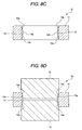
- Figs. 8A through 8C show a process forming chamfered portions of the cage of Fig. 5
- Fig. 8D shows a modification of the process forming the chamfered portions of the cage.
- the cage 10 shown in these drawings includes a ring plate 11 formed from a metal like light alloy etc. or a steel plate by punching.
- the ring plate 11 has a W-shaped section in the radial direction and plurality of roller retaining cage pockets 12 are formed in a radial manner around the center of the cage 10.
- the cage pockets 12 are opened and formed simultaneously at the forming of the ring plate 11 by punching.
- a roller retaining portion 12b is formed on a circumferential inner face 12a.
- a projection 14 is formed similarly to Embodiment 1.
- the projection 14 has a shape projecting into the cage pocket 12 at a central part in the circumferential direction on the inner surface 12a of the cage pocket 12 over a thickness direction of the cage 10. Opposite edges of the projection 14 in the thickness direction are chamfered, so that a sectional shape of the projection 14 is constituted by chamfered portions (non-contact portions) 14a on the opposite edges and a flat portion (contact portion) 14b that is flat in the thickness direction.
- the flat portion 14b is constituted to pivotally support a roller 13 which is seated in the cage pocket 12 by contacting with a central portion 13c in the thickness direction on an end face 13a of the roller 13.
- the flat portion 14b of the projection 14 has a flat length L1 that is at least almost equivalent to a displaceable distance L0 in the thickness direction of the cage 10. Accordingly, in a case that the cage 10 is displaced to the first displacement position on one side in the thickness direction, or in a case that the cage 10 is displaced to the second displacement position on the other side in the thickness direction, the flat portion 14b corresponds to the central portion 13c in the thickness direction on the roller end face 13a. As a result, the flat portion 14c can be in contact with the central portion 13c in the thickness direction on the roller end face 13a in any case that the cage 10 is displaced at any position in the thickness direction.
- the chamfered portions 14a may be formed by pressing an radial inner face of the cage pocket 12 formed by punching with an annular press jig 15 that is provided with a pressing face 15a having an angle corresponding to an chamfering angle of the chamfered portions 14a.
- the cage 10 and the press jig 15 are disposed in an opposite manner, and then opposite edges of the projection 14 in the thickness direction of the cage 10 are pressed with the press jig 15.
- the chamfered portions 14a are formed on the opposite edges of the projection 14 of the cage 10 as shown in Fig. 8C.
- the flat portion 14b is formed simultaneously to the formation of the chamferedportions 14a.
- a pair of the press jigs 15 may be disposed in an opposite manner interposing the cage 10, and the opposite edges of the projection 14 in the thickness direction may be simultaneously pressed with the press jigs 15, so that the chamfered portions 14a and the flat portion 14b are simultaneously formed.
Abstract
Description
- The present invention relates to roller bearing cages such as needle roller thrust bearings etc. More specifically, the invention relates to roller bearing cages such as needle roller thrust bearings etc. that are used in an automatic transmission of automobile, a compressor of a vehicle air conditioner or the like.
- Trend for low fuel consumption of automobile in recent years has increased demands for further weight saving and further reduction of rotational torque to the roller thrust bearings that are mounted in various parts such as automatic transmission in the vehicle more and more. For weight saving, a cage made of resin has been proposed. For reduction of rotational torque, there has been proposed a cage in which projections are formed at central parts in the circumferential direction on opposite inner faces of the cage pocket over the thickness direction of the cage (width direction of assembly) to pivotally support a roller by contacting with circumferential central portions on end faces of the roller on inner and outer circumferential sides (See Japanese Patent Publication No. JP 2004-211824A.). In the cage disclosed in JP 2004-211824A, by providing the projections in opposite inner faces of the cage pocket, the reduction of rotational torque can be accomplished because contact area between the opposite inner faces and the end faces of the roller is reduced. However, in such the cage, due to limitation in machining shape of punching die for the cage pocket, the projections must extends over the thickness direction of the cage. Accordingly, a linear contact area between the projections and the end faces of the roller in the thickness direction is increased, and contact portions are exposed to a large difference in contact speeds in the thickness direction. As a result, in such the structure, abnormal wear (drilling wear) can easily occur on the inner faces of the cage pocket. As the cage disclosed in JP 2004-211824A is made of metal, the thickness of the cage can be made relatively thin, so that the length of the linear contact of the projection can be made small. However, if the cage is made of resin for saving weight, the thickness of the cage is increased in order to secure strength of the cage and also, due to limitation in shape to provide draft for releasing resin formation mold, the projection must be made to extend more in the thickness direction of the cage as compared with the metal cage. Accordingly, the difference in the contact speeds between the projection and the end face of the roller is further increased, and the drilling wear as discussed above becomes more considerable.
- One of the problems to be solved in the present invention is to obtain weight saving and reduction in rotational torque in a roller thrust bearing while suppressing drilling wear as described foregoing in either cases that the cage is made of metal or resin. In particular, in a case that the thickness of the cage must be large because the cage is made of resin, or the like, the invention provides a roller bearing cage that can contribute to further weight saving and reduction in rotational torque of the roller bearing while having significant effect on suppressing the drilling wear.
- The invention provides a roller bearing cage comprising:
- a cage main body formed with an annular plate; and
- a plurality of cage pockets opened so as to be arranged along a circumferential direction on the cage main body for retaining rollers having flat end faces;
- wherein a projection to pivotally support an end face of the corresponding roller is projected at a central portion in the circumferential direction on a radial inner face of each cage pocket,
- the projection extends in a thickness direction of the cage main body, and includes a contact portion that is brought into a contact with a central portion or a vicinity thereof on the end face of the roller, and a non-contact portion that is adjacent to the contact portion in the thickness direction and that is not brought into contact with the end face of the roller.
- In the cage according to the invention, in order to secure large load capacity to the roller seated in the cage pocket, the roller having flat end faces is retained, and in order to reduce frictional resistance by contact between the inner faces of the cage pocket and the end faces of the roller, a projection is formed at least at the circumferential central part on the inner face of the cage pocket (namely, circumferential side face of the cage pocket). The projection has a shape extending in the thickness direction to secure draft for releasing the cage from the formation mold. More specifically, the projection extends in the thickness direction at the circumferential central portion and a flat portion formed in the central part of the projection linearly extends in the thickness direction. By such the structure, if non-contact portion is not formed, the contact area between the projection on the inner face of the cage pocket and the end face of the roller would be formed linearly in the thickness direction causing circumferential speed difference. In such a state, a drilling wear can easily occur.
- Under foregoing circumstances, according to the invention, the projection includes a contact portion that is brought into a contact with a central portion or a vicinity thereof on the end face of the roller, and a non-contact portion that is adjacent to the contact portion in the thickness direction and that is not brought into contact with the end face of the roller. Therefore, the projection is configured to reduce the contact area between the projection and the roller end face. As a result, according to the invention, the drilling wear due to the liner contact between the inner face of the cage pocket and the roller end face is reduced and it is possible to obtain a reduction in rotational torque. Further, according to the invention, in a case that the cage is made of resin for weight saving, even if the cage thickness is made thick to secure the cage strength and the projection is made long in the thickness direction of the cage, only the contact portion formed in a part of the projection is brought into linear contact with the roller end face. Accordingly it is possible to reduce or suppress the drilling wear and to obtain simultaneously the weight saving and reduction in rotational torque of the bearing in which the cage of the invention is mounted for low fuel consumption of an automobile.
- Further, in a case that a semi-circle projection is formed on the inner face of the cage pocket to pivotally support the central portion on the roller end face by almost point contact, the difference in the circumferential speeds does not occur at the contact area between the projection and the roller end face. However, if the cage is moved in the thickness direction thereof, the projection and the central portion on the roller end face are offset to each other and non-contact therebetween occurs and the projection cannot pivotally support the roller. On the other hand, according to the invention, the flat portion may have a flat length that is at least almost equivalent to a displaceable distance of the cage in the thickness direction. By such the construction, even if the cage is moved in the thickness direction, the contact portion assuredly keeps a state that the contact potion is always brought into contact with the central portion on the roller end face, so that the roller in motion is pivotally supported and its smooth rotational motion is maintained.
- The non-contact portion may include a chamfered portion formed on an edge of the projection in the thickness direction of the cage. The contact portion may include a flat portion having a flat face in the thickness direction of the cage in a central part of the projection. A pair of the chamfered portions may be formed on the opposite edges of the projection in the thickness direction of the cage.
- The cage of the invention may be a needle roller bearing cage or a roller bearing cage other than needle roller bearing. The cage of the invention does not limit type of the bearing to which the cage is applied as far as the bearing is provided with a cage. The cage may be made of resin or may be made of metal. If the cage is made of resin, the thickness of the cage becomes relatively large. Therefore, the invention is specifically suitable for sufficiently suppressing the drilling wear in such the resin cage. If the cage is made of metal, although the cage thickness is relatively small, the invention is also suitable for suppressing the drilling wear by providing the non-contact portion in a part of the projection.
- Second aspect of the invention is provided with a manufacturing method of a roller bearing cage including a cage main body formed with an annular plate; and a plurality of cage pockets opened so as to be arranged along a circumferential direction on the cage main body for retaining rollers having flat end faces, comprising the steps of:
- punching an annular plate from a metal;
- forming a plurality of cage pockets on the annular plate;
- pressing an edge of one of the cage pockets in a thickness direction of the annular plate on a side face of the cage pocket with a press jig having a pressing face of a predetermined shape to form a chamfered portion.
- By such a manufacturing method of a roller bearing cage, a cage having the above-described construction and advantages can be obtained.
- According to the invention, the drilling wear due to a contact between the inner face of the cage pocket and the roller end face is reduced and it is possible to obtain weight saving and reduction in rotational torque in the cage.
-
- Fig. 1 is a partial plan view showing a roller bearing cage according to Embodiment 1;
- Fig. 2 is an enlarged plan view showing a vicinity of a cage pocket in Fig. 1;
- Fig. 3 is a sectional view taken on line III-III of Fig. 2;
- Fig. 4 is an explanatory view showing a displaceable amount in the thickness direction of the cage;
- Fig. 5 is a partial plan view showing a roller bearing cage according to Embodiment 2;
- Fig. 6 is an enlarged plan view showing a vicinity of a cage pocket in Fig. 5;
- Fig. 7 is a sectional view taken on line VII-VII of Fig. 6; and
- Figs. 8A through 8C show a process forming chamfered portions of the cage of Fig. 5, and Fig. 8D shows a modification of the process forming the chamfered portions of the cage.
- Referring to the drawings, the description will be made on the roller bearing cages according to the embodiments of the invention. Although the roller bearing cages of the embodiments are applied to needle roller bearing cages, the invention is applicable other types of roller bearing cages.
- Figs. 1 through 4 show the cage of Embodiment 1. Fig. 1 is a partial plan view showing a roller bearing cage, Fig. 2 is an enlarged plan view showing a vicinity of a cage pocket in Fig. 1, Fig. 3 is a sectional view taken on line III-III of Fig. 2, and Fig. 4 is an explanatory view showing a displaceable amount in a thickness direction of the cage.
- A
cage 10 according to Embodiment 1 as shown in Fig. 1 includes aring plate 11 having an annular shape and formed of a resin, on which cage pockets 12 for retaining rollers are formed at plural positions along circumferential direction. The cage pockets 12 are opened and arranged in a radial manner around the center of the cage at a constant pitch of a predetermined angle. Eachcage pocket 12 is formed in a rectangular shape elongated slightly in the radial direction from the center of the cage in accordance with the roller length, and houses aroller 13 having flat end faces to obtain a large load capacity. Resin material for thering plate 11 is not specifically limited if it is suitable in terms of the cage performance and cage strength etc. For example, the cage may be constituted by a material in which polyamide 66, polyamide 46, polyphenylene sulfide, thermoplastic polyimide or the like is served as matrix, and glass fiber, carbon fiber, aramid fiber or the like may be added in the matrix to improve the strength. Polyamide 66 is particularly suitable for material of the cage because it has excellent properties such as tensile strength and bending stiffness and has small coefficient of linear expansion. - A roller retaining portion(not-shown) for preventing the
roller 13 from running off on a circumferentialinner face 12a of thecage pocket 12.Projections 14 are formed on opposite radial inner faces 12a to reduce frictional resistance by contact between theinner faces 12a and end faces 13a of theroller 13. - Embodiment 1 is generally characterized by the shape of the
projections 14. Referring to Figs. 2 and 3, the shape of one of theprojections 14 will be described in detail below. Theprojection 14 has a shape projecting into thecage pocket 12 at a central part in the circumferential direction on theinner surface 12a of thecage pocket 12 over a thickness direction (height direction) of thecage 10. Theprojection 14 has a curved surface shape such as semi-circle or semi-ellipse, so that theprojection 14 is brought into a point contact with a circumferentialcentral portion 13b on theroller end face 13a. Theprojection 14 extends in the thickness direction of thecage 10 between opposite edges of theinner surface 12a of thecage pocket 12. Opposite edges of theprojection 14 are chamfered, so that a sectional shape of theprojection 14 is constituted by chamfered portions (non-contact portions) 14a on the opposite edges and a flat portion (contact portion) 14b in the center part. In other words, thechamfered portions 14a are formed adjacent to theflat portion 14b in the thickness direction. Sectional shape of the chamferedportions 14a is not limited to straight, and it may be formed with a curved shape such as rounded shape. Chamfering angle of the chamferedportions 14a is not specifically limited. In a case that thecage 10 is formed by a conventional method such as injection molding, the opposite edges of theprojection 14 may be formed in chamfered shapes serving as draft. Therefore, thecage 10 after formed can be easily drawn from the resin formation mold. Thechamfered portions 14a of theprojection 14 forms non-contact portions that do not contact with theend face 13a of theroller 13. Although the non-contact portions are formed in a chamfered shape (rounded or tapered shape) in Embodiment 1, the non-contact portions may include a shape formed in a stepped manner with respect to theflat portion 14b. The non-contact portions may have a shape so as not to contact with theend face 13a of theroller 13, however, the shape of the chamferedportions 14a is preferable to serve as draft for being released from the mold after resin formation. By adjusting the chamfering angle of the chamferedportions 14a, a preferable draft for being released from the mold can be obtained. - The
flat portion 14b constitutes a maximum projected part of theprojection 14 into thecage pocket 12 so as to pivotally support theroller 13 which is seated in thecage pocket 12 by contacting with acentral portion 13c in the thickness direction of thecage 10 on theend face 13a of theroller 13. Theflat portion 14b of theprojection 14 constitutes a contact portion that is brought into contact with a region including thecentral portion 13c on theend face 13a of theroller 13 so as to be in parallel with each other. Although the shape of the contact portion is constituted by a shape that is flat and in parallel with theend face 13a of theroller 13 in Embodiment 1, the contact portion may contain a slightly rounded shape at boundaries to thechamfered portions 14a so as to form continuity therebetween. It is preferable to avoid unnecessary frictional contact with theend face 13a of theroller 13 at the boundaries by forming continuity in shape change between theflat portion 14b and thechamfered portions 14a. - Referring to Fig. 4, the
flat portion 14b is described more in detailed. In a case that thecage 10 of Embodiment 1 is mounted between an outer peripheral housing member and an inner peripheral side shaft member as a roller thrust bearing without race ring or a roller thrust bearing with race ring, it is assumed that thecage 10 is displaceable at a distance L0 in the thickness direction. In other words, thecage 10 is displaceable up to a first displacement position P1 shown with chain line on one side in the thickness direction, on the other hand, thecage 10 is displaceable up to a second displacement position P2 shown with chain double dashed line on the other side in the thickness direction. The distance between the positions P1 and P2 makes L0. Theflat portion 14b has a flat length L1 that is at least almost equivalent to the above-described displaceable distance L0 in the thickness direction of thecage 10. Preferably, theflat portion 14b has a flat length L1 that is slightly longer than the above-described displaceable distance L0 in the thickness direction of thecage 10. Preferably, the flat length L1 of theflat portion 14b should be made as short as possible, so as to reduce frictional resistance by contact to theroller end face 13a and to reduce difference in circumferential speeds at the contact portion between theflat portion 14b and theroller end face 13a. In a case that thecage 10 is not displaced in the thickness direction, the flat length of theflat portion 14b should be made with a small length close to zero preferably. Namely, theprojection 14 is preferably brought into almost point contact, while not pure point contact, to thecentral portion 13c in the thickness direction of thecage 10 on theend face 13a of theroller 13. However, thecage 10 is normally displaced in the thickness direction, the flat length L1 of theflat portion 14b is made almost equivalent to the displaceable distance L0 of thecage 10 in the thickness direction thereof in Embodiment 1. - Accordingly, in the
cage 10 of Embodiment 1, in a case that thecage 10 is displaced to the first displacement position P1 on one side in the thickness direction, an end of theflat portion 14b of theprojection 14 that is located on the other side in the thickness direction corresponds to thecentral portion 13c in the thickness direction on theroller end face 13a, whereas, in a case that thecage 10 is displaced to the second displacement position P2 on the other side in the thickness direction, another end of theflat portion 14b of theprojection 14 that is located on one side in the thickness direction corresponds to thecentral portion 13c in the thickness direction on theroller end face 13a. As a result, the flat portion 14c can be in contact with thecentral portion 13c in the thickness direction on theroller end face 13a in any case that thecage 10 is displaced at any position in the thickness direction. Hence, theflat portion 14b assuredly keeps a state that the flat portion 147b is always brought into contact with thecentral portion 13c in the thickness direction on theroller end face 13a, so that theroller 13 in motion is pivotally supported and its smooth rotational motion is maintained. - In the
cage 10 having the above described construction, theflat portion 14b to contact with thecentral portion 13c of theroller end face 13a at a part of theprojection 14 and the flat length of theflat portion 14b is formed to as to be at least almost equivalent to the displaceable distance in the thickness direction of thecage 10. Hence only the part of theprojection 14 is brought into linear contact with thecentral portion 13c in the thickness direction of thecage 10 on theroller end face 13a, so that a drilling wear is much reduced by reducing the area of the linear contact. - Further, in the
cage 10, even if thecage 10 is made of resin and its thickness becomes relatively large, only theflat portion 14b that is the part of theprojection 14 is brought into linear contact with theroller end face 13a. Hence, the drilling wear is suppressed and it is possible to reduce a rotational torque to be required. - Figs. 5 through 8D show the cage according to Embodiment 2. Fig. 5 is a plan view showing a roller bearing cage, Fig. 6 is an enlarged plan view showing a vicinity of a cage pocket in Fig. 5, Fig. 7 is a sectional view taken on line VII-VII of Fig. 6, Figs. 8A through 8C show a process forming chamfered portions of the cage of Fig. 5, and Fig. 8D shows a modification of the process forming the chamfered portions of the cage.
- Referring to Figs. 5 through 7, the
cage 10 shown in these drawings includes aring plate 11 formed from a metal like light alloy etc. or a steel plate by punching. Thering plate 11 has a W-shaped section in the radial direction and plurality of roller retaining cage pockets 12 are formed in a radial manner around the center of thecage 10. The cage pockets 12 are opened and formed simultaneously at the forming of thering plate 11 by punching. Further, aroller retaining portion 12b is formed on a circumferentialinner face 12a. On a radialinner face 12a, aprojection 14 is formed similarly to Embodiment 1. - Similarly to Embodiment 1, the
projection 14 has a shape projecting into thecage pocket 12 at a central part in the circumferential direction on theinner surface 12a of thecage pocket 12 over a thickness direction of thecage 10. Opposite edges of theprojection 14 in the thickness direction are chamfered, so that a sectional shape of theprojection 14 is constituted by chamfered portions (non-contact portions) 14a on the opposite edges and a flat portion (contact portion) 14b that is flat in the thickness direction. Theflat portion 14b is constituted to pivotally support aroller 13 which is seated in thecage pocket 12 by contacting with acentral portion 13c in the thickness direction on anend face 13a of theroller 13. - The
flat portion 14b of theprojection 14 has a flat length L1 that is at least almost equivalent to a displaceable distance L0 in the thickness direction of thecage 10. Accordingly, in a case that thecage 10 is displaced to the first displacement position on one side in the thickness direction, or in a case that thecage 10 is displaced to the second displacement position on the other side in the thickness direction, theflat portion 14b corresponds to thecentral portion 13c in the thickness direction on theroller end face 13a. As a result, the flat portion 14c can be in contact with thecentral portion 13c in the thickness direction on theroller end face 13a in any case that thecage 10 is displaced at any position in the thickness direction. - In the
cage 10 according to the above-described Embodiment 2, similarly to Embodiment 1, only the part of theprojection 14 is brought into linear contact with thecentral portion 13c in the thickness direction of thecage 10 on theroller end face 13a, so that a drilling wear is much reduced by reducing the area of the linear contact. - The
chamfered portions 14a may be formed by pressing an radial inner face of thecage pocket 12 formed by punching with anannular press jig 15 that is provided with apressing face 15a having an angle corresponding to an chamfering angle of the chamferedportions 14a. In other words, as shown in Fig. 8A, thecage 10 and thepress jig 15 are disposed in an opposite manner, and then opposite edges of theprojection 14 in the thickness direction of thecage 10 are pressed with thepress jig 15. Thus, thechamfered portions 14a are formed on the opposite edges of theprojection 14 of thecage 10 as shown in Fig. 8C. Theflat portion 14b is formed simultaneously to the formation of thechamferedportions 14a. - Incidentally, as shown in Fig. 8D, a pair of the press jigs 15 may be disposed in an opposite manner interposing the
cage 10, and the opposite edges of theprojection 14 in the thickness direction may be simultaneously pressed with the press jigs 15, so that thechamfered portions 14a and theflat portion 14b are simultaneously formed. - The invention is not limited by the foregoing embodiments. The invention should include various changes or modification within the scope of the claims.
Claims (15)
- A roller bearing cage comprising:a cage main body formed with an annular plate; anda plurality of cage pockets opened so as to be arranged along a circumferential direction on the cage main body for retaining rollers having flat end faces;wherein a projection to pivotally support an end face of the corresponding roller is projected at a central part in the circumferential direction on a radial inner face of each cage pocket,the projection extends in a thickness direction of the cage main body, and includes a contact portion that is brought into a contact with a central portion or a vicinity thereof on the end face of the roller, and a non-contact portion that is adjacent to the contact portion in the thickness direction and that is not brought into contact with the end face of the roller.
- A roller bearing cage according to claim 1, wherein the flat portion has a flat length that is at least almost equivalent to a displaceable distance in the thickness direction of the cage main body.
- A roller bearing cage according to claim 1 or claim 2, wherein the non-contact portion is provided with a chamfered portion formed in an edge of the projection in the thickness direction, and the contact portion is provided with a flat portion formed in a central part of the projection so as to be flat in the thickness direction.
- A roller bearing cage according to claim 3, wherein the chamfered portion is formed in a tapered shape.
- A roller bearing cage according to claim 3, wherein the chamfered portion is formed in a curved shape.
- A roller bearing cage according to claim 1 or claim 2, wherein a flat portion is formed in a central part of the projection so as to be linearly extending in the thickness direction.
- A roller bearing cage according to claim 1 or claim 2, wherein a pair of the non-contact portions are adjacently formed on opposite sides of the contact portion in the thickness direction.
- A roller bearing cage according to claim 1 or claim 2, wherein the cage pockets are formed in a rectangular shape in plane respectively, and are arranged in a radial manner at contact pitch of predetermined angle on the annular plate.
- A roller bearing cage according to claim 1 or claim 2, wherein a roller retaining portion is formed on a circumferential side face of at least one of the cage pockets.
- A roller bearing cage according to claim 1 or claim 2, wherein the cage main body is provided with the single annular plate that is formed by resin formation.
- A roller bearing cage according to claim 1 or claim 2, wherein the cage main body is provided with the single annular plate that is formed from a metal sheet by punching.
- A manufacturing method of a roller bearing cage including a cage main body formed with an annular plate; and a plurality of cage pockets opened so as to be arranged along a circumferential direction on the cage main body for retaining rollers having flat end faces, comprising the steps of:punching an annular plate from a metal;forming a plurality of cage pockets on the annular plate;pressing an edge of one of the cage pockets in a thickness direction of the annular plate on a side face of the cage pocket with a press jig having a pressing face of a predetermined shape to form a chamfered portion.
- A manufacturing method of a roller bearing cage according to claim 12, wherein the cage pockets are simultaneously formed at punching the annular plate from the metal.
- A manufacturing method of a roller bearing cage according to claim 12, wherein a flat portion is formed simultaneously at forming the chamfered portion by pressing the edge of the cage pocket in the thickness direction on side face of the cage pocket with the press jig.
- A manufacturing method of a roller bearing cage according to claim 12, wherein opposite edges of the cage pocket in the thickness direction are simultaneously pressed with a pair of the press jigs, so that a flat portion and a pair of the chamfered portions adjacent to the flat portion are simultaneously formed.
Applications Claiming Priority (1)
| Application Number | Priority Date | Filing Date | Title |
|---|---|---|---|
| JP2004331782A JP4432741B2 (en) | 2004-11-16 | 2004-11-16 | Thrust roller bearing cage |
Publications (3)
| Publication Number | Publication Date |
|---|---|
| EP1657460A2 true EP1657460A2 (en) | 2006-05-17 |
| EP1657460A3 EP1657460A3 (en) | 2008-07-02 |
| EP1657460B1 EP1657460B1 (en) | 2010-08-18 |
Family
ID=35589577
Family Applications (1)
| Application Number | Title | Priority Date | Filing Date |
|---|---|---|---|
| EP05024870A Expired - Fee Related EP1657460B1 (en) | 2004-11-16 | 2005-11-14 | Roller thrust bearing cage and manufacturing method thereof |
Country Status (5)
| Country | Link |
|---|---|
| US (2) | US7837394B2 (en) |
| EP (1) | EP1657460B1 (en) |
| JP (1) | JP4432741B2 (en) |
| KR (1) | KR20060055358A (en) |
| DE (1) | DE602005022972D1 (en) |
Cited By (4)
| Publication number | Priority date | Publication date | Assignee | Title |
|---|---|---|---|---|
| EP2103825A1 (en) * | 2007-01-19 | 2009-09-23 | JTEKT Corporation | Retainer for thrust roller bearing and thrust roller bearing |
| EP2123925A1 (en) * | 2007-02-22 | 2009-11-25 | JTEKT Corporation | Thrust roller bearing |
| EP1830083A3 (en) * | 2006-03-02 | 2011-01-19 | JTEKT Corporation | Thrust roller bearing |
| DE102012215740A1 (en) * | 2012-09-05 | 2014-03-06 | Schaeffler Technologies AG & Co. KG | Axial cage for cylindrical rolling elements |
Families Citing this family (14)
| Publication number | Priority date | Publication date | Assignee | Title |
|---|---|---|---|---|
| JP5186766B2 (en) * | 2006-12-27 | 2013-04-24 | 株式会社ジェイテクト | Thrust roller bearing |
| KR100839182B1 (en) * | 2007-10-23 | 2008-06-17 | 대동메탈공업(주) | Thrust bearing for pulverizer geared reducer |
| DE102008004033B4 (en) * | 2008-01-11 | 2012-05-31 | Schaeffler Technologies Gmbh & Co. Kg | Cage for rolling elements |
| JP5188262B2 (en) * | 2008-05-12 | 2013-04-24 | Ntn株式会社 | Roller bearing |
| US20110229067A1 (en) * | 2010-03-22 | 2011-09-22 | Schaeffler Technologies Gmbh & Co. Kg | Bearing cages with high speed features |
| US8529137B2 (en) * | 2010-04-12 | 2013-09-10 | Schaeffler Technologies AG & Co. KG | Radial bearing cage with contact feature |
| DE102010019069A1 (en) * | 2010-05-03 | 2011-11-03 | Schaeffler Technologies Gmbh & Co. Kg | Axial cage for cylindrical rolling elements |
| US20110274385A1 (en) * | 2010-05-05 | 2011-11-10 | Schaeffler Technologies Gmbh & Co. Kg | Axial roller bearing cage with increased capacities |
| DE102013221363A1 (en) * | 2013-10-22 | 2015-04-23 | Schaeffler Technologies Gmbh & Co. Kg | Axial cage for cylindrical rolling elements |
| US10352359B2 (en) | 2014-11-18 | 2019-07-16 | Ntn Corporation | Thrust roller bearing cage and method for manufacturing the same |
| US9593714B1 (en) * | 2015-10-15 | 2017-03-14 | Schaeffler Technologies AG & Co. KG | Axial bearing cage |
| JP7075324B2 (en) * | 2018-09-25 | 2022-05-25 | Ntn株式会社 | Cage for roller bearings and needle roller with cage |
| US11149787B2 (en) * | 2019-02-27 | 2021-10-19 | Jtekt Corporation | Thrust roller bearing |
| CN116867583A (en) * | 2021-01-26 | 2023-10-10 | 日本精工株式会社 | Press-formed article, rolling bearing, vehicle, machine, method for producing press-formed article, method for producing rolling bearing, method for producing vehicle, and method for producing machine |
Citations (2)
| Publication number | Priority date | Publication date | Assignee | Title |
|---|---|---|---|---|
| US2978282A (en) | 1956-12-10 | 1961-04-04 | Torrington Co | Stamped retainer for roller thrust bearings |
| JP2003120684A (en) | 2001-10-19 | 2003-04-23 | Ntn Corp | Thrust roller bearing |
Family Cites Families (27)
| Publication number | Priority date | Publication date | Assignee | Title |
|---|---|---|---|---|
| FR1489628A (en) * | 1967-11-13 | |||
| GB471967A (en) * | 1936-01-14 | 1937-09-14 | Charles Henry Smith | Improvements in or relating to roller thrust bearings |
| DE1425039C3 (en) * | 1963-11-02 | 1980-01-31 | Industriewerk Schaeffler Ohg, 8522 Herzogenaurach | Cage for cylindrical rolling elements |
| FR1394203A (en) * | 1964-02-19 | 1965-04-02 | Nadella | Further training in needle or roller bearing cages |
| US3256585A (en) * | 1964-09-08 | 1966-06-21 | John B Ripple | Method of making a roller bearing cage |
| US3535964A (en) * | 1967-01-06 | 1970-10-27 | Torrington Co | Apparatus for forming bearing retainers |
| FR1470088A (en) * | 1967-04-21 | 1967-02-17 | Torrington Mfg Co | Manufacturing process for bearing cages |
| US3526026A (en) * | 1967-10-30 | 1970-09-01 | Henry T Warchol | Method of making a cage for a tapered roller bearing |
| FR2149621A5 (en) * | 1971-08-17 | 1973-03-30 | Pitner Alfred | |
| DE2147170A1 (en) * | 1971-09-22 | 1973-03-29 | Schaeffler Ohg Industriewerk | METHOD OF MANUFACTURING A SHEET CAGE FOR CYLINDRICAL ROLLED BODIES |
| US3778124A (en) * | 1972-01-17 | 1973-12-11 | Torrington Co | Separator insert for thrust bearings |
| US3878705A (en) * | 1972-05-01 | 1975-04-22 | Roger L Iffland | Bearing cage and method for producing a bearing cage |
| US3785710A (en) * | 1972-10-30 | 1974-01-15 | Torrington Co | Separator insert for thrust bearings |
| US4154491A (en) * | 1977-04-14 | 1979-05-15 | Fmc Corporation | Retainer ring for cylindrical roller bearings |
| US4320565A (en) * | 1978-02-13 | 1982-03-23 | Warchol Henry A | Bearing components and method of making same |
| JP2579798B2 (en) | 1988-06-07 | 1997-02-12 | 光洋精工株式会社 | Rolling bearing |
| JP3269201B2 (en) * | 1993-08-25 | 2002-03-25 | 富士電機株式会社 | Plate material punching device and hole edge chamfering device |
| JPH07127646A (en) * | 1993-10-29 | 1995-05-16 | Ntn Corp | Retainer for roller bearing |
| US6330748B1 (en) * | 1997-01-24 | 2001-12-18 | INA Wälzlager Schaeffler oHG | Method of making formed bodies |
| JPH10220482A (en) | 1997-02-13 | 1998-08-21 | Nippon Seiko Kk | Holder for thrust roller bearing |
| JPH10252654A (en) | 1997-03-10 | 1998-09-22 | Nippon Seiko Kk | Thrust roller bearing device |
| DE19754836A1 (en) * | 1997-12-10 | 1999-06-17 | Schaeffler Waelzlager Ohg | Needle bearing cage and process for its manufacture |
| JP2002250347A (en) * | 2001-02-26 | 2002-09-06 | Nsk Ltd | Thrust roller bearing |
| JP4165226B2 (en) * | 2003-01-06 | 2008-10-15 | 株式会社ジェイテクト | Thrust roller bearing cage |
| JP2004211835A (en) * | 2003-01-07 | 2004-07-29 | Ntn Corp | Thrust roller bearing |
| JP4470493B2 (en) | 2004-01-07 | 2010-06-02 | 株式会社ジェイテクト | Thrust roller bearing |
| JP4591386B2 (en) * | 2006-03-02 | 2010-12-01 | 株式会社ジェイテクト | Thrust roller bearing |
-
2004
- 2004-11-16 JP JP2004331782A patent/JP4432741B2/en not_active Expired - Fee Related
-
2005
- 2005-11-14 EP EP05024870A patent/EP1657460B1/en not_active Expired - Fee Related
- 2005-11-14 DE DE602005022972T patent/DE602005022972D1/en active Active
- 2005-11-15 KR KR1020050109001A patent/KR20060055358A/en not_active Application Discontinuation
- 2005-11-15 US US11/272,759 patent/US7837394B2/en not_active Expired - Fee Related
-
2010
- 2010-10-07 US US12/923,791 patent/US8627570B2/en active Active
Patent Citations (2)
| Publication number | Priority date | Publication date | Assignee | Title |
|---|---|---|---|---|
| US2978282A (en) | 1956-12-10 | 1961-04-04 | Torrington Co | Stamped retainer for roller thrust bearings |
| JP2003120684A (en) | 2001-10-19 | 2003-04-23 | Ntn Corp | Thrust roller bearing |
Cited By (10)
| Publication number | Priority date | Publication date | Assignee | Title |
|---|---|---|---|---|
| EP1830083A3 (en) * | 2006-03-02 | 2011-01-19 | JTEKT Corporation | Thrust roller bearing |
| EP2103825A1 (en) * | 2007-01-19 | 2009-09-23 | JTEKT Corporation | Retainer for thrust roller bearing and thrust roller bearing |
| EP2103825A4 (en) * | 2007-01-19 | 2011-01-19 | Jtekt Corp | Retainer for thrust roller bearing and thrust roller bearing |
| EP2123925A1 (en) * | 2007-02-22 | 2009-11-25 | JTEKT Corporation | Thrust roller bearing |
| EP2123925A4 (en) * | 2007-02-22 | 2011-01-19 | Jtekt Corp | Thrust roller bearing |
| DE102012215740A1 (en) * | 2012-09-05 | 2014-03-06 | Schaeffler Technologies AG & Co. KG | Axial cage for cylindrical rolling elements |
| WO2014036997A1 (en) * | 2012-09-05 | 2014-03-13 | Schaeffler Technologies AG & Co. KG | Axial cage for cylindrical rolling bodies |
| US20150219158A1 (en) * | 2012-09-05 | 2015-08-06 | Schaeffler Technologies AG & Co. KG | Axial cage for cylindrical rolling bodies |
| CN104854357A (en) * | 2012-09-05 | 2015-08-19 | 舍弗勒技术股份两合公司 | Axial cage for cylindrical rolling bodies |
| US9404537B2 (en) | 2012-09-05 | 2016-08-02 | Schaeffler Technologies AG & Co. KG | Axial cage for cylindrical rolling bodies |
Also Published As
| Publication number | Publication date |
|---|---|
| US8627570B2 (en) | 2014-01-14 |
| DE602005022972D1 (en) | 2010-09-30 |
| US7837394B2 (en) | 2010-11-23 |
| EP1657460B1 (en) | 2010-08-18 |
| JP4432741B2 (en) | 2010-03-17 |
| JP2006144821A (en) | 2006-06-08 |
| KR20060055358A (en) | 2006-05-23 |
| EP1657460A3 (en) | 2008-07-02 |
| US20110023304A1 (en) | 2011-02-03 |
| US20060126984A1 (en) | 2006-06-15 |
Similar Documents
| Publication | Publication Date | Title |
|---|---|---|
| EP1657460B1 (en) | Roller thrust bearing cage and manufacturing method thereof | |
| US7891880B2 (en) | Radial rolling bearing, especially single-row deep groove rolling bearing | |
| EP1500833B1 (en) | Thrust roller bearing | |
| US8814440B2 (en) | Thrust roller bearing | |
| EP2221128B1 (en) | Wheel bearing device and manufacturing method therefor | |
| EP1653095A2 (en) | Two row thrust roller bearing with a cage having retaining protrusions formed by plastic deformation | |
| US20110116734A1 (en) | Punched retainer, self-aligning roller bearing, and method of manufacturing punched retainer | |
| US8876400B2 (en) | Thrust roller bearing and method for manufacturing thrust race thereof | |
| EP2025958B1 (en) | Roller and thrust roller bearing | |
| EP1394430B1 (en) | Cross coupling | |
| EP2098738B1 (en) | Thrust roller bearing | |
| JP5655473B2 (en) | Thrust ball bearing | |
| EP2787225A1 (en) | Roller bearing | |
| JP2008002503A (en) | Thrust roller bearing | |
| EP1724480A1 (en) | Thrust needle bearing | |
| US20150043855A1 (en) | Retainer and ball bearing | |
| US7758253B2 (en) | Thrust roller bearing | |
| JP4817985B2 (en) | Thrust roller bearing | |
| WO2022044901A1 (en) | Needle bearing | |
| WO2022249723A1 (en) | Thrust roller bearing | |
| JP2008025591A (en) | Thrust roller bearing cage manufacturing method | |
| JP2008014414A (en) | Thrust roller bearing | |
| JP2005240867A (en) | Thrust needle bearing | |
| JP2002213480A (en) | Constant velocity universal joint | |
| JP2008064243A (en) | Roller and thrust roller bearing |
Legal Events
| Date | Code | Title | Description |
|---|---|---|---|
| PUAI | Public reference made under article 153(3) epc to a published international application that has entered the european phase |
Free format text: ORIGINAL CODE: 0009012 |
|
| AK | Designated contracting states |
Kind code of ref document: A2 Designated state(s): AT BE BG CH CY CZ DE DK EE ES FI FR GB GR HU IE IS IT LI LT LU LV MC NL PL PT RO SE SI SK TR |
|
| AX | Request for extension of the european patent |
Extension state: AL BA HR MK YU |
|
| RAP1 | Party data changed (applicant data changed or rights of an application transferred) |
Owner name: JTEKT CORPORATION |
|
| PUAL | Search report despatched |
Free format text: ORIGINAL CODE: 0009013 |
|
| AK | Designated contracting states |
Kind code of ref document: A3 Designated state(s): AT BE BG CH CY CZ DE DK EE ES FI FR GB GR HU IE IS IT LI LT LU LV MC NL PL PT RO SE SI SK TR |
|
| AX | Request for extension of the european patent |
Extension state: AL BA HR MK YU |
|
| 17P | Request for examination filed |
Effective date: 20090102 |
|
| 17Q | First examination report despatched |
Effective date: 20090211 |
|
| AKX | Designation fees paid |
Designated state(s): DE FR |
|
| GRAP | Despatch of communication of intention to grant a patent |
Free format text: ORIGINAL CODE: EPIDOSNIGR1 |
|
| GRAS | Grant fee paid |
Free format text: ORIGINAL CODE: EPIDOSNIGR3 |
|
| GRAA | (expected) grant |
Free format text: ORIGINAL CODE: 0009210 |
|
| AK | Designated contracting states |
Kind code of ref document: B1 Designated state(s): DE FR |
|
| REF | Corresponds to: |
Ref document number: 602005022972 Country of ref document: DE Date of ref document: 20100930 Kind code of ref document: P |
|
| PLBE | No opposition filed within time limit |
Free format text: ORIGINAL CODE: 0009261 |
|
| STAA | Information on the status of an ep patent application or granted ep patent |
Free format text: STATUS: NO OPPOSITION FILED WITHIN TIME LIMIT |
|
| 26N | No opposition filed |
Effective date: 20110519 |
|
| REG | Reference to a national code |
Ref country code: DE Ref legal event code: R097 Ref document number: 602005022972 Country of ref document: DE Effective date: 20110519 |
|
| REG | Reference to a national code |
Ref country code: FR Ref legal event code: PLFP Year of fee payment: 11 |
|
| PGFP | Annual fee paid to national office [announced via postgrant information from national office to epo] |
Ref country code: FR Payment date: 20151008 Year of fee payment: 11 |
|
| REG | Reference to a national code |
Ref country code: FR Ref legal event code: ST Effective date: 20170731 |
|
| PG25 | Lapsed in a contracting state [announced via postgrant information from national office to epo] |
Ref country code: FR Free format text: LAPSE BECAUSE OF NON-PAYMENT OF DUE FEES Effective date: 20161130 |
|
| PGFP | Annual fee paid to national office [announced via postgrant information from national office to epo] |
Ref country code: DE Payment date: 20210929 Year of fee payment: 17 |
|
| REG | Reference to a national code |
Ref country code: DE Ref legal event code: R119 Ref document number: 602005022972 Country of ref document: DE |
|
| PG25 | Lapsed in a contracting state [announced via postgrant information from national office to epo] |
Ref country code: DE Free format text: LAPSE BECAUSE OF NON-PAYMENT OF DUE FEES Effective date: 20230601 |