EP1657452A1 - Pneumatic oscillator - Google Patents
Pneumatic oscillator Download PDFInfo
- Publication number
- EP1657452A1 EP1657452A1 EP04026664A EP04026664A EP1657452A1 EP 1657452 A1 EP1657452 A1 EP 1657452A1 EP 04026664 A EP04026664 A EP 04026664A EP 04026664 A EP04026664 A EP 04026664A EP 1657452 A1 EP1657452 A1 EP 1657452A1
- Authority
- EP
- European Patent Office
- Prior art keywords
- oscillator
- piston
- control section
- oscillator device
- chamber
- Prior art date
- Legal status (The legal status is an assumption and is not a legal conclusion. Google has not performed a legal analysis and makes no representation as to the accuracy of the status listed.)
- Granted
Links
Images


Classifications
-
- F—MECHANICAL ENGINEERING; LIGHTING; HEATING; WEAPONS; BLASTING
- F15—FLUID-PRESSURE ACTUATORS; HYDRAULICS OR PNEUMATICS IN GENERAL
- F15B—SYSTEMS ACTING BY MEANS OF FLUIDS IN GENERAL; FLUID-PRESSURE ACTUATORS, e.g. SERVOMOTORS; DETAILS OF FLUID-PRESSURE SYSTEMS, NOT OTHERWISE PROVIDED FOR
- F15B15/00—Fluid-actuated devices for displacing a member from one position to another; Gearing associated therewith
- F15B15/02—Mechanical layout characterised by the means for converting the movement of the fluid-actuated element into movement of the finally-operated member
- F15B15/04—Mechanical layout characterised by the means for converting the movement of the fluid-actuated element into movement of the finally-operated member with oscillating cylinder
-
- F—MECHANICAL ENGINEERING; LIGHTING; HEATING; WEAPONS; BLASTING
- F15—FLUID-PRESSURE ACTUATORS; HYDRAULICS OR PNEUMATICS IN GENERAL
- F15B—SYSTEMS ACTING BY MEANS OF FLUIDS IN GENERAL; FLUID-PRESSURE ACTUATORS, e.g. SERVOMOTORS; DETAILS OF FLUID-PRESSURE SYSTEMS, NOT OTHERWISE PROVIDED FOR
- F15B15/00—Fluid-actuated devices for displacing a member from one position to another; Gearing associated therewith
- F15B15/20—Other details, e.g. assembly with regulating devices
- F15B15/22—Other details, e.g. assembly with regulating devices for accelerating or decelerating the stroke
- F15B15/224—Other details, e.g. assembly with regulating devices for accelerating or decelerating the stroke having a piston which closes off fluid outlets in the cylinder bore by its own movement
Landscapes
- Engineering & Computer Science (AREA)
- Physics & Mathematics (AREA)
- Fluid Mechanics (AREA)
- Mechanical Engineering (AREA)
- General Engineering & Computer Science (AREA)
- Actuator (AREA)
Abstract
Description
Die Erfindung betrifft eine pneumatische Oszillatorvorrichtung, mit einem Oszillatorgehäuse, in dem sich eine Oszillationskammer befindet, in der ein Oszillatorkolben linear hin und her verschiebbar angeordnet ist, der die Oszillationskammer axial in zwei Arbeitskammern unterteilt, die abwechselnd gegensinnig mit Druckluft beaufschlagbar und entlüftbar sind, um eine Oszillationsbewegung des Oszillatorkolbens zwischen zwei Endlagen hervorzurufen.The invention relates to a pneumatic oscillator device, comprising an oscillator housing, in which there is an oscillating chamber, in which an oscillator piston is arranged linearly displaceable back and forth, which divides the oscillation chamber axially into two working chambers, which are alternately acted upon in opposite directions with compressed air and vented to to cause an oscillatory movement of the oscillator piston between two end positions.
Bei einer aus der EP 0 638 145 B1 bekannten hydrofluidischen Oszillatorvorrichtung wird ein Ventilschieber durch abwechselnde Beaufschlagung und Entlastung zweier außenliegender Arbeitskammern zu einer oszillierenden Bewegung veranlasst, um zwei Ausgänge alternierend mit einem Fluid zu versorgen bzw. zu entlasten. Für die fluidische Ansteuerung der Arbeitskammern ist eine zusätzliche Ventileinrichtung vorgesehen, in der sich interne Fluidströme derart gegenseitig beeinflussen, dass die angeschlossenen Arbeitskammern abwechselnd mit Druck beaufschlagt und entlüftet werden. Der dafür notwendige steuerungstechnische und bauliche Aufwand ist relativ groß.In a hydrofluidic oscillator device known from EP 0 638 145 B1, a valve slide is caused to oscillate by alternately loading and unloading two external working chambers in order to supply or relieve two outputs alternately with a fluid. For the fluidic control of the working chambers, an additional valve device is provided, in which internal fluid flows influence one another in such a way that the connected working chambers are alternately pressurized and vented. The necessary control engineering and construction effort is relatively large.
Es ist die Aufgabe der vorliegenden Erfindung, eine pneumatische Oszillatorvorrichtung zu schaffen, die über einfacher und kostengünstiger realisierbare Ansteuerungsmaßnahmen verfügt.It is the object of the present invention to provide a pneumatic oscillator device which is simpler and cost-effective realizable control measures has.
Zur Lösung dieser Aufgabe ist vorgesehen, dass in die Oszillationskammer umfangsseitig während des Betriebs ständig an eine Druckluftquelle angeschlossene Zuluftöffnungen und ständig an eine Drucksenke angeschlossene Abluftöffnungen einmünden, bezüglich denen der Oszillatorkolben derart als Ventilglied fungiert, dass er sie positionsabhängig so mit den Arbeitskammern verschaltet, dass in den beiden Endlagen einander entgegengesetzte Druckdifferenzen zwischen den Arbeitskammern vorliegen.To solve this problem it is provided that in the oscillation chamber circumferentially during operation permanently connected to a compressed air source Zuluftöffnungen and constantly connected to a pressure sink exhaust ports, with respect to which the oscillator piston acts as a valve member that he switched position dependent so with the working chambers, that present in the two end positions opposite pressure differences between the working chambers.
Während beim Stand der Technik für die Ansteuerung des Oszillatorkolbens eine gesonderte Ventileinrichtung notwendig ist, findet bei der erfindungsgemäßen Ausgestaltung eine Selbststeuerung der Oszillationsbewegung statt, wobei der Oszillatorkolben unmittelbar selbst als Ventilglied fungiert, das in Abhängigkeit von seiner aktuellen Linearposition die Druckbeaufschlagung und Entlüftung der von ihm abgeteilten Arbeitskammern in einer Weise hervorruft, dass sich abwechselnd die für die hin und her Bewegung notwendigen Druckdifferenzen einstellen. Um die Oszillationsbewegung hervorzurufen bedarf es lediglich eines Anschlusses an eine Druckluftquelle und eine beispielsweise von der Atmosphäre gebildete Drucksenke. Zusätzliche Komponenten wie Steuerventile oder separate Umsteuerelemente werden nicht benötigt, da die gesamte Umsteuerfunktionalität direkt vom Oszillatorkolben selbst realisiert wird. Der steuerungstechnische Aufbau ist somit relativ einfach und gewährleistet einen störungsunanfälligen Betrieb bei zugleich kostengünstigem und kompaktem Aufbau.While in the prior art for the control of the oscillator piston, a separate valve device is necessary, takes place in the inventive design, a self-control of the oscillatory motion, the oscillator piston itself acts directly as a valve member, depending on its current linear position, the pressurization and venting of him divided working chambers in such a way that adjust alternately necessary for the back and forth movement pressure differences. In order to produce the oscillatory movement, it only requires one connection to a compressed air source and a pressure sink formed, for example, by the atmosphere. Additional components such as control valves or separate reversing elements are not needed because the entire Umsteuerfunktionalität is realized directly from the oscillator piston itself. The control engineering structure is thus relatively simple and ensures a störungsunanfälligen operation at the same time cost-effective and compact design.
Die oszillierende Bewegung des Oszillatorkolbens kann für vielfältige Anwendungszwecke abgegriffen werden. Bei einem derzeit als besonders vorteilhaft angesehenen Einsatzfall dient die Oszillatorvorrichtung zur Erzeugung elektrischer Energie, wobei mit dem Oszillatorkolben mindestens ein Permanentmagnet bewegungsgekoppelt ist, der folglich die Oszillationsbewegung mitmacht und der so angeordnet ist, dass er sich relativ zu einer bezüglich dem Oszillatorgehäuse ortsfesten Spulenanordnung bewegt, so dass darin eine elektrische Spannung induziert wird, die sich als elektrische Energie für beliebige Zwecke abgreifen lässt. Beispielsweise kann auf diese Weise an nicht mit elektrischer Energie versorgten Örtlichkeiten durch alleinigen Einsatz von Druckluft elektrische Energie erzeugt werden, die beispielsweise für den Betrieb einer elektronischen Steuerung benötigt wird.The oscillating movement of the oscillator piston can be tapped for a variety of applications. At a Currently considered particularly advantageous use case, the oscillator device is used to generate electrical energy, at least one permanent magnet is coupled in motion with the oscillator piston, which thus participates in the oscillatory motion and which is arranged so that it moves relative to a relative to the oscillator housing coil assembly, so that an electrical voltage is induced therein, which can be tapped as electrical energy for any purpose. For example, can be generated in this way to non-powered electrical locations by the sole use of compressed air electrical energy, which is needed for example for the operation of an electronic control.
Vorteilhafte Weiterbildungen der Erfindung gehen aus den Unteransprüchen hervor.Advantageous developments of the invention will become apparent from the dependent claims.
Um einen relativ großen Hub des Oszillatorkolbens zu gewährleisten, durchläuft der Oszillatorkolben bei seiner Hin- und Herbewegung zweckmäßigerweise jeweils eine Übergangs-Bewegungsphase, bei der er sämtliche Zuluft- und Abluftöffnungen absperrt. Durch die während dieser Übergangs-Bewegungsphase weiterhin vorhandene Druckdifferenz zwischen den in den Arbeitskammern eingeschlossenen Volumina ist eine sichere Weiterbewegung gewährleistet, ohne dass Druckluft bezüglich den Arbeitskammern zugeführt und abgeführt wird. Soll eine sehr hochfrequente Oszillatonsbewegung erzeugt werden, die eines nur geringen Hubes bedarf, kann auf die vorgenannte Übergangs-Bewegungsphase auch verzichtet werden. Es kann sich dann insbesondere das allmähliche stetige Schließen der einen Öffnungen mit dem allmählichen, stetigen Öffnen der anderen Öffnungen überlagern, und umgekehrt.In order to ensure a relatively large stroke of the oscillator piston, the oscillator piston during its reciprocating movement expediently passes through a transitional movement phase during which it shuts off all supply air and exhaust air openings. Due to the pressure difference between the trapped in the working chambers volumes during this transitional movement phase further safe movement is ensured without compressed air is supplied and discharged with respect to the working chambers. If a very high-frequency Oszillatonsbewegung be generated, which requires only a small stroke, can also be dispensed with the aforementioned transition movement phase. In particular, the gradual continuous closing of one opening may then be superposed with the gradual, continuous opening of the other openings, and vice versa.
Eine besonders hochfrequente Oszillationsbewegung wird auch dadurch gegünstigt, dass der Oszillatorkolben dichtungslos verschiebbar in der Oszillationskammer angeordnet ist. Der Reibwert kann auf diese Weise auf ein Minimum reduziert werden. Durch ein aufeinander Abstimmen der Werkstoffpaarung zwischen einerseits dem die Oszillationskammer definierenden Oszillatorgehäuse und andererseits dem Oszillatorkolben lässt sich eine extrem verschleißunanfällige Betriebsweise gewährleisten.A particularly high-frequency oscillation movement is also favored by the fact that the oscillator piston is arranged without seal displaceable in the oscillation chamber. The coefficient of friction can be reduced to a minimum in this way. By matching the material pairing between the oscillator housing defining the oscillation chamber on the one hand and the oscillator piston on the other hand, it is possible to ensure an extremely wear-prone operating mode.
Um sicher zu stellen, dass der Oszillatorkolben zu Beginn seines Betriebes eine der die Oszillationsbewegung auslösenden Endlagen einnimmt, kann eine der Arbeitskammern über eine Drosselstelle ständig mit einer Druckluftquelle verbunden sein, was druckmäßig für eine leichte Asymmetrie sorgt, die eine Vorzugsstellung des Oszillatorkolbens zur Folge hat. Im regulären Betrieb verursacht diese Druckbeaufschlagung aufgrund der sehr geringen Durchflussrate keine relevanten Beeinträchtigungen. Alternativ wäre es auch möglich, Maßnahmen vorzusehen, die eine mechanische Verlagerung des Oszillatorkolbens in eine Endstellung ermöglichen, beispielsweise ein aus dem Oszillatorgehäuse herausragender Betätigungsstößel.To ensure that the oscillator piston at the beginning of its operation occupies one of the oscillatory movement triggering end positions, one of the working chambers via a throttle point can be permanently connected to a compressed air source, which pressure moderately ensures a slight asymmetry, which has a preferred position of the oscillator piston result , In regular operation, this pressurization does not cause any significant adverse effects due to the very low flow rate. Alternatively, it would also be possible to provide measures which enable a mechanical displacement of the oscillator piston into an end position, for example an actuating tappet protruding from the oscillator housing.
Als besonders vorteilhaft wird ein Aufbau der Oszillatorvorrichtung angesehen, bei dem der Oszillatorkolben zwei axial zueinander beabstandete, jeweils eine axiale Steuerlänge aufweisende Steuerabschnitte aufweist, zwischen denen ein durch mindestens eine umfangsseitige Kolbenvertiefung des Oszillatorkolbens von jedem Steuerabschnitt axial abgesetzter Beaufschlagungsabschnitt angeordnet ist, wobei die beidseits des Beaufschlagungsabschnittes liegenden Kolbenvertiefungen jeweils über mindestens einen Ausgleichskanal mit der jenseits des unmittelbar benachbarten Steuerabschnittes angeordneten Arbeitskammer verbunden sind, wobei mindestens eine erste und zweite Abluftöffnung vorhanden sind, die axial beabstandet zueinander umfangsseitig in die Oszillationskammer einmünden und wobei außerdem mindestens eine erste und zweite Zuluftöffnung vorhanden sind, die axial beabstandet zueinander zwischen den beiden Abluftöffnungen umfangsseitig in die Oszillationskammer einmünden. Die Position der Zuluft- und Abluftöffnungen und die Abmessungen sowie die Hublänge des Oszillatorkolbens sind so aufeinander abgestimmt, dass in den beiden axialen Endlagen des Oszillatorkolbens jeweils die eine Abluftöffnung durch den ihr zugeordneten Steuerabschnitt überdeckt und abgesperrt und die jeweils andere Abluftöffnung mit der ihr zugeordneten Arbeitskammer verbunden ist, während gleichzeitig die der jeweils abgesperrten Abluftöffnung benachbarte Zuluftöffnung mit der dem absperrenden Steuerabschnitt benachbarten Kolbenvertiefung kommuniziert und die andere Zuluftöffnung durch den anderen Steuerabschnitt überdeckt und abgesperrt ist. Ausgehend von jeder Endlage findet bei der sich anschließenden Bewegung ein allmähliches Verschließen der bis dahin offenen und ein allmähliches Öffnen der bis dahin verschlossenen Zuluft- bzw. Abluftöffnung statt, mit umgekehrtem Öffnungs- und Schließverhalten bei Annäherung an die entgegengesetzte Endlage. Es kann dabei eine dazwischenliegende Übergangs-Bewegungsphase vorgesehen werden, in der sämtliche Zuluft- und Abluftöffnungen durch die beiden Steuerabschnitte überdeckt und abgesperrt sind.Particularly advantageous is a structure of the oscillator device is considered, in which the oscillator piston two axially spaced, each having an axial control length having control sections, between which is arranged by at least one circumferential piston recess of the oscillator piston axially offset from each control section Beaufschlagungsabschnitt, wherein the both sides of the Beaufschlagungsabschnittes lying piston recesses are each connected via at least one compensation channel with the disposed beyond the immediately adjacent control section working chamber, wherein at least a first and second exhaust opening are present, the axially spaced circumferentially open into the oscillation chamber and wherein, moreover, at least one first and second supply air opening are provided, the axially spaced from each other between the two exhaust openings open circumferentially in the oscillation chamber. The position of the Zuluft- and exhaust air openings and the dimensions and the stroke length of the oscillator piston are coordinated so that in each of the two axial end positions of the oscillator piston, the one exhaust opening covered and shut off by its associated control section and the other exhaust port with its associated working chamber is connected, while at the same time communicates the each closed exhaust port adjacent supply air opening with the shut-off control section adjacent piston recess and the other air inlet opening is covered and shut off by the other control section. Starting from each end position takes place in the subsequent movement, a gradual closure of the hitherto open and a gradual opening of the hitherto sealed Zuluft- or exhaust port instead, with reverse opening and closing behavior when approaching the opposite end position. It can be provided an intermediate transition-movement phase, in which all Zuluft- and exhaust air openings are covered and shut off by the two control sections.
Durch die Ausgleichskanäle wird gewährleistet, dass an den Steuerabschnitten ein ständiger Druckausgleich vorliegt und am Oszillatorkolben nur in der momentan gewünschten Bewegungsrichtung wirksame resultierende Druckkräfte angreifen. Hauptsächlich verantwortlich für die den Oszillatorkolben bewegende Stellkraft sind die axial beidseits am Beaufschlagungsabschnitt des Oszillatorkolbens vorgesehenen Flächen.The compensation channels ensure that there is constant pressure equalization at the control sections and that they only act on the oscillator piston in the currently desired direction of movement to produce effective pressure forces. Mainly responsible for the oscillator piston moving force are provided axially on both sides of the loading portion of the oscillator piston surfaces.
Die beiden Kolbenvertiefungen sind zweckmäßigerweise jeweils nach Art von Ringnuten ausgebildet.The two piston recesses are expediently designed in each case in the manner of annular grooves.
Bei den Ausgleichskanälen kann es sich um bohrungsartige Kanäle handeln, die den Steuerabschnitt mit Abstand zur Mittellinie axial durchsetzen, wobei sie einenends zur zugeordneten Arbeitskammer und andernends zur zugeordneten Kolbenvertiefung ausmünden. Alternativ oder zusätzlich können die Ausgleichskanäle auch als nutartige Umfangsvertiefungen bzw. Aussparungen außen am Steuerabschnitt vorgesehen werden.The equalizing channels can be borehole-like channels which axially pass the control section away from the center line, opening at one end to the associated working chamber and at the other end to the associated piston recess. Alternatively or additionally, the compensation channels can also be provided as groove-like circumferential recesses or recesses on the outside of the control section.
Bei Bedarf kann pro Steuerabschnitt auch nur ein einziger Ausgleichskanal realisiert werdenIf necessary, only a single compensation channel can be realized per control section
Wird die Oszillatorvorrichtung zur Erzeugung elektrischer Energie eingesetzt, wobei ein Permanentmagnet mit dem Oszillatorkolben bewegungsgekoppelt ist, besteht unter anderem die Möglichkeit, den Permanentmagnet an einer Stange zu fixieren, die am Oszillatorkolben fixiert ist und axial aus der Oszillationskammer herausragt. Die Spulenanordnung sitzt in einem solchen Falle koaxial im Anschluss an die Oszillationskammer.If the oscillator device is used to generate electrical energy, wherein a permanent magnet is coupled to the oscillator piston, there is, inter alia, the possibility of fixing the permanent magnet to a rod which is fixed on the oscillator piston and projects axially out of the oscillation chamber. The coil assembly sits in such a case coaxially following the oscillation chamber.
Alternativ kann zur Realisierung besonders kompakter Längenabmessungen auch vorgesehen sein, dass die Spulenanordnung die Oszillationskammer koaxial umschließt, wobei der Permanentmagnet unmittelbar am Oszillatorkolben innerhalb der Oszillationskammer angeordnet ist.Alternatively, to realize particularly compact length dimensions, it may also be provided that the coil arrangement coaxially surrounds the oscillation chamber, wherein the permanent magnet is arranged directly on the oscillator piston within the oscillation chamber.
Bei der Erzeugung elektrischer Energie können beispielsweise die in der DE 196 36 207 C2 beschriebenen physikalischen Prinzipien zur Anwendung gelangen.When generating electrical energy, for example, the physical principles described in DE 196 36 207 C2 can be used.
Nachfolgend wird die Erfindung anhand der beiliegenden Zeichnung näher erläutert. In dieser zeigen:
Figur 1- einen Längsschnitt durch eine bevorzugte Bauform der erfindungsgemäßen Oszillatorvorrichtung, wobei sich der Oszillatorkolben in einer ersten seiner beiden Endlagen befindet,
Figur 2- die Oszillatorvorrichtung aus
Figur 1 im Zustand des aus der ersten Endlage herausbewegten Oszillatorkolbens bei momentanem Durchlaufen der Übergangs-Bewegungsphase, Figur 3- die Oszillatorvorrichtung aus
Figur 1 in einer Stellung des Oszillatorkolbens, in der dieser die Übergangs-Bewegungsphase hinter sich gebracht hat und kurz vor dem Erreichen der zweiten Endlage steht, - Figur 4
- die Oszillatorvorrichtung aus
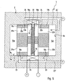
Figur 1 im Zustand des in der zweiten Endlage angelangten Oszillatorkolbens, und Figur 5- einen Ausschnitt einer weiteren Ausführungsform der Oszillatorvorrichtung im Längsschnitt und bei sich in der Übergangs-Bewegungsphase befindendem Oszillatorkolben.
- FIG. 1
- a longitudinal section through a preferred design of the oscillator device according to the invention, wherein the oscillator piston is in a first of its two end positions,
- FIG. 2
- 1 in the state of the oscillating piston moved out of the first end position when passing through the transition movement phase,
- FIG. 3
- 1 in a position of the oscillator piston, in which this has the transition movement phase behind him and is about to reach the second end position,
- FIG. 4
- the oscillator device of Figure 1 in the state of the arrested in the second end position oscillator piston, and
- FIG. 5
- a section of another embodiment of the oscillator device in longitudinal section and in the transition movement phase befindendem oscillator piston.
Die beiden zum einen in Figuren 1 bis 4 und zum anderen in Figur 5 gezeigten Ausführungsbeispiele einer pneumatischen Oszillatorvorrichtung 1 sind exemplarisch derart konstruktiv ausgebildet, dass sich mit ihrer Hilfe allein durch den Einsatz von Druckluft elektrische Energie erzeugen lässt. Andere Anwendungsfälle der Oszillatorvorrichtung 1 mit entsprechender konstruktiver Modifikation sind allerdings ebenfalls möglich, ohne das erfinderische Konzept zu verlassen.The two exemplary embodiments of a
Die Oszillatorvorrichtung 1 verfügt über ein Oszillatorgehäuse 2, in dem eine längliche, bevorzugt einen zylindrischen Querschnitt aufweisende Oszillationskammer 3 ausgebildet ist. Bevorzugt handelt es sich um eine kreiszylindrische Oszillationskammer 3, wenngleich auch längliche Querschnittsformen möglich wären, beispielsweise elliptischer Art oder mit geradlinigen Längsseiten und halbkreisförmigen Schmalseiten.The
In Figur 5 ist das Oszillatorgehäuse 2 nur schematisch angedeutet. Gemäß Figuren 1 bis 4 kann es sich aus mehreren Komponenten zusammensetzen, insbesondere einem die periphere Umfangsfläche 4 der Oszillationskammer 3 definierenden Rohrabschnitt 5 und zwei die axialen Abschlussflächen 6a, 6b der Oszillationskammer 3 definierenden Gehäusedeckeln 7a, 7b, wobei letztere unter Abdichtung fest mit dem Rohrabschnitt 5 verbunden sind. Zur Verbindung können Befestigungsschrauben 8 eingesetzt werden.In Figure 5, the
In der Oszillationskammer 3 befindet sich ein im Betrieb eine in Längsrichtung der Oszillationskammer 3 linear hin und her gehende Oszillationsbewegung 12 ausführender Oszillatorkolben 13. Er ist kürzer als die Oszillationskammer 3 und kann zwei einander entgegengesetzte axiale Endlagen einnehmen, wobei er zweckmäßigerweise in der ersten Endlage gemäß Figur 1 an der links liegenden ersten axialen Abschlussfläche 6a anliegt, während er in der zweiten Endlage gemäß Figur 4 an der rechts liegenden zweiten axialen Abschlussfläche 6b zur Anlage gelangt ist. Die die Endlagen definierenden Anschlagflächen können auch durch andere gehäusefeste Flächen vorgegeben werden, beispielsweise an bezüglich dem Gehäuse verstellbaren Anschlaggliedern.It is shorter than the
Die Definition der Endlagen durch gehäusefeste Anschlagflächen begünstigt ein konstantes Oszillationsverhalten und einen konstanten Hub des Oszillatorkolbens 13. Allerdings sind solche mechanischen Anschlagflächen nicht zwingend, weil auch ohne sie durch die sich einstellenden Druckverhältnisse eine automatische Umsteuerung der Bewegungsrichtung stattfindet. Auf diese Weise kann der Oszillatorkolben die Endlagen seiner Oszillationsbewegung erreichen und umgesteuert werden, bevor er an einer gehäusefesten Fläche zur Anlage gelangt.The definition of the end positions by housing-fixed stop surfaces favors a constant oscillation behavior and a constant stroke of the
Der Oszillatorkolben 13 teilt in der Oszillationskammer 3 zwei axial außenliegende erste bzw. zweite Arbeitskammern 14a, 14b voneinander ab, die bei der Oszillationsbewegung 12 ihre Volumina ändern, indem diese abwechselnd gegensinnig größer und kleiner werden.The
Bevorzugt hat der Oszillatorkolben 13 einen in mehrere fest miteinander verbundene Abschnitte unterteilten Aufbau. Axial mittig besitzt der Oszillatorkolben 13 einen Beaufschlagungsabschnitt 15, dessen Außenumfang komplementär zum Innenumfang der Oszillationskammer 3 ausgebildet ist und der verschiebbar an der Umfangsfläche 4 anliegt.Preferably, the
An den Beaufschlagungsabschnitt 15 schließt sich axial beidseits, unter Zwischenschaltung jeweils einer eine gewisse axiale Länge aufweisenden ersten bzw. zweiten Kolbenvertiefung 16a, 16b, ein erster bzw. zweiter Steuerabschnitt 17a, 17b an, der mit einer Steuerlänge "a" ebenfalls an der Umfangsfläche 4 gleitverschieblich anliegt. Die Außenkontur der Steuerabschnitte 17a, 17b entspricht der Querschnittskontur der Oszillationskammer 3.The
Die Kolbenvertiefungen 16a, 16b sind zweckmäßigerweise nach Art von Ringnuten ausgebildet, die sich entlang des gesamten Kolbenumfanges erstrecken, wobei sie zur Umfangsfläche 4 hin offen sind. Beim Ausführungsbeispiel ist die axiale Länge der Kolbenvertiefungen 16a, 16b kleiner als diejenige des Beaufschlagungsabschnittes 15 und der Steuerabschnitte 17a, 17b. Zweckmäßigerweise sind sie schlitzartig schmal ausgebildet.The piston recesses 16a, 16b are expediently designed in the manner of annular grooves which extend along the entire piston circumference, wherein they are open towards the circumferential surface 4. In the embodiment, the axial length of
An der Umfangsfläche 4 münden mit axialem Abstand zwei Abluftöffnungen ein, die als erste und zweite Abluftöffnung 18a, 18b bezeichnet seien und die im Betrieb der Oszillatorvorrichtung 1 ständig mit einer Drucksenke "R" verbunden sind. Bei dieser Drucksenke "R" handelt es sich insbesondere um die Atmosphäre in der unmittelbaren oder weiteren Umgebung der Oszillatorvorrichtung 1.On the peripheral surface 4 open at an axial distance two exhaust air openings, which are referred to as the first and
Des weiteren sind eine erste und eine zweite Zuluftöffnung 22a, 22b vorhanden, die beide in den axial zwischen den Einmündungen der beiden Abluftöffnungen 18a, 18b liegenden Bereich umfangsseitig in die Oszillationskammer 3 einmünden. Diese beiden Zuluftöffnungen 22a, 22b sind ihrerseits axial zueinander beabstandet, wobei die erste Zuluftöffnung 22a näher bei der ersten Abluftöffnung 18a und die zweite Zuluftöffnung 22b näher bei der zweiten Abluftöffnung 18b liegt. Die erste Abluftöffnung 18a ist der in der Zeichnung links liegenden ersten axialen Abschlussfläche 6a zugeordnet, während die zweite Abluftöffnung 18b in der Nähe der in der Zeichnung rechts liegenden zweiten axialen Abschlussfläche 6b liegt.Furthermore, a first and a second
Die Verteilung der Einmündungen der verschiedenen Öffnungen 18a, 18b, 22a, 22b entlang des Umfanges der Oszillationskammer 3 ist beim Ausführungsbeispiel, bei dem sowohl die Kolbenvertiefungen 16a, 16b als auch die Steuerabschnitte 17a, 17b sich jeweils entlang des gesamten Kolbenumfanges erstrecken, beliebig. Beim Ausführungsbeispiel liegen zum einen die Einmündungen der Abluftöffnungen 18a, 18b und zum anderen die Einmündungen der Zuluftöffnungen 22a, 22b untereinander auf einer sich axial erstreckenden Linie auf einander diametral gegenüberliegenden Seiten.The distribution of the junctions of the
Die beiden Zuluftöffnungen 22a, 22b sind im Betrieb der Oszillatorvorrichtung ständig an eine Druckluftquelle "P" angeschlossen.The two
Von den beiden Abluftöffnungen 18a, 18b geht jeweils ein Abluftkanal 23 ab, der die Wandung des Oszillatorgehäuses 2 durchsetzt und über den die Verbindung zur Drucksenke "R" hergestellt wird. In vergleichbarer Weise kommuniziert jede Zuluftöffnung 22a, 22b mit einem die Gehäusewandung durchsetzenden Zuluftkanal 24.From the two
Die Kanäle 23, 24 sind zweckmäßigerweise so ausgebildet, dass sich an ihnen, bevorzugt lösbar, Fluidleitungen anschließen lassen, die die Verbindung zur Druckluftquelle "P" bzw. Drucksenke "R" herstellen. Bei dem Ausführungsbeispiel der Figuren 1 bis 4 ist der äußere Mündungsbereich jedes Kanals 22, 23 mit einem Kupplungsstück 25 ausgestattet, in dem sich eine Fluidleitung beispielsweise ein elastischer Schlauch, lösbar unter Abdichtung fixieren lässt, beispielsweise im Rahmen einer Steckverbindung.The
Die Abluftkanäle 23 können am Außenumfang des Oszillatorgehäuses 2 frei enden, ohne Anschlussmöglichkeit für eine Fluidleitung, wenn eine direkte Verbindung zur unmittelbaren atmosphärischen Umgebung der Oszillatorvorrichtung 1 gewünscht ist.The
Bei dem Ausführungsbeispiel der Figuren 1 bis 4 sind alle vorhandenen Abluft- und Zuluftkanäle 23, 24 getrennt voreinander zur Außenseite des Oszillatorgehäuses 2 geführt, um separate Verbindungen zur Druckluftquelle "P" und Drucksenke "R" herzustellen. Aus Figur 5 wird jedoch deutlich, dass die gleichartigen Kanäle innerhalb der Gehäusewandung des Oszillatorgehäuses 2 auch zusammengeführt werden können, um über einen sich daran anschließenden gemeinsamen Anschlusskanal 23' bzw. 24' zur Außenfläche des Oszillatorgehäuses 2 geführt zu werden und dort einen gemeinsamen Anschluss zu ermöglichen.In the embodiment of Figures 1 to 4, all existing exhaust air and
Die Anordnung und Verteilung der Mündungen der Abluftöffnungen 18a, 18b und Zuluftöffnungen 22a, 22b sowie die Ausgestaltung des Oszillatorkolbens 13 sind so aufeinander abgestimmt, dass der Oszillatorkolben 13 in Bezug auf die Abluftöffnungen und Zuluftöffnungen ein Ventilglied bildet, das in Abhängigkeit von seiner momentanen Position eine bestimmte Verschaltung zwischen einerseits den Abluftöffnungen 18a, 18b und Zuluftöffnungen 22a, 22b und andererseits den beiden Arbeitskammern 14a, 14b hervorruft. Diese Verschaltung äußert sich darin, dass in den beiden Endlagen des Oszillatorkolbens 13 zwischen den beiden Arbeitskammern 14a, 14b einander entgegengesetzte Druckdifferenzen vorliegen.The arrangement and distribution of the mouths of the
Durch diese integrierte selbststeuernde Funktion wird erreicht, dass der Oszillatorkolben 13 die Oszillationsbewegung 12 ausführt und bei Erreichen der Endlagen selbst die Umsteuerung seiner Bewegungsrichtung hervorruft, wenn nur an den beiden Zuluftöffnungen 22a, 22b ein Überdruck und an den beiden Abluftöffnungen 18a, 18b ein diesbezüglich niedrigerer Druck, bevorzugt atmosphärischer Druck, anliegt.By this integrated self-controlling function ensures that the
Die Auslegung bei den Ausführungsbeispielen ist außerdem so getroffen, dass bei der Bewegung des Oszillatorkolbens 13 zwischen seinen beiden Endlagen eine Übergangs-Bewegungsphase auftritt, während der der Oszillatorkolben 13 sämtliche Zuluft- und Abluftöffnungen 18a, 18b; 22a; 22b von der Oszillationskammer 3 absperrt. Dadurch wird ein bei Bedarf relativ großer Oszillationshub begünstigt.The design in the embodiments is also made such that during the movement of the
In der aus Figur 1 ersichtlichen ersten Endlage liegt der Oszillatorkolben 13 an der ersten axialen Abschlussfläche 6a an, wobei die erste Abluftöffnung 18a durch den radial innen gegenüberliegenden ersten Steuerabschnitt 17a überdeckt und abgesperrt ist. Die erste Abluftöffnung 18a liegt dabei zweckmäßigerweise in der Nähe der ersten Kolbenvertiefung 16a, die ihrerseits mit der ersten Zuluftöffnung 22a verbunden ist, indem sie mit dieser radial fluchtet.In the first end position shown in FIG. 1, the
Die zweite Abluftöffnung 18b liegt in der ersten Endlage auf der dem Beaufschlagungsabschnitt 15 entgegengesetzten Axialseite des zweiten Steuerabschnittes 17b und wird von diesem nicht überdeckt, so dass sie mit der zweiten Arbeitskammer 14b verbunden ist. Die zweite Zuluftöffnung 22b wird gleichzeitig vom zweiten Steuerabschnitt 17b radial innen überdeckt und verschlossen. Dabei liegt die zweite Zuluftöffnung 22b in der Nähe des dem Beaufschlagungsabschnitt 15 entgegengesetzten Endbereiches des zweiten Steuerabschnittes 17b.The
Aufgrund eines oder mehrerer Ausgleichskanäle 26a, 26b, die den Oszillatorkolben 13 durchsetzen, wird erreicht, dass zwischen einer jeweiligen Kolbenvertiefung 16a, 16b und der auf der gleichen Seite des Beaufschlagungsabschnittes 15 liegenden Arbeitskammer 14a, 14b stets gleiche Druckverhältnisse herrschen. Bevorzugt ist der erste Steuerabschnitt 17a von mehreren ersten Ausgleichskanälen 26a und der zweite Steuerabschnitt 17b von mehreren zweiten Ausgleichskanälen 26b axial durchsetzt, wobei der radiale Abstand der Ausgleichskanäle 26a, 26b von der Längsachse 27 des Oszillatorkolbens 13 so gewählt ist, dass ihre dem Beaufschlagungsabschnitt 15 zugewandten Mündungen mit wenigstens einem Teil ihres Querschnittes auf die zugeordnete Kolbenvertiefung 16a, 16b treffen. Die entgegengesetzten Mündungen befinden sich an der axial äußeren Stirnfläche des jeweiligen Steuerabschnittes 17a, 17b.Due to one or
Die Ausgleichskanäle 26a, 26b sind beim Ausführungsbeispiel bohrungsartig ausgebildet. Möglich ist jedoch beispielsweise auch eine Gestaltung in Form sich axial erstreckender Oberflächenvertiefungen am Außenumfang des zugehörigen Steuerabschnittes, wie dies in Figur 5 bei 26c strichpunktiert exemplarisch angedeutet ist.The
Um bei Änderungen in den Druckverhältnissen einen raschen Druckausgleich über die Ausgleichskanäle 26a, 26b zu erzielen, sind beim Ausführungsbeispiel pro Steuerabschnitt 17a, 17b mehrere um die Längsachse 27 herum verteilte Ausgleichskanäle 26a, bzw. 26b vorgesehen, die jeweils eine Mehrzahl parallel geschalteter Fluidverbindungen hervorrufen.In order to achieve rapid pressure equalization via the
Bedingt durch die verschiedenen Ausgleichskanäle 26a, 26b wird erreicht, dass in der oben erwähnten ersten Endlage in der ersten Arbeitskammer 14a der gleiche Überdruck herrscht, wie in der mit der ersten Zuluftöffnung 22a kommunizierenden ersten Kolbenvertiefung 16a. Entsprechend herrscht in der zweiten Kolbenvertiefung 17b der gleiche niedrige Druck bzw. atmosphärische Druck wie in der mit der Abluftöffnung 18b kommunizierenden zweiten Arbeitskammer 14b.Due to the
Durch die Ausgleichskanäle 26a, 26b wird im übrigen auch erreicht, dass aus dem in der jeweils zugeordneten Arbeitskammer herrschenden momentanen Druck nur fluidische Stellkräfte resultieren, die axial in Richtung zur jeweils anderen Arbeitskammer gerichtet sind. In Figuren 1 und 2 sind in diesem Zusammenhang durch dickere Linien diejenigen Flächen auf der der ersten Arbeitskammer 14a zugeordneten Seite des Beaufschlagungsabschnittes 15 angedeutet, die für die Stellkraft FS1 verantwortlich sind, mit der der Oszillatorkolben 13 in Richtung der zweiten Endlage beaufschlagt wird.By the
In entsprechender Weise wirkt durch den in der zweiten Arbeitskammer 14b herrschenden Druck eine entgegengesetzt gerichtete Stellkraft FS2, wobei im Falle der Figuren 1 bis 4 die zur Stellkraft FS2, gehörende Beaufschlagungsfläche geringer ist, weil an dieser Axialseite eine die zweite Arbeitskammer 14b durchsetzende Stange 28 wegragt.In a corresponding manner acts by the pressure prevailing in the second working
In der ersten Endlage herrscht in der ersten Arbeitskammer 14a ein wesentlich höherer Druck als in der zweiten Arbeitskammer 14b, so dass die Stellkraft FS1 größer ist als die entgegengesetzt wirkende Stellkraft FS2 und der Oszillatorkolben 13 sich in Richtung der zweiten Endlage in Bewegung setzt. Bedingt durch die gewählte Steuerlänge "a" der beiden Steuerabschnitte 17a, 17b bleiben dabei zunächst die erste Abluftöffnung 18a und die zweite Zuluftöffnung 22b weiterhin verschlossen, während gleichzeitig die erste Zuluftöffnung 22a und die zweite Abluftöffnung 18b durch den sich darüber hinweg bewegenden Steuerabschnitt 17a bzw. 17b allmählich verschlossen werden.In the first end position prevails in the first working
Bei weitergehender Bewegung sind schließlich gemäß Figur 2 sämtliche Zuluft- und Abluftöffnungen durch die Steuerabschnitte 17a, 17b verschlossen. Da jedoch in der ersten Arbeitskammer 14a ein höherer Druck eingeschlossen ist als in der zweiten Arbeitskammer 14b, bewegt sich der Oszillatorkolben 13 unter Zurücklegung der schon erwähnten vorteilhaften Übergangs-Bewegungsphase trotzdem weiter.As the movement continues, finally, according to FIG. 2, all supply air and exhaust air openings are closed by the
An dieser Stelle sei angemerkt, dass Hinweise auf Drücke in den Arbeitskammern 14a, 14b als Hinweise auf den jeweiligen Volumenverbund bestehend aus zugeordneter Kolbenvertiefung und dazwischen verlaufenden Abluftöffnungen zu verstehen sind.It should be noted at this point that indications of pressures in the working
Nach Beendigung der Übergangs-Bewegungsphase bleiben gemäß Figur 3 die zweite Abluftöffnung 18b und die erste Zuluftöffnung 22a weiterhin abgesperrt, während die erste Abluftöffnung 18a mit der ersten Arbeitskammer 14a und die zweite Zuluftöffnung 22b mit der zweiten Kolbenvertiefung 16b und mithin der zweiten Arbeitskammer 14b in Verbindung tritt. Der Oszillatorkolben 13 hat dabei seine zweite Endlage noch nicht erreicht.According to FIG. 3, after the end of the transitional movement phase, the second
In dieser Phase findet eine Umkehr der auf den Oszillatorkolben 13 einwirkenden resultierenden Stellkraft statt, indem nun die Stellkraft FS2 größer ist als die ursprünglich größere Stellkraft FS1. Aufgrund der Massenträgheit bewegt sich der Oszillatorkolben 13 dennoch weiter, bis er zur Definition der aus Figur 4 hervorgehenden zweiten Endlage an der zweiten axialen Abschlussfläche 6b zur Anlage gelangt.In this phase, a reversal of the force acting on the
In dieser zweiten Endlage sind die erste Zuluftöffnung 22a und die zweite Abluftöffnung 18b weiterhin durch die Überdeckung seitens des zugeordneten Steuerabschnittes 17a, 17b abgesperrt, während gleichzeitig die zweite Zuluftöffnung 22b mit ihrem vollen Querschnitt mit der zweiten Kolbenvertiefung 16b und somit der zweiten Arbeitskammer 14b kommuniziert, während gleichzeitig die erste Abluftöffnung 18a mit ihrem vollen Querschnitt mit der ersten Arbeitskammer 14a verbunden ist.In this second end position, the first
Somit ergeben sich im Vergleich zur ersten Endlage im wesentlichen umgekehrte Kräfteverhältnisse, wobei sich lediglich aufgrund der Stange 28 eine minimal geringere resultierende Stellkraft ergibt, die sich aber auf das Bewegungsverhalten insgesamt nicht negativ auswirkt.Thus arise in comparison to the first end position substantially reversed balance of power, resulting in only due to the
Der in der zweiten Endlage gestoppte Oszillatorkolben 13 schließt unverzüglich die Rückbewegung in die erste Endlage gemäß Figur 1 an, wobei die geschilderten Bewegungsabläufe erneut auftreten, nun aber in entgegengesetzter Richtung.The stopped in the second end
Diese oszillierende Bewegung setzt sich ununterbrochen so lange fort, bis an den Zuluftöffnungen und Abluftöffnungen ein gleich hoher Druck angelegt wird, was zweckmäßigerweise dadurch geschieht, dass man die Druckluftquelle von den beiden Zuluftöffnungen 22a, 22b abtrennt.This oscillating movement continues uninterrupted until an equal high pressure is applied to the supply air openings and exhaust air openings, which is expediently achieved by separating the compressed air source from the two
Um zu verhindern, dass der Oszillatorkolben beim ersten Loslaufen in einer Mittelstellung verharrt, ist eine der Arbeitskammern 14b zweckmäßigerweise ständig über eine Drosselstelle 32 mit einer Druckluftquelle verbunden. Durch diese bevorzugt als Bohrung mit sehr kleinem Querschnitt ausgebildete Drosselstelle erreicht man eine leichte Asymmetrie bei den Kräfteverhältnissen, die zur Folge hat, dass der Oszillatorkolben am Betriebsbeginn in eine Endstellung gezwungen wird, von der aus dann die Oszillationsbewegung starten kann.In order to prevent the oscillator piston from remaining in a middle position during the first start, one of the working
Die zur Versorgung der Drosselstelle 32 verwendete Druckluftquelle stimmt zweckmäßigerweise mit derjenigen überein, an die die Zuluftöffnungen 22a, 22b angeschlossen sind. Gemäß Figur 5 kann die Drosselstelle 32 in der Gehäusewandung an den gemeinsamen Kanal 24' angeschlossen sein. Gemäß Figuren 1 bis 4 besteht allerdings auch die Möglichkeit, den der Drosselstellung 32 zugeordneten Drosselkanal 32' separat zur Außenfläche des Oszillatorgehäuses zu führen, wo ein weiteres Kupplungsstück 25' vorgesehen sein kann, über das eine zur Druckluftquelle führende Fluidleitung lösbar angeschlossen werden kann.The compressed air source used to supply the
Um sehr hohe Oszillationsfrequenzen zu erzielen, ist der Oszillatorkolben 13 zweckmäßigerweise dichtungslos gleitend in der Oszillationskammer 3 angeordnet. Durch exakte Bearbeitung kann auch ohne elastomere Dichtungsmittel die für den Betrieb notwendige Ventilfunktion mit Absperren und Freigeben der Zuluft- und Abluftöffnungen garantiert werden.In order to achieve very high oscillation frequencies, the
Es hat sich gezeigt, dass im Betrieb der Oszillatorvorrichtung ohne weiteres eine Oszillationsfrequenz von 180 Hertz erreichbar ist.It has been found that during operation of the oscillator device, an oscillation frequency of 180 hertz can be achieved without further ado.
Bei den gezeigten Ausführungsbeispielen wird der Oszillatorkolben 13 als Antriebsglied für einen Bewegungsabgriff herangezogen. Genauer gesagt dient der Oszillatorkolben 13 der Erzeugung einer durch einen Doppelpfeil angedeuteten oszillierenden Hubbewegung 33 eines Permanentmagneten 34 relativ zu einer bezüglich dem Oszillatorgehäuse 2 ortsfesten Spulenanordnung 35.In the embodiments shown, the
Bei dem Ausführungsbeispiel der Figuren 1 bis 4 fungiert die schon erwähnte Stange 28 als Träger für den mindestens einen Permanentmagnet 34. Die bevorzugt einstückig mit dem Oszillatorkolben 13 ausgebildete Stange 28 durchsetzt die eine Arbeitskammer 14b und den diese abschließenden Deckel 7b in axial beweglicher Weise und ist außerhalb der Oszillationskammer 3 mit dem Permanentmagnet 34 bestückt. Die Spulenanordnung 35 ist koaxial zur Längsachse 27 des Oszillatorkolbens 13 angeordnet und über eine Halterung 36 am Oszillatorgehäuse 2 befestigt. Bei der durch die Oszillationsbewegung 12 hervorgerufenen oszillierenden Hubbewegung 33 bewegt sich der Permanentmagnet 34 fortwährend in einander entgegengesetzten Richtungen durch die Spulenanordnung 35 hindurch, in der mithin eine elektrische Spannung induziert wird, welche sich für den Betrieb elektrischer und/oder elektronischer Mittel abgreifen lässt.In the embodiment of Figures 1 to 4, the already mentioned
Während beim Ausführungsbeispiel der Figuren 1 bis 4 die Spulenanordnung 35 in koaxialer Verlängerung der Oszillationskammer 3 außerhalb derselben angeordnet ist, befindet sich die Spulenanordnung 35 beim Ausführungsbeispiel der Figur 5 in einer die Oszillationskammer 3 koaxial umschließenden Konstellation.While in the embodiment of Figures 1 to 4, the
Der für die magnetische Induktion zuständige mindestens eine Permanentmagnet 34 sitzt in diesem Falle unmittelbar am Oszillatorkolben 13 innerhalb der Oszillationskammer 3, so dass sich ein Herausführen von mit dem Oszillatorkolben 13 bewegungsgekoppelten Betätigungselementen aus der Oszillationskammer 3 erübrigt. Somit entfällt die beim anderen Ausführungsbeispiel im Durchdringungsbereich der Stange 28 angeordnete Dichtstelle und man erreicht insgesamt eine axial sehr kompakt bauende Anordnung.The responsible for the magnetic induction at least one
Für die Abdichtung des Durchdringungsbereiches der Stange 28 am Gehäusedeckel 7b kann bei Einhaltung minimaler Spaltbreiten zugunsten einer reibungsarmen Bewegung ebenfalls auf spezielle Dichtungsmittel verzichtet werden.For the sealing of the penetration area of the
Sollen am Oszillatorkolben 13 bei beiden Bewegungsrichtungen übereinstimmende Stellkräfte erzeugt werden, kann anstelle der aus Figur 5 ersichtlichen stangenlosen Ausführungsform auch eine Modifikation der Bauform gemäß Figuren 1 bis 4 dahingehend vorgenommen werden, dass man auf der der Stange 28 entgegengesetzten Axialseite eine Stange 28' gleichen Querschnittes durch den dortigen Gehäusedeckel 7a hindurch herausführt, die ebenfalls mit dem Oszillatorkolben 13 verbunden ist. Bei Bedarf kann an dieser weiteren Stange 28' ebenfalls ein Bewegungsabgriff erfolgen, beispielsweise um einen mit einer zweiten Spulenanordnung kooperierenden weiteren Permanentmagnet anzutreiben.If identical actuating forces are to be generated on the
Claims (17)
dadurch gekennzeichnet,
characterized,
Priority Applications (3)
| Application Number | Priority Date | Filing Date | Title |
|---|---|---|---|
| DK04026664T DK1657452T3 (en) | 2004-11-10 | 2004-11-10 | Pneumatic oscillator device |
| DE200450005715 DE502004005715D1 (en) | 2004-11-10 | 2004-11-10 | Pneumatic oscillator device |
| EP04026664A EP1657452B1 (en) | 2004-11-10 | 2004-11-10 | Pneumatic oscillator |
Applications Claiming Priority (1)
| Application Number | Priority Date | Filing Date | Title |
|---|---|---|---|
| EP04026664A EP1657452B1 (en) | 2004-11-10 | 2004-11-10 | Pneumatic oscillator |
Publications (2)
| Publication Number | Publication Date |
|---|---|
| EP1657452A1 true EP1657452A1 (en) | 2006-05-17 |
| EP1657452B1 EP1657452B1 (en) | 2007-12-12 |
Family
ID=34927316
Family Applications (1)
| Application Number | Title | Priority Date | Filing Date |
|---|---|---|---|
| EP04026664A Expired - Fee Related EP1657452B1 (en) | 2004-11-10 | 2004-11-10 | Pneumatic oscillator |
Country Status (3)
| Country | Link |
|---|---|
| EP (1) | EP1657452B1 (en) |
| DE (1) | DE502004005715D1 (en) |
| DK (1) | DK1657452T3 (en) |
Cited By (4)
| Publication number | Priority date | Publication date | Assignee | Title |
|---|---|---|---|---|
| WO2011056855A1 (en) * | 2009-11-03 | 2011-05-12 | Sustainx, Inc. | Systems and methods for compressed-gas energy storage using coupled cylinder assemblies |
| CN107014583A (en) * | 2017-05-08 | 2017-08-04 | 大连理工大学 | A kind of multi-functional both ends open pressure oscillation pipe test platform |
| CN107917928A (en) * | 2017-11-01 | 2018-04-17 | 大连理工大学 | A kind of dual openings multitubular bundles refrigeration machine Unsteady Heat Transfer test platform |
| CN109114067A (en) * | 2018-09-21 | 2019-01-01 | 仁兴机械(佛山)有限公司 | A kind of cylinder, cylinder structure |
Families Citing this family (21)
| Publication number | Priority date | Publication date | Assignee | Title |
|---|---|---|---|---|
| US20100307156A1 (en) | 2009-06-04 | 2010-12-09 | Bollinger Benjamin R | Systems and Methods for Improving Drivetrain Efficiency for Compressed Gas Energy Storage and Recovery Systems |
| US8359856B2 (en) | 2008-04-09 | 2013-01-29 | Sustainx Inc. | Systems and methods for efficient pumping of high-pressure fluids for energy storage and recovery |
| US8448433B2 (en) | 2008-04-09 | 2013-05-28 | Sustainx, Inc. | Systems and methods for energy storage and recovery using gas expansion and compression |
| US8037678B2 (en) | 2009-09-11 | 2011-10-18 | Sustainx, Inc. | Energy storage and generation systems and methods using coupled cylinder assemblies |
| US8677744B2 (en) | 2008-04-09 | 2014-03-25 | SustaioX, Inc. | Fluid circulation in energy storage and recovery systems |
| US8474255B2 (en) | 2008-04-09 | 2013-07-02 | Sustainx, Inc. | Forming liquid sprays in compressed-gas energy storage systems for effective heat exchange |
| US8240140B2 (en) | 2008-04-09 | 2012-08-14 | Sustainx, Inc. | High-efficiency energy-conversion based on fluid expansion and compression |
| US7958731B2 (en) | 2009-01-20 | 2011-06-14 | Sustainx, Inc. | Systems and methods for combined thermal and compressed gas energy conversion systems |
| US8479505B2 (en) | 2008-04-09 | 2013-07-09 | Sustainx, Inc. | Systems and methods for reducing dead volume in compressed-gas energy storage systems |
| EP2280841A2 (en) | 2008-04-09 | 2011-02-09 | Sustainx, Inc. | Systems and methods for energy storage and recovery using compressed gas |
| US8250863B2 (en) | 2008-04-09 | 2012-08-28 | Sustainx, Inc. | Heat exchange with compressed gas in energy-storage systems |
| US8225606B2 (en) | 2008-04-09 | 2012-07-24 | Sustainx, Inc. | Systems and methods for energy storage and recovery using rapid isothermal gas expansion and compression |
| US7802426B2 (en) | 2008-06-09 | 2010-09-28 | Sustainx, Inc. | System and method for rapid isothermal gas expansion and compression for energy storage |
| US8104274B2 (en) | 2009-06-04 | 2012-01-31 | Sustainx, Inc. | Increased power in compressed-gas energy storage and recovery |
| US8191362B2 (en) | 2010-04-08 | 2012-06-05 | Sustainx, Inc. | Systems and methods for reducing dead volume in compressed-gas energy storage systems |
| US8171728B2 (en) | 2010-04-08 | 2012-05-08 | Sustainx, Inc. | High-efficiency liquid heat exchange in compressed-gas energy storage systems |
| US8234863B2 (en) | 2010-05-14 | 2012-08-07 | Sustainx, Inc. | Forming liquid sprays in compressed-gas energy storage systems for effective heat exchange |
| US8495872B2 (en) | 2010-08-20 | 2013-07-30 | Sustainx, Inc. | Energy storage and recovery utilizing low-pressure thermal conditioning for heat exchange with high-pressure gas |
| US8578708B2 (en) | 2010-11-30 | 2013-11-12 | Sustainx, Inc. | Fluid-flow control in energy storage and recovery systems |
| JP2014522460A (en) | 2011-05-17 | 2014-09-04 | サステインエックス, インコーポレイテッド | System and method for efficient two-phase heat transfer in a compressed air energy storage system |
| US20130091836A1 (en) | 2011-10-14 | 2013-04-18 | Sustainx, Inc. | Dead-volume management in compressed-gas energy storage and recovery systems |
Citations (7)
| Publication number | Priority date | Publication date | Assignee | Title |
|---|---|---|---|---|
| US385113A (en) * | 1888-06-26 | of kupfebhammee | ||
| US835290A (en) * | 1905-12-07 | 1906-11-06 | Clarence H Richwood | Fluid-actuated vibrator. |
| US2763060A (en) * | 1952-07-28 | 1956-09-18 | Bernard A Swanson | Fluid pressure operated reciprocatory vibratory sheet material cutting shears |
| CH337157A (en) * | 1954-12-18 | 1959-03-15 | Mohr Rudolf Dr | Compressed air tool |
| US5195560A (en) * | 1992-04-27 | 1993-03-23 | Muchlis Achmad | Adjustable low frequency hydrofluidic oscillator |
| DE19636207A1 (en) * | 1996-09-06 | 1998-03-12 | Samson Ag | Electrical-fluidic signals converter |
| EP1071195A2 (en) * | 1999-07-21 | 2001-01-24 | Westinghouse Air Brake Company | High efficiency pneumatically driven electric power generator |
-
2004
- 2004-11-10 DK DK04026664T patent/DK1657452T3/en active
- 2004-11-10 DE DE200450005715 patent/DE502004005715D1/en active Active
- 2004-11-10 EP EP04026664A patent/EP1657452B1/en not_active Expired - Fee Related
Patent Citations (9)
| Publication number | Priority date | Publication date | Assignee | Title |
|---|---|---|---|---|
| US385113A (en) * | 1888-06-26 | of kupfebhammee | ||
| US835290A (en) * | 1905-12-07 | 1906-11-06 | Clarence H Richwood | Fluid-actuated vibrator. |
| US2763060A (en) * | 1952-07-28 | 1956-09-18 | Bernard A Swanson | Fluid pressure operated reciprocatory vibratory sheet material cutting shears |
| CH337157A (en) * | 1954-12-18 | 1959-03-15 | Mohr Rudolf Dr | Compressed air tool |
| US5195560A (en) * | 1992-04-27 | 1993-03-23 | Muchlis Achmad | Adjustable low frequency hydrofluidic oscillator |
| EP0638145B1 (en) | 1992-04-27 | 1997-02-26 | Hr Textron Inc. | Adjustable low frequency hydrofluidic oscillator |
| DE19636207A1 (en) * | 1996-09-06 | 1998-03-12 | Samson Ag | Electrical-fluidic signals converter |
| DE19636207C2 (en) | 1996-09-06 | 2000-08-03 | Samson Ag | Electric-fluid converter |
| EP1071195A2 (en) * | 1999-07-21 | 2001-01-24 | Westinghouse Air Brake Company | High efficiency pneumatically driven electric power generator |
Cited By (6)
| Publication number | Priority date | Publication date | Assignee | Title |
|---|---|---|---|---|
| WO2011056855A1 (en) * | 2009-11-03 | 2011-05-12 | Sustainx, Inc. | Systems and methods for compressed-gas energy storage using coupled cylinder assemblies |
| CN107014583A (en) * | 2017-05-08 | 2017-08-04 | 大连理工大学 | A kind of multi-functional both ends open pressure oscillation pipe test platform |
| CN107014583B (en) * | 2017-05-08 | 2023-07-04 | 大连理工大学 | Multifunctional pressure oscillation tube testing platform with two openings at two ends |
| CN107917928A (en) * | 2017-11-01 | 2018-04-17 | 大连理工大学 | A kind of dual openings multitubular bundles refrigeration machine Unsteady Heat Transfer test platform |
| CN107917928B (en) * | 2017-11-01 | 2024-02-02 | 大连理工大学 | Unsteady heat conduction test platform of double-opening multi-tube-bundle refrigerator |
| CN109114067A (en) * | 2018-09-21 | 2019-01-01 | 仁兴机械(佛山)有限公司 | A kind of cylinder, cylinder structure |
Also Published As
| Publication number | Publication date |
|---|---|
| DE502004005715D1 (en) | 2008-01-24 |
| EP1657452B1 (en) | 2007-12-12 |
| DK1657452T3 (en) | 2008-01-07 |
Similar Documents
| Publication | Publication Date | Title |
|---|---|---|
| EP1657452B1 (en) | Pneumatic oscillator | |
| EP0279177B1 (en) | Valve with a controlled leakage space | |
| DE3323363C2 (en) | ||
| EP2397732B1 (en) | Device for operating a double seat valve | |
| DE102010010061A1 (en) | Multi-way valve | |
| EP3067598B1 (en) | Multi-port valve | |
| EP3087279B1 (en) | Valve assembly | |
| EP0081703A1 (en) | Electro-hydraulic actuator | |
| DE19732761A1 (en) | Ram-piston damping system at end positions | |
| EP0085298B1 (en) | Multiple-way valve, especially for use in dialyzers | |
| DE4027610C2 (en) | Valve | |
| DE19652707C2 (en) | Pneumatic knocker | |
| EP0687818B1 (en) | Pneumatic valve | |
| EP0669469A1 (en) | Fluid driven rotary actuator | |
| EP0620932B1 (en) | Electro-hydraulic control device and pressure reducing valve | |
| DE4011908A1 (en) | Multi-way control valve - has double action servo cylinder at end of valve element | |
| DE4326447A1 (en) | Hydraulic valve for a stabiliser control on a motor vehicle | |
| EP3412944A1 (en) | Control valve | |
| DE4119402C2 (en) | Slide valve | |
| DE3315056C2 (en) | Electro-hydraulic multi-way control valve | |
| EP0060412B1 (en) | End-of-stroke cushioning device for a piston of a double-acting cylinder | |
| EP4027042A1 (en) | Motor vehicle directional control valve for adjusting a fluid flow | |
| EP1042615B1 (en) | Fluid-actuated working device | |
| DE102004046976B4 (en) | Multi-way valve | |
| DE19757157C2 (en) | Hydraulic linear drive |
Legal Events
| Date | Code | Title | Description |
|---|---|---|---|
| PUAI | Public reference made under article 153(3) epc to a published international application that has entered the european phase |
Free format text: ORIGINAL CODE: 0009012 |
|
| 17P | Request for examination filed |
Effective date: 20050702 |
|
| AK | Designated contracting states |
Kind code of ref document: A1 Designated state(s): AT BE BG CH CY CZ DE DK EE ES FI FR GB GR HU IE IS IT LI LU MC NL PL PT RO SE SI SK TR |
|
| AX | Request for extension of the european patent |
Extension state: AL HR LT LV MK YU |
|
| GRAP | Despatch of communication of intention to grant a patent |
Free format text: ORIGINAL CODE: EPIDOSNIGR1 |
|
| AKX | Designation fees paid |
Designated state(s): DE DK FR GB IT |
|
| GRAS | Grant fee paid |
Free format text: ORIGINAL CODE: EPIDOSNIGR3 |
|
| GRAA | (expected) grant |
Free format text: ORIGINAL CODE: 0009210 |
|
| AK | Designated contracting states |
Kind code of ref document: B1 Designated state(s): DE DK FR GB IT |
|
| REG | Reference to a national code |
Ref country code: GB Ref legal event code: FG4D Free format text: NOT ENGLISH |
|
| GBT | Gb: translation of ep patent filed (gb section 77(6)(a)/1977) |
Effective date: 20071212 |
|
| REG | Reference to a national code |
Ref country code: DK Ref legal event code: T3 |
|
| REF | Corresponds to: |
Ref document number: 502004005715 Country of ref document: DE Date of ref document: 20080124 Kind code of ref document: P |
|
| ET | Fr: translation filed | ||
| PLBE | No opposition filed within time limit |
Free format text: ORIGINAL CODE: 0009261 |
|
| STAA | Information on the status of an ep patent application or granted ep patent |
Free format text: STATUS: NO OPPOSITION FILED WITHIN TIME LIMIT |
|
| 26N | No opposition filed |
Effective date: 20080915 |
|
| PGFP | Annual fee paid to national office [announced via postgrant information from national office to epo] |
Ref country code: DE Payment date: 20111206 Year of fee payment: 8 |
|
| PGFP | Annual fee paid to national office [announced via postgrant information from national office to epo] |
Ref country code: DK Payment date: 20121126 Year of fee payment: 9 |
|
| PGFP | Annual fee paid to national office [announced via postgrant information from national office to epo] |
Ref country code: IT Payment date: 20121122 Year of fee payment: 9 Ref country code: GB Payment date: 20121019 Year of fee payment: 9 |
|
| PGFP | Annual fee paid to national office [announced via postgrant information from national office to epo] |
Ref country code: FR Payment date: 20121217 Year of fee payment: 9 |
|
| REG | Reference to a national code |
Ref country code: DE Ref legal event code: R119 Ref document number: 502004005715 Country of ref document: DE Effective date: 20130601 |
|
| PG25 | Lapsed in a contracting state [announced via postgrant information from national office to epo] |
Ref country code: DE Free format text: LAPSE BECAUSE OF NON-PAYMENT OF DUE FEES Effective date: 20130601 |
|
| REG | Reference to a national code |
Ref country code: DK Ref legal event code: EBP Effective date: 20131130 |
|
| GBPC | Gb: european patent ceased through non-payment of renewal fee |
Effective date: 20131110 |
|
| REG | Reference to a national code |
Ref country code: FR Ref legal event code: ST Effective date: 20140731 |
|
| PG25 | Lapsed in a contracting state [announced via postgrant information from national office to epo] |
Ref country code: IT Free format text: LAPSE BECAUSE OF NON-PAYMENT OF DUE FEES Effective date: 20131110 |
|
| PG25 | Lapsed in a contracting state [announced via postgrant information from national office to epo] |
Ref country code: DK Free format text: LAPSE BECAUSE OF NON-PAYMENT OF DUE FEES Effective date: 20131130 |
|
| PG25 | Lapsed in a contracting state [announced via postgrant information from national office to epo] |
Ref country code: GB Free format text: LAPSE BECAUSE OF NON-PAYMENT OF DUE FEES Effective date: 20131110 Ref country code: FR Free format text: LAPSE BECAUSE OF NON-PAYMENT OF DUE FEES Effective date: 20131202 |