EP1657434A1 - A high-pressure pump with a device for regulating the flow rate for a fuel-injection system - Google Patents
A high-pressure pump with a device for regulating the flow rate for a fuel-injection system Download PDFInfo
- Publication number
- EP1657434A1 EP1657434A1 EP04425840A EP04425840A EP1657434A1 EP 1657434 A1 EP1657434 A1 EP 1657434A1 EP 04425840 A EP04425840 A EP 04425840A EP 04425840 A EP04425840 A EP 04425840A EP 1657434 A1 EP1657434 A1 EP 1657434A1
- Authority
- EP
- European Patent Office
- Prior art keywords
- pressure pump
- fuel
- solenoid valve
- suction
- pumping
- Prior art date
- Legal status (The legal status is an assumption and is not a legal conclusion. Google has not performed a legal analysis and makes no representation as to the accuracy of the status listed.)
- Granted
Links
Images



Classifications
-
- F—MECHANICAL ENGINEERING; LIGHTING; HEATING; WEAPONS; BLASTING
- F02—COMBUSTION ENGINES; HOT-GAS OR COMBUSTION-PRODUCT ENGINE PLANTS
- F02M—SUPPLYING COMBUSTION ENGINES IN GENERAL WITH COMBUSTIBLE MIXTURES OR CONSTITUENTS THEREOF
- F02M59/00—Pumps specially adapted for fuel-injection and not provided for in groups F02M39/00 -F02M57/00, e.g. rotary cylinder-block type of pumps
- F02M59/02—Pumps specially adapted for fuel-injection and not provided for in groups F02M39/00 -F02M57/00, e.g. rotary cylinder-block type of pumps of reciprocating-piston or reciprocating-cylinder type
- F02M59/04—Pumps specially adapted for fuel-injection and not provided for in groups F02M39/00 -F02M57/00, e.g. rotary cylinder-block type of pumps of reciprocating-piston or reciprocating-cylinder type characterised by special arrangement of cylinders with respect to piston-driving shaft, e.g. arranged parallel to that shaft or swash-plate type pumps
- F02M59/06—Pumps specially adapted for fuel-injection and not provided for in groups F02M39/00 -F02M57/00, e.g. rotary cylinder-block type of pumps of reciprocating-piston or reciprocating-cylinder type characterised by special arrangement of cylinders with respect to piston-driving shaft, e.g. arranged parallel to that shaft or swash-plate type pumps with cylinders arranged radially to driving shaft, e.g. in V or star arrangement
-
- F—MECHANICAL ENGINEERING; LIGHTING; HEATING; WEAPONS; BLASTING
- F02—COMBUSTION ENGINES; HOT-GAS OR COMBUSTION-PRODUCT ENGINE PLANTS
- F02D—CONTROLLING COMBUSTION ENGINES
- F02D41/00—Electrical control of supply of combustible mixture or its constituents
- F02D41/30—Controlling fuel injection
- F02D41/38—Controlling fuel injection of the high pressure type
- F02D41/3809—Common rail control systems
- F02D41/3836—Controlling the fuel pressure
- F02D41/3845—Controlling the fuel pressure by controlling the flow into the common rail, e.g. the amount of fuel pumped
-
- F—MECHANICAL ENGINEERING; LIGHTING; HEATING; WEAPONS; BLASTING
- F02—COMBUSTION ENGINES; HOT-GAS OR COMBUSTION-PRODUCT ENGINE PLANTS
- F02D—CONTROLLING COMBUSTION ENGINES
- F02D41/00—Electrical control of supply of combustible mixture or its constituents
- F02D41/30—Controlling fuel injection
- F02D41/38—Controlling fuel injection of the high pressure type
- F02D41/40—Controlling fuel injection of the high pressure type with means for controlling injection timing or duration
- F02D41/406—Electrically controlling a diesel injection pump
-
- F—MECHANICAL ENGINEERING; LIGHTING; HEATING; WEAPONS; BLASTING
- F02—COMBUSTION ENGINES; HOT-GAS OR COMBUSTION-PRODUCT ENGINE PLANTS
- F02M—SUPPLYING COMBUSTION ENGINES IN GENERAL WITH COMBUSTIBLE MIXTURES OR CONSTITUENTS THEREOF
- F02M59/00—Pumps specially adapted for fuel-injection and not provided for in groups F02M39/00 -F02M57/00, e.g. rotary cylinder-block type of pumps
- F02M59/02—Pumps specially adapted for fuel-injection and not provided for in groups F02M39/00 -F02M57/00, e.g. rotary cylinder-block type of pumps of reciprocating-piston or reciprocating-cylinder type
- F02M59/10—Pumps specially adapted for fuel-injection and not provided for in groups F02M39/00 -F02M57/00, e.g. rotary cylinder-block type of pumps of reciprocating-piston or reciprocating-cylinder type characterised by the piston-drive
- F02M59/102—Mechanical drive, e.g. tappets or cams
-
- F—MECHANICAL ENGINEERING; LIGHTING; HEATING; WEAPONS; BLASTING
- F02—COMBUSTION ENGINES; HOT-GAS OR COMBUSTION-PRODUCT ENGINE PLANTS
- F02M—SUPPLYING COMBUSTION ENGINES IN GENERAL WITH COMBUSTIBLE MIXTURES OR CONSTITUENTS THEREOF
- F02M59/00—Pumps specially adapted for fuel-injection and not provided for in groups F02M39/00 -F02M57/00, e.g. rotary cylinder-block type of pumps
- F02M59/20—Varying fuel delivery in quantity or timing
- F02M59/36—Varying fuel delivery in quantity or timing by variably-timed valves controlling fuel passages to pumping elements or overflow passages
- F02M59/366—Valves being actuated electrically
-
- F—MECHANICAL ENGINEERING; LIGHTING; HEATING; WEAPONS; BLASTING
- F02—COMBUSTION ENGINES; HOT-GAS OR COMBUSTION-PRODUCT ENGINE PLANTS
- F02M—SUPPLYING COMBUSTION ENGINES IN GENERAL WITH COMBUSTIBLE MIXTURES OR CONSTITUENTS THEREOF
- F02M63/00—Other fuel-injection apparatus having pertinent characteristics not provided for in groups F02M39/00 - F02M57/00 or F02M67/00; Details, component parts, or accessories of fuel-injection apparatus, not provided for in, or of interest apart from, the apparatus of groups F02M39/00 - F02M61/00 or F02M67/00; Combination of fuel pump with other devices, e.g. lubricating oil pump
- F02M63/02—Fuel-injection apparatus having several injectors fed by a common pumping element, or having several pumping elements feeding a common injector; Fuel-injection apparatus having provisions for cutting-out pumps, pumping elements, or injectors; Fuel-injection apparatus having provisions for variably interconnecting pumping elements and injectors alternatively
- F02M63/0225—Fuel-injection apparatus having a common rail feeding several injectors ; Means for varying pressure in common rails; Pumps feeding common rails
-
- Y—GENERAL TAGGING OF NEW TECHNOLOGICAL DEVELOPMENTS; GENERAL TAGGING OF CROSS-SECTIONAL TECHNOLOGIES SPANNING OVER SEVERAL SECTIONS OF THE IPC; TECHNICAL SUBJECTS COVERED BY FORMER USPC CROSS-REFERENCE ART COLLECTIONS [XRACs] AND DIGESTS
- Y02—TECHNOLOGIES OR APPLICATIONS FOR MITIGATION OR ADAPTATION AGAINST CLIMATE CHANGE
- Y02T—CLIMATE CHANGE MITIGATION TECHNOLOGIES RELATED TO TRANSPORTATION
- Y02T10/00—Road transport of goods or passengers
- Y02T10/10—Internal combustion engine [ICE] based vehicles
- Y02T10/40—Engine management systems
Definitions
- the present invention relates to a high-pressure pump with a device for regulating the flow rate for a fuel injection system of an internal combustion engine.
- the high-pressure pump is designed to send fuel to a common rail having a pre-set accumulation volume of pressurized fuel, for supplying a plurality of injectors associated to the cylinders of the engine.
- a common rail having a pre-set accumulation volume of pressurized fuel, for supplying a plurality of injectors associated to the cylinders of the engine.
- This must be brought to a very high pressure, in the region of 1600 bar in the conditions of maximum power of the engine.
- the pressure of the fuel required in the common rail is in general defined by an electronic control unit as a function of the operating conditions, i.e., the running conditions of the engine.
- Injection systems are known in which a by-pass solenoid valve, arranged on the delivery pipe of the pump, is controlled by the control unit for draining off directly the excess fuel just pumped into the usual fuel tank, before said fuel enters the common rail.
- the flow rate of the high-pressure pump in general depends upon the speed of rotation of the engine crankshaft, it must be sized so as to achieve the maximum flow-rate and pressure values required by the various operating conditions of the engine. In certain operating conditions, for example at the maximum speed but with low power of the engine shaft, the flow rate of the pump proves overabundant, and the fuel in excess is simply drained off into the tank. Consequently, these known regulation devices present the drawback of dissipating part of the work of compression of the high-pressure pump in the form of heat.
- Variable-flow-rate high-pressure pumps have been proposed to reduce the amount of fuel pumped when the engine functions at low power.
- the intake pipe is provided with a flow-rate regulation device comprising a restriction with a cross section that varies with continuity, which is controlled by the electronic-control unit as a function of the pressure required in the common rail and/or as a function of the operating conditions of the engine.
- the restriction in the intake pipe is supplied with a constant pressure difference ⁇ P of approximately 5 bar, supplied by an auxiliary pump.
- ⁇ P constant pressure difference
- said spring must be calibrated in a very precise way, so that the pump proves relatively costly, and, on the other hand, there is always the risk that the intake valve will be unable to open on account of the negative pressure caused by the pumping element in the corresponding compression chamber, so that the pump does not function correctly and is highly subject to deterioration.
- the purpose of the invention is to provide a high-pressure fuel pump with a flow-rate regulation device which is of high reliability and of contained cost and will enable the drawbacks of fuel pumps of the known art to be overcome.
- a high-pressure pump with a flow-rate regulation device for a fuel-injection system of an internal combustion engine comprising a number of pumping elements, which are actuated with reciprocating motion through corresponding suction and delivery strokes, each of said pumping elements being provided with a corresponding intake valve in communication with an intake pipe, and with a corresponding delivery valve in communication with an accumulation volume of pressurized fuel, said pump being characterized in that said regulation device comprises at least one solenoid valve for shut off of the fuel supplied to said pumping elements, said solenoid valve being set on said intake pipe and being actuated during the suction strokes of said pumping elements so that opening of said solenoid valve will take place with a certain delay with respect to the start of the suction strokes themselves.
- the shut-off solenoid valve has a cross section such as to enable it to supply each pumping element only with the fuel required in the corresponding suction stroke, and is designed to be controlled in a chopped way by a control unit, which controls opening thereof during an intermediate part of each suction stroke of said pumping elements.
- number 1 designates, as a whole, a fuel-injection system for an internal-combustion engine 2, for example a four-stroke diesel engine.
- the engine 2 comprises a plurality of cylinders 3, for example four cylinders, which co-operate with corresponding pistons (not shown), which can be actuated for rotating an engine shaft 4.
- the injection system 1 comprises a plurality of electromagnetically controlled injectors 5, associated to the cylinders 3 and designed to inject therein the fuel at a high pressure.
- the injectors 5 are connected to an accumulation volume, which has a pre-set volume for one or more injectors 5.
- the accumulation volume is formed by the usual common rail 6, connected to which are all the injectors 5.
- the common rail 6 is supplied with fuel at a high pressure by a high-pressure pump, as a whole designated by 7, via a delivery pipe 8.
- the high-pressure pump 7 is supplied by a low-pressure pump, for example an electric pump 9, via an intake pipe 10 of the pump 7.
- the electric pump 9 is in general arranged in the usual fuel tank 11, into which there gives out a discharge pipe 12 for draining off the excess fuel of the injection system 1.
- the common rail 6 is moreover provided with a drain solenoid valve 15 in communication with the discharge pipe 12.
- Each injector 5 is designed to inject, into the corresponding cylinder 3, an amount of fuel that varies between a minimum value and a maximum value, under the control of an electronic control unit 16, which can consist of the usual microprocessor control unit of the engine 2.
- the control unit 16 is designed to receive signals indicating the operating conditions of the engine 2, such as the position of the accelerator pedal and the r.p.m. of the engine shaft 4, which are generated by corresponding sensors not shown, as well as the pressure of the fuel in the common rail 6, detected by a pressure sensor 17. By processing said signals received by means of an appropriate software, the control unit 16 controls the instant and duration of actuation of the individual injectors 5. Furthermore, the control unit 16 controls opening and closing of the discharge solenoid valve 15. Consequently, the discharge pipe 12 conveys towards the tank 11 both the drained fuel of the injectors 5 and the possible excess fuel in the common rail 6, discharged by the solenoid valve 15.
- the high-pressure pump 7 comprises a pair of pumping elements 18, each formed by a cylinder 19 having a compression chamber 20, in which there slides a piston 21, which has a reciprocating motion, consisting of a suction stroke and a delivery stroke.
- Each compression chamber 20 is provided with a corresponding intake valve 25 and a corresponding delivery valve 30.
- the valves 25 and 30 can be of the ball type and can be provided with respective return springs.
- the two intake valves 25 are in communication with the intake pipe 10 common to both of them, whilst the two delivery valves 30 are in communication with the delivery pipe 8 common to them.
- the piston 21 is actuated by a cam 22 carried by a shaft 23 for actuation of the pump 7.
- the two pumping elements 18 are coaxial and opposite to one another, and are actuated by a single cam 22.
- the shaft 23 is connected to the engine shaft 4, via a motion transmitting device 26, such that the cam 22 controls a compression stroke of a piston 21 for each injection by the injectors 5 into the respective cylinders 3 of the engine 2.
- the fuel is at atmospheric pressure.
- the electric pump 9 compresses the fuel to a low pressure, for example in the region of just 2-3 bar.
- the high-pressure pump 7 compresses the fuel received from the intake pipe 10 so as to send the fuel at a high pressure, for example in the region of 1600 bar, to the common rail 6, via the delivery pipe 8.
- the flow rate of the pump 7 is controlled exclusively by a regulation device arranged on the intake pipe 10.
- the regulation device comprises a shut-off solenoid valve 27, of the on-off type, which is actuated at each suction stroke of the two pumping elements 18.
- the solenoid valve has a pumping section such as to enable direct supply of each pumping element 18 during only a portion of the corresponding suction stroke.
- each pumping element 18 is of the same order of magnitude as the maximum volume of fuel that an injector 5 can inject into a cylinder 3 of the engine 2 in the corresponding injection phase. Consequently, if the injector 5 is controlled for injecting an amount of fuel smaller than the maximum one, it is sufficient for the pumping element 18 to take in fuel for a part only of the suction stroke of the piston 21.
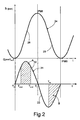
- the curve 24 indicates, as a function of time t corresponding to the angle of rotation of the shaft 23, the displacement h of a piston 21 through a suction stroke 28 and a compression or delivery stroke 29, between a bottom dead centre PMI and a top dead centre PMS.
- the sinusoidal curve 31 indicates the speed of the piston 21 itself once again as a function of the angle of rotation of the shaft 23.
- the curve 31 comprises a half-wave 32, which corresponds to the speed of the suction stroke of the corresponding piston 21, and a half-wave 33, which corresponds to the speed of the delivery stroke of the corresponding piston 21.
- the area under the half-wave 32 equivalent to the one under the half-wave 33, represents the volume of fuel that can be taken in through the intake pipe 10, i.e., it coincides with the displacement of the pumping element, whilst the area under the half-wave 33 represents the volume of fuel that may be delivered into the pipe 8.
- the on-off solenoid valve 27 ( Figure 1) is designed to be controlled in a chopped way by the control unit 16, as a function of the pressure of the fuel in the rail 6, and/or of the operating conditions of the engine 2.
- the control unit 16 controls opening of the solenoid valve 27 in Pulse Width Modulation (PWM), for a time interval, i.e., for a part of the suction stroke of the piston 21 of each of the two pumping elements 18.
- PWM Pulse Width Modulation
- the unit 16 is designed to modulate both the instant Tstart of start of opening of the solenoid valve 27, and the instant Tend of end of opening of the solenoid valve 27 itself, with respect to the instant To of start of the suction stroke of the pumping element 18.
- the solenoid valve 27 is opened with a certain delay with respect to the start of the suction stroke of the pumping element 18, and the amount (Tstart-To) of the delay is such that at the instant in which the solenoid valve 27 is opened, the intake valve 25 of the other pumping element 18, which at that moment is in the compression phase, is certainly closed.
- the instants Tstart and Tend are symmetrical with respect to the instant To of the bottom dead centre BDC and the instant Ti of the top dead centre TDC of the piston 21.
- the fuel is sent to the pumping element 18 when the latter is moving at a higher speed, i.e., when in the compression chamber there is the maximum negative pressure, so that opening of the intake valve 25 is favoured even at reduced pressure of the fuel in the intake pipe 10.
- the pumping element 18 i.e., of the part of the suction stroke in which intake is actually performed, and regulation of the angular phase of said suction with respect to the position of the piston 21.
- the delivery of the fuel of the pumping element 18 is carried out starting from a point Tm during the delivery stroke up to the end of said stroke.
- the two hatched areas A and B which are equivalent, indicate, respectively, the volume of fuel taken in and the volume of compressed fuel delivered. In this way, dosage of the fuel pumped is obtained exclusively by the on-off solenoid valve 27.
- FIG. 3 Represented in Figure 3 with a solid line, is the diagram 31 of operation of one of the two pumping elements 18, for example the bottom pumping element 18, whilst represented with the dashed and dotted line is the diagram 31' of the other pumping element 18, i.e., the top pumping element 18.
- the two pumping elements 18 have a common stretch of intake pipe 10; consequently, in the case of marked partialization of the suction, in the common pipe 10 there is a small amount of liquid fuel and a large amount of vapour.
- the intake valve 25 of a pumping element 18, for example the bottom pumping element 18, does not succeed in closing at the end of the suction stroke, but remains open for a stretch T1-Tc of the corresponding compression stroke.
- This stretch T1-Tc occurs simultaneously to the suction stroke of the other pumping element 18, i.e., the top one, during which the corresponding intake valve 25 is also open.
- the solid line 34 indicates the duration of the opening of the valve 25 of the bottom pumping element 18, whilst the dashed and dotted line 35 indicates the duration of the opening of the valve 25 of the top pumping element 18.
- the hatched area indicates the stretch T1-Tc of simultaneous opening of the two valves 25.
- the pumping element 18 that is in the delivery phase continues to suck in the fuel of the common intake pipe emptying it completely before the solenoid valve 27 re-opens.
- the stretch T1-Tc is equal to the entire part of the suction stroke of the pumping element 18 during suction, in which the solenoid valve 27 is closed, or is slightly shorter. In this way, dosage of the fuel compressed by the pump 7 is entirely performed by the on-off solenoid valve 27 with extreme precision, even for small flow rates.
- FIG 4 A different embodiment is illustrated in Figure 4, in which there is provided one on-off solenoid valve 27 for each of the two pumping elements 18.
- on-off solenoid valve 27 there may advantageously be employed one or more known electrically controlled injectors, which are normally used in internal-combustion engines, controlling them as solenoid valves.
- electrically controlled injectors which are normally used in internal-combustion engines, controlling them as solenoid valves.
- branched petrol/gas fuel injectors as on-off solenoid valves presents the following advantages:
- the delay of closing of the intake valve 25 of a pumping element 18 enables intake of part of the fuel remained in the common intake pipe 10 and being to go to the other pumping element 18, thus enabling a higher precision of dosage of the fuel sent at each pumping stroke.
- the two pumping elements 18 can be arranged in parallel and actuated in phase opposition by two different cams.
- the pump 7 can have a different number of pumping elements, for example three pumping elements actuated by a common cam with a phase offset of 120°. In this case, since the 180° suction stroke of each pumping element 18 is carried out in partial overlapping with the suction stroke of the other pumping elements, it is necessary to set an on-off solenoid valve on the branch of the suction pump of each pumping element, instead of on the branch of pipe common to the pumping elements.
Landscapes
- Engineering & Computer Science (AREA)
- Chemical & Material Sciences (AREA)
- Combustion & Propulsion (AREA)
- Mechanical Engineering (AREA)
- General Engineering & Computer Science (AREA)
- Fuel-Injection Apparatus (AREA)
- Jet Pumps And Other Pumps (AREA)
Abstract

Description
- The present invention relates to a high-pressure pump with a device for regulating the flow rate for a fuel injection system of an internal combustion engine.
- As is known, in modern internal combustion engines, the high-pressure pump is designed to send fuel to a common rail having a pre-set accumulation volume of pressurized fuel, for supplying a plurality of injectors associated to the cylinders of the engine. To obtain a proper atomization of the fuel, this must be brought to a very high pressure, in the region of 1600 bar in the conditions of maximum power of the engine. The pressure of the fuel required in the common rail is in general defined by an electronic control unit as a function of the operating conditions, i.e., the running conditions of the engine.
- Injection systems are known in which a by-pass solenoid valve, arranged on the delivery pipe of the pump, is controlled by the control unit for draining off directly the excess fuel just pumped into the usual fuel tank, before said fuel enters the common rail.
- Since the flow rate of the high-pressure pump in general depends upon the speed of rotation of the engine crankshaft, it must be sized so as to achieve the maximum flow-rate and pressure values required by the various operating conditions of the engine. In certain operating conditions, for example at the maximum speed but with low power of the engine shaft, the flow rate of the pump proves overabundant, and the fuel in excess is simply drained off into the tank. Consequently, these known regulation devices present the drawback of dissipating part of the work of compression of the high-pressure pump in the form of heat.
- Variable-flow-rate high-pressure pumps have been proposed to reduce the amount of fuel pumped when the engine functions at low power. In one of these pumps, the intake pipe is provided with a flow-rate regulation device comprising a restriction with a cross section that varies with continuity, which is controlled by the electronic-control unit as a function of the pressure required in the common rail and/or as a function of the operating conditions of the engine.
- In particular, the restriction in the intake pipe is supplied with a constant pressure difference ΔP of approximately 5 bar, supplied by an auxiliary pump. By varying with continuity the effective area of passage of the fuel, using a regulation solenoid valve, there is obtained a modulation of the amount taken in by the hydraulically connected pumping elements. The amount of fuel downstream of the regulation solenoid valve, i.e., the amount allowed at intake, is at a very low pressure and yields, at low flow rates, only a small contribution of force for opening the intake valve of the pumping element. Consequently, the usual return spring of the intake valve must be such as to guarantee opening thereof even at a minimum pressure downstream of the restriction. On the one hand, said spring must be calibrated in a very precise way, so that the pump proves relatively costly, and, on the other hand, there is always the risk that the intake valve will be unable to open on account of the negative pressure caused by the pumping element in the corresponding compression chamber, so that the pump does not function correctly and is highly subject to deterioration.
- The purpose of the invention is to provide a high-pressure fuel pump with a flow-rate regulation device which is of high reliability and of contained cost and will enable the drawbacks of fuel pumps of the known art to be overcome.
- According to the invention, the above purpose is achieved by a high-pressure pump with a flow-rate regulation device for a fuel-injection system of an internal combustion engine, comprising a number of pumping elements, which are actuated with reciprocating motion through corresponding suction and delivery strokes, each of said pumping elements being provided with a corresponding intake valve in communication with an intake pipe, and with a corresponding delivery valve in communication with an accumulation volume of pressurized fuel, said pump being characterized in that said regulation device comprises at least one solenoid valve for shut off of the fuel supplied to said pumping elements, said solenoid valve being set on said intake pipe and being actuated during the suction strokes of said pumping elements so that opening of said solenoid valve will take place with a certain delay with respect to the start of the suction strokes themselves.
- In particular, the shut-off solenoid valve has a cross section such as to enable it to supply each pumping element only with the fuel required in the corresponding suction stroke, and is designed to be controlled in a chopped way by a control unit, which controls opening thereof during an intermediate part of each suction stroke of said pumping elements.
- For a better understanding of the invention, there is provided a description of a preferred embodiment, by way of example and with the aid of the annexed drawings, in which:
- Figure 1 is a diagram of a fuel-injection system in an internal-combustion engine, comprising a high-pressure pump with a flow-rate regulation device according to one embodiment of the invention;
- Figure 2 is a diagram of the operation of the regulation device of Figure 1;
- Figure 3 is a diagram that illustrates an aspect of operation; and
- Figure 4 is a diagram of a fuel-injection system in an internal-combustion engine, comprising a high-pressure pump with a flow-rate regulation device according to a different embodiment of the invention.
- With reference to Figure 1,
number 1 designates, as a whole, a fuel-injection system for an internal-combustion engine 2, for example a four-stroke diesel engine. Theengine 2 comprises a plurality ofcylinders 3, for example four cylinders, which co-operate with corresponding pistons (not shown), which can be actuated for rotating an engine shaft 4. - The
injection system 1 comprises a plurality of electromagnetically controlled injectors 5, associated to thecylinders 3 and designed to inject therein the fuel at a high pressure. The injectors 5 are connected to an accumulation volume, which has a pre-set volume for one or more injectors 5. In the embodiment illustrated, the accumulation volume is formed by the usualcommon rail 6, connected to which are all the injectors 5. - The
common rail 6 is supplied with fuel at a high pressure by a high-pressure pump, as a whole designated by 7, via a delivery pipe 8. In turn, the high-pressure pump 7 is supplied by a low-pressure pump, for example anelectric pump 9, via anintake pipe 10 of thepump 7. Theelectric pump 9 is in general arranged in theusual fuel tank 11, into which there gives out adischarge pipe 12 for draining off the excess fuel of theinjection system 1. - The
common rail 6 is moreover provided with adrain solenoid valve 15 in communication with thedischarge pipe 12. Each injector 5 is designed to inject, into thecorresponding cylinder 3, an amount of fuel that varies between a minimum value and a maximum value, under the control of anelectronic control unit 16, which can consist of the usual microprocessor control unit of theengine 2. - The
control unit 16 is designed to receive signals indicating the operating conditions of theengine 2, such as the position of the accelerator pedal and the r.p.m. of the engine shaft 4, which are generated by corresponding sensors not shown, as well as the pressure of the fuel in thecommon rail 6, detected by apressure sensor 17. By processing said signals received by means of an appropriate software, thecontrol unit 16 controls the instant and duration of actuation of the individual injectors 5. Furthermore, thecontrol unit 16 controls opening and closing of thedischarge solenoid valve 15. Consequently, thedischarge pipe 12 conveys towards thetank 11 both the drained fuel of the injectors 5 and the possible excess fuel in thecommon rail 6, discharged by thesolenoid valve 15. - The high-
pressure pump 7 comprises a pair ofpumping elements 18, each formed by acylinder 19 having acompression chamber 20, in which there slides apiston 21, which has a reciprocating motion, consisting of a suction stroke and a delivery stroke. Eachcompression chamber 20 is provided with acorresponding intake valve 25 and acorresponding delivery valve 30. Thevalves intake valves 25 are in communication with theintake pipe 10 common to both of them, whilst the twodelivery valves 30 are in communication with the delivery pipe 8 common to them. - In particular, the
piston 21 is actuated by acam 22 carried by ashaft 23 for actuation of thepump 7. In the embodiment described herein, the twopumping elements 18 are coaxial and opposite to one another, and are actuated by asingle cam 22. - The
shaft 23 is connected to the engine shaft 4, via amotion transmitting device 26, such that thecam 22 controls a compression stroke of apiston 21 for each injection by the injectors 5 into therespective cylinders 3 of theengine 2. - In the
tank 11, the fuel is at atmospheric pressure. In use, theelectric pump 9 compresses the fuel to a low pressure, for example in the region of just 2-3 bar. In turn, the high-pressure pump 7 compresses the fuel received from theintake pipe 10 so as to send the fuel at a high pressure, for example in the region of 1600 bar, to thecommon rail 6, via the delivery pipe 8. - According to one embodiment of the invention, the flow rate of the
pump 7 is controlled exclusively by a regulation device arranged on theintake pipe 10. The regulation device comprises a shut-offsolenoid valve 27, of the on-off type, which is actuated at each suction stroke of the twopumping elements 18. Advantageously, the solenoid valve has a pumping section such as to enable direct supply of eachpumping element 18 during only a portion of the corresponding suction stroke. - In particular, the displacement of each
pumping element 18 is of the same order of magnitude as the maximum volume of fuel that an injector 5 can inject into acylinder 3 of theengine 2 in the corresponding injection phase. Consequently, if the injector 5 is controlled for injecting an amount of fuel smaller than the maximum one, it is sufficient for thepumping element 18 to take in fuel for a part only of the suction stroke of thepiston 21. - In the diagram of Figure 2, the
curve 24 indicates, as a function of time t corresponding to the angle of rotation of theshaft 23, the displacement h of apiston 21 through asuction stroke 28 and a compression ordelivery stroke 29, between a bottom dead centre PMI and a top dead centre PMS. Furthermore, thesinusoidal curve 31 indicates the speed of thepiston 21 itself once again as a function of the angle of rotation of theshaft 23. Thecurve 31 comprises a half-wave 32, which corresponds to the speed of the suction stroke of thecorresponding piston 21, and a half-wave 33, which corresponds to the speed of the delivery stroke of thecorresponding piston 21. The area under the half-wave 32, equivalent to the one under the half-wave 33, represents the volume of fuel that can be taken in through theintake pipe 10, i.e., it coincides with the displacement of the pumping element, whilst the area under the half-wave 33 represents the volume of fuel that may be delivered into the pipe 8. - The on-off solenoid valve 27 (Figure 1) is designed to be controlled in a chopped way by the
control unit 16, as a function of the pressure of the fuel in therail 6, and/or of the operating conditions of theengine 2. In particular, thecontrol unit 16 controls opening of thesolenoid valve 27 in Pulse Width Modulation (PWM), for a time interval, i.e., for a part of the suction stroke of thepiston 21 of each of the twopumping elements 18. - More precisely, the
unit 16 is designed to modulate both the instant Tstart of start of opening of thesolenoid valve 27, and the instant Tend of end of opening of thesolenoid valve 27 itself, with respect to the instant To of start of the suction stroke of thepumping element 18. In particular, thesolenoid valve 27 is opened with a certain delay with respect to the start of the suction stroke of thepumping element 18, and the amount (Tstart-To) of the delay is such that at the instant in which thesolenoid valve 27 is opened, theintake valve 25 of theother pumping element 18, which at that moment is in the compression phase, is certainly closed. In this way, since the twopumping elements 18 are actuated in phase opposition, the fuel sent to thepump 7, through theintake pipe 10, is sucked in only by thepumping element 18 which at that instant carries out the suction stroke, in so far as theintake valve 25 of theother pumping element 18 which has started the compression phase is closed. - Advantageously, the instants Tstart and Tend are symmetrical with respect to the instant To of the bottom dead centre BDC and the instant Ti of the top dead centre TDC of the
piston 21. In this way, the fuel is sent to thepumping element 18 when the latter is moving at a higher speed, i.e., when in the compression chamber there is the maximum negative pressure, so that opening of theintake valve 25 is favoured even at reduced pressure of the fuel in theintake pipe 10. Furthermore, in this way, there is obtained simultaneously both regulation of the duration of suction by thepumping element 18, i.e., of the part of the suction stroke in which intake is actually performed, and regulation of the angular phase of said suction with respect to the position of thepiston 21. - On the contrary, the delivery of the fuel of the pumping
element 18 is carried out starting from a point Tm during the delivery stroke up to the end of said stroke. In Figure 2, the two hatched areas A and B, which are equivalent, indicate, respectively, the volume of fuel taken in and the volume of compressed fuel delivered. In this way, dosage of the fuel pumped is obtained exclusively by the on-offsolenoid valve 27. - Since the head supplied by the
electric pump 9 is known and since the pressure in theintake pipe 10 is practically constant, on-off operation of thesolenoid valve 27 enables introduction, with excellent resolution, of a pre-defined amount of fuel into the volume upstream of eachcompression chamber 20. - Represented in Figure 3 with a solid line, is the diagram 31 of operation of one of the two
pumping elements 18, for example thebottom pumping element 18, whilst represented with the dashed and dotted line is the diagram 31' of theother pumping element 18, i.e., thetop pumping element 18. In the diagram considered, the twopumping elements 18 have a common stretch ofintake pipe 10; consequently, in the case of marked partialization of the suction, in thecommon pipe 10 there is a small amount of liquid fuel and a large amount of vapour. Theintake valve 25 of apumping element 18, for example thebottom pumping element 18, does not succeed in closing at the end of the suction stroke, but remains open for a stretch T1-Tc of the corresponding compression stroke. This stretch T1-Tc occurs simultaneously to the suction stroke of theother pumping element 18, i.e., the top one, during which thecorresponding intake valve 25 is also open. In Figure 3, thesolid line 34 indicates the duration of the opening of thevalve 25 of thebottom pumping element 18, whilst the dashed and dottedline 35 indicates the duration of the opening of thevalve 25 of thetop pumping element 18. The hatched area indicates the stretch T1-Tc of simultaneous opening of the twovalves 25. - In this way, the pumping
element 18 that is in the delivery phase, continues to suck in the fuel of the common intake pipe emptying it completely before thesolenoid valve 27 re-opens. Preferably, the stretch T1-Tc is equal to the entire part of the suction stroke of thepumping element 18 during suction, in which thesolenoid valve 27 is closed, or is slightly shorter. In this way, dosage of the fuel compressed by thepump 7 is entirely performed by the on-offsolenoid valve 27 with extreme precision, even for small flow rates. - A different embodiment is illustrated in Figure 4, in which there is provided one on-off
solenoid valve 27 for each of the twopumping elements 18. - This embodiment enables both the instant of opening Tstart and the instant of closing Tend of each on-off
solenoid valve 27 to be varied, thus enabling synchronization of the opening of the on-offsolenoid valve 27 with the time interval in which thecorresponding pumping element 18 moves with the higher speed and hence when in the compression chamber of thepumping element 18 itself the negative pressure is maximum. - It is evident that in this way there is the certainty that the amount introduced by the on-off
solenoid valve 27 is entirely taken in by thecorresponding pumping element 18, with evident beneficial effects on the accuracy of the amount sent in each cycle by thepump 7 to theaccumulation volume 6. Furthermore, in this embodiment sizing of the springs of theintake valves 25 of thepumping elements 18 is less critical, in so far as any possible asymmetry between the latter have very small consequences on the symmetry of suction of thepumping elements 18. - According to another aspect of the invention, as on-off
solenoid valve 27 there may advantageously be employed one or more known electrically controlled injectors, which are normally used in internal-combustion engines, controlling them as solenoid valves. In particular, the use of branched petrol/gas fuel injectors as on-off solenoid valves presents the following advantages: - known and asserted technology for the fabrication of the components;
- lower investment cost, with consequent lower unit cost of the injection system;
- ready availability from various suppliers;
- practically the same control as the one necessary for operation as electrically controlled injector; and
- operation of the injector also as safety valve of the system.
- From the above description, the advantages of the high-pressure pump with a device for regulating the flow rate of fuel according to the invention as compared to the known art are evident. In particular, at each injection, there is sent to each pumping
element 18 only the fuel required for the simultaneous injection, so that the function of dosage of the fuel is performed substantially by the on-offsolenoid valve 27 and is a function of the pressure difference across the on-offsolenoid valve 27 and its cross section. Furthermore, actuation of thesolenoid valve 27 in a chopped way, by modulating both the instant of start and the instant of end of the effective suction, during the suction stroke of the corresponding pumping element, there is obtained a symmetry with respect to the entire suction stroke such as to concentrate the supply of fuel to thechamber 20 in the period of maximum speed of thepiston 21. - Finally, in the case of extreme partialization of the suction, the delay of closing of the
intake valve 25 of apumping element 18 enables intake of part of the fuel remained in thecommon intake pipe 10 and being to go to theother pumping element 18, thus enabling a higher precision of dosage of the fuel sent at each pumping stroke. - It is understood that various modifications and improvements can be made to the high-pressure pump and to the corresponding regulation device described above, without departing from the scope of the claims. For example, it is possible to eliminate the
motion transmitting device 26 and to actuate theshaft 23 of the high-pressure pump 7 at a differently controlled rate. Also thedrain solenoid valve 15 of the fuel from theaccumulation device 6 can be eliminated. - Furthermore, the two
pumping elements 18 can be arranged in parallel and actuated in phase opposition by two different cams. Finally, thepump 7 can have a different number of pumping elements, for example three pumping elements actuated by a common cam with a phase offset of 120°. In this case, since the 180° suction stroke of each pumpingelement 18 is carried out in partial overlapping with the suction stroke of the other pumping elements, it is necessary to set an on-off solenoid valve on the branch of the suction pump of each pumping element, instead of on the branch of pipe common to the pumping elements.
Claims (11)
- A high-pressure pump (7) with a device (27) for regulation of the flow rate for a fuel-injection system (1) of an internal-combustion engine, comprising at least one pumping element (18), which is actuated with reciprocating motion through corresponding suction and delivery strokes and is provided with a corresponding intake valve (25) in communication with an intake pipe (10), and a corresponding delivery valve (30) in communication with an accumulation volume (6) of pressurized fuel; said pump (7) being characterized in that said regulation device comprises at least one on-off solenoid valve (27) for shutting off the fuel supplied to said pumping element (18), said solenoid valve (27) being set on said intake pipe (10) and being actuated during the suction strokes of said pumping element (18) with a certain delay with respect to the start of the suction strokes themselves.
- The high-pressure pump according to Claim 1, characterized in that opening of said solenoid valve (27) occurs at a point corresponding to an intermediate part (Tstart-Tend) of each suction stroke of said pumping element (18).
- The high-pressure pump according to Claim 2, characterized in that said intermediate part (Tstart-Tend) is symmetrical with respect to said suction stroke.
- The high-pressure pump according to Claim 2 or 3, characterized in that said intermediate part (Tstart-Tend) is obtained by varying both the instant of start (Tstart) and the instant of end (Tend) of opening of said solenoid valve (27).
- The high-pressure pump according to any one of the preceding claims, characterized in that said solenoid valve (27) is designed to be controlled in a chopped way by a control unit (16) as a function of the conditions of operation of said engine (2).
- The high-pressure pump according to any one of the preceding claims, characterized in that said solenoid valve (27) has a cross section such as to enable it to supply said pumping element (18) only with the fuel required for the corresponding suction.
- The high-pressure pump according to any one of the preceding claims, with a number of pumping elements (18), each equipped with a corresponding intake valve (25), said intake valves (25) being in communication with a common intake pipe (10), said pump being characterized in that said solenoid valve (27) is set on said common intake pipe (10).
- The high-pressure pump according to Claim 7, comprising a pair of pumping elements (18) actuated in phase opposition, characterized in that said regulation device (27) is actuated in synchronism with each suction stroke of said pumping elements (18) as a function of the operating conditions of said engine (2).
- The high-pressure pump according to Claim 7 or 8, characterized in that the delay with which said solenoid valve (27) is actuated with respect to the start of the suction stroke of one of said pumping elements (18) is a function of the fuel supplied to the other of said pumping elements (18) during its previous suction stroke.
- The high-pressure pump according to any one of Claims 1 to 6, with a number of pumping elements (18), each equipped with a corresponding intake valve (25) set on a corresponding suction pump, characterized in that it comprises a number of said solenoid valves (27) equal to the number of said pumping elements (18), each of said solenoid valves (27) being set on the suction pipe of a corresponding pumping element (18).
- The high-pressure pump according to Claim 10, comprising a pair of pumping elements (18) actuated in phase opposition, characterized in that said solenoid valves (27) are actuated in synchronism with the suction strokes of the corresponding pumping elements (18) as a function of the conditions of operation of said engine (2).
Priority Applications (6)
| Application Number | Priority Date | Filing Date | Title |
|---|---|---|---|
| ES04425840T ES2280931T3 (en) | 2004-11-12 | 2004-11-12 | HIGH PRESSURE PUMP WITH A FLOW REGULATION DEVICE FOR A FUEL INJECTION SYSTEM. |
| AT04425840T ATE355457T1 (en) | 2004-11-12 | 2004-11-12 | HIGH PRESSURE PUMP HAVING A FLOW CONTROL DEVICE FOR A FUEL INJECTION SYSTEM |
| EP04425840A EP1657434B1 (en) | 2004-11-12 | 2004-11-12 | A high-pressure pump with a device for regulating the flow rate for a fuel-injection system |
| DE602004005051T DE602004005051T2 (en) | 2004-11-12 | 2004-11-12 | High-pressure pump with a device for controlling the flow for a fuel injection system |
| US11/114,091 US7263979B2 (en) | 2004-11-12 | 2005-04-26 | High-pressure pump with a device for regulating the flow rate for a fuel-injection system |
| JP2005132727A JP4275646B2 (en) | 2004-11-12 | 2005-04-28 | High pressure pump for fuel injection system with flow regulator |
Applications Claiming Priority (1)
| Application Number | Priority Date | Filing Date | Title |
|---|---|---|---|
| EP04425840A EP1657434B1 (en) | 2004-11-12 | 2004-11-12 | A high-pressure pump with a device for regulating the flow rate for a fuel-injection system |
Publications (2)
| Publication Number | Publication Date |
|---|---|
| EP1657434A1 true EP1657434A1 (en) | 2006-05-17 |
| EP1657434B1 EP1657434B1 (en) | 2007-02-28 |
Family
ID=34932879
Family Applications (1)
| Application Number | Title | Priority Date | Filing Date |
|---|---|---|---|
| EP04425840A Expired - Lifetime EP1657434B1 (en) | 2004-11-12 | 2004-11-12 | A high-pressure pump with a device for regulating the flow rate for a fuel-injection system |
Country Status (6)
| Country | Link |
|---|---|
| US (1) | US7263979B2 (en) |
| EP (1) | EP1657434B1 (en) |
| JP (1) | JP4275646B2 (en) |
| AT (1) | ATE355457T1 (en) |
| DE (1) | DE602004005051T2 (en) |
| ES (1) | ES2280931T3 (en) |
Cited By (2)
| Publication number | Priority date | Publication date | Assignee | Title |
|---|---|---|---|---|
| ITUB20153528A1 (en) * | 2015-09-10 | 2017-03-10 | Bosch Gmbh Robert | HIGH PRESSURE PUMP UNIT FOR FUEL SUPPLEMENT, PREFERABLY GASOIL, TO AN INTERNAL COMBUSTION ENGINE |
| CN108779732A (en) * | 2016-03-17 | 2018-11-09 | 罗伯特·博世有限公司 | Method for ascertaining a target value for a manipulated variable for actuating a low-pressure pump |
Families Citing this family (5)
| Publication number | Priority date | Publication date | Assignee | Title |
|---|---|---|---|---|
| JP4779483B2 (en) * | 2005-07-21 | 2011-09-28 | 株式会社デンソー | Fuel injection control device |
| EP1865193B1 (en) * | 2006-06-09 | 2010-11-03 | C.R.F. Società Consortile per Azioni | Fuel injection system for an internal combustion engine |
| EP2039920B1 (en) * | 2007-09-21 | 2010-09-08 | Magneti Marelli S.p.A. | Control method for a direct injection system of the common-rail type provided with a shut-off valve for controlling the flow of a high-pressure fuel pump |
| US9989026B2 (en) * | 2012-02-17 | 2018-06-05 | Ford Global Technologies, Llc | Fuel pump with quiet rotating suction valve |
| CN102989711B (en) * | 2012-12-04 | 2014-12-03 | 中国第一汽车股份有限公司无锡油泵油嘴研究所 | Impurity collecting device for oil sprayer |
Citations (5)
| Publication number | Priority date | Publication date | Assignee | Title |
|---|---|---|---|---|
| EP1219827A1 (en) * | 2000-12-29 | 2002-07-03 | C.R.F. Società Consortile per Azioni | Fuel injection system for internal combustion engines, with a high pressure pump having a shaped cam |
| EP1241338A2 (en) * | 2001-03-15 | 2002-09-18 | Hitachi, Ltd. | Fuel supply system |
| EP1298316A2 (en) * | 2001-09-26 | 2003-04-02 | DEUTZ Aktiengesellschaft | Fuel injection system |
| DE10345154A1 (en) * | 2002-09-30 | 2004-04-22 | Denso Corp., Kariya | High pressure fuel pump for an internal combustion engine |
| EP1469190A1 (en) * | 2003-04-15 | 2004-10-20 | Denso Corporation | High-pressure fuel supplying apparatus |
Family Cites Families (13)
| Publication number | Priority date | Publication date | Assignee | Title |
|---|---|---|---|---|
| CH674243A5 (en) * | 1987-07-08 | 1990-05-15 | Dereco Dieselmotoren Forschung | |
| DE19549108A1 (en) * | 1995-12-29 | 1997-07-03 | Bosch Gmbh Robert | High-pressure fuel generation system for a fuel injection system used in internal combustion engines |
| DE19846157A1 (en) * | 1998-10-07 | 2000-04-13 | Bosch Gmbh Robert | Pump arrangement for high-pressure fuel generation |
| DE19860672A1 (en) * | 1998-12-29 | 2000-07-13 | Bosch Gmbh Robert | Piston pump for high-pressure fuel generation |
| US6439199B2 (en) * | 2000-04-20 | 2002-08-27 | Bosch Rexroth Corporation | Pilot operated throttling valve for constant flow pump |
| JP4123729B2 (en) * | 2001-03-15 | 2008-07-23 | 株式会社日立製作所 | Control method of fuel supply device |
| US6899083B2 (en) * | 2001-09-10 | 2005-05-31 | Stanadyne Corporation | Hybrid demand control for hydraulic pump |
| DE10155247B4 (en) * | 2001-11-09 | 2006-08-24 | Siemens Ag | Injection system with emergency function |
| DE10205186A1 (en) * | 2002-02-08 | 2003-08-21 | Bosch Gmbh Robert | Fuel injection device for an internal combustion engine |
| DE10218021A1 (en) * | 2002-04-23 | 2003-11-06 | Bosch Gmbh Robert | Fuel injection device for an internal combustion engine |
| JP3855861B2 (en) * | 2002-06-28 | 2006-12-13 | トヨタ自動車株式会社 | High pressure fuel supply device for internal combustion engine |
| JP4207834B2 (en) * | 2003-06-27 | 2009-01-14 | 株式会社デンソー | Accumulated fuel injection system |
| JP4042057B2 (en) * | 2003-11-04 | 2008-02-06 | 株式会社デンソー | Valve opening adjustment device and common rail fuel injection device |
-
2004
- 2004-11-12 AT AT04425840T patent/ATE355457T1/en not_active IP Right Cessation
- 2004-11-12 ES ES04425840T patent/ES2280931T3/en not_active Expired - Lifetime
- 2004-11-12 DE DE602004005051T patent/DE602004005051T2/en not_active Expired - Lifetime
- 2004-11-12 EP EP04425840A patent/EP1657434B1/en not_active Expired - Lifetime
-
2005
- 2005-04-26 US US11/114,091 patent/US7263979B2/en not_active Expired - Lifetime
- 2005-04-28 JP JP2005132727A patent/JP4275646B2/en not_active Expired - Lifetime
Patent Citations (5)
| Publication number | Priority date | Publication date | Assignee | Title |
|---|---|---|---|---|
| EP1219827A1 (en) * | 2000-12-29 | 2002-07-03 | C.R.F. Società Consortile per Azioni | Fuel injection system for internal combustion engines, with a high pressure pump having a shaped cam |
| EP1241338A2 (en) * | 2001-03-15 | 2002-09-18 | Hitachi, Ltd. | Fuel supply system |
| EP1298316A2 (en) * | 2001-09-26 | 2003-04-02 | DEUTZ Aktiengesellschaft | Fuel injection system |
| DE10345154A1 (en) * | 2002-09-30 | 2004-04-22 | Denso Corp., Kariya | High pressure fuel pump for an internal combustion engine |
| EP1469190A1 (en) * | 2003-04-15 | 2004-10-20 | Denso Corporation | High-pressure fuel supplying apparatus |
Cited By (4)
| Publication number | Priority date | Publication date | Assignee | Title |
|---|---|---|---|---|
| ITUB20153528A1 (en) * | 2015-09-10 | 2017-03-10 | Bosch Gmbh Robert | HIGH PRESSURE PUMP UNIT FOR FUEL SUPPLEMENT, PREFERABLY GASOIL, TO AN INTERNAL COMBUSTION ENGINE |
| WO2017042016A1 (en) * | 2015-09-10 | 2017-03-16 | Robert Bosch Gmbh | High-pressure pump unit for supplying fuel, preferably diesel fuel, to an internal combustion engine |
| CN108779732A (en) * | 2016-03-17 | 2018-11-09 | 罗伯特·博世有限公司 | Method for ascertaining a target value for a manipulated variable for actuating a low-pressure pump |
| CN108779732B (en) * | 2016-03-17 | 2021-04-02 | 罗伯特·博世有限公司 | Method for determining a target value of a control variable for actuating a low-pressure pump |
Also Published As
| Publication number | Publication date |
|---|---|
| ES2280931T3 (en) | 2007-09-16 |
| ATE355457T1 (en) | 2006-03-15 |
| JP2006138313A (en) | 2006-06-01 |
| EP1657434B1 (en) | 2007-02-28 |
| US20060104826A1 (en) | 2006-05-18 |
| US7263979B2 (en) | 2007-09-04 |
| JP4275646B2 (en) | 2009-06-10 |
| DE602004005051D1 (en) | 2007-04-12 |
| DE602004005051T2 (en) | 2007-11-22 |
Similar Documents
| Publication | Publication Date | Title |
|---|---|---|
| US7182067B2 (en) | Storage-volume fuel injection system for an internal combustion engine | |
| US7261087B2 (en) | High-pressure variable-flow-rate pump for a fuel-injection system | |
| EP1219827B1 (en) | Fuel injection system for internal combustion engines, with a high pressure pump having a shaped cam | |
| KR100937981B1 (en) | Improving Fuel Injection Systems for Internal Combustion Engines | |
| US7980223B2 (en) | Accumulation-volume fuel injection system for an internal-combustion engine | |
| EP1674716B1 (en) | Fuel injection system comprising a high-pressure variable-delivery pump | |
| US7198034B2 (en) | Method and system for the direct injection of fuel into an internal combustion engine | |
| EP1674718B1 (en) | Internal combustion engine storage-volume fuel injection system | |
| EP1657434B1 (en) | A high-pressure pump with a device for regulating the flow rate for a fuel-injection system | |
| US7063073B2 (en) | Method for the direct injection of fuel into an internal combustion engine | |
| US7395812B2 (en) | Fuel-injection system for an internal-combustion engine | |
| JP4389417B2 (en) | Fuel supply apparatus for in-cylinder injection internal combustion engine | |
| JP4329755B2 (en) | High pressure fuel pump for internal combustion engine | |
| JPH04339152A (en) | Control device for fuel injection of internal combustion engine | |
| JP2011185164A (en) | Control device of internal combustion engine | |
| JP2006152852A (en) | Fuel piping for internal combustion engines | |
| JP2023175074A (en) | Method and device for controlling fuel injection during starting of an internal combustion engine |
Legal Events
| Date | Code | Title | Description |
|---|---|---|---|
| PUAI | Public reference made under article 153(3) epc to a published international application that has entered the european phase |
Free format text: ORIGINAL CODE: 0009012 |
|
| 17P | Request for examination filed |
Effective date: 20060222 |
|
| AK | Designated contracting states |
Kind code of ref document: A1 Designated state(s): AT BE BG CH CY CZ DE DK EE ES FI FR GB GR HU IE IS IT LI LU MC NL PL PT RO SE SI SK TR |
|
| AX | Request for extension of the european patent |
Extension state: AL HR LT LV MK YU |
|
| GRAP | Despatch of communication of intention to grant a patent |
Free format text: ORIGINAL CODE: EPIDOSNIGR1 |
|
| RIN1 | Information on inventor provided before grant (corrected) |
Inventor name: DE MICHELE, ONOFRIO Inventor name: DE MATTHAEIS, SISTO LUIGI Inventor name: RICCO, RAFFAELE Inventor name: RICCO, MARIO |
|
| GRAS | Grant fee paid |
Free format text: ORIGINAL CODE: EPIDOSNIGR3 |
|
| AKX | Designation fees paid |
Designated state(s): AT BE BG CH CY CZ DE DK EE ES FI FR GB GR HU IE IS IT LI LU MC NL PL PT RO SE SI SK TR |
|
| GRAA | (expected) grant |
Free format text: ORIGINAL CODE: 0009210 |
|
| AK | Designated contracting states |
Kind code of ref document: B1 Designated state(s): AT BE BG CH CY CZ DE DK EE ES FI FR GB GR HU IE IS IT LI LU MC NL PL PT RO SE SI SK TR |
|
| PG25 | Lapsed in a contracting state [announced via postgrant information from national office to epo] |
Ref country code: BE Free format text: LAPSE BECAUSE OF FAILURE TO SUBMIT A TRANSLATION OF THE DESCRIPTION OR TO PAY THE FEE WITHIN THE PRESCRIBED TIME-LIMIT Effective date: 20070228 Ref country code: SI Free format text: LAPSE BECAUSE OF FAILURE TO SUBMIT A TRANSLATION OF THE DESCRIPTION OR TO PAY THE FEE WITHIN THE PRESCRIBED TIME-LIMIT Effective date: 20070228 Ref country code: FI Free format text: LAPSE BECAUSE OF FAILURE TO SUBMIT A TRANSLATION OF THE DESCRIPTION OR TO PAY THE FEE WITHIN THE PRESCRIBED TIME-LIMIT Effective date: 20070228 Ref country code: DK Free format text: LAPSE BECAUSE OF FAILURE TO SUBMIT A TRANSLATION OF THE DESCRIPTION OR TO PAY THE FEE WITHIN THE PRESCRIBED TIME-LIMIT Effective date: 20070228 Ref country code: CH Free format text: LAPSE BECAUSE OF FAILURE TO SUBMIT A TRANSLATION OF THE DESCRIPTION OR TO PAY THE FEE WITHIN THE PRESCRIBED TIME-LIMIT Effective date: 20070228 Ref country code: NL Free format text: LAPSE BECAUSE OF FAILURE TO SUBMIT A TRANSLATION OF THE DESCRIPTION OR TO PAY THE FEE WITHIN THE PRESCRIBED TIME-LIMIT Effective date: 20070228 Ref country code: PL Free format text: LAPSE BECAUSE OF FAILURE TO SUBMIT A TRANSLATION OF THE DESCRIPTION OR TO PAY THE FEE WITHIN THE PRESCRIBED TIME-LIMIT Effective date: 20070228 Ref country code: AT Free format text: LAPSE BECAUSE OF FAILURE TO SUBMIT A TRANSLATION OF THE DESCRIPTION OR TO PAY THE FEE WITHIN THE PRESCRIBED TIME-LIMIT Effective date: 20070228 Ref country code: LI Free format text: LAPSE BECAUSE OF FAILURE TO SUBMIT A TRANSLATION OF THE DESCRIPTION OR TO PAY THE FEE WITHIN THE PRESCRIBED TIME-LIMIT Effective date: 20070228 |
|
| REG | Reference to a national code |
Ref country code: GB Ref legal event code: FG4D |
|
| REG | Reference to a national code |
Ref country code: CH Ref legal event code: EP |
|
| REF | Corresponds to: |
Ref document number: 602004005051 Country of ref document: DE Date of ref document: 20070412 Kind code of ref document: P |
|
| REG | Reference to a national code |
Ref country code: IE Ref legal event code: FG4D |
|
| REG | Reference to a national code |
Ref country code: SE Ref legal event code: TRGR |
|
| PG25 | Lapsed in a contracting state [announced via postgrant information from national office to epo] |
Ref country code: BG Free format text: LAPSE BECAUSE OF FAILURE TO SUBMIT A TRANSLATION OF THE DESCRIPTION OR TO PAY THE FEE WITHIN THE PRESCRIBED TIME-LIMIT Effective date: 20070528 |
|
| PG25 | Lapsed in a contracting state [announced via postgrant information from national office to epo] |
Ref country code: IS Free format text: LAPSE BECAUSE OF FAILURE TO SUBMIT A TRANSLATION OF THE DESCRIPTION OR TO PAY THE FEE WITHIN THE PRESCRIBED TIME-LIMIT Effective date: 20070628 |
|
| ET | Fr: translation filed | ||
| PG25 | Lapsed in a contracting state [announced via postgrant information from national office to epo] |
Ref country code: PT Free format text: LAPSE BECAUSE OF FAILURE TO SUBMIT A TRANSLATION OF THE DESCRIPTION OR TO PAY THE FEE WITHIN THE PRESCRIBED TIME-LIMIT Effective date: 20070730 |
|
| NLV1 | Nl: lapsed or annulled due to failure to fulfill the requirements of art. 29p and 29m of the patents act | ||
| REG | Reference to a national code |
Ref country code: CH Ref legal event code: PL |
|
| REG | Reference to a national code |
Ref country code: ES Ref legal event code: FG2A Ref document number: 2280931 Country of ref document: ES Kind code of ref document: T3 |
|
| PG25 | Lapsed in a contracting state [announced via postgrant information from national office to epo] |
Ref country code: SK Free format text: LAPSE BECAUSE OF FAILURE TO SUBMIT A TRANSLATION OF THE DESCRIPTION OR TO PAY THE FEE WITHIN THE PRESCRIBED TIME-LIMIT Effective date: 20070228 |
|
| PG25 | Lapsed in a contracting state [announced via postgrant information from national office to epo] |
Ref country code: RO Free format text: LAPSE BECAUSE OF FAILURE TO SUBMIT A TRANSLATION OF THE DESCRIPTION OR TO PAY THE FEE WITHIN THE PRESCRIBED TIME-LIMIT Effective date: 20070228 Ref country code: CZ Free format text: LAPSE BECAUSE OF FAILURE TO SUBMIT A TRANSLATION OF THE DESCRIPTION OR TO PAY THE FEE WITHIN THE PRESCRIBED TIME-LIMIT Effective date: 20070228 |
|
| PLBE | No opposition filed within time limit |
Free format text: ORIGINAL CODE: 0009261 |
|
| STAA | Information on the status of an ep patent application or granted ep patent |
Free format text: STATUS: NO OPPOSITION FILED WITHIN TIME LIMIT |
|
| 26N | No opposition filed |
Effective date: 20071129 |
|
| PG25 | Lapsed in a contracting state [announced via postgrant information from national office to epo] |
Ref country code: GR Free format text: LAPSE BECAUSE OF FAILURE TO SUBMIT A TRANSLATION OF THE DESCRIPTION OR TO PAY THE FEE WITHIN THE PRESCRIBED TIME-LIMIT Effective date: 20070529 |
|
| PG25 | Lapsed in a contracting state [announced via postgrant information from national office to epo] |
Ref country code: MC Free format text: LAPSE BECAUSE OF NON-PAYMENT OF DUE FEES Effective date: 20071130 |
|
| PG25 | Lapsed in a contracting state [announced via postgrant information from national office to epo] |
Ref country code: IE Free format text: LAPSE BECAUSE OF NON-PAYMENT OF DUE FEES Effective date: 20071112 |
|
| PG25 | Lapsed in a contracting state [announced via postgrant information from national office to epo] |
Ref country code: EE Free format text: LAPSE BECAUSE OF FAILURE TO SUBMIT A TRANSLATION OF THE DESCRIPTION OR TO PAY THE FEE WITHIN THE PRESCRIBED TIME-LIMIT Effective date: 20070228 |
|
| PG25 | Lapsed in a contracting state [announced via postgrant information from national office to epo] |
Ref country code: CY Free format text: LAPSE BECAUSE OF FAILURE TO SUBMIT A TRANSLATION OF THE DESCRIPTION OR TO PAY THE FEE WITHIN THE PRESCRIBED TIME-LIMIT Effective date: 20070228 |
|
| PG25 | Lapsed in a contracting state [announced via postgrant information from national office to epo] |
Ref country code: LU Free format text: LAPSE BECAUSE OF NON-PAYMENT OF DUE FEES Effective date: 20071112 |
|
| PG25 | Lapsed in a contracting state [announced via postgrant information from national office to epo] |
Ref country code: TR Free format text: LAPSE BECAUSE OF FAILURE TO SUBMIT A TRANSLATION OF THE DESCRIPTION OR TO PAY THE FEE WITHIN THE PRESCRIBED TIME-LIMIT Effective date: 20070228 Ref country code: HU Free format text: LAPSE BECAUSE OF FAILURE TO SUBMIT A TRANSLATION OF THE DESCRIPTION OR TO PAY THE FEE WITHIN THE PRESCRIBED TIME-LIMIT Effective date: 20070901 |
|
| REG | Reference to a national code |
Ref country code: FR Ref legal event code: PLFP Year of fee payment: 12 |
|
| REG | Reference to a national code |
Ref country code: FR Ref legal event code: PLFP Year of fee payment: 13 |
|
| REG | Reference to a national code |
Ref country code: FR Ref legal event code: PLFP Year of fee payment: 14 |
|
| PGFP | Annual fee paid to national office [announced via postgrant information from national office to epo] |
Ref country code: GB Payment date: 20231019 Year of fee payment: 20 |
|
| PGFP | Annual fee paid to national office [announced via postgrant information from national office to epo] |
Ref country code: ES Payment date: 20231201 Year of fee payment: 20 |
|
| PGFP | Annual fee paid to national office [announced via postgrant information from national office to epo] |
Ref country code: SE Payment date: 20231020 Year of fee payment: 20 Ref country code: IT Payment date: 20231019 Year of fee payment: 20 Ref country code: FR Payment date: 20231020 Year of fee payment: 20 Ref country code: DE Payment date: 20231019 Year of fee payment: 20 |
|
| REG | Reference to a national code |
Ref country code: DE Ref legal event code: R071 Ref document number: 602004005051 Country of ref document: DE |
|
| REG | Reference to a national code |
Ref country code: ES Ref legal event code: FD2A Effective date: 20241126 |
|
| REG | Reference to a national code |
Ref country code: GB Ref legal event code: PE20 Expiry date: 20241111 |
|
| REG | Reference to a national code |
Ref country code: SE Ref legal event code: EUG |
|
| PG25 | Lapsed in a contracting state [announced via postgrant information from national office to epo] |
Ref country code: GB Free format text: LAPSE BECAUSE OF EXPIRATION OF PROTECTION Effective date: 20241111 |
|
| PG25 | Lapsed in a contracting state [announced via postgrant information from national office to epo] |
Ref country code: ES Free format text: LAPSE BECAUSE OF EXPIRATION OF PROTECTION Effective date: 20241113 |
|
| PG25 | Lapsed in a contracting state [announced via postgrant information from national office to epo] |
Ref country code: GB Free format text: LAPSE BECAUSE OF EXPIRATION OF PROTECTION Effective date: 20241111 Ref country code: ES Free format text: LAPSE BECAUSE OF EXPIRATION OF PROTECTION Effective date: 20241113 |