EP1657390A2 - Fenster, Tür oder dergleichen mit einem Schwenklager - Google Patents
Fenster, Tür oder dergleichen mit einem Schwenklager Download PDFInfo
- Publication number
- EP1657390A2 EP1657390A2 EP05022562A EP05022562A EP1657390A2 EP 1657390 A2 EP1657390 A2 EP 1657390A2 EP 05022562 A EP05022562 A EP 05022562A EP 05022562 A EP05022562 A EP 05022562A EP 1657390 A2 EP1657390 A2 EP 1657390A2
- Authority
- EP
- European Patent Office
- Prior art keywords
- locking element
- door
- window
- pivot bearing
- locking
- Prior art date
- Legal status (The legal status is an assumption and is not a legal conclusion. Google has not performed a legal analysis and makes no representation as to the accuracy of the status listed.)
- Granted
Links
- 230000000903 blocking effect Effects 0.000 description 1
- 238000006243 chemical reaction Methods 0.000 description 1
- 230000000694 effects Effects 0.000 description 1
Images


Classifications
-
- E—FIXED CONSTRUCTIONS
- E05—LOCKS; KEYS; WINDOW OR DOOR FITTINGS; SAFES
- E05D—HINGES OR SUSPENSION DEVICES FOR DOORS, WINDOWS OR WINGS
- E05D7/00—Hinges or pivots of special construction
- E05D7/10—Hinges or pivots of special construction to allow easy separation or connection of the parts at the hinge axis
- E05D7/1061—Hinges or pivots of special construction to allow easy separation or connection of the parts at the hinge axis in a radial direction
-
- E—FIXED CONSTRUCTIONS
- E05—LOCKS; KEYS; WINDOW OR DOOR FITTINGS; SAFES
- E05D—HINGES OR SUSPENSION DEVICES FOR DOORS, WINDOWS OR WINGS
- E05D15/00—Suspension arrangements for wings
- E05D15/48—Suspension arrangements for wings allowing alternative movements
- E05D15/52—Suspension arrangements for wings allowing alternative movements for opening about a vertical as well as a horizontal axis
- E05D15/5205—Suspension arrangements for wings allowing alternative movements for opening about a vertical as well as a horizontal axis with horizontally-extending checks
-
- E—FIXED CONSTRUCTIONS
- E05—LOCKS; KEYS; WINDOW OR DOOR FITTINGS; SAFES
- E05D—HINGES OR SUSPENSION DEVICES FOR DOORS, WINDOWS OR WINGS
- E05D7/00—Hinges or pivots of special construction
- E05D7/04—Hinges adjustable relative to the wing or the frame
-
- E—FIXED CONSTRUCTIONS
- E05—LOCKS; KEYS; WINDOW OR DOOR FITTINGS; SAFES
- E05Y—INDEXING SCHEME ASSOCIATED WITH SUBCLASSES E05D AND E05F, RELATING TO CONSTRUCTION ELEMENTS, ELECTRIC CONTROL, POWER SUPPLY, POWER SIGNAL OR TRANSMISSION, USER INTERFACES, MOUNTING OR COUPLING, DETAILS, ACCESSORIES, AUXILIARY OPERATIONS NOT OTHERWISE PROVIDED FOR, APPLICATION THEREOF
- E05Y2900/00—Application of doors, windows, wings or fittings thereof
- E05Y2900/10—Application of doors, windows, wings or fittings thereof for buildings or parts thereof
- E05Y2900/13—Type of wing
- E05Y2900/132—Doors
-
- E—FIXED CONSTRUCTIONS
- E05—LOCKS; KEYS; WINDOW OR DOOR FITTINGS; SAFES
- E05Y—INDEXING SCHEME ASSOCIATED WITH SUBCLASSES E05D AND E05F, RELATING TO CONSTRUCTION ELEMENTS, ELECTRIC CONTROL, POWER SUPPLY, POWER SIGNAL OR TRANSMISSION, USER INTERFACES, MOUNTING OR COUPLING, DETAILS, ACCESSORIES, AUXILIARY OPERATIONS NOT OTHERWISE PROVIDED FOR, APPLICATION THEREOF
- E05Y2900/00—Application of doors, windows, wings or fittings thereof
- E05Y2900/10—Application of doors, windows, wings or fittings thereof for buildings or parts thereof
- E05Y2900/13—Type of wing
- E05Y2900/148—Windows
Definitions
- the invention relates to a window, a door or the like with a fixed frame and a relative to the fixed frame pivotable about a pivot axis wings, wherein the wing and the fixed frame via at least one pivot bearing are interconnected and the pivot bearing a fixed frame side pivot bearing part, a wing side pivot bearing part and a the bearing frame side and the wing frame side pivot bearing part connecting and defining the pivot axis bearing axis, wherein a fixing portion and at least one locking element are provided and the locking element in a use or assembly position can be transferred is, wherein the connection between the fixed frame-side pivot bearing part and the wing-side pivot bearing part is made by inclusion of the bearing axis between the fixing and the at least one locking element in the position of use.
- Object of the present invention is therefore to develop the prior art to the effect that the mounting and use position of the locking element are clearly distinguishable and the assembly is simplified.
- a window or a door of the aforementioned type wherein a position indicating the position of the locking element position indicator is provided.
- an actuating portion may be formed as a position indicator.
- the operating portion with respect to a pivot point of the locking element be arranged eccentrically.
- the locking element can therefore be designed so that a locking position for a mechanic is also recognizable from the side facing away from the bearing axis of a pivot bearing part.
- An embodiment of the invention is characterized in that the locking element can be locked in the position of use. By this measure, an inadvertent release of the locking element can be prevented.
- the position indicator can be used for locking.
- the locking element can be latched in the position of use.
- a locking connection can be realized and manufactured in a particularly simple manner. In particular, no additional tool is necessary for producing a latching connection. By a catch a blocking of the locking element is effected in the position of use.
- the locking element may be formed, for example, as projecting from the pivot bearing part Rastbuckel.
- the recess may be formed as a recess or passage opening on the locking element.
- the locking element comprises an actuating portion on which the recess is arranged. This means that by actuation of the actuating portion, the locking element can be transferred from a mounting position to a position of use and at the same time the locking of the locking element can be made in the position of use.
- the actuating portion advantageously also indicates the position of use of the locking element in the locked position by its position.
- the recess is an opening which is formed as a tool engagement.
- the aperture opening is formed on the actuating portion.
- the Breakthrough opening may be formed, for example, as a hexagon socket, so that the operating portion can be actuated with an Allen key.
- a second recess is provided on the actuating portion, which is in engagement with the latching element in the mounting position.
- the second recess is formed like a notch at an edge of the actuating portion.
- the locking element engages through a pivot bearing part and with respect to the pivot bearing part is rotatable.
- the locking element can be arranged by an actuating element arranged on the side facing away from the bearing axis are actuated to bring a locking portion of the locking element in a position in which the locking portion fixes the bearing axis relative to the fixing.
- the locking element has a rear gripping section which engages behind the bearing axis in a position of use. By this measure, the bearing axis is securely clamped between the fixing and the locking element. It is particularly advantageous if two locking elements are provided.
- a fixed frame side pivot bearing part 1 is shown.
- the fixed-frame-side pivot bearing part 1 comprises a mounting plate 2, in which a plurality of mounting holes 3 are provided for attachment to a fixed frame.
- a curved fixing portion 4 is provided, which partially surrounds a bearing axis in a position of use.
- Locking elements 5, 6 are formed by locking sections 7, 8 and operating sections 9, 10.
- the locking portions 7, 8 pass through the mounting plate 2.
- the actuating portions 9, 10 are arranged eccentrically with respect to the locking portions 7, 8. They have formed as through holes recesses 11, 12, which are also designed as a tool engagement for an Allen key.
- the actuating portions 9, 10 each have a second recess 15, 16, which are in the mounting position shown engaged with a locking lug formed as a detent element 17, 18 and thereby fixed in this position.
- the mounting position of the locking portions 7, 8 displayed.
- the actuating sections 9, 10 thus represent a position indicator.
- a wing-side pivot bearing part 20 is shown, which is arranged on a wing-side axle carrier 21.
- the pivot bearing part 20 has tab-like bearing projections 22, 23, between which a bearing axis 24 is arranged.
- the bearing axis 24 passes through the lobe-like bearing projections 22, 23 and with respect to the bearing projections 22, 23 arranged rotatably.
- the pivot bearing parts 1, 20 form a pivot bearing 29, which can be used in particular in a concealed turn or Drehkippbetsch.
- Fig. 2 it is shown how the wing-side pivot bearing part 20 is mounted with the bearing axis 24 in the fixing section 4.
- the bearing shaft 24 rests on the fixing section 4 over almost its entire length.
- the bearing axis 24 facing the ends of the locking portions 7, 8 are also shown.
- the locking portions 7, 8 have rear engagement portions 30, 31, with which the bearing axis 24 can be engaged behind and thus between the locking portions 7, 8 and the fixing portion 4 can be clamped.
- the unlocked position ie the mounting position of the locking sections 7, 8 is shown.
- the ends of the locking portions 7, 8 have an approximately semicircular shape, so that in the mounting position, a sufficiently large gap is released over which the bearing axis 24 between the fixing device 4 and the locking portions 7, 8 can be introduced.
- Fig. 3 the pivot bearing 29 is shown in a different perspective and located in a position of use locking elements 5, 6.
- the use position can be recognized by the fact that the operating portions 9, 10 have been pivoted by almost 180 degrees.
- the recesses 11, 12 are now adjacent to each other and are located above the latching elements 17, 18 shown in Fig. 1a. This means that the actuating portions 9, 10 and thus the locking elements 5, 6 are locked in their position of use. They are locked on the recesses 11, 12 with the locking elements 17, 18.
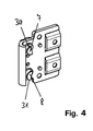
- Fig. 4 the fixed frame side pivot bearing part 1 is shown with a plan view of the back.
- the locking portions 7, 8 and thus the locking elements 5, 6 are in the position of use.
- This means that the bearing axis 24, not shown in FIG. 4 is clamped between the fixing portion 4 and the locking portions 7, 8, wherein the rear engagement portions 30, 31 engage behind the bearing axis 24.
Landscapes
- Engineering & Computer Science (AREA)
- Mechanical Engineering (AREA)
- Hinges (AREA)
- Wing Frames And Configurations (AREA)
- Refrigerator Housings (AREA)
- Securing Of Glass Panes Or The Like (AREA)
- Window Of Vehicle (AREA)
Abstract
Description
- Die Erfindung betrifft ein Fenster, eine Tür oder dergleichen mit einem festen Rahmen sowie einem gegenüber dem festen Rahmen um eine Schwenkachse schwenkbaren Flügel, wobei der Flügel und der feste Rahmen über wenigstens ein Schwenklager miteinander verbunden sind und das Schwenklager ein festrahmenseitiges Schwenklagerteil, ein flügelseitiges Schwenklagerteil sowie eine das festrahmenseitige und das flügelrahmenseitige Schwenklagerteil miteinander verbindende und die Schwenkachse definierende Lagerachse aufweist, wobei ein Fixierabschnitt und zumindest ein Verriegelungselement vorgesehen sind und das Verriegelungselement in eine Gebrauchs- oder Montagestellung überführbar ist, wobei die Verbindung zwischen dem festrahmenseitigen Schwenklagerteil und dem flügelseitigen Schwenklagerteil durch Einschluss der Lagerachse zwischen den Fixierabschnitt und das zumindest eine Verriegelungselement in der Gebrauchsstellung hergestellt ist.
- Bei bekannten Schwenklagern ist der verriegelnde Abschnitt des Verriegelungselements häufig nicht sichtbar. Somit ist es schwierig festzustellen, ob das Verriegelungselement sich in einer Gebrauchsstellung oder in einer Montagestellung befindet. Außerdem sind Verriegelungselemente des Standes der Technik häufig nicht gegen unbeabsichtigtes Lösen des Verriegelungselements gesichert.
- Aufgabe der vorliegenden Erfindung ist es deshalb, den Stand der Technik dahingehend weiterzubilden, dass die Montage- und Gebrauchsstellung des Verriegelungselements klar unterscheidbar sind und die Montage vereinfacht wird.
- Gelöst wird diese Aufgabe durch ein Fenster oder eine Tür der eingangs genannten Art, wobei eine die Stellung des Verriegelungselements anzeigende Stellungsanzeige vorgesehen ist. Somit kann ein Benutzer ohne weiteres feststellen, ob sich das Verriegelungselement in einer Gebrauchsstellung oder in einer Montagestellung befindet. Dabei kann ein Betätigungsabschnitt als Stellungsanzeige ausgebildet sein. Beispielsweise kann der Betätigungsabschnitt bezüglich eines Drehpunktes des Verriegelungselements exzentrisch angeordnet sein. Das Verriegelungselement kann daher so ausgeführt werden, dass eine Verriegelungsstellung für einen Monteur auch von der der Lagerachse abgewandten Seite eines Schwenklagerteils erkennbar ist. Die Vorteile der Erfindung kommen insbesondere auch bei Fenstern oder Türen mit verdeckt liegenden Beschlägen zum Tragen, bei denen ein Flügelüberschlag vorgesehen ist, der einen festen Rahmen überlappt und somit häufig auch das Schwenklager verdeckt. Der Flügel kann ohne Werkzeug (Inbusschlüssel) und Zusatzteil (Achsstift) in das Rahmenlager eingehängt werden. Beim Verriegeln muss der Monteur nicht mehr das Gewicht des Flügels halten und kann den Flügel ohne Hilfe einer zusätzlichen Person montieren.
- Eine Ausführungsform der Erfindung zeichnet sich dadurch aus, dass das Verriegelungselement in der Gebrauchsstellung arretierbar ist. Durch diese Maßnahme kann ein unbeabsichtigtes Lösen des Verriegelungselements verhindert werden. Vorteilhafterweise kann die Stellungsanzeige zur Arretierung verwendet werden.
- Besonders bevorzugt ist es, wenn das Verriegelungselement in der Gebrauchsstellung verrastbar ist. Eine Rastverbindung lässt sich auf besonders einfache Art und Weise realisieren und herstellen. Insbesondere ist zum Herstellen einer Rastverbindung kein zusätzliches Werkzeug notwendig. Durch eine Verrastung wird eine Blockierung des Verriegelungselements in der Gebrauchsstellung bewirkt.
- In vorteilhafter Ausgestaltung der Erfindung kann an dem Schwenklagerteil, an dem das Verriegelungselement angeordnet ist, ein Rastelement und an dem Verriegelungselement eine damit zusammenwirkende Ausnehmung vorgesehen sein. Das Rastelement kann dabei beispielsweise als von dem Schwenklagerteil abstehender Rastbuckel ausgebildet sein. Die Ausnehmung kann als Vertiefung oder Durchgangsöffnung an dem Verriegelungselement ausgebildet sein.
- Besonders bevorzugt ist es, wenn das Verriegelungselement einen Betätigungsabschnitt umfasst, an dem die Ausnehmung angeordnet ist. Dies bedeutet, dass durch Betätigung des Betätigungsabschnittes das Verriegelungselement von einer Montagestellung in eine Gebrauchsstellung überführt werden kann und gleichzeitig die Arretierung des Verriegelungselements in der Gebrauchsstellung hergestellt werden kann. Der Betätigungsabschnitt zeigt vorteilhafterweise in der arretierten Position durch seine Stellung außerdem die Gebrauchsstellung des Verriegelungselements an.
- Bei einer besonders bevorzugten Ausgestaltung kann vorgesehen sein, dass die Ausnehmung eine Durchbruchsöffnung ist, die als Werkzeugeingriff ausgebildet ist. Vorzugsweise ist die Durchbruchsöffnung an dem Betätigungsabschnitt ausgebildet. Die Durchbruchsöffnung kann beispielsweise als Innensechskant ausgebildet sein, so dass der Betätigungsabschnitt mit einem Inbusschlüssel betätigt werden kann.
- Besonders bevorzugt ist es, wenn an dem Betätigungsabschnitt eine zweite Ausnehmung vorgesehen ist, die mit dem Rastelement in der Montagestellung in Eingriff steht. Durch diese Maßnahme ist es möglich, das Verriegelungselement über den Betätigungsabschnitt auch in einer Montagestellung zu arretieren. Somit ist es möglich, das Verriegelungselement bereits werksseitig vorzupositionieren. Durch die Verrastung des Betätigungsabschnitts mit dem Rastelement wird verhindert, dass vor der Montage versehentlich das Verriegelungselement in eine Gebrauchsstellung überführt wird. Außerdem wird durch den Betätigungsabschnitt die Montagestellung des Verriegelungselements angezeigt.
- In bevorzugter Ausgestaltung ist die zweite Ausnehmung kerbenartig an einem Rand des Betätigungsabschnitts ausgebildet.
- Bei einer Ausführungsform der Erfindung kann vorgesehen sein, dass das Verriegelungselement ein Schwenklagerteil durchgreift und bezüglich des Schwenklagerteils verdrehbar ist. Durch diese Maßnahme ist es besonders einfach möglich, das Verriegelungselement von einer Montagestellung in eine Gebrauchsstellung zu überführen. Insbesondere kann das Verriegelungselement durch ein an der der Lagerachse abgewandten Seite angeordnetes Betätigungselement betätigt werden, um einen Verriegelungs abschnitt des Verriegelungselements in eine Stellung zu bringen, in der der Verriegelungsabschnitt die Lagerachse gegenüber dem Fixierabschnitt fixiert.
- Besonders vorteilhaft ist es, wenn das Verriegelungselement einen die Lagerachse in einer Gebrauchsstellung hintergreifenden Hintergreifabschnitt aufweist. Durch diese Maßnahme wird die Lagerachse sicher zwischen dem Fixierabschnitt und dem Verriegelungselement eingeklemmt. Besonders vorteilhaft ist es, wenn zwei Verriegelungselemente vorgesehen sind.
- In den Rahmen der Erfindung fällt auch ein Schwenklager gemäß Patentanspruch 11.
- Nachfolgend wird die Erfindung anhand schematischer Darstellungen zu einem Ausführungsbeispiel näher erläutert. Es zeigen:
- Fig. la
- eine perspektivische Draufsicht auf ein festrahmenseitiges Schwenklagerteil, bei dem sich die Verriegelungselemente in einer Montagestellung befinden;
- Fig. 1b
- ein flügelseitiges Schwenklagerteil mit einer Lagerachse;
- Fig. 2
- eine perspektivische Ansicht eines Schwenklagers in einer Montagestellung der Verriegelungselemente;
- Fig. 3
- eine perspektivische Draufsicht auf ein Schwenklager, bei dem sich die Verriegelungselemente in einer Gebrauchsstellung befinden;
- Fig. 4
- eine Ansicht der Rückseite eines festrahmenseitigen Schwenklagerteils, bei dem sich die Verriegelungselemente in einer Gebrauchsstellung befinden.
- In der Fig. 1a ist ein festrahmenseitiges Schwenklagerteil 1 dargestellt. Das festrahmenseitige Schwenklagerteil 1 umfasst eine Montageplatte 2, in der mehrere Montagebohrungen 3 zur Befestigung an einem festen Rahmen vorgesehen sind. Es ist ein gekrümmter Fixierabschnitt 4 vorgesehen, der in einer Gebrauchsstellung eine Lagerachse teilweise umgreift. Verriegelungselemente 5, 6 werden durch Verriegelungsabschnitte 7, 8 und Betätigungsabschnitte 9, 10 gebildet. Die verriegelungsabschnitte 7, 8 durchgreifen die Montageplatte 2. Die Betätigungsabschnitte 9, 10 sind bezüglich der Verriegelungsabschnitte 7, 8 exzentrisch angeordnet. Sie weisen als Durchgangsöffnungen ausgebildete Ausnehmungen 11, 12 auf, die gleichzeitig als Werkzeugeingriff für einen Inbusschlüssel ausgebildet sind. An den Rändern 13, 14 weisen die Betätigungsabschnitte 9, 10 jeweils eine zweite Ausnehmung 15, 16 auf, die mit einem als Rastbuckel ausgebildeten Rastelement 17, 18 in der gezeigten Montagestellung in Eingriff stehen und dadurch in dieser Stellung fixiert sind. Durch die gezeigte Stellung der Betätigungsabschnitte 9, 10 wird die Montagestellung der Verriegelungsabschnitte 7, 8 angezeigt. Die Betätigungsabschnitte 9, 10 stellen also eine Stellungsanzeige dar.
- In der Fig. 1b ist ein flügelseitiges Schwenklagerteil 20 dargestellt, welches an einem flügelseitigen Achsträger 21 angeordnet ist. Das Schwenklagerteil 20 weist lappenartige Lagervorsprünge 22, 23 auf, zwischen denen eine Lagerachse 24 angeordnet ist. Die Lagerachse 24 durchgreift die lappenartigen Lagervorsprünge 22, 23 und ist bezüglich der Lagervorsprünge 22, 23 verdrehbar angeordnet.
- Die Schwenklagerteile 1, 20 bilden ein Schwenklager 29, das insbesondere bei einem verdeckt liegenden Dreh- bzw. Drehkippbeschlag zum Einsatz kommen kann.
- In der Fig. 2 wird gezeigt, wie das flügelseitige Schwenklagerteil 20 mit der Lagerachse 24 in den Fixierabschnitt 4 eingehängt wird. Die Lagerachse 24 liegt dabei nahezu über ihre gesamte Länge am Fixierabschnitt 4 an. In der Fig. 2 sind außerdem die der Lagerachse 24 zugewandten Enden der Verriegelungsabschnitte 7, 8 gezeigt. Die Verriegelungsabschnitte 7, 8 weisen Hintergreifabschnitte 30, 31 auf, mit denen die Lagerachse 24 hintergriffen werden kann und damit zwischen den Verriegelungsabschnitten 7, 8 und dem Fixierabschnitt 4 eingespannt werden kann. In der Fig. 2 ist jedoch die nicht verriegelte Stellung, d.h. die Montagestellung der Verriegelungsabschnitte 7, 8 dargestellt. Die Enden der Verriegelungsabschnitte 7, 8 weisen eine in etwa halbkreisförmige Gestalt auf, so dass in der Montagestellung ein genügend großer Spalt freigegeben wird, über den die Lagerachse 24 zwischen die Fixiereinrichtung 4 und die Verriegelungsabschnitte 7, 8 eingeführt werden kann.
- In der Fig. 3 ist das Schwenklager 29 in einer anderen Perspektive und mit sich in einer Gebrauchsstellung befindenden Verriegelungselementen 5, 6 dargestellt. Die Gebrauchsstellung ist daran zu erkennen, dass die Betätigungsabschnitte 9, 10 um nahezu 180 Grad verschwenkt wurden. Die Ausnehmungen 11, 12 sind nun benachbart zueinander angeordnet und liegen über den in der Fig. 1a dargestellten Rastelementen 17, 18. Dies bedeutet, dass die Betätigungsabschnitte 9, 10 und damit die Verriegelungselemente 5, 6 in ihrer Gebrauchsstellung arretiert sind. Sie sind über die Ausnehmungen 11, 12 mit den Rastelementen 17, 18 verrastet.
- In der Fig. 4 ist das festrahmenseitige Schwenklagerteil 1 mit einer Draufsicht auf die Rückseite dargestellt. Die Verriegelungsabschnitte 7, 8 und damit die Verriegelungselemente 5, 6 befinden sich in der Gebrauchsstellung. Dies bedeutet, dass die in der Fig. 4 nicht dargestellte Lagerachse 24 zwischen den Fixierabschnitt 4 und die Verriegelungsabschnitte 7, 8 eingeklemmt ist, wobei die Hintergreifabschnitte 30, 31 die Lagerachse 24 hintergreifen. Durch die Lagefixierung bzw. Drehsicherung der Verriegelungselemente 5, 6 in der Gebrauchsstellung wird ein unbeabsichtigtes Lösen der Verriegelung, d.h. Überführen der Verriegelungsabschnitte 7, 8 in eine Montagestellung, verhindert.
Claims (11)
- Fenster, Tür oder dergleichen mit einem festen Rahmen sowie einem gegenüber dem festen Rahmen um eine Schwenkachse schwenkbaren Flügel, wobei der Flügel und der feste Rahmen über wenigstens ein Schwenklager (29) miteinander verbunden sind und das Schwenklager (29) ein festrahmenseitiges Schwenklagerteil (1), ein flügelseitiges Schwenklagerteil (20) sowie eine das festrahmenseitige und das flügelrahmenseitige Schwenklagerteil (1, 20) miteinander verbindende und die Schwenkachse definierende Lagerachse (24) aufweist, wobei ein Fixierabschnitt (4) und zumindest ein Verriegelungselement (5, 6) vorgesehen sind und das Verriegelungselement (5, 6) in eine Gebrauchs- oder Montagestellung überführbar ist, wobei die Verbindung zwischen dem festrahmenseitigen Schwenklagerteil (1) und dem flügelseitigen Schwenklagerteil (20) durch Einschluss der Lagerachse (24) zwischen den Fixierabschnitt (4) und das zumindest eine Verriegelungselement (5, 6) in der Gebrauchsstellung hergestellt ist, dadurch gekennzeichnet, dass eine die Stellung des Verriegelungselements (5, 6) anzeigende Stellungsanzeige vorgesehen ist.
- Fenster, Tür oder dergleichen nach Anspruch 1, dadurch gekennzeichnet, dass das Verriegelungselement (5, 6) in der Gebrauchsstellung arretierbar ist.
- Fenster, Tür oder dergleichen nach einem der vorhergehenden Ansprüche, dadurch gekennzeichnet, dass das Verriegelungselement (5, 6) in der Gebrauchsstellung verrastbar ist.
- Fenster, Tür oder dergleichen nach einem der vorhergehenden Ansprüche, dadurch gekennzeichnet, dass an dem Schwenklagerteil (1, 20), an dem das Verriegelungselement (5, 6) angeordnet ist, ein Rastelement (17, 18) vorgesehen ist und an dem Verriegelungselement (5, 6) eine damit zusammen wirkende Ausnehmung (11, 12) vorgesehen ist.
- Fenster, Tür oder dergleichen nach einem der vorhergehenden Ansprüche, dadurch gekennzeichnet, dass das Verriegelungselement (5, 6) einen Betätigungsabschnitt (9, 10) umfasst, an dem die Ausnehmung (11, 12) angeordnet ist.
- Fenster, Tür oder dergleichen, nach einem der vorhergehenden Ansprüche, dadurch gekennzeichnet, dass die Ausnehmung (11, 12) eine Durchbruchsöffnung ist, die als Werkzeugeingriff ausgebildet ist.
- Fenster, Tür oder dergleichen nach einem der vorhergehenden Ansprüche, dadurch gekennzeichnet, dass an dem Betätigungsabschnitt (9, 10) eine zweite Ausnehmung (15, 16) vorgesehen ist, die mit dem Rastelement (17, 18) in der Montagestellung in Eingriff steht.
- Fenster, Tür oder dergleichen, dadurch gekennzeichnet, dass die zweite Ausnehmung (15, 16) kerbenartig an einem Rand (13, 14) des Betätigungsabschnitts (9, 10) ausgebildet ist.
- Fenster, Tür oder dergleichen nach einem der vorhergehenden Ansprüche, dadurch gekennzeichnet, dass das Verriegelungselement (5, 6) ein Schwenklagerteil (1, 20) durchgreift und bezüglich des Schwenklagerteils (1, 20) verdrehbar ist.
- Fenster, Tür oder dergleichen nach einem der vorhergehenden Ansprüche, dadurch gekennzeichnet, dass das Verriegelungselement (5, 6) einen die Lagerachse (24) in einer Gebrauchsstellung hintergreifenden Hintergreifabschnitt (30, 31) aufweist.
- Schwenklager (29) für ein Fenster, eine Tür oder dergleichen, gekennzeichnet durch die Schwenklagermerkmale wenigstens eines der vorhergehenden Ansprüche.
Priority Applications (1)
| Application Number | Priority Date | Filing Date | Title |
|---|---|---|---|
| PL05022562T PL1657390T3 (pl) | 2004-11-13 | 2005-10-17 | Okno, drzwi lub tym podobne z łożyskiem wychylnym |
Applications Claiming Priority (1)
| Application Number | Priority Date | Filing Date | Title |
|---|---|---|---|
| DE202004017659U DE202004017659U1 (de) | 2004-11-13 | 2004-11-13 | Fenster, Tür o.dgl. mit einem Schwenklager |
Publications (3)
| Publication Number | Publication Date |
|---|---|
| EP1657390A2 true EP1657390A2 (de) | 2006-05-17 |
| EP1657390A3 EP1657390A3 (de) | 2010-11-24 |
| EP1657390B1 EP1657390B1 (de) | 2012-02-01 |
Family
ID=34223756
Family Applications (1)
| Application Number | Title | Priority Date | Filing Date |
|---|---|---|---|
| EP05022562A Expired - Lifetime EP1657390B1 (de) | 2004-11-13 | 2005-10-17 | Fenster, Tür oder dergleichen mit einem Schwenklager |
Country Status (4)
| Country | Link |
|---|---|
| EP (1) | EP1657390B1 (de) |
| AT (1) | ATE543974T1 (de) |
| DE (1) | DE202004017659U1 (de) |
| PL (1) | PL1657390T3 (de) |
Cited By (1)
| Publication number | Priority date | Publication date | Assignee | Title |
|---|---|---|---|---|
| WO2016066779A1 (en) * | 2014-10-31 | 2016-05-06 | Tyco Electronics Raychem Bvba | Hinge lock device and method |
Citations (2)
| Publication number | Priority date | Publication date | Assignee | Title |
|---|---|---|---|---|
| DE9306248U1 (de) | 1993-01-05 | 1993-07-08 | Kodak Ag, 7000 Stuttgart | Scharnier |
| EP0887502A1 (de) | 1997-06-24 | 1998-12-30 | Sirandre Societe Anonyme | Vorrichtung zum Montieren einer Tür an einem Rahmen |
-
2004
- 2004-11-13 DE DE202004017659U patent/DE202004017659U1/de not_active Expired - Lifetime
-
2005
- 2005-10-17 PL PL05022562T patent/PL1657390T3/pl unknown
- 2005-10-17 AT AT05022562T patent/ATE543974T1/de active
- 2005-10-17 EP EP05022562A patent/EP1657390B1/de not_active Expired - Lifetime
Patent Citations (2)
| Publication number | Priority date | Publication date | Assignee | Title |
|---|---|---|---|---|
| DE9306248U1 (de) | 1993-01-05 | 1993-07-08 | Kodak Ag, 7000 Stuttgart | Scharnier |
| EP0887502A1 (de) | 1997-06-24 | 1998-12-30 | Sirandre Societe Anonyme | Vorrichtung zum Montieren einer Tür an einem Rahmen |
Cited By (1)
| Publication number | Priority date | Publication date | Assignee | Title |
|---|---|---|---|---|
| WO2016066779A1 (en) * | 2014-10-31 | 2016-05-06 | Tyco Electronics Raychem Bvba | Hinge lock device and method |
Also Published As
| Publication number | Publication date |
|---|---|
| PL1657390T3 (pl) | 2012-07-31 |
| EP1657390A3 (de) | 2010-11-24 |
| EP1657390B1 (de) | 2012-02-01 |
| ATE543974T1 (de) | 2012-02-15 |
| DE202004017659U1 (de) | 2005-02-24 |
Similar Documents
| Publication | Publication Date | Title |
|---|---|---|
| EP3918165B1 (de) | Klappenbeschlag für ein möbel | |
| DE102007017453B4 (de) | Drehöffnungsbegrenzungsvorrichtung für einen Flügel eines Fensters oder dergleichen | |
| DE69805903T2 (de) | Beschlag mit einstellbarem Riegel für Schiebeflügel | |
| EP0947654A1 (de) | Verschwindscharnier | |
| EP2947221B1 (de) | Dachfenster sowie verfahren zum montieren eines dachfensters | |
| EP1657390B1 (de) | Fenster, Tür oder dergleichen mit einem Schwenklager | |
| EP4105416B1 (de) | Feststellvorrichtung für beidseitig angeschlagene tür | |
| EP1709268B1 (de) | Stangenschloss zur montage in einem durchbruch in einer dünnen wand (indirekte klipsbefestigung) | |
| EP3187671A1 (de) | Verriegelungsvorrichtung als einbruchssicherung für z. b. fenster und türen | |
| DE102015120712A1 (de) | Fenster zum Verschließen einer Gebäudeöffnung | |
| EP1837460B1 (de) | Beschlag für einen Schiebeflügel sowie Beschlagsystem | |
| EP3553260B1 (de) | Falleneinsatz mit tagstellung zur bedingten freigabe einer schlossfalle eines türschlossmechanismus | |
| EP4045744B1 (de) | Beschlaganordnung | |
| DE102014007699B3 (de) | Schwingscharnier für ein Fenster, insbesondere Wohndachfenster | |
| DE102014111131A1 (de) | Vorrichtung zur Ver- und Entriegelung eines Fensterflügels, einer Lüftungsklappe oder dergleichen an einem Blendrahmen | |
| DE102012104863B3 (de) | Türbandanordnung mit einem Türband und einem Aufnahmeelement | |
| EP3441547B1 (de) | Schliessblech für einen treibstangenbeschlag | |
| EP3095938B1 (de) | Beschlag sowie verfahren zum herstellen eines beschlags | |
| DE102016004915B3 (de) | Beschlag für ein Fenster, Verfahren zum Herstellen des Beschlags sowie entsprechendes Fenster | |
| EP1559856B1 (de) | Fenster, Tür oder dergleichen mit einem Stulpschienenbeschlag | |
| EP0913546B1 (de) | Getriebebeschlag für einen Flügelrahmen | |
| DE202007010048U1 (de) | Fenster, Tür o.dgl. mit einem Schließstück | |
| DE202019004779U1 (de) | Sicherheitseinrichtung | |
| DE102019209409A1 (de) | Abdeckhaube für einen tür- oder fensterantrieb | |
| CH716231B1 (de) | Scharnier. |
Legal Events
| Date | Code | Title | Description |
|---|---|---|---|
| PUAI | Public reference made under article 153(3) epc to a published international application that has entered the european phase |
Free format text: ORIGINAL CODE: 0009012 |
|
| AK | Designated contracting states |
Kind code of ref document: A2 Designated state(s): AT BE BG CH CY CZ DE DK EE ES FI FR GB GR HU IE IS IT LI LT LU LV MC NL PL PT RO SE SI SK TR |
|
| AX | Request for extension of the european patent |
Extension state: AL BA HR MK YU |
|
| PUAL | Search report despatched |
Free format text: ORIGINAL CODE: 0009013 |
|
| AK | Designated contracting states |
Kind code of ref document: A3 Designated state(s): AT BE BG CH CY CZ DE DK EE ES FI FR GB GR HU IE IS IT LI LT LU LV MC NL PL PT RO SE SI SK TR |
|
| AX | Request for extension of the european patent |
Extension state: AL BA HR MK YU |
|
| GRAP | Despatch of communication of intention to grant a patent |
Free format text: ORIGINAL CODE: EPIDOSNIGR1 |
|
| 17P | Request for examination filed |
Effective date: 20110510 |
|
| RIC1 | Information provided on ipc code assigned before grant |
Ipc: E05D 7/10 20060101AFI20110607BHEP |
|
| AKX | Designation fees paid |
Designated state(s): AT BE BG CH CY CZ DE DK EE ES FI FR GB GR HU IE IS IT LI LT LU LV MC NL PL PT RO SE SI SK TR |
|
| GRAS | Grant fee paid |
Free format text: ORIGINAL CODE: EPIDOSNIGR3 |
|
| GRAA | (expected) grant |
Free format text: ORIGINAL CODE: 0009210 |
|
| 17Q | First examination report despatched |
Effective date: 20111202 |
|
| AK | Designated contracting states |
Kind code of ref document: B1 Designated state(s): AT BE BG CH CY CZ DE DK EE ES FI FR GB GR HU IE IS IT LI LT LU LV MC NL PL PT RO SE SI SK TR |
|
| REG | Reference to a national code |
Ref country code: GB Ref legal event code: FG4D Free format text: NOT ENGLISH |
|
| REG | Reference to a national code |
Ref country code: DE Ref legal event code: R081 Ref document number: 502005012407 Country of ref document: DE Owner name: ROTO FRANK AKTIENGESELLSCHAFT, DE Free format text: FORMER OWNER: ROTO FRANK AG, 70771 LEINFELDEN-ECHTERDINGEN, DE |
|
| REG | Reference to a national code |
Ref country code: CH Ref legal event code: EP Ref country code: AT Ref legal event code: REF Ref document number: 543974 Country of ref document: AT Kind code of ref document: T Effective date: 20120215 |
|
| REG | Reference to a national code |
Ref country code: DE Ref legal event code: R096 Ref document number: 502005012407 Country of ref document: DE Effective date: 20120329 |
|
| REG | Reference to a national code |
Ref country code: NL Ref legal event code: VDEP Effective date: 20120201 |
|
| LTIE | Lt: invalidation of european patent or patent extension |
Effective date: 20120201 |
|
| PG25 | Lapsed in a contracting state [announced via postgrant information from national office to epo] |
Ref country code: IS Free format text: LAPSE BECAUSE OF FAILURE TO SUBMIT A TRANSLATION OF THE DESCRIPTION OR TO PAY THE FEE WITHIN THE PRESCRIBED TIME-LIMIT Effective date: 20120601 Ref country code: LT Free format text: LAPSE BECAUSE OF FAILURE TO SUBMIT A TRANSLATION OF THE DESCRIPTION OR TO PAY THE FEE WITHIN THE PRESCRIBED TIME-LIMIT Effective date: 20120201 Ref country code: NL Free format text: LAPSE BECAUSE OF FAILURE TO SUBMIT A TRANSLATION OF THE DESCRIPTION OR TO PAY THE FEE WITHIN THE PRESCRIBED TIME-LIMIT Effective date: 20120201 |
|
| REG | Reference to a national code |
Ref country code: PL Ref legal event code: T3 |
|
| REG | Reference to a national code |
Ref country code: IE Ref legal event code: FD4D |
|
| PG25 | Lapsed in a contracting state [announced via postgrant information from national office to epo] |
Ref country code: GR Free format text: LAPSE BECAUSE OF FAILURE TO SUBMIT A TRANSLATION OF THE DESCRIPTION OR TO PAY THE FEE WITHIN THE PRESCRIBED TIME-LIMIT Effective date: 20120502 Ref country code: LV Free format text: LAPSE BECAUSE OF FAILURE TO SUBMIT A TRANSLATION OF THE DESCRIPTION OR TO PAY THE FEE WITHIN THE PRESCRIBED TIME-LIMIT Effective date: 20120201 Ref country code: FI Free format text: LAPSE BECAUSE OF FAILURE TO SUBMIT A TRANSLATION OF THE DESCRIPTION OR TO PAY THE FEE WITHIN THE PRESCRIBED TIME-LIMIT Effective date: 20120201 Ref country code: PT Free format text: LAPSE BECAUSE OF FAILURE TO SUBMIT A TRANSLATION OF THE DESCRIPTION OR TO PAY THE FEE WITHIN THE PRESCRIBED TIME-LIMIT Effective date: 20120601 |
|
| PG25 | Lapsed in a contracting state [announced via postgrant information from national office to epo] |
Ref country code: CY Free format text: LAPSE BECAUSE OF FAILURE TO SUBMIT A TRANSLATION OF THE DESCRIPTION OR TO PAY THE FEE WITHIN THE PRESCRIBED TIME-LIMIT Effective date: 20120201 |
|
| PG25 | Lapsed in a contracting state [announced via postgrant information from national office to epo] |
Ref country code: DK Free format text: LAPSE BECAUSE OF FAILURE TO SUBMIT A TRANSLATION OF THE DESCRIPTION OR TO PAY THE FEE WITHIN THE PRESCRIBED TIME-LIMIT Effective date: 20120201 Ref country code: SE Free format text: LAPSE BECAUSE OF FAILURE TO SUBMIT A TRANSLATION OF THE DESCRIPTION OR TO PAY THE FEE WITHIN THE PRESCRIBED TIME-LIMIT Effective date: 20120201 Ref country code: SI Free format text: LAPSE BECAUSE OF FAILURE TO SUBMIT A TRANSLATION OF THE DESCRIPTION OR TO PAY THE FEE WITHIN THE PRESCRIBED TIME-LIMIT Effective date: 20120201 Ref country code: RO Free format text: LAPSE BECAUSE OF FAILURE TO SUBMIT A TRANSLATION OF THE DESCRIPTION OR TO PAY THE FEE WITHIN THE PRESCRIBED TIME-LIMIT Effective date: 20120201 Ref country code: EE Free format text: LAPSE BECAUSE OF FAILURE TO SUBMIT A TRANSLATION OF THE DESCRIPTION OR TO PAY THE FEE WITHIN THE PRESCRIBED TIME-LIMIT Effective date: 20120201 Ref country code: IE Free format text: LAPSE BECAUSE OF FAILURE TO SUBMIT A TRANSLATION OF THE DESCRIPTION OR TO PAY THE FEE WITHIN THE PRESCRIBED TIME-LIMIT Effective date: 20120201 |
|
| PG25 | Lapsed in a contracting state [announced via postgrant information from national office to epo] |
Ref country code: IT Free format text: LAPSE BECAUSE OF FAILURE TO SUBMIT A TRANSLATION OF THE DESCRIPTION OR TO PAY THE FEE WITHIN THE PRESCRIBED TIME-LIMIT Effective date: 20120201 Ref country code: SK Free format text: LAPSE BECAUSE OF FAILURE TO SUBMIT A TRANSLATION OF THE DESCRIPTION OR TO PAY THE FEE WITHIN THE PRESCRIBED TIME-LIMIT Effective date: 20120201 |
|
| PLBE | No opposition filed within time limit |
Free format text: ORIGINAL CODE: 0009261 |
|
| STAA | Information on the status of an ep patent application or granted ep patent |
Free format text: STATUS: NO OPPOSITION FILED WITHIN TIME LIMIT |
|
| 26N | No opposition filed |
Effective date: 20121105 |
|
| REG | Reference to a national code |
Ref country code: DE Ref legal event code: R097 Ref document number: 502005012407 Country of ref document: DE Effective date: 20121105 |
|
| BERE | Be: lapsed |
Owner name: ROTO FRANK A.G. Effective date: 20121031 |
|
| PG25 | Lapsed in a contracting state [announced via postgrant information from national office to epo] |
Ref country code: ES Free format text: LAPSE BECAUSE OF FAILURE TO SUBMIT A TRANSLATION OF THE DESCRIPTION OR TO PAY THE FEE WITHIN THE PRESCRIBED TIME-LIMIT Effective date: 20120512 |
|
| PG25 | Lapsed in a contracting state [announced via postgrant information from national office to epo] |
Ref country code: MC Free format text: LAPSE BECAUSE OF NON-PAYMENT OF DUE FEES Effective date: 20121031 |
|
| PG25 | Lapsed in a contracting state [announced via postgrant information from national office to epo] |
Ref country code: BE Free format text: LAPSE BECAUSE OF NON-PAYMENT OF DUE FEES Effective date: 20121031 Ref country code: BG Free format text: LAPSE BECAUSE OF FAILURE TO SUBMIT A TRANSLATION OF THE DESCRIPTION OR TO PAY THE FEE WITHIN THE PRESCRIBED TIME-LIMIT Effective date: 20120501 |
|
| PGFP | Annual fee paid to national office [announced via postgrant information from national office to epo] |
Ref country code: AT Payment date: 20131021 Year of fee payment: 9 Ref country code: CZ Payment date: 20131010 Year of fee payment: 9 Ref country code: CH Payment date: 20131023 Year of fee payment: 9 Ref country code: GB Payment date: 20131022 Year of fee payment: 9 Ref country code: FR Payment date: 20131018 Year of fee payment: 9 |
|
| PG25 | Lapsed in a contracting state [announced via postgrant information from national office to epo] |
Ref country code: TR Free format text: LAPSE BECAUSE OF FAILURE TO SUBMIT A TRANSLATION OF THE DESCRIPTION OR TO PAY THE FEE WITHIN THE PRESCRIBED TIME-LIMIT Effective date: 20120201 |
|
| PG25 | Lapsed in a contracting state [announced via postgrant information from national office to epo] |
Ref country code: LU Free format text: LAPSE BECAUSE OF NON-PAYMENT OF DUE FEES Effective date: 20121017 |
|
| PG25 | Lapsed in a contracting state [announced via postgrant information from national office to epo] |
Ref country code: HU Free format text: LAPSE BECAUSE OF FAILURE TO SUBMIT A TRANSLATION OF THE DESCRIPTION OR TO PAY THE FEE WITHIN THE PRESCRIBED TIME-LIMIT Effective date: 20051017 |
|
| PGFP | Annual fee paid to national office [announced via postgrant information from national office to epo] |
Ref country code: PL Payment date: 20140826 Year of fee payment: 10 |
|
| REG | Reference to a national code |
Ref country code: CH Ref legal event code: PL |
|
| REG | Reference to a national code |
Ref country code: AT Ref legal event code: MM01 Ref document number: 543974 Country of ref document: AT Kind code of ref document: T Effective date: 20141017 |
|
| GBPC | Gb: european patent ceased through non-payment of renewal fee |
Effective date: 20141017 |
|
| PG25 | Lapsed in a contracting state [announced via postgrant information from national office to epo] |
Ref country code: GB Free format text: LAPSE BECAUSE OF NON-PAYMENT OF DUE FEES Effective date: 20141017 Ref country code: LI Free format text: LAPSE BECAUSE OF NON-PAYMENT OF DUE FEES Effective date: 20141031 Ref country code: CH Free format text: LAPSE BECAUSE OF NON-PAYMENT OF DUE FEES Effective date: 20141031 Ref country code: CZ Free format text: LAPSE BECAUSE OF NON-PAYMENT OF DUE FEES Effective date: 20141017 |
|
| REG | Reference to a national code |
Ref country code: FR Ref legal event code: ST Effective date: 20150630 |
|
| PG25 | Lapsed in a contracting state [announced via postgrant information from national office to epo] |
Ref country code: AT Free format text: LAPSE BECAUSE OF NON-PAYMENT OF DUE FEES Effective date: 20141017 Ref country code: FR Free format text: LAPSE BECAUSE OF NON-PAYMENT OF DUE FEES Effective date: 20141031 |
|
| REG | Reference to a national code |
Ref country code: DE Ref legal event code: R084 Ref document number: 502005012407 Country of ref document: DE |
|
| REG | Reference to a national code |
Ref country code: DE Ref legal event code: R082 Ref document number: 502005012407 Country of ref document: DE Representative=s name: KOHLER SCHMID MOEBUS PATENTANWAELTE PARTNERSCH, DE Ref country code: DE Ref legal event code: R081 Ref document number: 502005012407 Country of ref document: DE Owner name: ROTO FRANK AKTIENGESELLSCHAFT, DE Free format text: FORMER OWNER: ROTO FRANK AG, 70771 LEINFELDEN-ECHTERDINGEN, DE |
|
| PGFP | Annual fee paid to national office [announced via postgrant information from national office to epo] |
Ref country code: DE Payment date: 20151028 Year of fee payment: 11 |
|
| PG25 | Lapsed in a contracting state [announced via postgrant information from national office to epo] |
Ref country code: PL Free format text: LAPSE BECAUSE OF NON-PAYMENT OF DUE FEES Effective date: 20151017 |
|
| REG | Reference to a national code |
Ref country code: DE Ref legal event code: R119 Ref document number: 502005012407 Country of ref document: DE |
|
| PG25 | Lapsed in a contracting state [announced via postgrant information from national office to epo] |
Ref country code: DE Free format text: LAPSE BECAUSE OF NON-PAYMENT OF DUE FEES Effective date: 20170503 |