EP1657323A1 - Sliding member with excellent wear resistance in water-based environments - Google Patents
Sliding member with excellent wear resistance in water-based environments Download PDFInfo
- Publication number
- EP1657323A1 EP1657323A1 EP20050023195 EP05023195A EP1657323A1 EP 1657323 A1 EP1657323 A1 EP 1657323A1 EP 20050023195 EP20050023195 EP 20050023195 EP 05023195 A EP05023195 A EP 05023195A EP 1657323 A1 EP1657323 A1 EP 1657323A1
- Authority
- EP
- European Patent Office
- Prior art keywords
- sliding
- dlc
- film
- dlc film
- water
- Prior art date
- Legal status (The legal status is an assumption and is not a legal conclusion. Google has not performed a legal analysis and makes no representation as to the accuracy of the status listed.)
- Granted
Links
- XLYOFNOQVPJJNP-UHFFFAOYSA-N water Substances O XLYOFNOQVPJJNP-UHFFFAOYSA-N 0.000 title claims abstract description 34
- 229910052739 hydrogen Inorganic materials 0.000 claims abstract description 32
- 239000001257 hydrogen Substances 0.000 claims abstract description 32
- UFHFLCQGNIYNRP-UHFFFAOYSA-N Hydrogen Chemical compound [H][H] UFHFLCQGNIYNRP-UHFFFAOYSA-N 0.000 claims abstract description 31
- 229910003481 amorphous carbon Inorganic materials 0.000 claims abstract description 18
- 239000000463 material Substances 0.000 description 24
- 238000012360 testing method Methods 0.000 description 19
- OKTJSMMVPCPJKN-UHFFFAOYSA-N Carbon Chemical compound [C] OKTJSMMVPCPJKN-UHFFFAOYSA-N 0.000 description 15
- 229910052799 carbon Inorganic materials 0.000 description 14
- 238000000034 method Methods 0.000 description 11
- VNWKTOKETHGBQD-UHFFFAOYSA-N methane Chemical compound C VNWKTOKETHGBQD-UHFFFAOYSA-N 0.000 description 9
- 238000000151 deposition Methods 0.000 description 8
- 239000007789 gas Substances 0.000 description 8
- 238000004544 sputter deposition Methods 0.000 description 8
- 230000008021 deposition Effects 0.000 description 6
- 230000008020 evaporation Effects 0.000 description 6
- 238000001704 evaporation Methods 0.000 description 6
- 239000004215 Carbon black (E152) Substances 0.000 description 5
- 229930195733 hydrocarbon Natural products 0.000 description 5
- 239000000919 ceramic Substances 0.000 description 4
- 238000010438 heat treatment Methods 0.000 description 4
- 150000002430 hydrocarbons Chemical class 0.000 description 4
- 238000012546 transfer Methods 0.000 description 4
- 238000000576 coating method Methods 0.000 description 3
- 238000011156 evaluation Methods 0.000 description 3
- 239000007769 metal material Substances 0.000 description 3
- 239000002904 solvent Substances 0.000 description 3
- 239000000758 substrate Substances 0.000 description 3
- LFQSCWFLJHTTHZ-UHFFFAOYSA-N Ethanol Chemical compound CCO LFQSCWFLJHTTHZ-UHFFFAOYSA-N 0.000 description 2
- VGGSQFUCUMXWEO-UHFFFAOYSA-N Ethene Chemical compound C=C VGGSQFUCUMXWEO-UHFFFAOYSA-N 0.000 description 2
- 239000005977 Ethylene Substances 0.000 description 2
- 229910052804 chromium Inorganic materials 0.000 description 2
- 239000011248 coating agent Substances 0.000 description 2
- 239000012153 distilled water Substances 0.000 description 2
- 238000001678 elastic recoil detection analysis Methods 0.000 description 2
- 230000001050 lubricating effect Effects 0.000 description 2
- 238000005461 lubrication Methods 0.000 description 2
- 238000001755 magnetron sputter deposition Methods 0.000 description 2
- 229910052751 metal Inorganic materials 0.000 description 2
- 239000002184 metal Substances 0.000 description 2
- 150000002736 metal compounds Chemical class 0.000 description 2
- 150000004767 nitrides Chemical class 0.000 description 2
- 239000002245 particle Substances 0.000 description 2
- 238000011160 research Methods 0.000 description 2
- 229910052710 silicon Inorganic materials 0.000 description 2
- 229910000838 Al alloy Inorganic materials 0.000 description 1
- 229910000881 Cu alloy Inorganic materials 0.000 description 1
- 229910000640 Fe alloy Inorganic materials 0.000 description 1
- 229910000997 High-speed steel Inorganic materials 0.000 description 1
- 229910001069 Ti alloy Inorganic materials 0.000 description 1
- NRTOMJZYCJJWKI-UHFFFAOYSA-N Titanium nitride Chemical compound [Ti]#N NRTOMJZYCJJWKI-UHFFFAOYSA-N 0.000 description 1
- 229910001315 Tool steel Inorganic materials 0.000 description 1
- 230000002411 adverse Effects 0.000 description 1
- 229910045601 alloy Inorganic materials 0.000 description 1
- 239000000956 alloy Substances 0.000 description 1
- PNEYBMLMFCGWSK-UHFFFAOYSA-N aluminium oxide Inorganic materials [O-2].[O-2].[O-2].[Al+3].[Al+3] PNEYBMLMFCGWSK-UHFFFAOYSA-N 0.000 description 1
- 230000015572 biosynthetic process Effects 0.000 description 1
- 238000006243 chemical reaction Methods 0.000 description 1
- 238000005229 chemical vapour deposition Methods 0.000 description 1
- 230000000052 comparative effect Effects 0.000 description 1
- 238000011109 contamination Methods 0.000 description 1
- 230000003247 decreasing effect Effects 0.000 description 1
- 230000001419 dependent effect Effects 0.000 description 1
- 229910003460 diamond Inorganic materials 0.000 description 1
- 239000010432 diamond Substances 0.000 description 1
- 230000000694 effects Effects 0.000 description 1
- 238000010891 electric arc Methods 0.000 description 1
- 239000000839 emulsion Substances 0.000 description 1
- 229920006351 engineering plastic Polymers 0.000 description 1
- 230000007613 environmental effect Effects 0.000 description 1
- 239000011521 glass Substances 0.000 description 1
- 229910002804 graphite Inorganic materials 0.000 description 1
- 239000010439 graphite Substances 0.000 description 1
- 150000002431 hydrogen Chemical class 0.000 description 1
- 125000004435 hydrogen atom Chemical group [H]* 0.000 description 1
- 150000002484 inorganic compounds Chemical class 0.000 description 1
- 229910010272 inorganic material Inorganic materials 0.000 description 1
- 150000002500 ions Chemical class 0.000 description 1
- 239000000314 lubricant Substances 0.000 description 1
- 229910052750 molybdenum Inorganic materials 0.000 description 1
- HDKLIZDXVUCLHQ-UHFFFAOYSA-N non-3-en-2-one Chemical compound CCCCCC=CC(C)=O HDKLIZDXVUCLHQ-UHFFFAOYSA-N 0.000 description 1
- 239000011224 oxide ceramic Substances 0.000 description 1
- 229910052574 oxide ceramic Inorganic materials 0.000 description 1
- 230000001681 protective effect Effects 0.000 description 1
- 239000002994 raw material Substances 0.000 description 1
- 230000009467 reduction Effects 0.000 description 1
- 239000011347 resin Substances 0.000 description 1
- 229920005989 resin Polymers 0.000 description 1
- 239000007787 solid Substances 0.000 description 1
- 229910001220 stainless steel Inorganic materials 0.000 description 1
- 239000010935 stainless steel Substances 0.000 description 1
- 239000008399 tap water Substances 0.000 description 1
- 235000020679 tap water Nutrition 0.000 description 1
- 239000010936 titanium Substances 0.000 description 1
- 229910052719 titanium Inorganic materials 0.000 description 1
- 229910052721 tungsten Inorganic materials 0.000 description 1
- 238000002604 ultrasonography Methods 0.000 description 1
- 229910052726 zirconium Inorganic materials 0.000 description 1
Images


Classifications
-
- C—CHEMISTRY; METALLURGY
- C23—COATING METALLIC MATERIAL; COATING MATERIAL WITH METALLIC MATERIAL; CHEMICAL SURFACE TREATMENT; DIFFUSION TREATMENT OF METALLIC MATERIAL; COATING BY VACUUM EVAPORATION, BY SPUTTERING, BY ION IMPLANTATION OR BY CHEMICAL VAPOUR DEPOSITION, IN GENERAL; INHIBITING CORROSION OF METALLIC MATERIAL OR INCRUSTATION IN GENERAL
- C23C—COATING METALLIC MATERIAL; COATING MATERIAL WITH METALLIC MATERIAL; SURFACE TREATMENT OF METALLIC MATERIAL BY DIFFUSION INTO THE SURFACE, BY CHEMICAL CONVERSION OR SUBSTITUTION; COATING BY VACUUM EVAPORATION, BY SPUTTERING, BY ION IMPLANTATION OR BY CHEMICAL VAPOUR DEPOSITION, IN GENERAL
- C23C14/00—Coating by vacuum evaporation, by sputtering or by ion implantation of the coating forming material
- C23C14/06—Coating by vacuum evaporation, by sputtering or by ion implantation of the coating forming material characterised by the coating material
- C23C14/0605—Carbon
-
- C—CHEMISTRY; METALLURGY
- C23—COATING METALLIC MATERIAL; COATING MATERIAL WITH METALLIC MATERIAL; CHEMICAL SURFACE TREATMENT; DIFFUSION TREATMENT OF METALLIC MATERIAL; COATING BY VACUUM EVAPORATION, BY SPUTTERING, BY ION IMPLANTATION OR BY CHEMICAL VAPOUR DEPOSITION, IN GENERAL; INHIBITING CORROSION OF METALLIC MATERIAL OR INCRUSTATION IN GENERAL
- C23C—COATING METALLIC MATERIAL; COATING MATERIAL WITH METALLIC MATERIAL; SURFACE TREATMENT OF METALLIC MATERIAL BY DIFFUSION INTO THE SURFACE, BY CHEMICAL CONVERSION OR SUBSTITUTION; COATING BY VACUUM EVAPORATION, BY SPUTTERING, BY ION IMPLANTATION OR BY CHEMICAL VAPOUR DEPOSITION, IN GENERAL
- C23C14/00—Coating by vacuum evaporation, by sputtering or by ion implantation of the coating forming material
- C23C14/02—Pretreatment of the material to be coated
- C23C14/024—Deposition of sublayers, e.g. to promote adhesion of the coating
- C23C14/025—Metallic sublayers
-
- Y—GENERAL TAGGING OF NEW TECHNOLOGICAL DEVELOPMENTS; GENERAL TAGGING OF CROSS-SECTIONAL TECHNOLOGIES SPANNING OVER SEVERAL SECTIONS OF THE IPC; TECHNICAL SUBJECTS COVERED BY FORMER USPC CROSS-REFERENCE ART COLLECTIONS [XRACs] AND DIGESTS
- Y10—TECHNICAL SUBJECTS COVERED BY FORMER USPC
- Y10T—TECHNICAL SUBJECTS COVERED BY FORMER US CLASSIFICATION
- Y10T428/00—Stock material or miscellaneous articles
- Y10T428/24—Structurally defined web or sheet [e.g., overall dimension, etc.]
- Y10T428/24942—Structurally defined web or sheet [e.g., overall dimension, etc.] including components having same physical characteristic in differing degree
- Y10T428/24983—Hardness
-
- Y—GENERAL TAGGING OF NEW TECHNOLOGICAL DEVELOPMENTS; GENERAL TAGGING OF CROSS-SECTIONAL TECHNOLOGIES SPANNING OVER SEVERAL SECTIONS OF THE IPC; TECHNICAL SUBJECTS COVERED BY FORMER USPC CROSS-REFERENCE ART COLLECTIONS [XRACs] AND DIGESTS
- Y10—TECHNICAL SUBJECTS COVERED BY FORMER USPC
- Y10T—TECHNICAL SUBJECTS COVERED BY FORMER US CLASSIFICATION
- Y10T428/00—Stock material or miscellaneous articles
- Y10T428/26—Web or sheet containing structurally defined element or component, the element or component having a specified physical dimension
- Y10T428/263—Coating layer not in excess of 5 mils thick or equivalent
- Y10T428/264—Up to 3 mils
- Y10T428/265—1 mil or less
-
- Y—GENERAL TAGGING OF NEW TECHNOLOGICAL DEVELOPMENTS; GENERAL TAGGING OF CROSS-SECTIONAL TECHNOLOGIES SPANNING OVER SEVERAL SECTIONS OF THE IPC; TECHNICAL SUBJECTS COVERED BY FORMER USPC CROSS-REFERENCE ART COLLECTIONS [XRACs] AND DIGESTS
- Y10—TECHNICAL SUBJECTS COVERED BY FORMER USPC
- Y10T—TECHNICAL SUBJECTS COVERED BY FORMER US CLASSIFICATION
- Y10T428/00—Stock material or miscellaneous articles
- Y10T428/30—Self-sustaining carbon mass or layer with impregnant or other layer
-
- Y—GENERAL TAGGING OF NEW TECHNOLOGICAL DEVELOPMENTS; GENERAL TAGGING OF CROSS-SECTIONAL TECHNOLOGIES SPANNING OVER SEVERAL SECTIONS OF THE IPC; TECHNICAL SUBJECTS COVERED BY FORMER USPC CROSS-REFERENCE ART COLLECTIONS [XRACs] AND DIGESTS
- Y10—TECHNICAL SUBJECTS COVERED BY FORMER USPC
- Y10T—TECHNICAL SUBJECTS COVERED BY FORMER US CLASSIFICATION
- Y10T428/00—Stock material or miscellaneous articles
- Y10T428/31504—Composite [nonstructural laminate]
- Y10T428/31678—Of metal
Definitions
- the present invention relates to a sliding member, and particularly to a sliding member which exhibits excellent wear resistance when operated in a water-based environment.
- an amorphous hydrogen-free carbon film or a hydrogen-containing carbon film comprising a fixed amount of hydrogen be formed on a base material in order to achieve excellent wear resistance and strong adhesion with the base material in machine parts and the like.
- the coat disclosed here has a wide range of hardness values, i.e. Vickers hardness 10 to 100 GPa, and wear and damage are likely to occur quickly if the hardness of the coat is not controlled more strictly when coating a sliding member to be used in water-based environments.
- the sliding member of the present invention is a combination of sliding members to be operated in water-based environments, with an amorphous carbon film with a hardness of 7 to 25 GPa and a thickness of 0.1 to 5 ⁇ m being formed on at least one of the sliding surfaces of the sliding part of the sliding member.
- a hydrogenated amorphous carbon film comprising 5 to 40 at% (atomic %) hydrogen is preferably formed as the aforementioned amorphous carbon film because it exhibits better wear resistance.
- the aforementioned amorphous carbon film is preferably formed on both sliding surfaces of the aforementioned sliding part because better wear resistance is achieved thereby.
- water-based environment signifies either a state immersed in a water-based solvent which does not exhibit equivalent lubricating effects to oil-based solvents, such as pure water, tap water, an aqueous emulsion or the like, or a state in which such a water-based solvent is supplied as a lubricant.
- the sliding member is operated in a water-based environment such as that of a hydraulic pump or the like, seizure and wear of the sliding part is controlled, so that an industrial machine comprising a sliding member can be driven continuously for a long time.
- the inventors studied coats for covering the sliding parts of sliding members with the aim of further reducing the friction coefficient and wear quantity of the sliding part of a sliding member which is operated in a water-based environment while improving resistance to seizure under high surface pressure. As a result, they reached the present invention upon discovering that it was sufficient to form a 0.1 to 5 ⁇ m amorphous carbon (diamond-like carbon, sometimes abbreviated hereunder as "DLC") film with a hardness of 7 to 25 GPa on at least one sliding surface of the aforementioned sliding part.
- DLC diamond-like carbon
- the aforementioned DLC is a carbon which has a structure in which diamond and graphite structures are mixed, and in addition to being called amorphous carbon as mentioned above it is sometimes called non-crystalline carbon, i-carbon, diamond-like carbon or the like.
- films comprising hydrogen and having C-H hydrocarbon bonds are also included in DLC films as long as these are specified as "hydrogenated amorphous carbon film”.
- a DLC film is formed as described above on the surface of a sliding member to be operated in a water-based environment. This is because the DLC film can more efficiently enhance wear resistance in a water-based environment than another metal film, metal compound film or inorganic compound film.
- the mechanism by which friction and wear are reduced in this way by the formation of the DLC film is thought to be as follows.
- the surface of the DLC film is altered by surface pressure and heat generated during sliding, forming a soft transfer layer on the counterpart, so that even when this counterpart undergoes friction it has a low friction coefficient because of the shear generated in the transfer layer and also because the transfer layer acts as a protective film for the counterpart. It is also thought that friction is low because the DLC is carbonized (graphitized) during sliding in a water-based environment and water in the environment is adsorbed by the graphite.
- the inventors discovered as the result of further research that wear resistance in water-based environments could be further improved and that specifically reductions in the friction coefficient and wear quantity could be reliably achieved even in water-based environments if the DLC film were formed with a hardness in a specific range. That is, a DLC film with a hardness of 7 GPa or more is formed in the present invention. If hardness is too low, the DLC film rapidly wears without achieving the sufficient wear resistance of the DLC film itself, which allows the base materials to contact with one another, causing seizure.
- the GPa of the DLC film is 10 or more.
- the sliding surface of the other sliding member which is its counterpart will be more liable to wear (this property is sometimes referred to hereunder as "counterpart attack”).
- the hardness of the coated DLC film is 25 GPa or less, or preferably 20 GPa or less.
- the aforementioned hardness of the DLC film was measured with a nanoindenter. Specifically, the loading-unloading curve was measured at each of five points under maximum loads of 2, 5, 7, 10 and 20 mN using a Berkovich pyramidal indenter, and hardness was calculated. In calculating hardness, indenter shape was corrected for using the methods described in Phil. Mag. 74 (1996), 1097, A. Shimamoto et al.
- One method of controlling the hardness of the DLC film within the specified range as described above is to adjust the bias voltage when depositing a film with a UBMS (unbalanced magnetron sputtering) device or the like.
- high bias voltage causes the hardness to increase.
- Hardness can also be controlled by adjusting the hydrogen content of the DLC film. High hydrogen content causes the hardness to reduce.
- the thickness of the aforementioned DLC film must be controlled in the present invention. If the film is too thin, the DLC film will be lost through initial wear in the breaking-in process during initial use, exposing the base material and making it liable to seizure. Therefore, the thickness of the aforementioned DLC film is 0.1 ⁇ m or more, or preferably 0.5 ⁇ m or more. A thicker DLC film is better from the standpoint of reducing the friction coefficient and wear quantity and increasing surface pressure at seizure, but if the film is too thick, the coat will be liable to peeling on the edge in particular due to the internal stress of the DLC film. Therefore, the film thickness is specified as 5 ⁇ m or less in the present invention, or preferably 3 ⁇ m or less.
- a hydrogenated amorphous carbon film containing a fixed amount of hydrogen is formed as the aforementioned DLC film, the wear quantity and friction coefficient can be more reduced than a DLC film containing no hydrogen.
- the reasons for this are not necessarily clear in detail, but it is thought that when C-H bonds are present on the outermost surface of a DLC coat, the surface energy is different than it is when the outermost coat consists solely of carbon, with the result that water is adsorbed more easily.
- the amount of hydrogen in the DLC film overall is preferably 5 at% or more in order to achieve these effects. Since the sliding properties of a DLC film differ depending on the sliding environment, it is important to select the optimal amount of hydrogen according to the sliding environment.
- the wear quantity and friction coefficient can be sufficiently reduced with a hydrogenated amorphous carbon film in which hydrogen constitutes 25 at% or more of the DLC film. However, wear resistance is actually reduced if the hydrogenated amorphous carbon film is formed with too much hydrogen, so the amount of hydrogen in the DLC film overall is 40 at% or less.
- the DLC film of the present invention may also comprise 10 at% or less of a total of Si, Cr and other added elements as third elements.
- the aforementioned DLC film be formed on both sliding surfaces of the sliding part because the wear quantity and friction coefficient of the sliding member are dramatically reduced and resistance to high surface pressure is greatly improved thereby. It is thought that the wear quantity and friction coefficient of the sliding member can be greatly reduced by forming DLC films on both sliding surfaces of the sliding part because the aforementioned transfer layer is much more easily formed and more strongly bound to the DLC film surface of the counterpart.
- the sliding member of the present invention has the aforementioned DLC film formed on at least one sliding surface of the sliding part, and in a preferred mode has the DLC film formed on both sliding surfaces of the sliding part, but is not otherwise limited. Consequently, in addition to the aforementioned mode in which the DLC film is formed only on the sliding part it may have a mode in which the DLC film is also formed at sites other than the sliding part.
- the films do not necessarily have to be of the same type as long as they fulfill the respective conditions specified in the present invention, and they may differ from one other in hardness, thickness and hydrogen content within the aforementioned specified ranges.
- the method of forming the aforementioned DLC film is not particularly specified, but because the amount of hydrogen in the coat is difficult to control in the case of the CVD method of deposition using a hydrocarbon gas as the raw material, the arc method or sputtering method using a solid carbon source is recommended. Film deposition by sputtering is particularly recommended.
- arc discharge of the carbon evaporation source is accompanied by a scattering of numerous particles which may detract from the wear resistance properties if they adhere to the coat; while in the sputtering method, almost no particles are generated, and the amount of hydrogen in the coat can be controlled at will by including a hydrocarbon gas such as methane or ethylene in the process.
- the amount of hydrogen in the DLC film is largely determined by the amount of hydrocarbon gas, but even given the same total amount of hydrogen in the hydrocarbon gas it is easier to increase the hydrogen content of the DLC film using a gas (such as methane gas or ethylene gas) which contains many hydrogen atoms per molecule.
- the amount of hydrogen in the DLC film is also dependent on the bias voltage during film deposition, and as a general rule raising the bias voltage will tend to decrease the hydrogen content of the DLC film given the same amount of methane.
- the hydrogen content of the DLC film can be kept within the aforementioned range if these conditions are controlled during film deposition.
- Bias voltage can be controlled in either the sputtering method or arc method for purposes of controlling the hardness of the DLC film.
- a metal coat or inorganic metal compound coat can be formed as an intermediate layer between the DLC film and base material of the present invention to the extent that the wear resistance and the like of the sliding member are not adversely affected.
- a coat consisting of Si, Ti, Zr, Cr, W or Mo alone or of an oxide, nitride, carbide or the like of these can be formed to a thickness of about 0.1 to 1 ⁇ m.
- the method of forming this intermediate layer is not restricted and a sputtering or arc method similar to that used for the aforementioned DLC layer is recommended.
- the base material of the sliding member of the present invention there are no particular limits on the base material of the sliding member of the present invention, and for example a cemented carbide, stainless steel, alloy tool steel, high speed steel or other iron alloy, titanium alloy, aluminum alloy or copper alloy, glass, alumina or other ceramic or resin or other base material can be used.
- the sliding member of the present invention is a combination of sliding members to be operated in water-based environments, and specific examples include hydraulic pistons, hydraulic cylinders, valve plates and others which undergo relative movement.
- a DLC film was formed using the unbalanced magnetron sputtering device 1 having multiple evaporation sources shown in Figure 1.
- This sputtering device 1 was equipped with 4 evaporation sources 4 through 6, and Cr evaporation source 4, W evaporation source 5 and two C evaporation sources 6 were used in forming the intermediate layer described below and the DLC film.
- the base material a (mirror polished) cemented carbide plate was used for purposes of measuring hardness and hydrogen content, while the test piece described below was used for the ball-on-disc sliding test and the ring-on-disc seizure load evaluation test.
- the aforementioned base material was first ultrasound washed in ethanol, then set on a base material stage 2 inside the sputtering device 1, which was exhausted to a vacuum of 1 x 10 -3 Pa or less, after which base material 3 was heated to about 300°C to degas base material 3. Next, the base material was maintained at a temperature of about 200°C while being cleaned with Ar ions.
- the Cr layer or W layer which was the aforementioned intermediate layer was formed by sputtering using a Cr target or W target in a pure Ar atmosphere.
- the Cr carbide layer or W carbide layer was formed by gradually decreasing the power input to the Cr target or W target while increasing the power input to the carbon target in an Ar-CH 4 atmosphere (5%).
- the intermediate layer was 0.5 to 1 ⁇ m thick in all cases.
- the aforementioned DLC film was formed with an input power to the target of 2.5 kW using an Ar or Ar+CH 4 mixed gas under a total pressure of 0.6 Pa.
- the substrate bias was applied in a range of 0 to 150 V so that the substrate (object to be treated) would have minus potential relative to the earth potential.
- the thickness of the DLC film was 1 to 2 ⁇ m except as specified in Tables 1 and 2.
- An untreated test piece having no intermediate layer or DLC film was also prepared as a comparative sample.
- test pieces with formed intermediate layers and DLC films and the untreated test piece were evaluated as follows.
- the coat hardness was measured with a nanoindenter.
- the hardness of the DLC film alone was measured here.
- the hydrogen content of the DLC film was measured by ERDA (Elastic Recoil Detection Analysis), and the amount of hydrogen as a percentage of the carbon and hydrogen constituting the DLC film (at%) was calculated.
- Disc side Ring side Friction Relative disc wear Relative ball wear amount (mm 3 /N-mH( ⁇ 10 9 ) Coat Methane (vol%) Bias voltage (V) Hardness (GPa) Hydrogen (at%) Coat coefficient amount (mm 3 /N ⁇ m)( ⁇ 10 9 ) 1 None - - - - None 0.5 8.99x10 4 5.68x10 3 2 Cr/Cr-C/DLC 10 0 0 5 30 None 0.08 610.2 8.918 3 Cr/CrC/DLC 10 0 50 7 29 None 0.1 82.47 2.641 4 Cr/CrC/DLC 10 75 11 29 None 0.11 53.5 25.3 5 Cr/Cr-C/DLC 10 100 15 27 None 0.12 32.99 64.44 6 Cr/W/W-C/DLC 10 150 21 25 None 0.15 35.73 75.4 7 Cr/W/W-C/DLC 10 250 30 23 None 0.17 32.7 157 8 Cr/W/W-C/DLC 0 100 12
- Rings SUS630 coated with various DLC films or uncoated (heat treatment H900, hardness HV400). Size: inner diameter 20 m, outer diameter 25 mm, contact area 25.65 mm 3 (side view and cross-section shown in Figure 4). Contact area; 25.65 mm Sliding speed; 1.0 m/s Vertical load; 50 to 900 N, increased in steps (surface pressure conversion 1.95 to 35 MPa) Lubrication; Distilled water (disc immersed as in Figure 2 above) Sliding distance; 500 m for each load
Landscapes
- Chemical & Material Sciences (AREA)
- Organic Chemistry (AREA)
- Materials Engineering (AREA)
- Mechanical Engineering (AREA)
- Metallurgy (AREA)
- Chemical Kinetics & Catalysis (AREA)
- Engineering & Computer Science (AREA)
- Physical Vapour Deposition (AREA)
- Sliding-Contact Bearings (AREA)
- Mechanical Sealing (AREA)
- Compositions Of Oxide Ceramics (AREA)
- Chemical Vapour Deposition (AREA)
- Lubricants (AREA)
- Structures Of Non-Positive Displacement Pumps (AREA)
- Pistons, Piston Rings, And Cylinders (AREA)
Abstract
Description
- The present invention relates to a sliding member, and particularly to a sliding member which exhibits excellent wear resistance when operated in a water-based environment.
- Currently the drive force for industrial machines is mainly provided by oil hydraulics, but considering the environmental contamination and sanitary problems in the food industry due to runoff of working media (oil-based media), it is undesirable in some cases to use oil-based media as the working media. Using oil-based media in a garbage incinerator causes back flash. In recent years there has been research into replacing oil-based working media with water-based media, which are relatively harmless and non-flammable.
- However, the following problems occur when working media are converted from oil-based media to water-based media. That is, because water-based media do not have the same lubricating effects as oil-based media, seizure may occur in sliding parts when water-based media are used in the operations of conventional industrial machines. The use of ceramics and engineering plastics as materials for sliding members has been proposed in order to prevent seizure, but this has not been practical because these materials are expensive in comparison with metal materials and have less workability or impact resistant than metal material.
- Covering the base material constituting the sliding member with a hard coat has been proposed as a means of resolving above problems of using water-based media. For example, in Japanese Patent Application Laid-open No. H10-184692, it is proposed that using a metal material as the base material, a titanium nitride film be formed on the sliding surface of one member, while either the other member is made of a non-brittle material, or else a nitride ceramic, oxide ceramic or carbide ceramic is formed as a hard coat on the sliding surface of the other member. Even by forming the hard film described in Japanese Patent Application Laid-open No. H10-184692, however, it is difficult to further raise the lubricity and wear resistance in water-based environments so that seizure of the sliding member can be reliably prevented.
- Moreover, in the case that high-pressure water is supplied inside machinery such as hydraulic pumps for example, because the contact pressure of the sliding member becomes same level as the water pressure, resistance to high surface pressure (adhesion between base material and coat) and low friction properties under high surface pressure are required, but conventional sliding members do not meet these requirements.
- In Japanese Patent Application Laid-open No. 2003-26414, it is proposed that an amorphous hydrogen-free carbon film or a hydrogen-containing carbon film comprising a fixed amount of hydrogen be formed on a base material in order to achieve excellent wear resistance and strong adhesion with the base material in machine parts and the like. However, the coat disclosed here has a wide range of hardness values, i.e. Vickers
hardness 10 to 100 GPa, and wear and damage are likely to occur quickly if the hardness of the coat is not controlled more strictly when coating a sliding member to be used in water-based environments. In Japanese Patent Application Laid-open No. 2000-128516, an amorphous carbon film having low-wear properties and excellent adhesiveness as a piston ring coat or the like is disclosed, but since this coat has a wide range of hardness values, i.e. Hv 2000 to 10000 (20 to 100 GPa given that HV 1000 = 10 GPa) in the high range, it is unlikely to reliably provide wear resistance of a sliding member to be used in water-based environments. - In light of these circumstances, it is an object of the present invention to improve the wear resistance of a sliding member to be operated in water-based environments, and specifically to further reduce the friction coefficient and wear quantity of the sliding member while at the same time ensuring excellent resistance to high surface pressure.
- The sliding member of the present invention is a combination of sliding members to be operated in water-based environments, with an amorphous carbon film with a hardness of 7 to 25 GPa and a thickness of 0.1 to 5 µm being formed on at least one of the sliding surfaces of the sliding part of the sliding member.
- A hydrogenated amorphous carbon film comprising 5 to 40 at% (atomic %) hydrogen is preferably formed as the aforementioned amorphous carbon film because it exhibits better wear resistance. Moreover, the aforementioned amorphous carbon film is preferably formed on both sliding surfaces of the aforementioned sliding part because better wear resistance is achieved thereby.
- The aforementioned "water-based environment" signifies either a state immersed in a water-based solvent which does not exhibit equivalent lubricating effects to oil-based solvents, such as pure water, tap water, an aqueous emulsion or the like, or a state in which such a water-based solvent is supplied as a lubricant.
- According to the present invention, even if the sliding member is operated in a water-based environment such as that of a hydraulic pump or the like, seizure and wear of the sliding part is controlled, so that an industrial machine comprising a sliding member can be driven continuously for a long time.
- Further objects and advantages of the present invention will become clear from the following description taken in conjunction with the preferred embodiments thereof with reference to the accompanying drawings, in which:
- Figure 1 is a schematic top view of a film deposition device used in the examples;
- Figure 2 is a photograph showing a ball-on-disc sliding test;
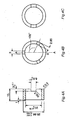
- Figure 3 shows the shape of a disc used in the examples; and
- Figure 4 shows the shape of the ring used in the examples.
- The inventors studied coats for covering the sliding parts of sliding members with the aim of further reducing the friction coefficient and wear quantity of the sliding part of a sliding member which is operated in a water-based environment while improving resistance to seizure under high surface pressure. As a result, they reached the present invention upon discovering that it was sufficient to form a 0.1 to 5 µm amorphous carbon (diamond-like carbon, sometimes abbreviated hereunder as "DLC") film with a hardness of 7 to 25 GPa on at least one sliding surface of the aforementioned sliding part.
- The aforementioned DLC is a carbon which has a structure in which diamond and graphite structures are mixed, and in addition to being called amorphous carbon as mentioned above it is sometimes called non-crystalline carbon, i-carbon, diamond-like carbon or the like. As described below, films comprising hydrogen and having C-H hydrocarbon bonds are also included in DLC films as long as these are specified as "hydrogenated amorphous carbon film".
- The reason that the present invention is limited to coatings for covering sliding parts of sliding members is described below.
- First, in the present invention, a DLC film is formed as described above on the surface of a sliding member to be operated in a water-based environment. This is because the DLC film can more efficiently enhance wear resistance in a water-based environment than another metal film, metal compound film or inorganic compound film. The mechanism by which friction and wear are reduced in this way by the formation of the DLC film is thought to be as follows. The surface of the DLC film is altered by surface pressure and heat generated during sliding, forming a soft transfer layer on the counterpart, so that even when this counterpart undergoes friction it has a low friction coefficient because of the shear generated in the transfer layer and also because the transfer layer acts as a protective film for the counterpart. It is also thought that friction is low because the DLC is carbonized (graphitized) during sliding in a water-based environment and water in the environment is adsorbed by the graphite.
- After grasping these advantages of DLC film, the inventors discovered as the result of further research that wear resistance in water-based environments could be further improved and that specifically reductions in the friction coefficient and wear quantity could be reliably achieved even in water-based environments if the DLC film were formed with a hardness in a specific range. That is, a DLC film with a hardness of 7 GPa or more is formed in the present invention. If hardness is too low, the DLC film rapidly wears without achieving the sufficient wear resistance of the DLC film itself, which allows the base materials to contact with one another, causing seizure. Preferably the GPa of the DLC film is 10 or more.
- However, if the DLC film is too hard, although the DLC film itself will be less liable to wear, the sliding surface of the other sliding member which is its counterpart will be more liable to wear (this property is sometimes referred to hereunder as "counterpart attack"). In the past DLC films have been used as coating films in many cases, but these films have been very hard with hardness values of HV 3000 to 4000 (or 30 to 40 GPa given HV 1000 = 10 GPa). Since significant wear of the sliding counterpart occurs when such a hard coat is formed only on one surface of a sliding member, the sliding member cannot be operated satisfactorily for a long time. In the present invention, the hardness of the coated DLC film is 25 GPa or less, or preferably 20 GPa or less.
- The aforementioned hardness of the DLC film was measured with a nanoindenter. Specifically, the loading-unloading curve was measured at each of five points under maximum loads of 2, 5, 7, 10 and 20 mN using a Berkovich pyramidal indenter, and hardness was calculated. In calculating hardness, indenter shape was corrected for using the methods described in Phil. Mag. 74 (1996), 1097, A. Shimamoto et al.
- One method of controlling the hardness of the DLC film within the specified range as described above is to adjust the bias voltage when depositing a film with a UBMS (unbalanced magnetron sputtering) device or the like. In the method, high bias voltage causes the hardness to increase. Hardness can also be controlled by adjusting the hydrogen content of the DLC film. High hydrogen content causes the hardness to reduce.
- The thickness of the aforementioned DLC film must be controlled in the present invention. If the film is too thin, the DLC film will be lost through initial wear in the breaking-in process during initial use, exposing the base material and making it liable to seizure. Therefore, the thickness of the aforementioned DLC film is 0.1 µm or more, or preferably 0.5 µm or more. A thicker DLC film is better from the standpoint of reducing the friction coefficient and wear quantity and increasing surface pressure at seizure, but if the film is too thick, the coat will be liable to peeling on the edge in particular due to the internal stress of the DLC film. Therefore, the film thickness is specified as 5 µm or less in the present invention, or preferably 3 µm or less.
- If a hydrogenated amorphous carbon film containing a fixed amount of hydrogen is formed as the aforementioned DLC film, the wear quantity and friction coefficient can be more reduced than a DLC film containing no hydrogen. The reasons for this are not necessarily clear in detail, but it is thought that when C-H bonds are present on the outermost surface of a DLC coat, the surface energy is different than it is when the outermost coat consists solely of carbon, with the result that water is adsorbed more easily.
- The amount of hydrogen in the DLC film overall is preferably 5 at% or more in order to achieve these effects. Since the sliding properties of a DLC film differ depending on the sliding environment, it is important to select the optimal amount of hydrogen according to the sliding environment. The wear quantity and friction coefficient can be sufficiently reduced with a hydrogenated amorphous carbon film in which hydrogen constitutes 25 at% or more of the DLC film. However, wear resistance is actually reduced if the hydrogenated amorphous carbon film is formed with too much hydrogen, so the amount of hydrogen in the DLC film overall is 40 at% or less.
- In addition to consisting of carbon alone or of carbon and hydrogen as described above, the DLC film of the present invention may also comprise 10 at% or less of a total of Si, Cr and other added elements as third elements.
- In the present invention, it is desirable that the aforementioned DLC film be formed on both sliding surfaces of the sliding part because the wear quantity and friction coefficient of the sliding member are dramatically reduced and resistance to high surface pressure is greatly improved thereby. It is thought that the wear quantity and friction coefficient of the sliding member can be greatly reduced by forming DLC films on both sliding surfaces of the sliding part because the aforementioned transfer layer is much more easily formed and more strongly bound to the DLC film surface of the counterpart.
- The sliding member of the present invention has the aforementioned DLC film formed on at least one sliding surface of the sliding part, and in a preferred mode has the DLC film formed on both sliding surfaces of the sliding part, but is not otherwise limited. Consequently, in addition to the aforementioned mode in which the DLC film is formed only on the sliding part it may have a mode in which the DLC film is also formed at sites other than the sliding part.
- When the DLC film is formed at multiple locations (for example, when the DLC film is formed on both sliding surfaces of the sliding part or when the DLC film is formed on multiple sliding parts), the films do not necessarily have to be of the same type as long as they fulfill the respective conditions specified in the present invention, and they may differ from one other in hardness, thickness and hydrogen content within the aforementioned specified ranges.
- The method of forming the aforementioned DLC film (deposition method) is not particularly specified, but because the amount of hydrogen in the coat is difficult to control in the case of the CVD method of deposition using a hydrocarbon gas as the raw material, the arc method or sputtering method using a solid carbon source is recommended. Film deposition by sputtering is particularly recommended. In the arc method, arc discharge of the carbon evaporation source is accompanied by a scattering of numerous particles which may detract from the wear resistance properties if they adhere to the coat; while in the sputtering method, almost no particles are generated, and the amount of hydrogen in the coat can be controlled at will by including a hydrocarbon gas such as methane or ethylene in the process.
- The amount of hydrogen in the DLC film is largely determined by the amount of hydrocarbon gas, but even given the same total amount of hydrogen in the hydrocarbon gas it is easier to increase the hydrogen content of the DLC film using a gas (such as methane gas or ethylene gas) which contains many hydrogen atoms per molecule. The amount of hydrogen in the DLC film is also dependent on the bias voltage during film deposition, and as a general rule raising the bias voltage will tend to decrease the hydrogen content of the DLC film given the same amount of methane. The hydrogen content of the DLC film can be kept within the aforementioned range if these conditions are controlled during film deposition. Bias voltage can be controlled in either the sputtering method or arc method for purposes of controlling the hardness of the DLC film.
- A metal coat or inorganic metal compound coat can be formed as an intermediate layer between the DLC film and base material of the present invention to the extent that the wear resistance and the like of the sliding member are not adversely affected. For example a coat consisting of Si, Ti, Zr, Cr, W or Mo alone or of an oxide, nitride, carbide or the like of these can be formed to a thickness of about 0.1 to 1 µm. The method of forming this intermediate layer is not restricted and a sputtering or arc method similar to that used for the aforementioned DLC layer is recommended.
- There are no particular limits on the base material of the sliding member of the present invention, and for example a cemented carbide, stainless steel, alloy tool steel, high speed steel or other iron alloy, titanium alloy, aluminum alloy or copper alloy, glass, alumina or other ceramic or resin or other base material can be used. Moreover, the sliding member of the present invention is a combination of sliding members to be operated in water-based environments, and specific examples include hydraulic pistons, hydraulic cylinders, valve plates and others which undergo relative movement.
- The present invention is explained in more detail below using examples. However, the present invention is not limited by the following examples, but can be accomplished with the addition of suitable changes, which are all included within the technical scope of the present invention to the extent that they conform to what is stated above and below.
- A DLC film was formed using the unbalanced magnetron sputtering device 1 having multiple evaporation sources shown in Figure 1. This sputtering device 1 was equipped with 4
evaporation sources 4 through 6, andCr evaporation source 4,W evaporation source 5 and twoC evaporation sources 6 were used in forming the intermediate layer described below and the DLC film. - As the base material, a (mirror polished) cemented carbide plate was used for purposes of measuring hardness and hydrogen content, while the test piece described below was used for the ball-on-disc sliding test and the ring-on-disc seizure load evaluation test. For purposes of film deposition, the aforementioned base material was first ultrasound washed in ethanol, then set on a
base material stage 2 inside the sputtering device 1, which was exhausted to a vacuum of 1 x 10⁻³ Pa or less, after whichbase material 3 was heated to about 300°C todegas base material 3. Next, the base material was maintained at a temperature of about 200°C while being cleaned with Ar ions. - The intermediate layer was then formed, followed by the DLC layer. In this test, as shown in Tables 1 and 2, either
Cr/Cr-C/DLC film layered coat
(a layered coat consisting of a Cr film, Cr carbide film and DLC film formed in that order to a base material) or
Cr/W/W-C/DLC film layered coat
(a layered coat consisting of a Cr film, W film, W carbide film and DLC film formed in that order on a base material) was formed. - The Cr layer or W layer which was the aforementioned intermediate layer was formed by sputtering using a Cr target or W target in a pure Ar atmosphere. The Cr carbide layer or W carbide layer was formed by gradually decreasing the power input to the Cr target or W target while increasing the power input to the carbon target in an Ar-CH4 atmosphere (5%). The intermediate layer was 0.5 to 1 µm thick in all cases.
- The aforementioned DLC film was formed with an input power to the target of 2.5 kW using an Ar or Ar+CH4 mixed gas under a total pressure of 0.6 Pa. The substrate bias was applied in a range of 0 to 150 V so that the substrate (object to be treated) would have minus potential relative to the earth potential. The thickness of the DLC film was 1 to 2 µm except as specified in Tables 1 and 2. An untreated test piece having no intermediate layer or DLC film was also prepared as a comparative sample.
- The test pieces with formed intermediate layers and DLC films and the untreated test piece were evaluated as follows.
- The coat hardness was measured with a nanoindenter. The hardness of the DLC film alone was measured here. The hydrogen content of the DLC film was measured by ERDA (Elastic Recoil Detection Analysis), and the amount of hydrogen as a percentage of the carbon and hydrogen constituting the DLC film (at%) was calculated.
- To evaluate wear resistance, a ball-on-disc sliding test was performed under the following conditions, and the friction coefficient, relative ball wear quantity and relative disc wear quantity were measured. The results are shown in Table 1. As indicated in Table 1, the relative ball wear quantity and relative disc wear quantity values show the measured values multiplied by 109.
- Discs; SUS630 (heat treatment H900, hardness HV400) coated with various DLC films or not coated.
Size; φ55 mm x 5 mm thick, mirror polished on one side
Balls; 3/8 inch uncoated SUS630 (heat treatment H900, hardness HV400)
Sliding speed; 0.5 m/s
Vertical load; 2N
Lubrication; Distilled water (with disc immersed as shown in Figure 2)
Sliding distance; 5000 m[Table 1] Test No. Disc side Ring side Friction Relative disc wear Relative ball wear amount (mm3/N-mH(×109) Coat Methane (vol%) Bias voltage (V) Hardness (GPa) Hydrogen (at%) Coat coefficient amount (mm3/N·m)(×109) 1 None - - - - None 0.5 8.99x10⁴ 5.68x10³ 2 Cr/Cr-C/DLC 10 0 0 5 30 None 0.08 610.2 8.918 3 Cr/CrC/DLC 10 0 50 7 29 None 0.1 82.47 2.641 4 Cr/CrC/DLC 10 75 11 29 None 0.11 53.5 25.3 5 Cr/Cr-C/DLC 10 100 15 27 None 0.12 32.99 64.44 6 Cr/W/W-C/DLC 10 150 21 25 None 0.15 35.73 75.4 7 Cr/W/W-C/DLC 10 250 30 23 None 0.17 32.7 157 8 Cr/W/W-C/DLC 0 100 12 2.5 None 0.16 29.7 74.6 9 Cr/W/W-C/DLC 10 100 15 27 None 0.12 32.99 64.44 10 Cr/W/W-C/DLC 20 100 13.5 35 None 0.13 35.7 73.5 11 Cr/W/W-C/DLC 30 100 6 43 None 0.14 857 8.78 12 DLC 10 100 15 27 None Could not evaluate due to peeling 13 Cr/Cr-C/DLC* 10 150 15.0 30.0 None 0.1-0.5 Substrate exposed immediately after start of test 14 Cr/Cr-C/DLC* 10 150 15.0 30.0 None 0.13 34.54 65.2 15 Cr/Cr-C/DLC* 10 150 15.0 30.0 None 0.13 37.56 63.2 *No. 13: DLC thickness 0.05 µm. No. 14: DLC thickness 02 µm, No. 15: DLC thickness 4.5 µm - The following can be deduced from Table 1. Because coats according to the present invention were formed in Nos. 3 to 6, 9, 10, 14 and 15, the friction coefficients are low and wear quantity of both the disc and ball is controlled. By contrast, because the conditions of the present invention are not met in Nos. 1, 2, 7 and 13, the friction coefficients are higher and wear quantities of the disc and ball are remarkable. That is, because in No. 1 no DLC film is formed while in No. 2 the DLC film is not hard enough, there is considerable wear quantity especially of the disc in the wear test. Because the DLC film is too hard in No. 7, the DLC film exhibited counterpart attack, and there is considerable wear quantity especially of the ball in the wear test. In No. 13, the base material was exposed immediately after the start of the test because the DLC film was too thin.
- In Nos. 8 and 11, the amount of hydrogen in the DLC coat was outside the recommended range, and these examples show that increases in friction coefficient and wear quantity can be reliably controlled if the hydrogen content of the DLC film is also controlled.
- In No. 12 the DLC film was coated directly on the base material without the aforementioned intermediate layer, and in this case the friction coefficient and wear quantity could not be measured due to peeling in the wear test.
- Next, to evaluate resistance to high surface pressure (resistance to seizure under high surface pressure conditions), a ring-on-disc seizure load evaluation test was performed under the following conditions using samples in which either the ring or the disc or both had been coated with a DLC film as shown in Table 2, and the friction coefficients, seizure loads and disc wear quantities were measured. The results are shown together in Table 2.
- Discs; SUS630 coated with various DLC films or uncoated (heat treatment H900, hardness HV400).
- Size; φ34 mm x 5 mm thick, mirror polished on one side (side view shown in Figure 3).
- Rings; SUS630 coated with various DLC films or uncoated (heat treatment H900, hardness HV400). Size: inner diameter 20 m, outer diameter 25 mm, contact area 25.65 mm3 (side view and cross-section shown in Figure 4).
Contact area; 25.65 mm
Sliding speed; 1.0 m/s
Vertical load; 50 to 900 N, increased in steps (surface pressure conversion 1.95 to 35 MPa)
Lubrication; Distilled water (disc immersed as in Figure 2 above)
Sliding distance; 500 m for each load
- The following can be deduced from Table 2. Because Nos. 5, 6, 8, 9, 14, 16, 19 and 20 have a DLC film stipulated by the present invention coated on at least one of the ring and disc, resistance to surface pressure is high, with high surface pressures at seizure, and the friction coefficients are also low. Because a DLC film stipulated the present invention is coated on both the ring and disc in Nos. 7, 10 and 15, the surface pressures at seizure at high, the friction coefficients are very low and wear quantity of the disc is controlled.
- In contrast, when neither the ring nor the disc was coated with a DLC film stipulated by the present invention, either the surface pressure at seizure was much lower so that the disc wear area could not be measured due to seizure, or the disc wear area was extremely large. The friction coefficient values were also high. That is, these problems occurred in No. 1 because there was no DLC film and in Nos. 2 through 4 because both the rings and discs were coated with DLC films of very low hardness. The same problems occurred in Nos. 11 and 12 because either the ring or disc was coated with a DLC film of very low hardness while the other was coated with a very hard DLC film, and in No. 13 because both the ring and disc were coated with very hard DLC films.
- In No. 17 the DLC film was coated directly on the base material without the aforementioned intermediate layer, and in this case the surface pressure at seizure, friction coefficient and disc wear area could not be measured due to peeling during the wear test.
- In No. 18 the surface pressure at seizure was very low because the DLC film was so thin, and the disc wear area could not be measured due to seizure.
Claims (3)
- A sliding member with excellent wear resistance in water-based environments, which is a combination of sliding members to be operated in water-based environments, wherein an amorphous carbon film is formed with a thickness of 0.1 to 5 µm and a hardness of 7 to 25 GPa on at least one of the sliding surfaces of the sliding part of the sliding member.
- The sliding member according to Claim 1, wherein said amorphous carbon film is a hydrogenated amorphous carbon film comprising 5 to 40 at% hydrogen.
- The sliding member according to Claim 1 or 2, wherein said amorphous carbon film is formed on both sliding surfaces of said sliding part.
Applications Claiming Priority (1)
| Application Number | Priority Date | Filing Date | Title |
|---|---|---|---|
| JP2004328961A JP2006138404A (en) | 2004-11-12 | 2004-11-12 | Sliding member with excellent abrasion resistance in wet environment |
Publications (2)
| Publication Number | Publication Date |
|---|---|
| EP1657323A1 true EP1657323A1 (en) | 2006-05-17 |
| EP1657323B1 EP1657323B1 (en) | 2007-12-12 |
Family
ID=35457059
Family Applications (1)
| Application Number | Title | Priority Date | Filing Date |
|---|---|---|---|
| EP20050023195 Revoked EP1657323B1 (en) | 2004-11-12 | 2005-10-24 | Sliding member with excellent wear resistance in water-based environments |
Country Status (6)
| Country | Link |
|---|---|
| US (1) | US7498083B2 (en) |
| EP (1) | EP1657323B1 (en) |
| JP (1) | JP2006138404A (en) |
| AT (1) | ATE380889T1 (en) |
| DE (1) | DE602005003762T2 (en) |
| DK (1) | DK1657323T3 (en) |
Cited By (8)
| Publication number | Priority date | Publication date | Assignee | Title |
|---|---|---|---|---|
| EP1767662B1 (en) * | 2005-09-10 | 2009-12-16 | Schaeffler KG | Wear resistant coating and process of its manufacture |
| WO2010004396A3 (en) * | 2008-06-30 | 2010-02-25 | Eaton Corporation | Friction- and wear-reducing coating |
| EP2233602A3 (en) * | 2009-03-24 | 2010-10-20 | Kabushiki Kaisha Kobe Seiko Sho | DLC film and coated member |
| EP2103711A4 (en) * | 2006-12-28 | 2011-07-20 | Jtekt Corp | Highly corrosion-resistant members and processes for production thereof |
| WO2013129939A1 (en) * | 2012-02-28 | 2013-09-06 | Aker Subsea As | Dlc-coated gate valve in petroleum production or water injection |
| US8550792B2 (en) | 2008-06-30 | 2013-10-08 | Eaton Corporation | Energy conversion device and method of reducing friction therein |
| US8728621B2 (en) | 2008-10-29 | 2014-05-20 | Ntn Corporation | Hard multilayer film formed body and method for manufacturing same |
| EP2092157B2 (en) † | 2006-12-15 | 2022-02-09 | Vetco Gray Inc. | Low friction coatings for dynamically engaging load bearing surfaces |
Families Citing this family (16)
| Publication number | Priority date | Publication date | Assignee | Title |
|---|---|---|---|---|
| US7866342B2 (en) | 2002-12-18 | 2011-01-11 | Vapor Technologies, Inc. | Valve component for faucet |
| US7866343B2 (en) | 2002-12-18 | 2011-01-11 | Masco Corporation Of Indiana | Faucet |
| US8220489B2 (en) | 2002-12-18 | 2012-07-17 | Vapor Technologies Inc. | Faucet with wear-resistant valve component |
| US8555921B2 (en) | 2002-12-18 | 2013-10-15 | Vapor Technologies Inc. | Faucet component with coating |
| JP4400603B2 (en) * | 2006-09-12 | 2010-01-20 | 株式会社日立製作所 | Member with hard carbon coating |
| JP4503097B2 (en) * | 2008-02-06 | 2010-07-14 | 神奈川県 | DLC-coated sliding member and manufacturing method thereof |
| DE102008016864B3 (en) * | 2008-04-02 | 2009-10-22 | Federal-Mogul Burscheid Gmbh | piston ring |
| JP5393108B2 (en) * | 2008-10-29 | 2014-01-22 | Ntn株式会社 | Manufacturing method of hard multilayer film molded body |
| CN102002684B (en) * | 2009-08-31 | 2014-07-30 | 日立金属株式会社 | Slide part |
| US9528180B2 (en) * | 2011-03-02 | 2016-12-27 | Oerlikon Surface Solutions Ag, Pfaffikon | Sliding component coated with metal-comprising carbon layer for improving wear and friction behavior by tribological applications under lubricated conditions |
| DE102011076410A1 (en) * | 2011-05-24 | 2012-11-29 | Schaeffler Technologies AG & Co. KG | machine element |
| US9347491B2 (en) * | 2011-09-22 | 2016-05-24 | Ntn Corporation | Hard film, hard film formed body, and rolling bearing |
| JP5938321B2 (en) * | 2011-09-22 | 2016-06-22 | Ntn株式会社 | Hard film and film forming method thereof, hard film forming body and manufacturing method thereof |
| AT511605B1 (en) * | 2011-12-12 | 2013-01-15 | High Tech Coatings Gmbh | CARBON COATING COATING |
| US9657384B2 (en) | 2013-03-22 | 2017-05-23 | Nittan Valve Co., Ltd. | DLC film coating and coated valve lifter |
| US9926622B2 (en) * | 2015-11-12 | 2018-03-27 | Uchicago Argonne, Llc | Methods for forming pitting resistant carbon coating |
Citations (6)
| Publication number | Priority date | Publication date | Assignee | Title |
|---|---|---|---|---|
| WO1995023878A1 (en) * | 1994-03-03 | 1995-09-08 | Diamonex, A Unit Of Monsanto Company | Diamond-like carbon coated transducers for magnetic recording media |
| JPH10184692A (en) | 1996-02-20 | 1998-07-14 | Ebara Corp | Water-lubricated bearing or water-lubricated seal |
| JP2000128516A (en) | 1998-10-30 | 2000-05-09 | Riken Corp | Composite diamond-like carbon film with low abrasion and excellent adhesion |
| EP1067211A1 (en) * | 1999-07-08 | 2001-01-10 | Sumitomo Electric Industries, Ltd. | Hard coating and coated member |
| JP2003026414A (en) | 2001-07-17 | 2003-01-29 | Sumitomo Electric Ind Ltd | Amorphous carbon coating, method for producing amorphous carbon coating, and member coated with amorphous carbon coating |
| EP1411145A1 (en) * | 2002-10-16 | 2004-04-21 | Nissan Motor Company, Limited | Sliding structure for automotive engine |
Family Cites Families (22)
| Publication number | Priority date | Publication date | Assignee | Title |
|---|---|---|---|---|
| SU1593353A1 (en) * | 1987-11-09 | 1997-03-10 | Е.К. Волювач | Sliding friction pair |
| JPH08233121A (en) | 1995-02-28 | 1996-09-10 | Kyocera Corp | Faucet valve |
| JPH0996367A (en) * | 1995-09-29 | 1997-04-08 | Kyocera Corp | Disc valve |
| EP0896640B1 (en) * | 1996-04-22 | 2002-02-06 | N.V. Bekaert S.A. | Diamond-like nanocomposite compositions |
| EP0821077A3 (en) | 1996-06-27 | 2000-09-06 | Nissin Electric Co., Ltd. | Object coated with carbon film and method of manufacturing the same |
| JPH10101461A (en) * | 1996-09-30 | 1998-04-21 | Ntn Corp | Ceramic sliding part |
| US6726993B2 (en) | 1997-12-02 | 2004-04-27 | Teer Coatings Limited | Carbon coatings, method and apparatus for applying them, and articles bearing such coatings |
| GB2348158A (en) | 1999-03-16 | 2000-09-27 | Teer Coatings Ltd | Lubricated cutting |
| JP2001124220A (en) | 1999-10-27 | 2001-05-11 | Ngk Spark Plug Co Ltd | Ceramic valve and valve unit using the same |
| JP4560964B2 (en) * | 2000-02-25 | 2010-10-13 | 住友電気工業株式会社 | Amorphous carbon coated member |
| DE10018143C5 (en) * | 2000-04-12 | 2012-09-06 | Oerlikon Trading Ag, Trübbach | DLC layer system and method and apparatus for producing such a layer system |
| US6994474B2 (en) * | 2001-05-29 | 2006-02-07 | Nsk Ltd. | Rolling sliding member and rolling apparatus |
| EP1486695B1 (en) * | 2001-09-27 | 2011-04-06 | Kabushiki Kaisha Toyota Chuo Kenkyusho | High friction sliding member |
| JP4360082B2 (en) * | 2001-12-17 | 2009-11-11 | 住友電気工業株式会社 | Method for producing amorphous carbon coating and sliding part with amorphous carbon coating |
| JP2003314712A (en) * | 2002-04-25 | 2003-11-06 | Sumitomo Electric Ind Ltd | Hot water valve |
| JP2006509967A (en) * | 2002-04-25 | 2006-03-23 | ユナキス・バルツェルス・アクチェンゲゼルシャフト | Structured layer system |
| DE10223844B4 (en) * | 2002-05-28 | 2013-04-04 | Danfoss A/S | Water hydraulic machine |
| JP4085699B2 (en) * | 2002-06-04 | 2008-05-14 | トヨタ自動車株式会社 | Sliding member and manufacturing method thereof |
| JP4300762B2 (en) * | 2002-07-10 | 2009-07-22 | 日新電機株式会社 | Carbon film-coated article and method for producing the same |
| US6904935B2 (en) * | 2002-12-18 | 2005-06-14 | Masco Corporation Of Indiana | Valve component with multiple surface layers |
| JP4229313B2 (en) | 2003-01-21 | 2009-02-25 | 株式会社豊田中央研究所 | Sliding member for wet clutch and wet clutch device |
| JP3876848B2 (en) * | 2003-03-27 | 2007-02-07 | 日新電機株式会社 | Sliding mechanism and power switchgear using the same |
-
2004
- 2004-11-12 JP JP2004328961A patent/JP2006138404A/en active Pending
-
2005
- 2005-10-14 US US11/249,266 patent/US7498083B2/en not_active Expired - Lifetime
- 2005-10-24 DK DK05023195T patent/DK1657323T3/en active
- 2005-10-24 EP EP20050023195 patent/EP1657323B1/en not_active Revoked
- 2005-10-24 AT AT05023195T patent/ATE380889T1/en not_active IP Right Cessation
- 2005-10-24 DE DE200560003762 patent/DE602005003762T2/en not_active Expired - Lifetime
Patent Citations (6)
| Publication number | Priority date | Publication date | Assignee | Title |
|---|---|---|---|---|
| WO1995023878A1 (en) * | 1994-03-03 | 1995-09-08 | Diamonex, A Unit Of Monsanto Company | Diamond-like carbon coated transducers for magnetic recording media |
| JPH10184692A (en) | 1996-02-20 | 1998-07-14 | Ebara Corp | Water-lubricated bearing or water-lubricated seal |
| JP2000128516A (en) | 1998-10-30 | 2000-05-09 | Riken Corp | Composite diamond-like carbon film with low abrasion and excellent adhesion |
| EP1067211A1 (en) * | 1999-07-08 | 2001-01-10 | Sumitomo Electric Industries, Ltd. | Hard coating and coated member |
| JP2003026414A (en) | 2001-07-17 | 2003-01-29 | Sumitomo Electric Ind Ltd | Amorphous carbon coating, method for producing amorphous carbon coating, and member coated with amorphous carbon coating |
| EP1411145A1 (en) * | 2002-10-16 | 2004-04-21 | Nissan Motor Company, Limited | Sliding structure for automotive engine |
Non-Patent Citations (1)
| Title |
|---|
| A. SHIMAMOTO, PHIL. MAG., vol. 74, 1996, pages 1097 |
Cited By (15)
| Publication number | Priority date | Publication date | Assignee | Title |
|---|---|---|---|---|
| EP1767662B1 (en) * | 2005-09-10 | 2009-12-16 | Schaeffler KG | Wear resistant coating and process of its manufacture |
| EP2092157B2 (en) † | 2006-12-15 | 2022-02-09 | Vetco Gray Inc. | Low friction coatings for dynamically engaging load bearing surfaces |
| EP2103711A4 (en) * | 2006-12-28 | 2011-07-20 | Jtekt Corp | Highly corrosion-resistant members and processes for production thereof |
| US8550792B2 (en) | 2008-06-30 | 2013-10-08 | Eaton Corporation | Energy conversion device and method of reducing friction therein |
| US8039096B2 (en) * | 2008-06-30 | 2011-10-18 | Eaton Corporation | Friction- and wear-reducing coating |
| WO2010004396A3 (en) * | 2008-06-30 | 2010-02-25 | Eaton Corporation | Friction- and wear-reducing coating |
| US8728621B2 (en) | 2008-10-29 | 2014-05-20 | Ntn Corporation | Hard multilayer film formed body and method for manufacturing same |
| EP2233602A3 (en) * | 2009-03-24 | 2010-10-20 | Kabushiki Kaisha Kobe Seiko Sho | DLC film and coated member |
| US8574715B2 (en) | 2009-03-24 | 2013-11-05 | Kobe Steel, Ltd. | Laminated film and laminated film-coated member |
| WO2013129939A1 (en) * | 2012-02-28 | 2013-09-06 | Aker Subsea As | Dlc-coated gate valve in petroleum production or water injection |
| GB2514305A (en) * | 2012-02-28 | 2014-11-19 | Aker Subsea As | DLC-coated gate valve in petroleum production or water injection |
| CN104254637A (en) * | 2012-02-28 | 2014-12-31 | 阿克海底公司 | Dlc-coated gate valve in petroleum production or water injection |
| GB2514305B (en) * | 2012-02-28 | 2017-10-11 | Aker Solutions As | DLC-coated gate valve in petroleum production or water injection |
| US9791051B2 (en) | 2012-02-28 | 2017-10-17 | Aker Subsea As | DLC-coated gate valve in petroleum production or water injection |
| EP2820167B1 (en) | 2012-02-28 | 2017-12-27 | Aker Subsea AS | Dlc-coated gate valve in petroleum production or water injection |
Also Published As
| Publication number | Publication date |
|---|---|
| HK1089214A1 (en) | 2006-11-24 |
| US7498083B2 (en) | 2009-03-03 |
| ATE380889T1 (en) | 2007-12-15 |
| DK1657323T3 (en) | 2008-01-07 |
| DE602005003762T2 (en) | 2008-12-04 |
| JP2006138404A (en) | 2006-06-01 |
| EP1657323B1 (en) | 2007-12-12 |
| DE602005003762D1 (en) | 2008-01-24 |
| US20060105172A1 (en) | 2006-05-18 |
Similar Documents
| Publication | Publication Date | Title |
|---|---|---|
| EP1657323B1 (en) | Sliding member with excellent wear resistance in water-based environments | |
| Chang et al. | Microstructure and adhesion characteristics of diamond-like carbon films deposited on steel substrates | |
| EP0884509B1 (en) | Disc valve | |
| US8039096B2 (en) | Friction- and wear-reducing coating | |
| EP2316983B1 (en) | Nitrogen-containing amorphous carbon and amorphous carbon layered film, and sliding member | |
| CN1103878C (en) | Coated rolling element bearing | |
| EP2233602B1 (en) | DLC film and coated member | |
| EP1154035B1 (en) | Amorphous carbon film containing oxide | |
| EP1905863A2 (en) | Slide member | |
| US20240093344A1 (en) | Hard carbon coatings with improved adhesion strength by means of hipims and method thereof | |
| EP3877569B1 (en) | Ta-c based coatings with improved hardness | |
| EP2206920B1 (en) | Sliding member for compressor | |
| CN1729368A (en) | Valve components with multiple surface layers | |
| CN1853832A (en) | Cutting tool coated with hard alloy | |
| JP6756641B2 (en) | piston ring | |
| EP3318656A1 (en) | Sliding member and piston ring | |
| Yao et al. | Evaluation on wear behavior of Cr–Ag–N and Cr–W–N PVD nanocomposite coatings using two different types of tribometer | |
| JP2004169137A (en) | Sliding member | |
| Zhang et al. | The effect of deep-case oxygen hardening on the tribological behaviour of aC: H DLC coatings on Ti6Al4V alloy | |
| Podgornik et al. | Improvement in galling performance through surface engineering | |
| Kao et al. | Optimum MoS2–Cr coating for sliding against copper, steel and ceramic balls | |
| Ramalingam et al. | Reactively sputtered TiN coatings for tribological applications | |
| CN105648410A (en) | Titanium nitride/titanium carbide coating, preparation method thereof and coated part with titanium nitride/titanium carbide coating | |
| HK1089214B (en) | Sliding member with excellent wear resistance in water-based environments | |
| Batista et al. | Process developments towards producing well adherent duplex PAPVD coatings |
Legal Events
| Date | Code | Title | Description |
|---|---|---|---|
| PUAI | Public reference made under article 153(3) epc to a published international application that has entered the european phase |
Free format text: ORIGINAL CODE: 0009012 |
|
| 17P | Request for examination filed |
Effective date: 20051103 |
|
| AK | Designated contracting states |
Kind code of ref document: A1 Designated state(s): AT BE BG CH CY CZ DE DK EE ES FI FR GB GR HU IE IS IT LI LT LU LV MC NL PL PT RO SE SI SK TR |
|
| AX | Request for extension of the european patent |
Extension state: AL BA HR MK YU |
|
| 17Q | First examination report despatched |
Effective date: 20060714 |
|
| REG | Reference to a national code |
Ref country code: HK Ref legal event code: DE Ref document number: 1089214 Country of ref document: HK |
|
| AKX | Designation fees paid |
Designated state(s): AT BE BG CH CY CZ DE DK EE ES FI FR GB GR HU IE IS IT LI LT LU LV MC NL PL PT RO SE SI SK TR |
|
| 17Q | First examination report despatched |
Effective date: 20060714 |
|
| GRAP | Despatch of communication of intention to grant a patent |
Free format text: ORIGINAL CODE: EPIDOSNIGR1 |
|
| GRAS | Grant fee paid |
Free format text: ORIGINAL CODE: EPIDOSNIGR3 |
|
| GRAA | (expected) grant |
Free format text: ORIGINAL CODE: 0009210 |
|
| AK | Designated contracting states |
Kind code of ref document: B1 Designated state(s): AT BE BG CH CY CZ DE DK EE ES FI FR GB GR HU IE IS IT LI LT LU LV MC NL PL PT RO SE SI SK TR |
|
| REG | Reference to a national code |
Ref country code: GB Ref legal event code: FG4D |
|
| REG | Reference to a national code |
Ref country code: CH Ref legal event code: EP |
|
| REG | Reference to a national code |
Ref country code: DK Ref legal event code: T3 |
|
| REG | Reference to a national code |
Ref country code: IE Ref legal event code: FG4D |
|
| REF | Corresponds to: |
Ref document number: 602005003762 Country of ref document: DE Date of ref document: 20080124 Kind code of ref document: P |
|
| PG25 | Lapsed in a contracting state [announced via postgrant information from national office to epo] |
Ref country code: SE Free format text: LAPSE BECAUSE OF FAILURE TO SUBMIT A TRANSLATION OF THE DESCRIPTION OR TO PAY THE FEE WITHIN THE PRESCRIBED TIME-LIMIT Effective date: 20080312 Ref country code: CH Free format text: LAPSE BECAUSE OF FAILURE TO SUBMIT A TRANSLATION OF THE DESCRIPTION OR TO PAY THE FEE WITHIN THE PRESCRIBED TIME-LIMIT Effective date: 20071212 Ref country code: LI Free format text: LAPSE BECAUSE OF FAILURE TO SUBMIT A TRANSLATION OF THE DESCRIPTION OR TO PAY THE FEE WITHIN THE PRESCRIBED TIME-LIMIT Effective date: 20071212 |
|
| PG25 | Lapsed in a contracting state [announced via postgrant information from national office to epo] |
Ref country code: PL Free format text: LAPSE BECAUSE OF FAILURE TO SUBMIT A TRANSLATION OF THE DESCRIPTION OR TO PAY THE FEE WITHIN THE PRESCRIBED TIME-LIMIT Effective date: 20071212 Ref country code: SI Free format text: LAPSE BECAUSE OF FAILURE TO SUBMIT A TRANSLATION OF THE DESCRIPTION OR TO PAY THE FEE WITHIN THE PRESCRIBED TIME-LIMIT Effective date: 20071212 Ref country code: FI Free format text: LAPSE BECAUSE OF FAILURE TO SUBMIT A TRANSLATION OF THE DESCRIPTION OR TO PAY THE FEE WITHIN THE PRESCRIBED TIME-LIMIT Effective date: 20071212 Ref country code: LT Free format text: LAPSE BECAUSE OF FAILURE TO SUBMIT A TRANSLATION OF THE DESCRIPTION OR TO PAY THE FEE WITHIN THE PRESCRIBED TIME-LIMIT Effective date: 20071212 Ref country code: LV Free format text: LAPSE BECAUSE OF FAILURE TO SUBMIT A TRANSLATION OF THE DESCRIPTION OR TO PAY THE FEE WITHIN THE PRESCRIBED TIME-LIMIT Effective date: 20071212 Ref country code: NL Free format text: LAPSE BECAUSE OF FAILURE TO SUBMIT A TRANSLATION OF THE DESCRIPTION OR TO PAY THE FEE WITHIN THE PRESCRIBED TIME-LIMIT Effective date: 20071212 |
|
| NLV1 | Nl: lapsed or annulled due to failure to fulfill the requirements of art. 29p and 29m of the patents act | ||
| REG | Reference to a national code |
Ref country code: CH Ref legal event code: PL |
|
| PG25 | Lapsed in a contracting state [announced via postgrant information from national office to epo] |
Ref country code: AT Free format text: LAPSE BECAUSE OF FAILURE TO SUBMIT A TRANSLATION OF THE DESCRIPTION OR TO PAY THE FEE WITHIN THE PRESCRIBED TIME-LIMIT Effective date: 20071212 |
|
| ET | Fr: translation filed | ||
| REG | Reference to a national code |
Ref country code: HK Ref legal event code: GR Ref document number: 1089214 Country of ref document: HK |
|
| PG25 | Lapsed in a contracting state [announced via postgrant information from national office to epo] |
Ref country code: IS Free format text: LAPSE BECAUSE OF FAILURE TO SUBMIT A TRANSLATION OF THE DESCRIPTION OR TO PAY THE FEE WITHIN THE PRESCRIBED TIME-LIMIT Effective date: 20080412 Ref country code: CZ Free format text: LAPSE BECAUSE OF FAILURE TO SUBMIT A TRANSLATION OF THE DESCRIPTION OR TO PAY THE FEE WITHIN THE PRESCRIBED TIME-LIMIT Effective date: 20071212 Ref country code: ES Free format text: LAPSE BECAUSE OF FAILURE TO SUBMIT A TRANSLATION OF THE DESCRIPTION OR TO PAY THE FEE WITHIN THE PRESCRIBED TIME-LIMIT Effective date: 20080323 |
|
| PG25 | Lapsed in a contracting state [announced via postgrant information from national office to epo] |
Ref country code: BE Free format text: LAPSE BECAUSE OF FAILURE TO SUBMIT A TRANSLATION OF THE DESCRIPTION OR TO PAY THE FEE WITHIN THE PRESCRIBED TIME-LIMIT Effective date: 20071212 Ref country code: SK Free format text: LAPSE BECAUSE OF FAILURE TO SUBMIT A TRANSLATION OF THE DESCRIPTION OR TO PAY THE FEE WITHIN THE PRESCRIBED TIME-LIMIT Effective date: 20071212 Ref country code: RO Free format text: LAPSE BECAUSE OF FAILURE TO SUBMIT A TRANSLATION OF THE DESCRIPTION OR TO PAY THE FEE WITHIN THE PRESCRIBED TIME-LIMIT Effective date: 20071212 |
|
| PLBI | Opposition filed |
Free format text: ORIGINAL CODE: 0009260 |
|
| PG25 | Lapsed in a contracting state [announced via postgrant information from national office to epo] |
Ref country code: PT Free format text: LAPSE BECAUSE OF FAILURE TO SUBMIT A TRANSLATION OF THE DESCRIPTION OR TO PAY THE FEE WITHIN THE PRESCRIBED TIME-LIMIT Effective date: 20080512 |
|
| PLAX | Notice of opposition and request to file observation + time limit sent |
Free format text: ORIGINAL CODE: EPIDOSNOBS2 |
|
| 26 | Opposition filed |
Opponent name: HAUZER TECHNO COATING BV Effective date: 20080912 |
|
| PG25 | Lapsed in a contracting state [announced via postgrant information from national office to epo] |
Ref country code: GR Free format text: LAPSE BECAUSE OF FAILURE TO SUBMIT A TRANSLATION OF THE DESCRIPTION OR TO PAY THE FEE WITHIN THE PRESCRIBED TIME-LIMIT Effective date: 20080313 |
|
| PGFP | Annual fee paid to national office [announced via postgrant information from national office to epo] |
Ref country code: DK Payment date: 20081022 Year of fee payment: 4 |
|
| PLBB | Reply of patent proprietor to notice(s) of opposition received |
Free format text: ORIGINAL CODE: EPIDOSNOBS3 |
|
| PG25 | Lapsed in a contracting state [announced via postgrant information from national office to epo] |
Ref country code: BG Free format text: LAPSE BECAUSE OF FAILURE TO SUBMIT A TRANSLATION OF THE DESCRIPTION OR TO PAY THE FEE WITHIN THE PRESCRIBED TIME-LIMIT Effective date: 20080312 Ref country code: EE Free format text: LAPSE BECAUSE OF FAILURE TO SUBMIT A TRANSLATION OF THE DESCRIPTION OR TO PAY THE FEE WITHIN THE PRESCRIBED TIME-LIMIT Effective date: 20071212 |
|
| PG25 | Lapsed in a contracting state [announced via postgrant information from national office to epo] |
Ref country code: MC Free format text: LAPSE BECAUSE OF NON-PAYMENT OF DUE FEES Effective date: 20081031 |
|
| PG25 | Lapsed in a contracting state [announced via postgrant information from national office to epo] |
Ref country code: CY Free format text: LAPSE BECAUSE OF FAILURE TO SUBMIT A TRANSLATION OF THE DESCRIPTION OR TO PAY THE FEE WITHIN THE PRESCRIBED TIME-LIMIT Effective date: 20071212 |
|
| PG25 | Lapsed in a contracting state [announced via postgrant information from national office to epo] |
Ref country code: IE Free format text: LAPSE BECAUSE OF NON-PAYMENT OF DUE FEES Effective date: 20081024 |
|
| REG | Reference to a national code |
Ref country code: DK Ref legal event code: EBP |
|
| PG25 | Lapsed in a contracting state [announced via postgrant information from national office to epo] |
Ref country code: LU Free format text: LAPSE BECAUSE OF NON-PAYMENT OF DUE FEES Effective date: 20081024 Ref country code: HU Free format text: LAPSE BECAUSE OF FAILURE TO SUBMIT A TRANSLATION OF THE DESCRIPTION OR TO PAY THE FEE WITHIN THE PRESCRIBED TIME-LIMIT Effective date: 20080613 |
|
| PG25 | Lapsed in a contracting state [announced via postgrant information from national office to epo] |
Ref country code: TR Free format text: LAPSE BECAUSE OF FAILURE TO SUBMIT A TRANSLATION OF THE DESCRIPTION OR TO PAY THE FEE WITHIN THE PRESCRIBED TIME-LIMIT Effective date: 20071212 |
|
| PG25 | Lapsed in a contracting state [announced via postgrant information from national office to epo] |
Ref country code: DK Free format text: LAPSE BECAUSE OF NON-PAYMENT OF DUE FEES Effective date: 20091031 |
|
| PGFP | Annual fee paid to national office [announced via postgrant information from national office to epo] |
Ref country code: FR Payment date: 20101020 Year of fee payment: 6 |
|
| PGFP | Annual fee paid to national office [announced via postgrant information from national office to epo] |
Ref country code: DE Payment date: 20101020 Year of fee payment: 6 |
|
| PGFP | Annual fee paid to national office [announced via postgrant information from national office to epo] |
Ref country code: GB Payment date: 20101020 Year of fee payment: 6 |
|
| RDAF | Communication despatched that patent is revoked |
Free format text: ORIGINAL CODE: EPIDOSNREV1 |
|
| REG | Reference to a national code |
Ref country code: DE Ref legal event code: R064 Ref document number: 602005003762 Country of ref document: DE Ref country code: DE Ref legal event code: R103 Ref document number: 602005003762 Country of ref document: DE |
|
| RDAG | Patent revoked |
Free format text: ORIGINAL CODE: 0009271 |
|
| STAA | Information on the status of an ep patent application or granted ep patent |
Free format text: STATUS: PATENT REVOKED |
|
| 27W | Patent revoked |
Effective date: 20110423 |
|
| GBPR | Gb: patent revoked under art. 102 of the ep convention designating the uk as contracting state |
Effective date: 20110423 |
|
| REG | Reference to a national code |
Ref country code: DE Ref legal event code: R107 Ref document number: 602005003762 Country of ref document: DE Effective date: 20111027 |
|
| PGFP | Annual fee paid to national office [announced via postgrant information from national office to epo] |
Ref country code: IT Payment date: 20081031 Year of fee payment: 4 |