EP1657154A2 - Apparatus for mounting a bicycle electrical component - Google Patents
Apparatus for mounting a bicycle electrical component Download PDFInfo
- Publication number
- EP1657154A2 EP1657154A2 EP05024296A EP05024296A EP1657154A2 EP 1657154 A2 EP1657154 A2 EP 1657154A2 EP 05024296 A EP05024296 A EP 05024296A EP 05024296 A EP05024296 A EP 05024296A EP 1657154 A2 EP1657154 A2 EP 1657154A2
- Authority
- EP
- European Patent Office
- Prior art keywords
- housing
- circuit element
- electronic circuit
- sheet
- bicycle
- Prior art date
- Legal status (The legal status is an assumption and is not a legal conclusion. Google has not performed a legal analysis and makes no representation as to the accuracy of the status listed.)
- Granted
Links
Images



Classifications
-
- B—PERFORMING OPERATIONS; TRANSPORTING
- B62—LAND VEHICLES FOR TRAVELLING OTHERWISE THAN ON RAILS
- B62M—RIDER PROPULSION OF WHEELED VEHICLES OR SLEDGES; POWERED PROPULSION OF SLEDGES OR SINGLE-TRACK CYCLES; TRANSMISSIONS SPECIALLY ADAPTED FOR SUCH VEHICLES
- B62M25/00—Actuators for gearing speed-change mechanisms specially adapted for cycles
- B62M25/08—Actuators for gearing speed-change mechanisms specially adapted for cycles with electrical or fluid transmitting systems
-
- B—PERFORMING OPERATIONS; TRANSPORTING
- B62—LAND VEHICLES FOR TRAVELLING OTHERWISE THAN ON RAILS
- B62M—RIDER PROPULSION OF WHEELED VEHICLES OR SLEDGES; POWERED PROPULSION OF SLEDGES OR SINGLE-TRACK CYCLES; TRANSMISSIONS SPECIALLY ADAPTED FOR SUCH VEHICLES
- B62M9/00—Transmissions characterised by use of an endless chain, belt, or the like
- B62M9/04—Transmissions characterised by use of an endless chain, belt, or the like of changeable ratio
- B62M9/06—Transmissions characterised by use of an endless chain, belt, or the like of changeable ratio using a single chain, belt, or the like
- B62M9/10—Transmissions characterised by use of an endless chain, belt, or the like of changeable ratio using a single chain, belt, or the like involving different-sized wheels, e.g. rear sprocket chain wheels selectively engaged by the chain, belt, or the like
- B62M9/12—Transmissions characterised by use of an endless chain, belt, or the like of changeable ratio using a single chain, belt, or the like involving different-sized wheels, e.g. rear sprocket chain wheels selectively engaged by the chain, belt, or the like the chain, belt, or the like being laterally shiftable, e.g. using a rear derailleur
- B62M9/121—Rear derailleurs
- B62M9/122—Rear derailleurs electrically or fluid actuated; Controls thereof
Definitions
- the present invention is directed to bicycles and, more particularly, to an apparatus for mounting a bicycle electrical component.
- bicycles have been equipped with various electrical components used to facilitate the operation of the bicycle.
- various electrical devices may be used to operate the bicycle transmission or to provide an assisting force to facilitate pedaling the bicycle. See, for example, Japanese Laid-Open Patent Application No. 2004-90915.
- Such transmissions usually include a plurality of front sprockets and a plurality of rear sprockets, wherein the plurality of front sprockets are mounted for rotation coaxially with the pedal cranks, and the plurality of rear sprockets are mounted for rotation coaxially with the rear wheel.
- a front derailleur is mounted to the bicycle frame in close proximity to the plurality of front sprockets to selectively engage a chain with one of the plurality of front sprockets
- a rear derailleur is mounted to the bicycle frame in close proximity to the plurality of rear sprockets to selectively engage the chain with one of the plurality of rear sprockets.
- a typical electrically operated derailleur for example, comprises a housing member mounted to the bicycle, a drive unit such as a motor disposed in the housing member, a gear shift cable connected between the motor and the derailleur, a gear shift controller disposed in the housing member next to the drive unit for controlling the operation of the motor, and a shift control device typically mounted on the bicycle handlebar for providing gear shift signals.
- the gear shift signals may be provided automatically in response to bicycle speed or manually in response to the operation of a lever or button by the rider.
- the gear shift controller usually includes a control unit comprising a programmed microprocessor mounted on a flat circuit substrate such as a printed circuit board. The gear shift controller causes the motor to move the gear shift cable in response to the gear shift signals from the shift control device, thereby moving the derailleur to position the chain on the desired sprocket.
- the control unit mounted to the flat circuit substrate is disposed adjacent to the drive unit in the housing member.
- the housing member must be constructed with a housing space large enough to accommodate both the drive unit and the flat circuit substrate.
- the circuit substrate typically has a square or rectangular shape, the housing member often must be made larger than desired, with needless and wasteful space inside the housing member.
- the larger housing member also makes the electrically operated component larger and heavier. Since the bicycle is powered by human pedaling, the added weight increases the effort required by the rider.
- an apparatus for mounting a bicycle electrical component comprises a housing member structured to be mounted to a bicycle and an electronic circuit element mounted to a circuit mounting member, wherein the circuit mounting member is disposed in the housing.
- the circuit mounting member has a shape that varies away from a plane containing the electronic circuit element to conform to a shape of the housing member.
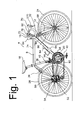
- Fig. 1 is a side view of a bicycle 4.
- Bicycle 4 is a road bicycle comprising a diamond-shaped frame 8, a front fork 12 rotatably mounted to frame 8, a handlebar assembly 16 mounted to the upper part of fork 12, a front wheel 24 rotatably attached to the lower part of fork 12, a rear wheel 28 rotatably attached to the rear of frame 8, a saddle 18 mounted to a seat tube 19 of frame 8, and a drive unit 20.
- a front wheel brake 32 is provided for braking front wheel 24, and a rear wheel brake 36 is provided for braking rear wheel 28.
- Drive unit 20 comprises a chain 60, a front sprocket assembly 44 coaxially mounted with a pedal-operated crank 40, an electrically controlled front derailleur 46 attached to seat tube 19, a rear sprocket assembly 50 coaxially mounted with rear wheel 28, and an electrically controlled rear derailleur 52.
- Front sprocket assembly 44 comprises a plurality of (e.g., two) coaxially mounted sprockets 48
- rear sprocket assembly 50 comprises a plurality of (e.g., eight to ten) sprockets 54.
- Front derailleur 46 moves to a plurality of operating positions to switch chain 60 among front sprockets 48
- rear derailleur 52 moves to a plurality of operating positions to switch chain among selected ones of the rear sprockets 54.
- a handlebar stem 64 is mounted to the upper portion of front fork 12, and a drop-style handlebar 66 is mounted to a front portion of handlebar stem 64.
- a combined brake and shift control device 70 with a gear shift switch 270 mounted behind a brake lever is mounted the right side of handlebar 66.
- a similar combined brake and shift control device 70 is mounted to the left side of handlebar 66.
- the gear shift switches 270 may comprise lever-type switches, for example, and upshift or downshift operations may be performed by moving the switches in different directions.
- the right side brake and shift control device 70 controls the operation of rear brake 36 through a Bowden cable 74
- the left side combined brake and shift control device 70 controls the operation of front brake 107r through a Bowden cable 72.
- Gear shift switch 270 on the right side brake and shift control device 70 controls the operation of rear derailleur 52
- gear shift switch 270 on the left side brake and shift control device 70 controls the operation of front derailleur 46.
- a cycle computer 78 receives electrical gear shift command signals from gear shift switches 270 as well as speed indicating signals from a wheel speed sensor 86 through electrical wiring 90.
- Wheel speed sensor 86 may comprise a reed switch that provides an electrical pulse in response to the passage of a magnet 88 mounted to front wheel 24.
- Cycle computer 78 includes a conventional display for displaying information such as speed and travel distance based on the signals from wheel speed sensor 86.
- Cycle computer 78 communicates control signals for operating front and rear derailleurs 46 and 52 through electrical wiring 84.
- Cycle computer 78 also receives power signals from a power supply 94 through electrical wiring 84.
- Power supply 94 may comprise a replaceable primary or secondary battery.
- rear derailleur 52 includes a base member 100 secured to a rear part 8a of frame 8, a moving mechanism 130 that can move toward or away from rear wheel 28 relative to base member 100, a movable member 104 connected to moving mechanism 130, and a chain guide 108 pivotably connected to movable member 104.
- Base member 100 includes an essentially cylindrical frame mounting unit 170 and a housing unit 174.
- Frame mounting unit 170 includes a bolt mounting opening 178.
- Base member 100 is secured to frame body 8 by a frame mounting bolt 182 that passes through bolt mounting opening 178 such that the rotational position of base member 100 may be adjusted.
- Moving mechanism 130 comprises a first link member 120 and a second link member 124 positioned outside of first link member 120, wherein a first end of each of first link member 120 and second link member 124 is connected to base member 100.
- Link members 120 and 124 are disposed essentially parallel to each other.
- a second end of each first link member 120 and second link member 124 is pivotably connected to movable member 104.
- a biasing member (not shown) comprising a coil spring, for example, is mounted between movable member 104 and chain guide 108 for biasing chain guide 108 clockwise in Fig. 2 in a conventional manner.
- Chain guide 108 rotatably supports a guide pulley 118 and a tension pulley 116, wherein guide pulley 118 guides chain 60 to engage selected ones of the plurality of rear sprockets 54, and tension pulley 116 applies tension to chain 60.
- Housing unit 174 includes a housing member 190 and a cover 194 that is mounted to housing member 190 by screws 198.
- Housing member 190 is integrally formed with frame mounting unit 170.
- Cover 194 preferably is secured to the bottom of housing member 190 so that water and other contaminants do not enter the interior of housing member 190.
- housing member 190 defines a drive mechanism housing space 202 for housing internal components such as a gear shift drive unit 212 and a gear shift control circuit 216 that controls gear shift drive unit 212.
- Gear shift drive unit 212 electrically drives rear derailleur 52 so that chain guide 108 engages chain 60 with any one of the rear sprockets 54.
- gear shift drive unit 212 comprises an electric motor 206 and a speed reduction mechanism 210, wherein motor 206 is disposed to one side of drive mechanism housing space 202.
- Speed reduction mechanism 210 comprises a worm gear (not shown), mounted at the distal end of the rotational shaft of the motor 206, that engages a worm wheel (not shown).
- the worm wheel is integrally formed with a first gear 214, and both components are rotatably supported to a gear support member 220.
- a second gear (not shown) engages with first gear 214, a third gear 230 is integrally formed with this second gear, and both gears are rotatably supported to gear support member 220.
- the speed reduction mechanism 220 can be attached or detached as a single unit by attaching or detaching gear support member 220 to or from housing member 190.
- Third gear 230 engages an output gear 234a of an output shaft unit 234.
- Output shaft unit 234 further comprises a pivot shaft 234b, an intermediate shaft 234c and an output shaft 234d. Pivot shaft 234b is pivotably supported by a recess 190a in housing member 190.
- Intermediate shaft 234c is integrally formed with output gear 234a, and output shaft 234d extends from intermediate shaft 234b to a location outside of housing unit 174.
- Output shaft 234d includes a beveled area (flat) 234e that engages a beveled area (flat) 120a (Fig. 2) on first link member 120 for communicating the rotational force of motor 206 to first link member 120.
- the gear shift control circuit 216 comprises a circuit mounting member 240 that supports various compound electronic circuit elements such microprocessors, memory, other types of LSI chips, and individual electronic circuit elements such as resistors, capacitors, conductive traces, and so on.
- a power storage element 244 such as a large-capacity condenser is mounted to circuit mounting member 240 for storing operating power received from power supply 94 (Fig. 1).
- a through-hole 240a is formed in circuit mounting member 240 for receiving output shaft 234d therethrough, and a rotation position detector circuit element 248 is disposed in close proximity to through-hole 240a.
- rotation position detector circuit element 248 comprises four concentric arc-shaped conductive traces 248a-248d having different radii and lengths.
- Another rotation position detector circuit element 256 in the form of a contact brush 256 is non-rotatably mounted to output shaft 234d through an insulating washer 252.
- Brush 256 has four conductive brush contacts 256a-256d, each of which selectively contacts an associated one of the conductive traces 248a-248d when output shaft 234d is located at different rotational positions.
- the rotational position of output shaft 234d, and hence the gear position of chain guide 108, may be determined by which combination of conductive traces 248a-248d is being contacted by brush contacts 256a-256d. Brush 256 and conductive traces 248a-248d thus form a gear position sensor 260 (Fig. 5).
- circuit mounting member 240 is a one-piece flexible member comprising a pliable synthetic resin that is formed in a bent fashion such that it covers three sides of gear support member 220 and conforms to an inner wall 190b of housing member 190.
- circuit mounting member 240 includes sheet members 240q, 240r, 240s, 240t and 240u that support corresponding electronic circuit elements 240v, 240w, 240x, 240y and 240z, wherein sheet member 240q defines a plane P1, sheet member 240r defines a plane P2, and sheet member 240s defines a plane P3.
- Plane P2 is inclined relative to plane P1, and plane P3 is offset but parallel to plane P1.
- Sheet member 240q is connected to sheet member 240s through sheet member 240t, wherein sheet member 240t is perpendicular to both sheet members 240q and 240s and forms a stepped portion of circuit mounting member 240.
- Sheet member 240u extends perpendicularly downwardly from sheet member 240s and has an arcuate shape such that the surface of sheet member that supports electronic circuit elements 240z faces inner wall 190b of housing member 190.
- circuit mounting member 240 including the varying the position of the various sheet members relative to planes containing electronic circuit elements, motor 206, speed reduction mechanism 212 and gear shift control circuit 216 are disposed within the small drive mechanism housing space 202 in a very compact fashion, even when relatively large circuit elements, such as microprocessors, are used. Since a smaller drive mechanism housing space 202 is needed, the size and weight of the overall derailleur is reduced accordingly.
- Fig. 5 is a schematic block diagram of a particular embodiment of gear shift control circuit 216.
- Gear shift control circuit 216 comprises gear position sensor 260, a gear shift control unit 264 in the form of a microprocessor, and a motor drive circuit 268.
- Gear shift control unit 264 receives upshift and downshift signals from rear gear shift switch 270 and gear position signals from gear position sensor 260.
- Motor drive circuit 268 outputs conventional pulse width modulation (PWM) signals to operate motor 206 based on control signals output from gear shift control unit 264 in accordance with the operation of rear gear shift switch 270.
- PWM pulse width modulation
- Fig. 6 is a flow chart showing the operation of gear shift control unit 264.
- initialization is carried out in step S 1.
- step S2 it is determined whether or not an upshift signal has been received from rear gear shift switch 270. If so, it is then determined in a step S5 whether or not a position indicating signal SH output by gear position sensor 260 indicates that rear derailleur 52 currently is in the tenth gear position. If so, then no further upshifting is possible, the upshift signal is ignored, and the process moves to step S3.
- gear shift control unit 264 provides upshift control signals to motor drive circuit 268, and motor drive circuit 268 provides the appropriate operating signal to motor 206 to rotate output shaft 234d to upshift derailleur 52 by one gear.
- step S3 it is then determined in step S3 whether or not a downshift signal has been received from rear gear shift switch 270. If so, it is then determined in a step S10 whether or not gear position sensor 260 indicates that rear derailleur 52 currently is in the first gear position. If so, then no further downshifting is possible, the downshift signal is ignored, and the process returns to step S2. If derailleur 52 is not in the first gear position, then gear shift control unit 264 provides downshift control signals to motor drive circuit 268, and motor drive circuit 268 provides the appropriate operating signal to motor 206 to rotate output shaft 234d to downshift derailleur 52 by one gear.
- gear shift control circuit 216 was disposed inside rear derailleur 52, many other types of electrical components may be disposed within rear derailleur.
- gear shift control circuit 216 may be placed outside of the derailleur, and the electronic circuitry disposed within housing space 202 may comprises motor drive circuit 268 and/or other circuits.
- housing unit 174 was disposed on base member 100 in the above embodiment, many other configurations are possible.
- a housing unit 374 of a rear derailleur 352 may be disposed on a movable member 304.
- motor 206, gear reduction mechanism 210 and gear shift control circuit 216 may be disposed within drive housing 374, and the other end of first link member 120 is connected to output shaft 234d.
- circuit mounting member 240 was employed in a rear derailleur control mechanism, an appropriate circuit mounting member could be used in a front derailleur control mechanism, a suspension control mechanism, a motor drive pedal assisting mechanism, or some other electrical bicycle component.
- moving mechanism 130 for rear derailleur 52 in the disclosed embodiment comprises a pair of link members 120 and 124, many other moving mechanisms are possible.
- the moving mechanism could comprises a screw shaft that rotates via a motor and nut member mounted to the screw shaft, and the nut member may be connected to the movable member.
- the moving mechanism may have a scissors configuration, and a gas or electric solenoid may be used as an actuator.
Landscapes
- Engineering & Computer Science (AREA)
- Chemical & Material Sciences (AREA)
- Combustion & Propulsion (AREA)
- Transportation (AREA)
- Mechanical Engineering (AREA)
- Gear-Shifting Mechanisms (AREA)
- Automatic Cycles, And Cycles In General (AREA)
- General Details Of Gearings (AREA)
- Steering Devices For Bicycles And Motorcycles (AREA)
- Fittings On The Vehicle Exterior For Carrying Loads, And Devices For Holding Or Mounting Articles (AREA)
Abstract
Description
- The present invention is directed to bicycles and, more particularly, to an apparatus for mounting a bicycle electrical component.
- Recently, bicycles have been equipped with various electrical components used to facilitate the operation of the bicycle. For example, various electrical devices may be used to operate the bicycle transmission or to provide an assisting force to facilitate pedaling the bicycle. See, for example, Japanese Laid-Open Patent Application No. 2004-90915.
- Many bicycles have derailleur operated transmissions. Such transmissions usually include a plurality of front sprockets and a plurality of rear sprockets, wherein the plurality of front sprockets are mounted for rotation coaxially with the pedal cranks, and the plurality of rear sprockets are mounted for rotation coaxially with the rear wheel. A front derailleur is mounted to the bicycle frame in close proximity to the plurality of front sprockets to selectively engage a chain with one of the plurality of front sprockets, and a rear derailleur is mounted to the bicycle frame in close proximity to the plurality of rear sprockets to selectively engage the chain with one of the plurality of rear sprockets.
- Electrical devices have been used to control such derailleur operated transmissions. A typical electrically operated derailleur, for example, comprises a housing member mounted to the bicycle, a drive unit such as a motor disposed in the housing member, a gear shift cable connected between the motor and the derailleur, a gear shift controller disposed in the housing member next to the drive unit for controlling the operation of the motor, and a shift control device typically mounted on the bicycle handlebar for providing gear shift signals. The gear shift signals may be provided automatically in response to bicycle speed or manually in response to the operation of a lever or button by the rider. The gear shift controller usually includes a control unit comprising a programmed microprocessor mounted on a flat circuit substrate such as a printed circuit board. The gear shift controller causes the motor to move the gear shift cable in response to the gear shift signals from the shift control device, thereby moving the derailleur to position the chain on the desired sprocket.
- In a typical electrically controlled device, the control unit mounted to the flat circuit substrate is disposed adjacent to the drive unit in the housing member. As a result, the housing member must be constructed with a housing space large enough to accommodate both the drive unit and the flat circuit substrate. Because the circuit substrate typically has a square or rectangular shape, the housing member often must be made larger than desired, with needless and wasteful space inside the housing member. The larger housing member also makes the electrically operated component larger and heavier. Since the bicycle is powered by human pedaling, the added weight increases the effort required by the rider.
- The present invention is directed to various features of an apparatus for mounting a bicycle electrical component. In one embodiment, an apparatus for mounting a bicycle electrical component comprises a housing member structured to be mounted to a bicycle and an electronic circuit element mounted to a circuit mounting member, wherein the circuit mounting member is disposed in the housing. The circuit mounting member has a shape that varies away from a plane containing the electronic circuit element to conform to a shape of the housing member. Additional inventive features will become apparent from the description below, and such features alone or in combination with the above features may form the basis of further inventions as recited in the claims and their equivalents.
-
- Fig. 1 is a side view of a particular embodiment of a bicycle;
- Fig. 2 is a detailed view of a particular embodiment of a rear derailleur;
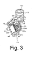
- Fig. 3 is an elevational view of a derailleur base member with the cover removed;
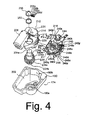
- Fig. 4 is an exploded view of electrical components disposed within a housing member formed by the base member;
- Fig. 5 is a schematic block diagram of a particular embodiment of a gear shift control apparatus;
- Fig. 6 is a flow chart showing the operation of the gear shift control apparatus; and
- Fig. 7 is a detailed view of another embodiment of a rear derailleur.
- Fig. 1 is a side view of a
bicycle 4.Bicycle 4 is a road bicycle comprising a diamond-shaped frame 8, afront fork 12 rotatably mounted toframe 8, a handlebar assembly 16 mounted to the upper part offork 12, afront wheel 24 rotatably attached to the lower part offork 12, arear wheel 28 rotatably attached to the rear offrame 8, asaddle 18 mounted to aseat tube 19 offrame 8, and adrive unit 20. Afront wheel brake 32 is provided for brakingfront wheel 24, and arear wheel brake 36 is provided for brakingrear wheel 28. -
Drive unit 20 comprises achain 60, afront sprocket assembly 44 coaxially mounted with a pedal-operatedcrank 40, an electrically controlledfront derailleur 46 attached toseat tube 19, arear sprocket assembly 50 coaxially mounted withrear wheel 28, and an electrically controlledrear derailleur 52.Front sprocket assembly 44 comprises a plurality of (e.g., two) coaxially mountedsprockets 48, andrear sprocket assembly 50 comprises a plurality of (e.g., eight to ten)sprockets 54.Front derailleur 46 moves to a plurality of operating positions to switchchain 60 amongfront sprockets 48, andrear derailleur 52 moves to a plurality of operating positions to switch chain among selected ones of therear sprockets 54. - A
handlebar stem 64 is mounted to the upper portion offront fork 12, and a drop-style handlebar 66 is mounted to a front portion ofhandlebar stem 64. A combined brake andshift control device 70 with agear shift switch 270 mounted behind a brake lever is mounted the right side ofhandlebar 66. A similar combined brake andshift control device 70 is mounted to the left side ofhandlebar 66. Thegear shift switches 270 may comprise lever-type switches, for example, and upshift or downshift operations may be performed by moving the switches in different directions. The right side brake andshift control device 70 controls the operation ofrear brake 36 through a Bowdencable 74, and the left side combined brake andshift control device 70 controls the operation of front brake 107r through a Bowden cable 72.Gear shift switch 270 on the right side brake andshift control device 70 controls the operation ofrear derailleur 52, andgear shift switch 270 on the left side brake andshift control device 70 controls the operation offront derailleur 46. - A
cycle computer 78 receives electrical gear shift command signals fromgear shift switches 270 as well as speed indicating signals from awheel speed sensor 86 throughelectrical wiring 90.Wheel speed sensor 86 may comprise a reed switch that provides an electrical pulse in response to the passage of amagnet 88 mounted tofront wheel 24.Cycle computer 78 includes a conventional display for displaying information such as speed and travel distance based on the signals fromwheel speed sensor 86.Cycle computer 78 communicates control signals for operating front andrear derailleurs electrical wiring 84.Cycle computer 78 also receives power signals from apower supply 94 throughelectrical wiring 84.Power supply 94 may comprise a replaceable primary or secondary battery. - As shown in Fig. 2,
rear derailleur 52 includes abase member 100 secured to arear part 8a offrame 8, amoving mechanism 130 that can move toward or away fromrear wheel 28 relative tobase member 100, amovable member 104 connected to movingmechanism 130, and achain guide 108 pivotably connected tomovable member 104.Base member 100 includes an essentially cylindricalframe mounting unit 170 and ahousing unit 174.Frame mounting unit 170 includes a bolt mounting opening 178.Base member 100 is secured toframe body 8 by aframe mounting bolt 182 that passes throughbolt mounting opening 178 such that the rotational position ofbase member 100 may be adjusted. -
Moving mechanism 130 comprises afirst link member 120 and asecond link member 124 positioned outside offirst link member 120, wherein a first end of each offirst link member 120 andsecond link member 124 is connected tobase member 100.Link members first link member 120 andsecond link member 124 is pivotably connected tomovable member 104. A biasing member (not shown) comprising a coil spring, for example, is mounted betweenmovable member 104 andchain guide 108 forbiasing chain guide 108 clockwise in Fig. 2 in a conventional manner.Chain guide 108 rotatably supports aguide pulley 118 and atension pulley 116, whereinguide pulley 118guides chain 60 to engage selected ones of the plurality ofrear sprockets 54, andtension pulley 116 applies tension tochain 60. -
Housing unit 174 includes ahousing member 190 and acover 194 that is mounted tohousing member 190 byscrews 198.Housing member 190 is integrally formed withframe mounting unit 170.Cover 194 preferably is secured to the bottom ofhousing member 190 so that water and other contaminants do not enter the interior ofhousing member 190. As shown in Fig. 3,housing member 190 defines a drivemechanism housing space 202 for housing internal components such as a gearshift drive unit 212 and a gearshift control circuit 216 that controls gearshift drive unit 212. Gearshift drive unit 212 electrically drivesrear derailleur 52 so thatchain guide 108 engageschain 60 with any one of therear sprockets 54. - As shown in Fig. 4, gear
shift drive unit 212 comprises anelectric motor 206 and aspeed reduction mechanism 210, whereinmotor 206 is disposed to one side of drivemechanism housing space 202.Speed reduction mechanism 210 comprises a worm gear (not shown), mounted at the distal end of the rotational shaft of themotor 206, that engages a worm wheel (not shown). The worm wheel is integrally formed with afirst gear 214, and both components are rotatably supported to agear support member 220. A second gear (not shown) engages withfirst gear 214, athird gear 230 is integrally formed with this second gear, and both gears are rotatably supported to gearsupport member 220. As a result of the foregoing structure, thespeed reduction mechanism 220 can be attached or detached as a single unit by attaching or detachinggear support member 220 to or fromhousing member 190.Third gear 230 engages anoutput gear 234a of anoutput shaft unit 234.Output shaft unit 234 further comprises apivot shaft 234b, anintermediate shaft 234c and anoutput shaft 234d.Pivot shaft 234b is pivotably supported by arecess 190a inhousing member 190.Intermediate shaft 234c is integrally formed withoutput gear 234a, andoutput shaft 234d extends fromintermediate shaft 234b to a location outside ofhousing unit 174.Output shaft 234d includes a beveled area (flat) 234e that engages a beveled area (flat) 120a (Fig. 2) onfirst link member 120 for communicating the rotational force ofmotor 206 tofirst link member 120. - The gear
shift control circuit 216 comprises acircuit mounting member 240 that supports various compound electronic circuit elements such microprocessors, memory, other types of LSI chips, and individual electronic circuit elements such as resistors, capacitors, conductive traces, and so on. Apower storage element 244 such as a large-capacity condenser is mounted tocircuit mounting member 240 for storing operating power received from power supply 94 (Fig. 1). - A through-hole 240a is formed in
circuit mounting member 240 for receivingoutput shaft 234d therethrough, and a rotation positiondetector circuit element 248 is disposed in close proximity to through-hole 240a. In this embodiment, rotation positiondetector circuit element 248 comprises four concentric arc-shapedconductive traces 248a-248d having different radii and lengths. Another rotation positiondetector circuit element 256 in the form of acontact brush 256 is non-rotatably mounted tooutput shaft 234d through an insulatingwasher 252.Brush 256 has fourconductive brush contacts 256a-256d, each of which selectively contacts an associated one of theconductive traces 248a-248d whenoutput shaft 234d is located at different rotational positions. The rotational position ofoutput shaft 234d, and hence the gear position ofchain guide 108, may be determined by which combination ofconductive traces 248a-248d is being contacted bybrush contacts 256a-256d.Brush 256 andconductive traces 248a-248d thus form a gear position sensor 260 (Fig. 5). - In this embodiment,
circuit mounting member 240 is a one-piece flexible member comprising a pliable synthetic resin that is formed in a bent fashion such that it covers three sides ofgear support member 220 and conforms to aninner wall 190b ofhousing member 190. For example,circuit mounting member 240 includessheet members electronic circuit elements sheet member 240q defines a plane P1,sheet member 240r defines a plane P2, andsheet member 240s defines a plane P3. Plane P2 is inclined relative to plane P1, and plane P3 is offset but parallel to plane P1.Sheet member 240q is connected tosheet member 240s throughsheet member 240t, whereinsheet member 240t is perpendicular to bothsheet members circuit mounting member 240.Sheet member 240u extends perpendicularly downwardly fromsheet member 240s and has an arcuate shape such that the surface of sheet member that supportselectronic circuit elements 240z facesinner wall 190b ofhousing member 190. As a result of the configuration ofcircuit mounting member 240, including the varying the position of the various sheet members relative to planes containing electronic circuit elements,motor 206,speed reduction mechanism 212 and gearshift control circuit 216 are disposed within the small drivemechanism housing space 202 in a very compact fashion, even when relatively large circuit elements, such as microprocessors, are used. Since a smaller drivemechanism housing space 202 is needed, the size and weight of the overall derailleur is reduced accordingly. - Fig. 5 is a schematic block diagram of a particular embodiment of gear
shift control circuit 216. Gearshift control circuit 216 comprisesgear position sensor 260, a gearshift control unit 264 in the form of a microprocessor, and amotor drive circuit 268. Gearshift control unit 264 receives upshift and downshift signals from reargear shift switch 270 and gear position signals fromgear position sensor 260.Motor drive circuit 268 outputs conventional pulse width modulation (PWM) signals to operatemotor 206 based on control signals output from gearshift control unit 264 in accordance with the operation of reargear shift switch 270. - Fig. 6 is a flow chart showing the operation of gear
shift control unit 264. When the power supply to gearshift control unit 264 is turned ON, initialization is carried out instep S 1. In step S2, it is determined whether or not an upshift signal has been received from reargear shift switch 270. If so, it is then determined in a step S5 whether or not a position indicating signal SH output bygear position sensor 260 indicates thatrear derailleur 52 currently is in the tenth gear position. If so, then no further upshifting is possible, the upshift signal is ignored, and the process moves to step S3. Ifderailleur 52 is not in the tenth gear position, then gearshift control unit 264 provides upshift control signals tomotor drive circuit 268, andmotor drive circuit 268 provides the appropriate operating signal tomotor 206 to rotateoutput shaft 234d to upshiftderailleur 52 by one gear. - In any event, it is then determined in step S3 whether or not a downshift signal has been received from rear
gear shift switch 270. If so, it is then determined in a step S10 whether or not gearposition sensor 260 indicates thatrear derailleur 52 currently is in the first gear position. If so, then no further downshifting is possible, the downshift signal is ignored, and the process returns to step S2. Ifderailleur 52 is not in the first gear position, then gearshift control unit 264 provides downshift control signals tomotor drive circuit 268, andmotor drive circuit 268 provides the appropriate operating signal tomotor 206 to rotateoutput shaft 234d to downshiftderailleur 52 by one gear. - While the above is a description of various embodiments of inventive features, further modifications may be employed without departing from the spirit and scope of the present invention. For example, while a gear
shift control circuit 216 was disposed insiderear derailleur 52, many other types of electrical components may be disposed within rear derailleur. For example, gearshift control circuit 216 may be placed outside of the derailleur, and the electronic circuitry disposed withinhousing space 202 may comprisesmotor drive circuit 268 and/or other circuits. - While
housing unit 174 was disposed onbase member 100 in the above embodiment, many other configurations are possible. For example, as shown in Fig. 7, ahousing unit 374 of arear derailleur 352 may be disposed on amovable member 304. In this embodiment,motor 206,gear reduction mechanism 210 and gearshift control circuit 216 may be disposed withindrive housing 374, and the other end offirst link member 120 is connected tooutput shaft 234d. - While
circuit mounting member 240 was employed in a rear derailleur control mechanism, an appropriate circuit mounting member could be used in a front derailleur control mechanism, a suspension control mechanism, a motor drive pedal assisting mechanism, or some other electrical bicycle component. While movingmechanism 130 forrear derailleur 52 in the disclosed embodiment comprises a pair oflink members - The size, shape, location or orientation of the various components may be changed as desired. Components that are shown directly connected or contacting each other may have intermediate structures disposed between them. The functions of one element may be performed by two, and vice versa. The structures and functions of one embodiment may be adopted in another embodiment. It is not necessary for all advantages to be present in a particular embodiment at the same time. Every feature which is unique from the prior art, alone or in combination with other features, also should be considered a separate description of further inventions by the applicant, including the structural and/or functional concepts embodied by such feature(s). Thus, the scope of the invention should not be limited by the specific structures disclosed or the apparent initial focus or emphasis on a particular structure or feature.
Claims (21)
- An apparatus for mounting a bicycle electrical component comprising:a housing member (190) structured to be mounted to a bicycle;an electronic circuit element (240v, 240w, 240x, 240y, 240z) mounted to a circuit mounting member (240) , wherein the circuit mounting member (240) is disposed in the housing member (190); andwherein the circuit mounting member (240) has a shape that varies away from a plane containing the electronic circuit element (240v, 240w, 240x, 240y, 240z) to conform to a shape of the housing member (190).
- The apparatus according to claim 1 wherein the circuit mounting member (240) has a flexible portion.
- The apparatus according to claim 2 wherein at least a part of the flexible portion covers an inner wall of the housing member (190).
- The apparatus according to claim 1 further comprising an internal component disposed within the housing member (190), wherein the internal component is separate from the electronic circuit element (240v, 240w, 240x, 240y, 240z).
- The apparatus according to claim 4 wherein the internal component comprises a gear shift drive unit (212) that electrically drives a bicycle gear shift apparatus for a bicycle transmission.
- The apparatus according to claim 4 wherein the internal component comprises a motor (206).
- The apparatus according to claim 6 wherein the internal component further comprises a gear reduction mechanism (210) coupled to the motor (206).
- The apparatus according to claim 6 further comprising an output shaft (234d) that communicates rotational force from the motor (206) to a location outside the housing member (190).
- The apparatus according to claim 8 wherein the circuit mounting member (240) has a through-hole (240a) through which the output shaft (234d) passes.
- The apparatus according to claim 9 wherein the electronic circuit element (240v, 240w, 240x, 240y, 240z) includes a rotation position detector circuit element (248) disposed in close proximity to the through-hole (240a).
- The apparatus according to claim 1 wherein the circuit mounting member (240) comprises:a first sheet member (240q); anda second sheet member (240r);wherein the first sheet member (240q) is inclined relative to the second sheet member (240r).
- The apparatus according to claim 11 wherein the first sheet member (240q) has the electronic circuit element (240) mounted thereon.
- The apparatus according to claim 12 wherein the second sheet member (240r) has a second electronic circuit element (240w) mounted thereon.
- The apparatus according to claim 1 wherein the circuit mounting member (240) comprises:a first sheet member (240q); anda second sheet member (240s);wherein a first plane (P1) of the first sheet member (240q) is offset from a second plane (P3) of the second sheet member (240s).
- The apparatus according to claim 14 wherein the first plane (P1) is substantially parallel to the second plane (P3).
- The apparatus according to claim 15 wherein the circuit mounting member (240) further comprises a third sheet member connected to and forming a step between the first sheet member (240q) and the second sheet member (240r).
- The apparatus according to claim 16 wherein the first sheet member (240q) has the first electronic circuit element (240v) mounted thereon.
- The apparatus according to claim 17 wherein the second sheet member (240s) has a second electronic circuit element (240x) mounted thereon.
- A bicycle derailleur (52) comprising:a base member (100) structured to be mounted to a bicycle frame (8);a movable member (104);a moving mechanism (130) coupled between the base member (100) and the movable member (104) so that the movable member (104) moves relative to the base member (100);a chain guide (108) coupled to the movable member (104);a housing member (190) disposed on one of the base member (100) and the movable member (104);an electronic circuit element (240v, 240w, 240x, 240y, 240z) mounted to a circuit mounting member (240), wherein the circuit mounting member (240) is disposed in the housing member (190); andwherein the circuit mounting member (240) has a shape that varies away from a plane containing the electronic circuit element (240v, 240w, 240x, 240y, 240z) to conform to a shape of the housing member (190).
- The derailleur according to claim 19 further comprising:a motor (206) disposed in the housing member (190); andan output shaft (234d) that communicates rotational force from the motor (206) to a location outside of the housing member (190).
- The derailleur according to claim 20 wherein the moving mechanism (130) comprises:a first link member (120) having a first end coupled to the output shaft (234d) and a second end pivotably coupled to the movable member (104); anda second link member (124) having a first end pivotably coupled to the base member (100) and a second end pivotably coupled to the movable member (104);wherein rotational force from the motor (206) is communicated through the output shaft (234d) to the first link member (120) so that the movable member (104) moves relative to the base member (100).
Applications Claiming Priority (1)
| Application Number | Priority Date | Filing Date | Title |
|---|---|---|---|
| JP2004325829A JP2006137206A (en) | 2004-11-10 | 2004-11-10 | Electrical component for bicycle and derailleur for bicycle using the same |
Publications (3)
| Publication Number | Publication Date |
|---|---|
| EP1657154A2 true EP1657154A2 (en) | 2006-05-17 |
| EP1657154A3 EP1657154A3 (en) | 2008-09-17 |
| EP1657154B1 EP1657154B1 (en) | 2010-01-06 |
Family
ID=35376997
Family Applications (1)
| Application Number | Title | Priority Date | Filing Date |
|---|---|---|---|
| EP05024296A Expired - Lifetime EP1657154B1 (en) | 2004-11-10 | 2005-11-08 | Apparatus for mounting a bicycle electrical component |
Country Status (7)
| Country | Link |
|---|---|
| US (1) | US7980974B2 (en) |
| EP (1) | EP1657154B1 (en) |
| JP (1) | JP2006137206A (en) |
| CN (1) | CN100441475C (en) |
| BR (1) | BRPI0505062A (en) |
| DE (1) | DE602005018731D1 (en) |
| TW (1) | TWI285175B (en) |
Cited By (1)
| Publication number | Priority date | Publication date | Assignee | Title |
|---|---|---|---|---|
| EP3483053A1 (en) * | 2017-11-09 | 2019-05-15 | SRAM Deutschland GmbH | Electromechanical switch mechanism |
Families Citing this family (45)
| Publication number | Priority date | Publication date | Assignee | Title |
|---|---|---|---|---|
| US7467567B2 (en) * | 2004-02-24 | 2008-12-23 | Shimano, Inc. | Gear reduction apparatus for a bicycle component |
| US8137223B2 (en) * | 2007-05-16 | 2012-03-20 | Shimano Inc. | Bicycle rear derailleur |
| JP4135161B2 (en) | 2007-07-14 | 2008-08-20 | 公二 宇野 | Bicycle brake operating device |
| JP5422127B2 (en) * | 2008-01-23 | 2014-02-19 | 本田技研工業株式会社 | Motorcycle |
| KR100966120B1 (en) * | 2009-12-28 | 2010-06-25 | 이창용 | Automatic transmission gear box of bicycle |
| US20120035011A1 (en) * | 2010-08-09 | 2012-02-09 | Menachem Haim | Electro mechanical bicycle derailleur actuator system and method |
| TW201226259A (en) * | 2010-12-31 | 2012-07-01 | J D Components Co Ltd | Pedaling assistance power supply system of a bicycle |
| US10207772B2 (en) * | 2011-01-28 | 2019-02-19 | Paha Designs, Llc | Gear transmission and derailleur system |
| US9327792B2 (en) * | 2011-01-28 | 2016-05-03 | Paha Designs, Llc | Gear transmission and derailleur system |
| TW201300278A (en) * | 2011-06-23 | 2013-01-01 | J D Components Co Ltd | Speed change mechanism of an electric bicycle |
| US8900078B2 (en) | 2011-10-05 | 2014-12-02 | Shimano Inc. | Bicycle derailleur |
| US8979683B2 (en) * | 2012-01-31 | 2015-03-17 | Shimano Inc. | Bicycle electric actuator unit |
| DE102012204908B4 (en) * | 2012-03-27 | 2018-08-02 | Brose Fahrzeugteile Gmbh & Co. Kommanditgesellschaft, Coburg | Electric bicycle with a hybrid drive |
| US9394030B2 (en) * | 2012-09-27 | 2016-07-19 | Sram, Llc | Rear derailleur |
| JP2014091384A (en) * | 2012-11-01 | 2014-05-19 | Shimano Inc | Motor unit for driving bicycle transmission |
| US8882618B2 (en) * | 2013-01-29 | 2014-11-11 | Shimano Inc. | Rear derailleur |
| US9005059B2 (en) * | 2013-03-27 | 2015-04-14 | Shimano Inc. | Rear derailleur |
| US9290235B2 (en) | 2013-06-18 | 2016-03-22 | Shimano Inc. | Bicycle derailleur |
| US9676444B2 (en) * | 2013-10-23 | 2017-06-13 | Sram, Llc | Electromechanical rear derailleur |
| US10155567B2 (en) * | 2014-10-07 | 2018-12-18 | Shimano Inc. | Bicycle shifting control apparatus |
| US10370060B2 (en) * | 2015-10-30 | 2019-08-06 | Shimano Inc. | Bicycle electrical component assembly |
| US20170066501A1 (en) * | 2015-09-08 | 2017-03-09 | Praxis Works LLC | Belt-aligned derailleur |
| US9873482B2 (en) * | 2015-10-09 | 2018-01-23 | Shimano Inc. | Bicycle front derailleur |
| US9656723B1 (en) * | 2015-12-14 | 2017-05-23 | Shimano Inc. | Electrical bicycle derailleur |
| CN107284600A (en) * | 2016-03-31 | 2017-10-24 | 天心工业股份有限公司 | Electric front chain shifter |
| IT201600069087A1 (en) * | 2016-07-04 | 2018-01-04 | Campagnolo Srl | Front electric bicycle derailleur |
| US10556639B2 (en) * | 2016-09-13 | 2020-02-11 | Brandon Rodgers | Wireless sprocket shifting control system |
| IT201700035716A1 (en) * | 2017-03-31 | 2018-10-01 | Campagnolo Srl | Bicycle rear derailleur |
| US10773773B2 (en) | 2017-06-07 | 2020-09-15 | Shimano Inc. | Electric bicycle derailleur |
| US11110993B2 (en) * | 2017-09-13 | 2021-09-07 | Brandon Rodgers | Damping device adapted for integration within a gearshifting system |
| US10981625B2 (en) * | 2017-10-02 | 2021-04-20 | Sram, Llc | Bicycle rear derailleur |
| TWM562815U (en) * | 2018-04-03 | 2018-07-01 | 彥豪金屬工業股份有限公司 | Derailleur assembly |
| IT201800009245A1 (en) * | 2018-10-08 | 2020-04-08 | Campagnolo Srl | Bicycle shifting with high control precision and method for making a shift in a bicycle shift |
| WO2020124280A1 (en) * | 2018-12-20 | 2020-06-25 | 郑仲瑞 | Integrated automatic rear derailleur of bicycle |
| US11498643B2 (en) * | 2019-02-26 | 2022-11-15 | Shimano Inc. | Bicycle electric derailleur |
| US11608139B2 (en) * | 2019-05-13 | 2023-03-21 | Shimano Inc. | Bicycle rear derailleur |
| US11535339B2 (en) * | 2019-08-30 | 2022-12-27 | Shimano Inc. | Bicycle derailleur |
| TWI712547B (en) * | 2019-11-06 | 2020-12-11 | 天心工業股份有限公司 | Rear derailleur |
| US11697474B2 (en) * | 2020-06-30 | 2023-07-11 | Shimano Inc. | Bicycle derailleur and link pin for bicycle derailleur |
| US11745828B2 (en) * | 2020-06-30 | 2023-09-05 | Shimano Inc. | Front derailleur and chain guide of bicycle derailleur |
| US11565772B2 (en) * | 2020-06-30 | 2023-01-31 | Shimano Inc. | Bicycle derailleur, bicycle gear structure, bicycle motor unit, and front derailleur |
| US11897573B2 (en) * | 2020-08-26 | 2024-02-13 | Shimano Inc. | Operating device for human-powered vehicle |
| US11685469B2 (en) * | 2020-09-11 | 2023-06-27 | Shimano Inc. | Bicycle derailleur |
| US11981398B2 (en) * | 2020-09-11 | 2024-05-14 | Shimano Inc. | Bicycle derailleur |
| JP7624344B2 (en) * | 2021-04-30 | 2025-01-30 | 株式会社シマノ | Control device, control system, control method and computer program for human-powered vehicle |
Citations (1)
| Publication number | Priority date | Publication date | Assignee | Title |
|---|---|---|---|---|
| JP2004090915A (en) | 2002-08-29 | 2004-03-25 | Shimano Inc | Auxiliary device motor unit for bicycle transmission |
Family Cites Families (44)
| Publication number | Priority date | Publication date | Assignee | Title |
|---|---|---|---|---|
| US3919891A (en) * | 1973-10-15 | 1975-11-18 | Brian J Stuhlmuller | Electrical gear changer for chain driven vehicle |
| US3863512A (en) * | 1973-11-09 | 1975-02-04 | California Progressive Prod | Shift mechanism for derailleur drive |
| US4041788A (en) * | 1975-07-30 | 1977-08-16 | California Progressive Products, Inc. | Electrical control for derailleur drive |
| JPS5438041A (en) | 1977-09-01 | 1979-03-22 | Sekine Indasutoriizu Kk | Automatic speed change gear in bicycle |
| US4567543A (en) * | 1983-02-15 | 1986-01-28 | Motorola, Inc. | Double-sided flexible electronic circuit module |
| US4605240A (en) * | 1983-08-18 | 1986-08-12 | Telewe', Inc. | Electronically controlled bicycle transmission |
| DE3631481A1 (en) * | 1986-09-16 | 1988-05-05 | Villiger Soehne Ag | ELECTROMECHANICAL BICYCLE GEAR |
| US4952196A (en) * | 1987-10-21 | 1990-08-28 | Autra-Bike Co., Inc. | Variable diameter sprocket assembly |
| US4928206A (en) * | 1988-11-23 | 1990-05-22 | Ncr Corporation | Foldable printed circuit board |
| US5193895A (en) * | 1990-01-18 | 1993-03-16 | Koito Manufacturing Co., Ltd. | Warning light |
| US5059158A (en) * | 1990-05-08 | 1991-10-22 | E.B.T., Inc. | Electronic transmission control system for a bicycle |
| US5177432A (en) * | 1991-05-31 | 1993-01-05 | Ppg Industries, Inc. | Wireless velocity detector for a bicycle having a rotating AC magnetic field and receiver coils |
| DE4128866A1 (en) | 1991-08-30 | 1993-03-04 | Fichtel & Sachs Ag | ELECTROMECHANICAL GEAR SHIFT FOR BICYCLES |
| IT1252263B (en) * | 1991-11-18 | 1995-06-08 | Catene Calibrate Regina | ELECTROMECHANICAL GEARBOX FOR BICYCLE |
| FR2687977B1 (en) * | 1992-02-27 | 1994-04-22 | Bg Innovation | DEVICES ALLOWING THE CHANGES OF SPEEDS ON BICYCLES. |
| US5213548A (en) * | 1992-03-02 | 1993-05-25 | Colbert Ralph G | Gear shifting system for derailleur equipped bicycle |
| JP2617059B2 (en) | 1992-03-18 | 1997-06-04 | ブリヂストンサイクル株式会社 | Electric transmission for bicycle |
| DE4212319A1 (en) * | 1992-04-13 | 1993-10-14 | Fichtel & Sachs Ag | control device |
| DE4212320A1 (en) * | 1992-04-13 | 1993-10-14 | Fichtel & Sachs Ag | Electric actuator |
| JPH05319357A (en) | 1992-05-25 | 1993-12-03 | Yamaha Motor Co Ltd | Electric transmission for bicycle |
| JPH0648368A (en) | 1992-07-27 | 1994-02-22 | Yamaha Motor Co Ltd | Motor-driven transmission for bicycle |
| IT1261090B (en) * | 1993-07-08 | 1996-05-08 | Antonio Romano | MOTORIZED SPEED CHANGE UNIT FOR BICYCLES. |
| IT1266817B1 (en) * | 1994-02-24 | 1997-01-21 | Campagnolo Srl | SPEED CHANGE DEVICE FOR BICYCLES. |
| US5599244A (en) * | 1995-08-14 | 1997-02-04 | Ethington; Russell A. | Automatic transmission shifter for velocipedes |
| US5873283A (en) * | 1997-01-14 | 1999-02-23 | Chen; Cheng Hsiung | Motorized control for a derailleur |
| FR2769574B1 (en) * | 1997-10-10 | 1999-12-31 | Mavic Sa | LIQUID CRYSTAL DISPLAY DEVICE FOR A BICYCLE |
| JPH11124072A (en) * | 1997-10-22 | 1999-05-11 | Honda Motor Co Ltd | Electric assisted bicycle |
| CN2317166Y (en) * | 1997-10-28 | 1999-05-05 | 洪进廉 | Improved front wheel driving structure for electric bicycle |
| US5903440A (en) * | 1998-01-30 | 1999-05-11 | Delco Electronics Corporaiton | Method of forming assemblies of circuit boards in different planes |
| CN2330573Y (en) * | 1998-05-19 | 1999-07-28 | 捷安特(中国)有限公司 | Electric bicycle control handbar |
| CN2352436Y (en) * | 1998-07-23 | 1999-12-08 | 青松科技股份有限公司 | Auxiliary Mechanism of Electric Bicycle |
| US6162140A (en) * | 1998-12-18 | 2000-12-19 | Shimano, Inc. | Motor driven derailleur |
| IT1310731B1 (en) * | 1999-11-23 | 2002-02-22 | Campagnolo Srl | SPEED CHANGE DEVICE FOR BICYCLES. |
| JP2002098225A (en) * | 2000-09-22 | 2002-04-05 | Hosiden Corp | Transmission control device |
| US6842325B2 (en) * | 2001-09-19 | 2005-01-11 | Square D Company | Flexible circuit adhered to metal frame of device |
| US6726586B2 (en) * | 2001-11-09 | 2004-04-27 | Shimano Inc. | Motorized bicycle actuator assembly |
| US20030106974A1 (en) * | 2001-12-06 | 2003-06-12 | Guertin Jeffery W. | Apparatus and method for mounting accessories to a motorcycle |
| KR100454934B1 (en) | 2001-12-10 | 2004-11-06 | 삼성전자주식회사 | Dual lcd mounting device of mobile phone |
| JP2003215233A (en) * | 2002-01-24 | 2003-07-30 | Murata Mfg Co Ltd | Radar head module |
| US6945888B2 (en) * | 2002-11-21 | 2005-09-20 | Shimano, Inc. | Combined analog and digital derailleur position processing apparatus |
| US6997835B2 (en) * | 2002-11-26 | 2006-02-14 | Shimano, Inc. | Electrically operated derailleur with power storing mechanism |
| JP3793143B2 (en) * | 2002-11-28 | 2006-07-05 | 株式会社シマノ | Bicycle electronic control device |
| US7170748B2 (en) * | 2003-07-24 | 2007-01-30 | Schweltzer Engineering Laboratories, Inc. | Heat sink assembly for integrated circuits having a slidable contact capability with a mounting member portion of an electronic equipment chassis |
| US20050197222A1 (en) * | 2004-03-08 | 2005-09-08 | Shimano Inc. | Front derailleur motor unit assembly |
-
2004
- 2004-11-10 JP JP2004325829A patent/JP2006137206A/en active Pending
-
2005
- 2005-09-13 US US11/162,507 patent/US7980974B2/en not_active Expired - Fee Related
- 2005-09-15 TW TW094131883A patent/TWI285175B/en not_active IP Right Cessation
- 2005-11-08 EP EP05024296A patent/EP1657154B1/en not_active Expired - Lifetime
- 2005-11-08 DE DE602005018731T patent/DE602005018731D1/en not_active Expired - Lifetime
- 2005-11-09 BR BRPI0505062-6A patent/BRPI0505062A/en not_active IP Right Cessation
- 2005-11-10 CN CNB2005101194452A patent/CN100441475C/en not_active Expired - Lifetime
Patent Citations (1)
| Publication number | Priority date | Publication date | Assignee | Title |
|---|---|---|---|---|
| JP2004090915A (en) | 2002-08-29 | 2004-03-25 | Shimano Inc | Auxiliary device motor unit for bicycle transmission |
Cited By (3)
| Publication number | Priority date | Publication date | Assignee | Title |
|---|---|---|---|---|
| EP3483053A1 (en) * | 2017-11-09 | 2019-05-15 | SRAM Deutschland GmbH | Electromechanical switch mechanism |
| US11565771B2 (en) | 2017-11-09 | 2023-01-31 | Sram Deutschland Gmbh | Electromechanical derailleur |
| EP4509395A1 (en) * | 2017-11-09 | 2025-02-19 | SRAM Deutschland GmbH | Electromechanical switching device |
Also Published As
| Publication number | Publication date |
|---|---|
| DE602005018731D1 (en) | 2010-02-25 |
| JP2006137206A (en) | 2006-06-01 |
| TW200615196A (en) | 2006-05-16 |
| CN100441475C (en) | 2008-12-10 |
| EP1657154B1 (en) | 2010-01-06 |
| US20060100045A1 (en) | 2006-05-11 |
| US7980974B2 (en) | 2011-07-19 |
| BRPI0505062A (en) | 2006-07-04 |
| EP1657154A3 (en) | 2008-09-17 |
| TWI285175B (en) | 2007-08-11 |
| CN1772559A (en) | 2006-05-17 |
Similar Documents
| Publication | Publication Date | Title |
|---|---|---|
| EP1657154B1 (en) | Apparatus for mounting a bicycle electrical component | |
| EP1690784A2 (en) | Apparatus for inhibiting undesirable movement of a bicycle electrical component | |
| US12523277B2 (en) | Front gear changer | |
| US6734376B2 (en) | Electrical switch device for bicycle | |
| EP1568594B1 (en) | Electric derailleur motor unit | |
| EP1568588B1 (en) | Motorized front derailleur mounting member | |
| CN100381330C (en) | Motorized front derailleur assembly with protective structure | |
| US6979009B2 (en) | Motorized bicycle derailleur assembly | |
| US8241158B2 (en) | Bicycle derailleur apparatus with a supported power supply | |
| EP1588934B1 (en) | Electrically controlled bicycle transmission | |
| USRE41782E1 (en) | Electrically operated derailleur with power storing mechanism | |
| US20030207732A1 (en) | Method and apparatus for controlling a bicycle transmission | |
| US20050280244A1 (en) | Bicycle control apparatus mountable in a seat tube | |
| EP1520777B1 (en) | Electronic control device for bicycle | |
| US20060046883A1 (en) | Bicycle power supply mounting apparatus |
Legal Events
| Date | Code | Title | Description |
|---|---|---|---|
| PUAI | Public reference made under article 153(3) epc to a published international application that has entered the european phase |
Free format text: ORIGINAL CODE: 0009012 |
|
| AK | Designated contracting states |
Kind code of ref document: A2 Designated state(s): AT BE BG CH CY CZ DE DK EE ES FI FR GB GR HU IE IS IT LI LT LU LV MC NL PL PT RO SE SI SK TR |
|
| AX | Request for extension of the european patent |
Extension state: AL BA HR MK YU |
|
| RAP1 | Party data changed (applicant data changed or rights of an application transferred) |
Owner name: SHIMANO INC. |
|
| PUAL | Search report despatched |
Free format text: ORIGINAL CODE: 0009013 |
|
| AK | Designated contracting states |
Kind code of ref document: A3 Designated state(s): AT BE BG CH CY CZ DE DK EE ES FI FR GB GR HU IE IS IT LI LT LU LV MC NL PL PT RO SE SI SK TR |
|
| AX | Request for extension of the european patent |
Extension state: AL BA HR MK YU |
|
| 17P | Request for examination filed |
Effective date: 20081020 |
|
| 17Q | First examination report despatched |
Effective date: 20081125 |
|
| AKX | Designation fees paid |
Designated state(s): DE FR IT NL |
|
| GRAP | Despatch of communication of intention to grant a patent |
Free format text: ORIGINAL CODE: EPIDOSNIGR1 |
|
| GRAS | Grant fee paid |
Free format text: ORIGINAL CODE: EPIDOSNIGR3 |
|
| GRAA | (expected) grant |
Free format text: ORIGINAL CODE: 0009210 |
|
| AK | Designated contracting states |
Kind code of ref document: B1 Designated state(s): DE FR IT NL |
|
| REF | Corresponds to: |
Ref document number: 602005018731 Country of ref document: DE Date of ref document: 20100225 Kind code of ref document: P |
|
| REG | Reference to a national code |
Ref country code: NL Ref legal event code: T3 |
|
| PLBE | No opposition filed within time limit |
Free format text: ORIGINAL CODE: 0009261 |
|
| STAA | Information on the status of an ep patent application or granted ep patent |
Free format text: STATUS: NO OPPOSITION FILED WITHIN TIME LIMIT |
|
| 26N | No opposition filed |
Effective date: 20101007 |
|
| REG | Reference to a national code |
Ref country code: DE Ref legal event code: R008 Ref document number: 602005018731 Country of ref document: DE |
|
| REG | Reference to a national code |
Ref country code: DE Ref legal event code: R039 Ref document number: 602005018731 Country of ref document: DE Effective date: 20131206 |
|
| REG | Reference to a national code |
Ref country code: FR Ref legal event code: PLFP Year of fee payment: 11 |
|
| PGFP | Annual fee paid to national office [announced via postgrant information from national office to epo] |
Ref country code: FR Payment date: 20151008 Year of fee payment: 11 Ref country code: NL Payment date: 20151012 Year of fee payment: 11 |
|
| PGFP | Annual fee paid to national office [announced via postgrant information from national office to epo] |
Ref country code: IT Payment date: 20161122 Year of fee payment: 12 |
|
| REG | Reference to a national code |
Ref country code: NL Ref legal event code: MM Effective date: 20161201 |
|
| REG | Reference to a national code |
Ref country code: FR Ref legal event code: ST Effective date: 20170731 |
|
| PG25 | Lapsed in a contracting state [announced via postgrant information from national office to epo] |
Ref country code: NL Free format text: LAPSE BECAUSE OF NON-PAYMENT OF DUE FEES Effective date: 20161201 |
|
| PG25 | Lapsed in a contracting state [announced via postgrant information from national office to epo] |
Ref country code: FR Free format text: LAPSE BECAUSE OF NON-PAYMENT OF DUE FEES Effective date: 20161130 |
|
| PG25 | Lapsed in a contracting state [announced via postgrant information from national office to epo] |
Ref country code: IT Free format text: LAPSE BECAUSE OF NON-PAYMENT OF DUE FEES Effective date: 20171108 |
|
| REG | Reference to a national code |
Ref country code: DE Ref legal event code: R040 Ref document number: 602005018731 Country of ref document: DE |
|
| P01 | Opt-out of the competence of the unified patent court (upc) registered |
Effective date: 20230428 |
|
| PGFP | Annual fee paid to national office [announced via postgrant information from national office to epo] |
Ref country code: DE Payment date: 20241001 Year of fee payment: 20 |
|
| REG | Reference to a national code |
Ref country code: DE Ref legal event code: R071 Ref document number: 602005018731 Country of ref document: DE |