EP1657152A1 - Saddle-riding type vehicle - Google Patents
Saddle-riding type vehicle Download PDFInfo
- Publication number
- EP1657152A1 EP1657152A1 EP04771146A EP04771146A EP1657152A1 EP 1657152 A1 EP1657152 A1 EP 1657152A1 EP 04771146 A EP04771146 A EP 04771146A EP 04771146 A EP04771146 A EP 04771146A EP 1657152 A1 EP1657152 A1 EP 1657152A1
- Authority
- EP
- European Patent Office
- Prior art keywords
- frames
- sub
- main frame
- saddle
- type vehicle
- Prior art date
- Legal status (The legal status is an assumption and is not a legal conclusion. Google has not performed a legal analysis and makes no representation as to the accuracy of the status listed.)
- Granted
Links
Images


Classifications
-
- B—PERFORMING OPERATIONS; TRANSPORTING
- B62—LAND VEHICLES FOR TRAVELLING OTHERWISE THAN ON RAILS
- B62K—CYCLES; CYCLE FRAMES; CYCLE STEERING DEVICES; RIDER-OPERATED TERMINAL CONTROLS SPECIALLY ADAPTED FOR CYCLES; CYCLE AXLE SUSPENSIONS; CYCLE SIDECARS, FORECARS, OR THE LIKE
- B62K11/00—Motorcycles, engine-assisted cycles or motor scooters with one or two wheels
- B62K11/02—Frames
- B62K11/04—Frames characterised by the engine being between front and rear wheels
-
- B—PERFORMING OPERATIONS; TRANSPORTING
- B62—LAND VEHICLES FOR TRAVELLING OTHERWISE THAN ON RAILS
- B62K—CYCLES; CYCLE FRAMES; CYCLE STEERING DEVICES; RIDER-OPERATED TERMINAL CONTROLS SPECIALLY ADAPTED FOR CYCLES; CYCLE AXLE SUSPENSIONS; CYCLE SIDECARS, FORECARS, OR THE LIKE
- B62K2202/00—Motorised scooters
Definitions
- the invention relates to a saddle-riding type vehicle such as a motorcycle.
- a saddle-riding type vehicle including a head pipe that supports a steering handle to be capable of moving rotationally, a frame that extends obliquely downward to the rear from the head pipe, and an engine supported by the frame in a suspended state.
- a saddle-riding type vehicle of this type for example, motorcycles disclosed in Patent Documents 1 to 3 described below are known.
- the motorcycle disclosed in the Patent Document 1 includes a head pipe and a pair of left and right main frames that extend obliquely downward to the rear from the head pipe. Brackets are coupled to rear portions of the main frames. An engine is supported by the left and the right main frames and brackets in a suspended state.
- the motorcycle also includes rear swing arms that support a rear wheel. The rear swing arms are supported by the brackets via a pivot shaft to move up and down freely.
- Patent Document 1 JP-A-08-067285
- the engine is supported by the pair of left and right main frames and brackets in an upper part and a rear part of a crankcase of the engine. Consequently, the main frames and the brackets are required to have rigidity that is large to some extent. Therefore, in order to secure rigidity of the main frames and the brackets, it is necessary to increase thickness of the main frames and the brackets. However, when thickness of the main frames and the like is increased, it is difficult to reduce weight of the body frame.
- both the engine and the rear swing arms are held between the pair of left and right brackets. Consequently, an interval between the left and the right brackets is increased and the main frame sticks out in the left to right direction. Therefore, it is difficult to reduce width of the vehicle (a reduction in width in a vehicle width direction).
- a saddle-riding type vehicle includes: a head pipe that supports a steering shaft to rotationally move freely; a body frame including a main frame that is connected to the head pipe and extends obliquely downward to the rear and a pair of left and right sub-frames that are connected to the main frame and extend obliquely downward to the rear; and a motor supported by the main frame and the respective sub-frames in a suspended state.
- the motor is supported by the main frame and both the sub-frames, whereby the motor is arranged to be laid over the main frame and both the left and the right sub-frames.
- the main frame and the sub-frames are reinforced by the motor, it is possible to keep strength of the main frame itself or the sub-frames themselves low because of reinforcement by the motor. Therefore, it is possible to realize a reduction in a size or a reduction in weight of the body frame while maintaining strength of the body frame.
- a connecting portion of the main frame and the sub-frames is located ahead of a portion supporting the motor in the main frame.
- a portion between a front end portion of the main frame and a portion supporting the motor is reinforced by the sub-frames.
- strength of the main frame is improved.
- a necessary strength distribution of the main frame differs for each vehicle.
- the head pipe is connected to a front end side of the main frame and a cross sectional area of the main frame changes along a longitudinal direction of the main frame such that the front end side is larger than a rear end side.
- the change in the cross sectional area of the main frame may be continuous or stepwise along the longitudinal direction of the main frame.
- a form of the change in the cross sectional area is not specifically limited.
- the main frame is formed relatively thick on the front end side connected to the head pipe.
- the rear end of the main frame is formed relatively thin, when a body cover on a front side of the seat is arranged above the rear end of the main frame, it is possible to keep the body cover low.
- the main frame supports the motor at the rear end of the main frame.
- sub-frames are bent convexly downward and support the motor at least in one place near bent portions.
- the motor functions as a reinforcing member to increase strength of the bent portions of the sub-frames. Since the strength of the sub-frames increases, it is possible to realize a reduction in a size or a reduction in weight of the sub-frames. Since it is possible to reduce a size of the sub-frames, it is possible to keep the body cover on the front side of the seat low.
- the sub-frames are bent convexly downward and support the motor at least in one place further on a rear side than the bent portions.
- the motor functions as a reinforcing member and strength in portions further on the rear side of the bent portions in the sub-frames increases. Since the strength of the sub-frames increases, it is possible to realize a reduction in a size and a reduction in weight of the sub-frames. Since it is possible to reduce a size of the sub-frames, it is possible to keep the body cover on the front side of the seat low.
- the saddle-riding type vehicle includes: a rear wheel; and rear arms that support the rear wheel and extend substantially in a front to rear direction, the sub-frame is bent convexly downward, and both a part of the motor and the rear arms are supported at the rear ends of the sub-frames.
- the sub-frames are bent convexly downward and the saddle-riding type vehicle further includes rear side frames that are connected to a portion further on the rear side than the bent portions of the sub-frames and extend obliquely upward to the rear.
- the rear side portions of the sub-frames are reinforced by the rear side frames. It is possible to reduce a size of the sub-frames because the sub-frames are reinforced. Thus, it is possible to keep the body cover on the front side of the seat low.
- the saddle-riding type vehicle may include plural rear side frames that are connected to the rear ends of the sub-frames, respectively, to extend obliquely upward to the rear and are connected to one another.
- the rear side portions of the sub-frames are reinforced by the plural rear side frames connected to one another.
- strength of the sub-frames increases. Therefore, it is possible to realize a reduction in a size or a reduction in weight of the sub-frames. It is possible to keep the body cover on the front side of the seat low through the reduction in a size of the sub-frames.
- the sub-frames support the motor at least in one place near connecting portions to which the rear side frames are connected.
- the motor consists of an internal combustion engine having a crankcase and a cylinder that extends forward or obliquely upward to the front from the crankcase, the cylinder is supported by the main frame, and the crankcase is supported by the sub-frames.
- the motor is supported by the main frame and the sub-frames in a well-balanced state.
- the main frame and the sub-frames in appropriate lengths and form the main frame relatively short. Therefore, it is possible to realize a reduction in a size and a reduction in weight of the body frame while securing strength of the body frame.
- the cylinder extends obliquely upward to the front from the crankcase such that an axis of the cylinder extends obliquely in an upward direction, the sub-frames are bent convexly downward, and front side portions further on the front side than the bent portions in the sub-frames extend substantially parallel to the axis of the cylinder.
- the front side portions of the sub-frames extend along the cylinder of the internal combustion engine, it is possible to arrange the front side portions of the sub-frames in positions near the cylinder. Thus, it is possible to reduce height of the sub-frames and keep the body cover covering the sub-frames low.
- the cylinder extends obliquely upward to the front from the crankcase such that the axis of the cylinder extends obliquely in the upward direction, the sub-frames are bent convexly downward, and the bent portions of the sub-frames are located above a boundary portion of the cylinder and the crankcase in the internal combustion engine.
- Another saddle-riding type vehicle includes: a head pipe that supports a steering shaft to rotationally move freely; a body frame including a main frame that is connected to the head pipe and extends obliquely downward to the rear and a pair of left and right sub-frames that are connected to the main frame and extend obliquely downward to the rear; and a motor supported in positions of two places separated in a front to rear direction in the respective sub-frames in a suspended state.
- the motor serves as a reinforcing member and the sub-frames are reinforced at least in the two places separated to the front and the rear.
- the sub-frames are reinforced by the motor. Therefore, it is possible to realize a reduction in a size or a reduction in weight of the body frame while maintaining strength of the body frame.
- the motor consists of an internal combustion engine including a crankcase and a cylinder that extends forward or obliquely upward to the front from the crankcase, the cylinder is supported by the main frame, and the crankcase is supported by the sub-frames.
- the motor is supported by the main frame and the sub-frames in a well-balanced state.
- the main frame and the sub-frames in appropriate lengths and form the main frame relatively short. Therefore, it is possible to realize a reduction in a size or a reduction in weight of the body frame while security strength of the body frame.
- Still another saddle-riding type vehicle is a saddle-riding type vehicle including: a head pipe that supports a steering shaft to rotationally move freely; a body frame that extends obliquely downward to the rear from the head pipe; and a motor supported by the body frame in a suspended state.
- the body frame includes at least a pair of left and right side frames and the saddle-riding type vehicle includes: a rear wheel; rear arms that support the rear wheel and extend substantially in a front to rear direction; left and right brackets fixed to the left and the right side frames, respectively; and a pivot shaft that pierces through both the brackets, both the rear arms, and the motor and attaches both the rear arms and the motor to both the brackets in a state in which the left and the right brackets are interposed between the left and the right rear arms and the motor, respectively.
- the brackets fixed to the left and the right frames are interposed between the motor and the left and the right rear arms, respectively.
- the body frame may include a main frame that is connected to the head pipe and extends obliquely downward to the rear and a pair of left and right sub-frames that are connected to the main frame and extend obliquely downward to the rear.
- the side frames may consist of the sub-frames.
- the motor functions as a reinforcing member to increase strength of the sub-frames.
- the motor functions as a reinforcing member to increase strength of the sub-frames.
- a part of the motor is supported by the main frame.
- the motor is supported by the main frame and the left and the right sub-frames, it is possible to use the motor as the reinforcing member. Thus, it is possible to realize a reduction in a size and a reduction in weight of the body frame while maintaining strength of the body frame.
- the motor is supported in positions of two places in the front and the rear of the left and the right sub-frames, it is possible to reinforce the two places in the front and the rear of the sub-frames with the motor and realize a reduction in a size and a reduction in weight while maintaining strength of the body frame.
- left and the right brackets fixed to a pair of left and right side frames, respectively are interposed between the motor and the left and the right rear arms, respectively, and then the motor and the left and the right rear arms are attached to the brackets together, it is possible to reduce an interval between the left and the right side frames and realize a reduction in width of the vehicle.
- Fig. 1 is a schematic side view of a motorcycle according to an embodiment of the invention.
- a saddle-riding type vehicle is a motorcycle 10 of a so-called underbone type.
- the motorcycle 10 includes a body frame 11 forming a skeleton and an engine 12 supported by the body frame 11 in a suspended state.
- a head pipe 15 is provided at a front end of the body frame 11.
- a not-shown steering shaft is inserted into the head pipe 15 to rotate freely.
- a not-shown front fork is provided on a lower side of the steering shaft.
- a front wheel 18 is supported by the body frame 11 to be capable of moving rotationally via the front fork and the like.
- the main frame 19 is fixed to the head pipe 15.
- the main frame 19 extends obliquely downward to the rear from the head pipe 15.
- the main frame 19 is formed relatively thick and a section of the main frame 19 is formed in a hollow rectangular shape.
- the main frame 19 is constituted by assembling a pair of left and right beam-shaped members.
- the main frame 19 includes a pair of left and right beam-shaped members that extend obliquely downward to the rear and are bent 90 degrees at both top and bottom ends.
- the main frame 19 is constituted by joining bent portions of the left and the right beam-shaped members in a left to right direction.
- a method of forming the hollow main frame 19 is not limited at all and other forming methods may be used.
- a cross-sectional area of the main frame 19 is different at a front end 19c and at a rear end 19b connected to the head pipe 15.
- the cross-sectional area of the main frame 19 is larger at the front end 19c than the rear end 19b and changes along a longitudinal direction of the main frame 19. Note that the cross-sectional area of the main frame 19 may change continuously along the longitudinal direction of the main frame 19 or may change stepwise.
- a gusset 27 is fixed to a lower side of a front half portion of the main frame 19.
- the gusset 27 is arranged to be laid over between the main frame 19 and the head pipe 15.
- a bracket 22 is fixed to a lower side of the rear end 19b of the main frame 19.
- a cylinder 12a of the engine 12 is attached to the bracket 22 via a bolt and a nut.
- the cylinder 12a of the engine 12 is supported by the main frame 19 via the bracket 22.
- the engine 12 is a water-cooled engine.
- the engine 12 includes the cylinder 12a and a crankcase 12b.
- the cylinder 12a extends obliquely upward to the front from the crankcase 12b.
- the cylinder 12a includes a cylinder block and a cylinder head attached to an upper side of the cylinder block.
- the cylinder 12a is supported in a posture with an axial direction of the cylinder 12a and a longitudinal direction of the main frame 19 substantially parallel to each other.
- a carburetor 13 is disposed behind the cylinder 12a.
- the carburetor 13 is arranged near a lower side of the rear end 19b of the main frame 19, that is, on an extension line to the rear of the main frame 19.
- An air cleaner 21 that purifies the outside air and supplies the outside air to the carburetor 13 is disposed on a rear side of the carburetor 13.
- the air cleaner 21 is arranged in a position near the carburetor 13, that is, a position adjacent to the carburetor 13.
- the air cleaner 21 assumes substantially a rectangular parallelepiped shape. As shown in Fig. 1, the air cleaner 21 is arranged obliquely such that an upper end side thereof is positioned further in the front of the vehicle than a lower end side thereof.
- a battery 34 is arranged behind and above the air cleaner 21.
- the battery 34 is located on a lower side of a seat 36 to be maintained by opening the seat 36.
- the air cleaner 21 is arranged near the rear of the carburetor 13, an air intake passage is made linear and simplified. Thus, it is possible to improve performance of the engine 12.
- the air cleaner 21 and the battery 34 are relatively large components. When the air cleaner 21 and the battery 34 are arranged in a vehicle width direction, a vehicle width tends to be large. However, in the motorcycle 10, since the air cleaner 21 and the battery 34 are arranged in a front to rear direction of the vehicle, it is possible to control the vehicle width and reduce width of the vehicle. Moreover, since the air cleaner 21 is arranged in a tilted posture, it is possible to effectively use a space on a lower side of the battery 34 as a part of a space for setting the air cleaner 21. Therefore, it is possible to control length in the front to rear direction of the vehicle and height of the vehicle while securing a capacity of the air cleaner 21.
- a fuel tank 35 is disposed behind the battery 34 and below the seat 36.
- a radiator 24 that cools cooling water supplied to the engine 12 is arranged above the cylinder 12a of the engine 12 and below the main frame 19.
- a not-shown bracket is provided in the gusset 27. The radiator 24 is supported by the body frame 11 via the bracket.
- the gusset 27 and the radiator 24 are less likely to interfere with each other. It is possible to efficiently arrange the gusset 27 in a limited space. Since this makes it possible to arrange the gusset 27 with a suitable size in a suitable position, it is possible to improve strength of the main frame 19.
- sub-frames 20 are fixed to both side portions 19a on the left and the right of the main frame 19. Specifically, a pair of sub-frames 20 are provided on the left and the right and front ends 20a of the respective sub-frames 20 are fixed near the center in the longitudinal direction of the main frame 19. Most parts of the sub-frames 20 assume a round pipe shape. A section of the sub-frames 20 is formed smaller than a section of the main frame 19. A shape of the front ends 20a of the sub-frames 20 is changed from the pipe shape to the planar shape toward a front side thereof. Portions of the planar shape are joined to the side portion 19a of the main frame 19 by welding or the like in a state in which the portions are in surface contact with the side portion 19a.
- the sub-frames 20 have a bent structure. Specifically, as shown in Fig. 1, substantially the center in the longitudinal direction of the sub-frames 20 is bent to be projected downward. Bent portions 20b are located above a boundary portion of the crankcase 12b and the cylinder 12a of the engine 12. Front side portions 20c further on the front side than the bent portions 20b extend substantially parallel to an axial direction of the cylinder 12a of the engine 12. Rear side portions 20d further on a rear side than the bent portions 20b are inclined more gently than the front side portions 20c.
- Brackets 23 are fixed to rear side portions 20d (portions near the rear of the bent portions 20b) of the sub-frames 20.
- the crankcase 12b of the engine 12 is attached to the brackets 23 via a bolt and a nut.
- the rear side portions 20d of the sub-frames 20 extend to the rear of the engine 12.
- Brackets 28 are fixed to rear ends 20e of the rear side portions 20d of the sub-frames 20. Both the crankcase 12b of the engine 12 and rear arms 26 are supported by the brackets 28.
- the brackets 28 made of metal extending downward, respectively, are fixed to the rear ends 20e of the pair of left and right sub-frames 20.
- a pivot shaft 29 is suspended between the brackets 28.
- a bolt head 29a is provided at one end of the pivot shaft 29 and a male thread portion 29b is formed at the other end.
- the male thread portion 29b is screwed in a nut 30.
- the crankcase 12b of the engine 12 and front end cylindrical portions 26a of the rear arms 26 are supported by the pivot shaft 29 supported by the brackets 28.
- the front end cylindrical portion 26a of the rear arm 26 on the left side is arranged between the bolt head 29a of the pivot shaft 29 and the bracket 28.
- the front end cylindrical portion 26a is supported by the pivot shaft 29 via a bush 38 with internal and external cylinders and is capable of rotationally moving around the pivot shaft 29 within a predetermined angle range.
- the bush 38 with internal and external cylinders includes an inner cylinder 38a and an outer cylinder 38c made of iron and an intermediate cylinder 38b made of rubber interposed between the inner cylinder 38a and the outer cylinder 38c.
- the pivot shaft 29 is inserted into the inner cylinder 38a and the outer cylinder 38c is pressed into the front end cylindrical portion 26a of the rear arm 26.
- the front end cylindrical portion 26a is also provided in the rear arm 26 on the right side of the engine 12.
- the front end cylindrical portion 26a is arranged between the bracket 28 on the right side and a washer 33 on the nut 30 side.
- the front end cylindrical portion 26a of the rear arm 26 on the right side is also supported to rotationally move freely by the pivot shaft 29 via the bush 38 with internal and external cylinders and rotationally moves in the predetermined angle range.
- crankcase 12b of the engine 12 is held between the pair of left and right brackets 28, 28.
- a through-hole 12c extending to the left and the right is formed in the crankcase 12b and the pivot shaft 29 is inserted through the through-hole 12c.
- the crankcase 12b is supported by the pivot shaft 29.
- crankcase 12b of the engine 12, the left and the right brackets 28, and the left and the right inner cylinders 38a are integrally combined by screwing the male thread portion 29b of the pivot shaft 29 in the nut 30.
- the inner cylinder 38a on the right side is held between the bracket 28 on the right side and the nut 30 portion (accurately, the washer 33).
- the inner cylinder 38a on the left side is held between the bracket 28 on the left side and the bolt head 29a.
- the engine 12 is attached to the bracket 22 fixed to the main frame 19 and the brackets 23 and the brackets 28 fixed to the left and the right sub-frames 20 (see Fig. 1). In this way, the engine 12 is suspended in a position of one place on the main frame 19 side and suspended in positions of two places separated to the front and the rear in the left and the right sub-frames 20. As a result, the engine 12 is supported in a state in which the engine 12 is laid over between both the frames 19 and 20. Both the frames 19 and 20 are disposed in a state in which the frames 19 and 20 are astride the engine 12.
- seat rails 31 are connected to the rear side portions 20d of the sub-frames 20. Specifically, front ends 31a of the seat rails 31 are welded in substantially the center in the longitudinal direction in the rear side portions 20d of the sub-frames 20 (a position between both the brackets 23 and 28). Front ends 32a of back stays 32 are welded to the rear ends 20e of the rear side portions 20d of the sub-frame 20.
- the seat rails 31 and the back stays 32 constitute a rear side frame extending obliquely upward to the rear and are formed in a round pipe shape, respectively. However, shapes of the seat rails 31 and the back stays 32 may be other shapes such as a square pipe shape.
- a material of the seat rails 31 and the back stays 32 may be iron, aluminum, and the like.
- Rear ends 32b of the back stays 32 are connected to intermediate portions of the seat rails 31.
- a cross member 40 extending in the vehicle width direction is fixed to the pair of left and right seat rails 31.
- the cross member 40 is laid over between the left and the right seat rails 31.
- a cross member 41 extending in the vehicle width direction is also laid over between a pair of left and right extended portion 26b in the rear arms 26.
- the cross member 41 is made of a pipe-like member that extends in substantially a U-shape. Both ends of the pipe-like member are joined to the extended portion 26b.
- a rear cushion 42 is disposed between the cross member 40 and the cross member 41.
- An upper end 42a of the rear cushion 42 is coupled to the cross member 40 on the seat rails 31 side to rotationally move freely.
- a lower end 42b of the rear cushion 42 is coupled to the cross member 41 on the rear arms 26 side to rotationally move freely.
- vibration from the rear wheel 25 is absorbed by the rear cushion 42.
- a leg shield 37 covering upper sides of the main frame 19 and the left and the right sub-frames 20 is disposed in front of the seat 36 (see Fig. 4 as well).
- the constitution of the motorcycle 10 according to the embodiment is as described above.
- the engine 12 is fixed to be laid over between the main frame 19 and the sub-frames 20.
- the engine 12 also functions as a reinforcing member for the body frame 11. Therefore, it is possible to realize a reduction in a size and a reduction in weight of the body frame 11 while maintaining strength of the vehicle.
- the sub-frames 20 As shown in Fig. 4, according to the motorcycle 10, it is possible to form the sub-frames 20 in a thin round pipe shape. Thus, it is possible to keep a center tunnel portion 37a of the leg shield 37 in front of the seat 36 low. In other words, as indicated by an alternate long and two short dashes line in Fig. 4, when the sub-frames 20 are formed of relatively thick square pipes in order to increase strength, since positions of upper surfaces of the square pipes are elevated, a position of the leg shield 37 is also elevated as indicated by an alternate long and two short dashes line in the figure. On the other hand, in the motorcycle 10, since the sub-frames 20 are formed of a round pipe and thickness of the sub-frames 20 is reduced, it is possible to reduce height of the leg shield 37.
- connecting positions of the sub-frames 20 and the main frame 19, that is, positions of the front ends 20a of the sub-frames 20 are ahead of a supporting portion of the engine 12 in the main frame 19, that is, a position of the bracket 22.
- a portion between the front end 19c of the main frame 19 and the supporting portion is reinforced by the sub-frames 20.
- the main frame 19 is formed thicker at the front end 19c than the rear end 19b. Thus, on the front end 19c side connected to the head pipe 15, it is possible to secure strength against bending moment sufficiently. On the other hand, it is possible to form the rear end 19b side thin. Since it is possible to form the rear end 19b side thin in this way, it is possible to keep the center tunnel portion 37a of the leg shield 37 low.
- the cylinder 12a of the engine 12 is supported by the main frame 19 having large strength.
- the cylinder 12a of the engine 12 is supported by, in particular, a portion near the rear end of the main frame 19, that is, the rear end 19b.
- the main frame 19 a portion near the rear end of the main frame 19, that is, the rear end 19b.
- the front side portions 20c of the sub-frames 20 extend substantially in parallel to the axial direction of the cylinder 12a of the engine 12. Thus, it is possible to effectively bring the front side portions 20c of the sub-frames 20 close to the cylinder 12a. As a result, it is possible to reduce height of the sub-frames 20. Therefore, it is possible to keep the center tunnel portion 37a of the leg shield 37 low.
- the cylinder 12a of the engine 12 extends obliquely upward from the crankcase 12b.
- the engine 12 is formed in a shape bending upward as a whole.
- the bent portions 20b of the sub-frames 20 are located above the boundary portion of the cylinder 12a of the engine 12 and the crankcase 12.
- the sub-frames 20 are arranged along the bent shape of the engine 12. Therefore, since it is possible to arrange the sub-frames 20 in positions near the engine 12, it is possible to keep the center tunnel portion 37a of the leg shield 37 lower.
- middle portions of the sub-frames 20 are bent to be recessed downward.
- the engine 12 is supported near the bent portions 20b of the sub-frames 20.
- the seat rails 31 extending obliquely upward to the rear is fixed to the rear side portions 20d further on the rear side than the bent portions 20b of the sub-frames 20. Consequently, the sub-frames 20 are reinforced. Therefore, it is possible to reduce a diameter of the sub-frames 20 while securing strength of the entire body frame 11 and keep the center tunnel portion 37a of the leg shield 37 lower.
- the portions further on the rear side than the bent portions 20b of the sub-frames 20 extend to the rear of the engine 12.
- Both the engine 12 and the rear arms 26 are supported by the rear ends 20e of the sub-frames 20 via the brackets 28. Consequently, it is possible to simplify a supporting structure for the engine 12 and the like and reduce a size of the brackets 28.
- the front ends 31a and 32a of the seat rails 31 and the back stays 32 extending obliquely upward to the rear are fixed to the rear ends 20e of the sub-frames 20.
- the seat rails 31 and the back stays 32 are connected to each other on the rear end sides thereof. Consequently, it is possible to reduce a diameter of the sub-frames 20 while securing strength of the body frame 11 and keep the center tunnel portion 37a of the leg shield 37 lower.
- the engine 12 is supported by portions near the connecting portions of the seat rails 31 and the back stays 32 in the sub-frames 20. Consequently, since the engine 12 is supported by portions having high strength in the sub-frames 20, it is possible to reduce thickness of the sub-frames 20 while securing strength of the body frame 11.
- the engine 12 is supported by the main frame 19 via the bracket 22 and supported by portions of two places separated to the front and the rear of the respective sub-frames 20 via the brackets 23 and the brackets 28.
- the engine 12 is supported by the main frame 19 and the sub-frames 20 in a well-balanced state.
- the function of the engine 12 as a reinforcing member is improved to make it possible to obtain larger strength compared with a case in which the engine 12 is supported by one portion of the sub-frames 20.
- the pair of sub-frames 20 are provided on the left and the right, respectively.
- the pair of brackets 28 provided in the left and the right sub-frames 20 are interposed between the rear arms 26 supporting the rear wheel 25 and the engine 12 (see Fig. 3).
- the pair of sub-frames 20 formed symmetrically are provided as the pair of left and right sub-frames.
- the pair of left and right sub-frames only have to be provided on the left and the right of the vehicle and do not always have to be formed symmetrically.
- the motorcycle 10 according to the embodiment includes the engine 12, which serves as an internal combustion engine, as the "motor".
- the motor is not limited to the engine 12 and may be other motors such as an electric motor.
- the saddle-riding type vehicle according to the invention is not limited to the motorcycle 10.
- the invention is useful for the saddle-riding type vehicle such as a motorcycle.
Landscapes
- Engineering & Computer Science (AREA)
- Mechanical Engineering (AREA)
- Automatic Cycles, And Cycles In General (AREA)
- Axle Suspensions And Sidecars For Cycles (AREA)
- Motorcycle And Bicycle Frame (AREA)
Abstract
Description
- The invention relates to a saddle-riding type vehicle such as a motorcycle.
- Conventionally, there is known a saddle-riding type vehicle including a head pipe that supports a steering handle to be capable of moving rotationally, a frame that extends obliquely downward to the rear from the head pipe, and an engine supported by the frame in a suspended state. As the saddle-riding type vehicle of this type, for example, motorcycles disclosed in Patent Documents 1 to 3 described below are known.
- The motorcycle disclosed in the Patent Document 1 includes a head pipe and a pair of left and right main frames that extend obliquely downward to the rear from the head pipe. Brackets are coupled to rear portions of the main frames. An engine is supported by the left and the right main frames and brackets in a suspended state. The motorcycle also includes rear swing arms that support a rear wheel. The rear swing arms are supported by the brackets via a pivot shaft to move up and down freely.
- Patent Document 1: JP-A-08-067285
- Patent Document 2: JP-A-05-330474
- Patent Document 3: JP-A-03-330475
- Incidentally, in such a saddle-riding type vehicle, it is desired to reduce weight of a body frame or reduce width of the vehicle while maintaining strength of the body frame. For improvement of convenience in getting on and off the vehicle, it is also desired to keep a portion ahead of a seat low.
- However, in the conventional saddle-riding type vehicle, the engine is supported by the pair of left and right main frames and brackets in an upper part and a rear part of a crankcase of the engine. Consequently, the main frames and the brackets are required to have rigidity that is large to some extent. Therefore, in order to secure rigidity of the main frames and the brackets, it is necessary to increase thickness of the main frames and the brackets. However, when thickness of the main frames and the like is increased, it is difficult to reduce weight of the body frame.
- In the conventional saddle-riding type vehicle, both the engine and the rear swing arms are held between the pair of left and right brackets. Consequently, an interval between the left and the right brackets is increased and the main frame sticks out in the left to right direction. Therefore, it is difficult to reduce width of the vehicle (a reduction in width in a vehicle width direction).
- Thus, it is an object of the invention to realize a reduction in weight of a body frame while maintaining strength of the body frame in a saddle-riding type vehicle. It is another object of the invention to realize a reduction in width of the vehicle while maintaining strength of the body frame. It is still another object of the invention to keep a portion ahead of a seat of the vehicle low.
- A saddle-riding type vehicle according to the invention includes: a head pipe that supports a steering shaft to rotationally move freely; a body frame including a main frame that is connected to the head pipe and extends obliquely downward to the rear and a pair of left and right sub-frames that are connected to the main frame and extend obliquely downward to the rear; and a motor supported by the main frame and the respective sub-frames in a suspended state.
- According to the saddle-riding type vehicle, the motor is supported by the main frame and both the sub-frames, whereby the motor is arranged to be laid over the main frame and both the left and the right sub-frames. As a result, since the main frame and the sub-frames are reinforced by the motor, it is possible to keep strength of the main frame itself or the sub-frames themselves low because of reinforcement by the motor. Therefore, it is possible to realize a reduction in a size or a reduction in weight of the body frame while maintaining strength of the body frame.
- It is preferable that a connecting portion of the main frame and the sub-frames is located ahead of a portion supporting the motor in the main frame.
- Consequently, a portion between a front end portion of the main frame and a portion supporting the motor is reinforced by the sub-frames. Thus, strength of the main frame is improved. Note that a necessary strength distribution of the main frame differs for each vehicle. However, it is possible to make a strength distribution of the main frame suitable or optimum by adjusting a connecting position of the sub-frames to the main frame appropriately.
- It is preferable that the head pipe is connected to a front end side of the main frame and a cross sectional area of the main frame changes along a longitudinal direction of the main frame such that the front end side is larger than a rear end side.
- Note that the change in the cross sectional area of the main frame may be continuous or stepwise along the longitudinal direction of the main frame. A form of the change in the cross sectional area is not specifically limited.
- Consequently, the main frame is formed relatively thick on the front end side connected to the head pipe. Thus, it is possible to secure larger strength of the main frame against bending moment. On the other hand, since the rear end of the main frame is formed relatively thin, when a body cover on a front side of the seat is arranged above the rear end of the main frame, it is possible to keep the body cover low.
- It is preferable that the main frame supports the motor at the rear end of the main frame.
- Consequently, it is possible to reduce length of the main frame.
- It is possible that the sub-frames are bent convexly downward and support the motor at least in one place near bent portions.
- Consequently, the motor functions as a reinforcing member to increase strength of the bent portions of the sub-frames. Since the strength of the sub-frames increases, it is possible to realize a reduction in a size or a reduction in weight of the sub-frames. Since it is possible to reduce a size of the sub-frames, it is possible to keep the body cover on the front side of the seat low.
- It is preferable that the sub-frames are bent convexly downward and support the motor at least in one place further on a rear side than the bent portions.
- Consequently, the motor functions as a reinforcing member and strength in portions further on the rear side of the bent portions in the sub-frames increases. Since the strength of the sub-frames increases, it is possible to realize a reduction in a size and a reduction in weight of the sub-frames. Since it is possible to reduce a size of the sub-frames, it is possible to keep the body cover on the front side of the seat low.
- It is preferable that the saddle-riding type vehicle includes: a rear wheel; and rear arms that support the rear wheel and extend substantially in a front to rear direction, the sub-frame is bent convexly downward, and both a part of the motor and the rear arms are supported at the rear ends of the sub-frames.
- Consequently, since a part of the motor is supported together with the rear arms, it is possible to simplify a supporting structure for the motor and the rear arms. Since the motor and the rear arms are supported together, in using brackets for support, it is possible to reduce a size of the brackets compared with a case in which the motor and the rear arms are supported separately. Since it is possible to reduce a size of the brackets in this way, it is possible to increase strength of the entire body frame.
- It is preferable that the sub-frames are bent convexly downward and the saddle-riding type vehicle further includes rear side frames that are connected to a portion further on the rear side than the bent portions of the sub-frames and extend obliquely upward to the rear.
- Consequently, the rear side portions of the sub-frames are reinforced by the rear side frames. It is possible to reduce a size of the sub-frames because the sub-frames are reinforced. Thus, it is possible to keep the body cover on the front side of the seat low.
- The saddle-riding type vehicle may include plural rear side frames that are connected to the rear ends of the sub-frames, respectively, to extend obliquely upward to the rear and are connected to one another.
- Consequently, the rear side portions of the sub-frames are reinforced by the plural rear side frames connected to one another. Thus, strength of the sub-frames increases. Therefore, it is possible to realize a reduction in a size or a reduction in weight of the sub-frames. It is possible to keep the body cover on the front side of the seat low through the reduction in a size of the sub-frames.
- It is preferable that the sub-frames support the motor at least in one place near connecting portions to which the rear side frames are connected.
- Consequently, a part of the motor is supported by portions reinforced by the rear side frames in the sub-frames. Thus, it is possible to realize a reduction in a size or a reduction in weight of the sub-frames themselves. Since it is possible to reduce a size of the sub-frames, it is possible to keep the body cover on the front side of the seat low.
- It is preferable that the motor consists of an internal combustion engine having a crankcase and a cylinder that extends forward or obliquely upward to the front from the crankcase, the cylinder is supported by the main frame, and the crankcase is supported by the sub-frames.
- Consequently, since the cylinder located on the front side of the motor is supported by the main frame and the crankcase located on the rear side of the motor is supported by the sub-frames, the motor is supported by the main frame and the sub-frames in a well-balanced state. Thus, it is possible to form the main frame and the sub-frames in appropriate lengths and form the main frame relatively short. Therefore, it is possible to realize a reduction in a size and a reduction in weight of the body frame while securing strength of the body frame.
- It is preferable that the cylinder extends obliquely upward to the front from the crankcase such that an axis of the cylinder extends obliquely in an upward direction, the sub-frames are bent convexly downward, and front side portions further on the front side than the bent portions in the sub-frames extend substantially parallel to the axis of the cylinder.
- Consequently, since the front side portions of the sub-frames extend along the cylinder of the internal combustion engine, it is possible to arrange the front side portions of the sub-frames in positions near the cylinder. Thus, it is possible to reduce height of the sub-frames and keep the body cover covering the sub-frames low.
- It is preferable that the cylinder extends obliquely upward to the front from the crankcase such that the axis of the cylinder extends obliquely in the upward direction, the sub-frames are bent convexly downward, and the bent portions of the sub-frames are located above a boundary portion of the cylinder and the crankcase in the internal combustion engine.
- Consequently, since the sub-frames are arranged along the cylinder and the crankcase of the internal combustion engine, in setting the sub-frames and the internal combustion engine, efficient use of a space is realized. Since it is possible to arrange the sub-frames in positions near the combustion engine, it is possible to keep the body cover covering the sub-frames low.
- Another saddle-riding type vehicle according to the invention includes: a head pipe that supports a steering shaft to rotationally move freely; a body frame including a main frame that is connected to the head pipe and extends obliquely downward to the rear and a pair of left and right sub-frames that are connected to the main frame and extend obliquely downward to the rear; and a motor supported in positions of two places separated in a front to rear direction in the respective sub-frames in a suspended state.
- According to the saddle-riding type vehicle, the motor serves as a reinforcing member and the sub-frames are reinforced at least in the two places separated to the front and the rear. Thus, it is possible to keep strength of the sub-frames themselves low because the sub-frames are reinforced by the motor. Therefore, it is possible to realize a reduction in a size or a reduction in weight of the body frame while maintaining strength of the body frame.
- It is preferable that the motor consists of an internal combustion engine including a crankcase and a cylinder that extends forward or obliquely upward to the front from the crankcase, the cylinder is supported by the main frame, and the crankcase is supported by the sub-frames.
- Consequently, since the cylinder located on a front side of the motor is supported by the main frame and the crankcase located on a rear side of the motor is supported by the sub-frames, the motor is supported by the main frame and the sub-frames in a well-balanced state. Thus, it is possible to form the main frame and the sub-frames in appropriate lengths and form the main frame relatively short. Therefore, it is possible to realize a reduction in a size or a reduction in weight of the body frame while security strength of the body frame.
- Still another saddle-riding type vehicle according to the invention is a saddle-riding type vehicle including: a head pipe that supports a steering shaft to rotationally move freely; a body frame that extends obliquely downward to the rear from the head pipe; and a motor supported by the body frame in a suspended state. The body frame includes at least a pair of left and right side frames and the saddle-riding type vehicle includes: a rear wheel; rear arms that support the rear wheel and extend substantially in a front to rear direction; left and right brackets fixed to the left and the right side frames, respectively; and a pivot shaft that pierces through both the brackets, both the rear arms, and the motor and attaches both the rear arms and the motor to both the brackets in a state in which the left and the right brackets are interposed between the left and the right rear arms and the motor, respectively.
- According to the saddle-riding type vehicle, the brackets fixed to the left and the right frames are interposed between the motor and the left and the right rear arms, respectively. Thus, it is possible to reduce an interval between the left and the right brackets compared with a case in which the brackets are provided on an outer side of the motor and the rear arms. Therefore, it is possible to reduce intervals on the left and the right of the side frames and realize a reduction in width of the vehicle.
- The body frame may include a main frame that is connected to the head pipe and extends obliquely downward to the rear and a pair of left and right sub-frames that are connected to the main frame and extend obliquely downward to the rear. The side frames may consist of the sub-frames.
- Consequently, the motor functions as a reinforcing member to increase strength of the sub-frames. Thus, it is possible to realize a reduction in a size or a reduction in weight of the frames.
- It is preferable that a part of the motor is supported by the main frame.
- Consequently, since the motor functions as the reinforcing member, strength of the main frame is increased. Thus, it is possible to realize a further reduction in a size or reduction in weight of the body frame.
- As described above, according to the invention, since the motor is supported by the main frame and the left and the right sub-frames, it is possible to use the motor as the reinforcing member. Thus, it is possible to realize a reduction in a size and a reduction in weight of the body frame while maintaining strength of the body frame.
- If the motor is supported in positions of two places in the front and the rear of the left and the right sub-frames, it is possible to reinforce the two places in the front and the rear of the sub-frames with the motor and realize a reduction in a size and a reduction in weight while maintaining strength of the body frame.
- If left and the right brackets fixed to a pair of left and right side frames, respectively, are interposed between the motor and the left and the right rear arms, respectively, and then the motor and the left and the right rear arms are attached to the brackets together, it is possible to reduce an interval between the left and the right side frames and realize a reduction in width of the vehicle.
- Fig. 1 is a schematic side view of a motorcycle according to an embodiment of the invention.
- Fig. 2 is a perspective view of a motor cycle according to the embodiment of the invention.
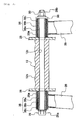
- Fig. 3 is a sectional view along line A-A in Fig. 1.
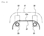
- Fig. 4 is a sectional view along line B-B in Fig. 1.
-
- 10
- Motorcycle
- 11
- Body frame
- 12
- Engine (Motor, Internal combustion engine)
- 12a
- Cylinder
- 12b
- Crankcase
- 15
- Head pipe
- 19
- Main frame
- 20
- Sub-frames
- 26
- Rear arms
- 28
- Brackets
- 29
- Pivot shaft
- An embodiment of the invention will be hereinafter explained on the basis of the drawings.
- As shown in Fig. 1, a saddle-riding type vehicle according to the embodiment is a
motorcycle 10 of a so-called underbone type. Themotorcycle 10 includes abody frame 11 forming a skeleton and anengine 12 supported by thebody frame 11 in a suspended state. - A
head pipe 15 is provided at a front end of thebody frame 11. A not-shown steering shaft is inserted into thehead pipe 15 to rotate freely. A not-shown front fork is provided on a lower side of the steering shaft. Afront wheel 18 is supported by thebody frame 11 to be capable of moving rotationally via the front fork and the like. - One
main frame 19 is fixed to thehead pipe 15. Themain frame 19 extends obliquely downward to the rear from thehead pipe 15. In order to secure sufficient strength, themain frame 19 is formed relatively thick and a section of themain frame 19 is formed in a hollow rectangular shape. In this embodiment, themain frame 19 is constituted by assembling a pair of left and right beam-shaped members. Specifically, themain frame 19 includes a pair of left and right beam-shaped members that extend obliquely downward to the rear and are bent 90 degrees at both top and bottom ends. Themain frame 19 is constituted by joining bent portions of the left and the right beam-shaped members in a left to right direction. However, it goes without saying that a method of forming the hollowmain frame 19 is not limited at all and other forming methods may be used. - A cross-sectional area of the
main frame 19 is different at afront end 19c and at arear end 19b connected to thehead pipe 15. The cross-sectional area of themain frame 19 is larger at thefront end 19c than therear end 19b and changes along a longitudinal direction of themain frame 19. Note that the cross-sectional area of themain frame 19 may change continuously along the longitudinal direction of themain frame 19 or may change stepwise. - A
gusset 27 is fixed to a lower side of a front half portion of themain frame 19. Thegusset 27 is arranged to be laid over between themain frame 19 and thehead pipe 15. - A
bracket 22 is fixed to a lower side of therear end 19b of themain frame 19. Acylinder 12a of theengine 12 is attached to thebracket 22 via a bolt and a nut. In other words, thecylinder 12a of theengine 12 is supported by themain frame 19 via thebracket 22. - The
engine 12 is a water-cooled engine. Theengine 12 includes thecylinder 12a and acrankcase 12b. Thecylinder 12a extends obliquely upward to the front from thecrankcase 12b. Thecylinder 12a includes a cylinder block and a cylinder head attached to an upper side of the cylinder block. Thecylinder 12a is supported in a posture with an axial direction of thecylinder 12a and a longitudinal direction of themain frame 19 substantially parallel to each other. - A
carburetor 13 is disposed behind thecylinder 12a. Thecarburetor 13 is arranged near a lower side of therear end 19b of themain frame 19, that is, on an extension line to the rear of themain frame 19. Anair cleaner 21 that purifies the outside air and supplies the outside air to thecarburetor 13 is disposed on a rear side of thecarburetor 13. Theair cleaner 21 is arranged in a position near thecarburetor 13, that is, a position adjacent to thecarburetor 13. Theair cleaner 21 assumes substantially a rectangular parallelepiped shape. As shown in Fig. 1, theair cleaner 21 is arranged obliquely such that an upper end side thereof is positioned further in the front of the vehicle than a lower end side thereof. - A
battery 34 is arranged behind and above theair cleaner 21. Thebattery 34 is located on a lower side of aseat 36 to be maintained by opening theseat 36. - In this way, since the
air cleaner 21 is arranged near the rear of thecarburetor 13, an air intake passage is made linear and simplified. Thus, it is possible to improve performance of theengine 12. Theair cleaner 21 and thebattery 34 are relatively large components. When theair cleaner 21 and thebattery 34 are arranged in a vehicle width direction, a vehicle width tends to be large. However, in themotorcycle 10, since theair cleaner 21 and thebattery 34 are arranged in a front to rear direction of the vehicle, it is possible to control the vehicle width and reduce width of the vehicle. Moreover, since theair cleaner 21 is arranged in a tilted posture, it is possible to effectively use a space on a lower side of thebattery 34 as a part of a space for setting theair cleaner 21. Therefore, it is possible to control length in the front to rear direction of the vehicle and height of the vehicle while securing a capacity of theair cleaner 21. - A
fuel tank 35 is disposed behind thebattery 34 and below theseat 36. - A
radiator 24 that cools cooling water supplied to theengine 12 is arranged above thecylinder 12a of theengine 12 and below themain frame 19. A not-shown bracket is provided in thegusset 27. Theradiator 24 is supported by thebody frame 11 via the bracket. - Incidentally, in the vehicle of the underbone type, that is, a vehicle in which the
main frame 19 inclines obliquely downward at a relatively steep angle, there is a problem described below concerning a space for setting theradiator 24. In the vehicle of the underbone type, when it is attempted to arrange theradiator 24 below themain frame 19 and above the cylinder head, a space for setting theradiator 24 is relatively limited. Thus, in themotorcycle 10, alower edge 27a of thegusset 27 is bent to be recessed upward. In other words, thelower edge 27a of thegusset 27 is bent to escape upward. Consequently, the space for setting theradiator 24 increases to prevent contact of thegusset 27 and theradiator 24. In other words, since thelower edge 27a of thegusset 27 is bent upward, thegusset 27 and theradiator 24 are less likely to interfere with each other. It is possible to efficiently arrange thegusset 27 in a limited space. Since this makes it possible to arrange thegusset 27 with a suitable size in a suitable position, it is possible to improve strength of themain frame 19. - As shown in Fig. 2,
sub-frames 20 are fixed to bothside portions 19a on the left and the right of themain frame 19. Specifically, a pair ofsub-frames 20 are provided on the left and the right andfront ends 20a of therespective sub-frames 20 are fixed near the center in the longitudinal direction of themain frame 19. Most parts of thesub-frames 20 assume a round pipe shape. A section of the sub-frames 20 is formed smaller than a section of themain frame 19. A shape of the front ends 20a of the sub-frames 20 is changed from the pipe shape to the planar shape toward a front side thereof. Portions of the planar shape are joined to theside portion 19a of themain frame 19 by welding or the like in a state in which the portions are in surface contact with theside portion 19a. - The sub-frames 20 have a bent structure. Specifically, as shown in Fig. 1, substantially the center in the longitudinal direction of the sub-frames 20 is bent to be projected downward.
Bent portions 20b are located above a boundary portion of thecrankcase 12b and thecylinder 12a of theengine 12.Front side portions 20c further on the front side than thebent portions 20b extend substantially parallel to an axial direction of thecylinder 12a of theengine 12.Rear side portions 20d further on a rear side than thebent portions 20b are inclined more gently than thefront side portions 20c. -
Brackets 23 are fixed torear side portions 20d (portions near the rear of thebent portions 20b) of the sub-frames 20. Thecrankcase 12b of theengine 12 is attached to thebrackets 23 via a bolt and a nut. - The
rear side portions 20d of thesub-frames 20 extend to the rear of theengine 12.Brackets 28 are fixed torear ends 20e of therear side portions 20d of the sub-frames 20. Both thecrankcase 12b of theengine 12 andrear arms 26 are supported by thebrackets 28. - Specifically, as shown in Fig. 1, the
brackets 28 made of metal extending downward, respectively, are fixed to therear ends 20e of the pair of left andright sub-frames 20. Apivot shaft 29 is suspended between thebrackets 28. As shown in Fig. 3, abolt head 29a is provided at one end of thepivot shaft 29 and amale thread portion 29b is formed at the other end. Themale thread portion 29b is screwed in anut 30. Thecrankcase 12b of theengine 12 and front endcylindrical portions 26a of therear arms 26 are supported by thepivot shaft 29 supported by thebrackets 28. - Specifically, as shown in Fig. 3, on the left side of the
engine 12, the front endcylindrical portion 26a of therear arm 26 on the left side is arranged between thebolt head 29a of thepivot shaft 29 and thebracket 28. The front endcylindrical portion 26a is supported by thepivot shaft 29 via abush 38 with internal and external cylinders and is capable of rotationally moving around thepivot shaft 29 within a predetermined angle range. Thebush 38 with internal and external cylinders includes aninner cylinder 38a and anouter cylinder 38c made of iron and anintermediate cylinder 38b made of rubber interposed between theinner cylinder 38a and theouter cylinder 38c. Thepivot shaft 29 is inserted into theinner cylinder 38a and theouter cylinder 38c is pressed into the front endcylindrical portion 26a of therear arm 26. Consequently, when the front endcylindrical portion 26a of therear arm 26 rotationally moves around thepivot shaft 29, theintermediate cylinder 38b made of rubber of thebush 38 with internal and external cylinders is elastically deformed to allow rotational movement of therear arm 26 and regulate rotational movement of therear arm 26 exceeding a predetermined range. - The front end
cylindrical portion 26a is also provided in therear arm 26 on the right side of theengine 12. The front endcylindrical portion 26a is arranged between thebracket 28 on the right side and awasher 33 on thenut 30 side. The front endcylindrical portion 26a of therear arm 26 on the right side is also supported to rotationally move freely by thepivot shaft 29 via thebush 38 with internal and external cylinders and rotationally moves in the predetermined angle range. - Moreover, the
crankcase 12b of theengine 12 is held between the pair of left andright brackets hole 12c extending to the left and the right is formed in thecrankcase 12b and thepivot shaft 29 is inserted through the through-hole 12c. With such a constitution, thecrankcase 12b is supported by thepivot shaft 29. - The
crankcase 12b of theengine 12, the left and theright brackets 28, and the left and the rightinner cylinders 38a are integrally combined by screwing themale thread portion 29b of thepivot shaft 29 in thenut 30. Theinner cylinder 38a on the right side is held between thebracket 28 on the right side and thenut 30 portion (accurately, the washer 33). Theinner cylinder 38a on the left side is held between thebracket 28 on the left side and thebolt head 29a. - As described above, the
engine 12 is attached to thebracket 22 fixed to themain frame 19 and thebrackets 23 and thebrackets 28 fixed to the left and the right sub-frames 20 (see Fig. 1). In this way, theengine 12 is suspended in a position of one place on themain frame 19 side and suspended in positions of two places separated to the front and the rear in the left and theright sub-frames 20. As a result, theengine 12 is supported in a state in which theengine 12 is laid over between both theframes frames frames engine 12. - One ends of seat rails 31 are connected to the
rear side portions 20d of the sub-frames 20. Specifically, front ends 31a of the seat rails 31 are welded in substantially the center in the longitudinal direction in therear side portions 20d of the sub-frames 20 (a position between both thebrackets 23 and 28). Front ends 32a of back stays 32 are welded to therear ends 20e of therear side portions 20d of thesub-frame 20. The seat rails 31 and the back stays 32 constitute a rear side frame extending obliquely upward to the rear and are formed in a round pipe shape, respectively. However, shapes of the seat rails 31 and the back stays 32 may be other shapes such as a square pipe shape. A material of the seat rails 31 and the back stays 32 may be iron, aluminum, and the like. Rear ends 32b of the back stays 32 are connected to intermediate portions of the seat rails 31. - As shown in Fig. 2, a
cross member 40 extending in the vehicle width direction is fixed to the pair of left and right seat rails 31. Thecross member 40 is laid over between the left and the right seat rails 31. Across member 41 extending in the vehicle width direction is also laid over between a pair of left and rightextended portion 26b in therear arms 26. Thecross member 41 is made of a pipe-like member that extends in substantially a U-shape. Both ends of the pipe-like member are joined to theextended portion 26b. - A
rear cushion 42 is disposed between thecross member 40 and thecross member 41. Anupper end 42a of therear cushion 42 is coupled to thecross member 40 on the seat rails 31 side to rotationally move freely. Alower end 42b of therear cushion 42 is coupled to thecross member 41 on therear arms 26 side to rotationally move freely. In themotorcycle 10, vibration from therear wheel 25 is absorbed by therear cushion 42. - As shown in Fig. 1, a
leg shield 37 covering upper sides of themain frame 19 and the left and theright sub-frames 20 is disposed in front of the seat 36 (see Fig. 4 as well). - The constitution of the
motorcycle 10 according to the embodiment is as described above. - In this way, in the
motorcycle 10, theengine 12 is fixed to be laid over between themain frame 19 and the sub-frames 20. Thus, theengine 12 also functions as a reinforcing member for thebody frame 11. Therefore, it is possible to realize a reduction in a size and a reduction in weight of thebody frame 11 while maintaining strength of the vehicle. - As shown in Fig. 4, according to the
motorcycle 10, it is possible to form thesub-frames 20 in a thin round pipe shape. Thus, it is possible to keep acenter tunnel portion 37a of theleg shield 37 in front of theseat 36 low. In other words, as indicated by an alternate long and two short dashes line in Fig. 4, when the sub-frames 20 are formed of relatively thick square pipes in order to increase strength, since positions of upper surfaces of the square pipes are elevated, a position of theleg shield 37 is also elevated as indicated by an alternate long and two short dashes line in the figure. On the other hand, in themotorcycle 10, since thesub-frames 20 are formed of a round pipe and thickness of the sub-frames 20 is reduced, it is possible to reduce height of theleg shield 37. - According to the
motorcycle 10, connecting positions of thesub-frames 20 and themain frame 19, that is, positions of the front ends 20a of thesub-frames 20 are ahead of a supporting portion of theengine 12 in themain frame 19, that is, a position of thebracket 22. In this way, since the front ends 20a of thesub-frames 20 are connected ahead of the supporting portion of the engine 12 (a portion where thebracket 22 is disposed) in themain frame 19, a portion between thefront end 19c of themain frame 19 and the supporting portion is reinforced by the sub-frames 20. Thus, it is possible to increase strength of themain frame 19. It is possible to effectively increase strength of themain frame 19 by contriving a connecting position of thesub-frames 20 according to a necessary strength distribution of themain frame 19. - The
main frame 19 is formed thicker at thefront end 19c than therear end 19b. Thus, on thefront end 19c side connected to thehead pipe 15, it is possible to secure strength against bending moment sufficiently. On the other hand, it is possible to form therear end 19b side thin. Since it is possible to form therear end 19b side thin in this way, it is possible to keep thecenter tunnel portion 37a of theleg shield 37 low. - The
cylinder 12a of theengine 12 is supported by themain frame 19 having large strength. Thus, it is possible to reduce length of themain frame 19 compared with a case in which thecylinder 12a of theengine 12 is supported by the sub-frames 20. Therefore, it is possible to realize a reduction in weight of thebody frame 11 while securing necessary strength. - The
cylinder 12a of theengine 12 is supported by, in particular, a portion near the rear end of themain frame 19, that is, therear end 19b. Thus, it is possible to reduce length of themain frame 19 and realize a further reduction in weight of thebody frame 11. - The
front side portions 20c of thesub-frames 20 extend substantially in parallel to the axial direction of thecylinder 12a of theengine 12. Thus, it is possible to effectively bring thefront side portions 20c of thesub-frames 20 close to thecylinder 12a. As a result, it is possible to reduce height of the sub-frames 20. Therefore, it is possible to keep thecenter tunnel portion 37a of theleg shield 37 low. - The
cylinder 12a of theengine 12 extends obliquely upward from thecrankcase 12b. Theengine 12 is formed in a shape bending upward as a whole. Thebent portions 20b of thesub-frames 20 are located above the boundary portion of thecylinder 12a of theengine 12 and thecrankcase 12. Thus, thesub-frames 20 are arranged along the bent shape of theengine 12. Therefore, since it is possible to arrange thesub-frames 20 in positions near theengine 12, it is possible to keep thecenter tunnel portion 37a of theleg shield 37 lower. - According to the
motorcycle 10, middle portions of thesub-frames 20 are bent to be recessed downward. Theengine 12 is supported near thebent portions 20b of the sub-frames 20. Thus, it is possible to reinforce strength in thebent portions 20b of thesub-frames 20 with theengine 12. Moreover, it is possible to keep thecenter tunnel portion 37a of theleg shield 37 lower. - According to the
motorcycle 10, the seat rails 31 extending obliquely upward to the rear is fixed to therear side portions 20d further on the rear side than thebent portions 20b of the sub-frames 20. Consequently, thesub-frames 20 are reinforced. Therefore, it is possible to reduce a diameter of thesub-frames 20 while securing strength of theentire body frame 11 and keep thecenter tunnel portion 37a of theleg shield 37 lower. - According to the
motorcycle 10, the portions further on the rear side than thebent portions 20b of thesub-frames 20 extend to the rear of theengine 12. Both theengine 12 and therear arms 26 are supported by the rear ends 20e of thesub-frames 20 via thebrackets 28. Consequently, it is possible to simplify a supporting structure for theengine 12 and the like and reduce a size of thebrackets 28. - The front ends 31a and 32a of the seat rails 31 and the back stays 32 extending obliquely upward to the rear are fixed to the
rear ends 20e of the sub-frames 20. The seat rails 31 and the back stays 32 are connected to each other on the rear end sides thereof. Consequently, it is possible to reduce a diameter of thesub-frames 20 while securing strength of thebody frame 11 and keep thecenter tunnel portion 37a of theleg shield 37 lower. - The
engine 12 is supported by portions near the connecting portions of the seat rails 31 and the back stays 32 in the sub-frames 20. Consequently, since theengine 12 is supported by portions having high strength in thesub-frames 20, it is possible to reduce thickness of thesub-frames 20 while securing strength of thebody frame 11. - The
engine 12 is supported by themain frame 19 via thebracket 22 and supported by portions of two places separated to the front and the rear of therespective sub-frames 20 via thebrackets 23 and thebrackets 28. Thus, theengine 12 is supported by themain frame 19 and thesub-frames 20 in a well-balanced state. The function of theengine 12 as a reinforcing member is improved to make it possible to obtain larger strength compared with a case in which theengine 12 is supported by one portion of the sub-frames 20. - The pair of
sub-frames 20 are provided on the left and the right, respectively. The pair ofbrackets 28 provided in the left and theright sub-frames 20 are interposed between therear arms 26 supporting therear wheel 25 and the engine 12 (see Fig. 3). Thus, it is possible to control an increase in an interval between the left and theright sub-frames 20 and reduce a width of the vehicle while maintaining strength of thebody frame 11. - Incidentally, when it is assumed that the
brackets 28 are disposed on an outer side of therear arms 26 and theinner cylinders 38a of thebush 38 with internal and external cylinders are directly in contact with thecrankcase 12b of theengine 12, it is likely that theinner cylinders 38a made of iron cut into thecrankcase 12b made of aluminum because of tightening of thenut 30 at the time of assembly. In that case, in order to prevent theinner cylinders 38a from cutting into thecrankcase 12b, it is necessary to dispose washers between theinner cylinders 38a and thecrankcase 12b. However, in themotorcycle 10, thetabular brackets 28 made of iron are interposed between theinner cylinders 38a made of iron and thecrankcase 12b made of aluminum. Thus, when thenut 30 is tightened, theinner cylinders 38a never cut into thecrankcase 12b side. Therefore, since it is unnecessary to provide washers, it is possible to reduce the number of components. - Note that, in the
motorcycle 10 according to the embodiment, the pair ofsub-frames 20 formed symmetrically are provided as the pair of left and right sub-frames. However, the pair of left and right sub-frames only have to be provided on the left and the right of the vehicle and do not always have to be formed symmetrically. - The
motorcycle 10 according to the embodiment includes theengine 12, which serves as an internal combustion engine, as the "motor". However, it goes without saying that the motor is not limited to theengine 12 and may be other motors such as an electric motor. The saddle-riding type vehicle according to the invention is not limited to themotorcycle 10. - As described above, the invention is useful for the saddle-riding type vehicle such as a motorcycle.
Claims (18)
- A saddle-riding type vehicle comprising:a head pipe that supports a steering shaft to rotationally move freely;a body frame including a main frame that is connected to the head pipe and extends obliquely downward to a rear and a pair of left and right sub-frames that are connected to the main frame and extend obliquely downward to the rear; anda motor supported by the main frame and the respective sub-frames in a suspended state.
- A saddle-riding type vehicle according to claim 1, wherein a connecting portion of the main frame and the sub-frames is located ahead of a portion supporting the motor in the main frame.
- A saddle-riding type vehicle according to claim 1 or 2, wherein
the head pipe is connected to a front end side of the main frame, and
a cross sectional area of the main frame changes along a longitudinal direction of the main frame such that the front end side is larger than a rear end side. - A saddle-riding type vehicle according to any one of claims 1 to 3, wherein the main frame supports the motor at the rear end of the main frame.
- A saddle-riding type vehicle according to any one of claims 1 to 4, wherein the sub-frames are bent convexly downward and support the motor at least in one place near bent portions.
- A saddle-riding type vehicle according to any one of claims 1 to 5, wherein the sub-frames are bent convexly downward and support the motor at least in one place further on a rear side than the bent portions.
- A saddle-riding type vehicle according to any one of claims 1 to 6, wherein
the saddle-riding type vehicle includes:a rear wheel; andrear arms that support the rear wheel and extend substantially in a front to rear direction,the sub-frame is bent convexly downward, andboth a part of the motor and the rear arms are supported at the rear ends of the sub-frames. - A saddle-riding type vehicle according to any one of claims 1 to 7, wherein
the sub-frames are bent convexly downward, and
the saddle-riding type vehicle includes rear side frames that are connected to a portion further on the rear side than the bent portions of the sub-frames and extend obliquely upward to the rear. - A saddle-riding type vehicle according to any one of claims 1 to 7, wherein
the saddle-riding type vehicle include plural rear side frames that are connected to the rear ends of the sub-frames, respectively, to extend obliquely upward to the rear and are connected to one another. - A saddle-riding type vehicle according to claim 8 or 9, wherein the sub-frames support the motor at least in one place near connecting portions to which the rear side frames are connected.
- A saddle-riding type vehicle according to any one of claims 1 to 10, wherein
the motor consists of an internal combustion engine having a crankcase and a cylinder that extends forward or obliquely upward to the front from the crankcase,
the cylinder is supported by the main frame, and
the crankcase is supported by the sub-frames. - A saddle-riding type vehicle according to claim 11, wherein
the cylinder extends obliquely upward to the front from the crankcase such that an axis of the cylinder extends obliquely in an upward direction,
the sub-frames are bent convexly downward, and
front side portions further on the front side than the bent portions in the sub-frames extend substantially parallel to the axis of the cylinder. - A saddle-riding type vehicle according to claim 11, wherein
the cylinder extends obliquely upward to the front from the crankcase such that the axis of the cylinder extends obliquely in the upward direction,
the sub-frames are bent convexly downward, and
the bent portions of the sub-frames are located above a boundary portion of the cylinder and the crankcase in the internal combustion engine. - A saddle-riding type vehicle comprising:a head pipe that supports a steering shaft to rotationally move freely;a body frame including a main frame that is connected to the head pipe and extends obliquely downward to the rear and a pair of left and right sub-frames that are connected to the main frame and extend obliquely downward to the rear; anda motor supported in positions of two places separated in a front to rear direction in the respective sub-frames in a suspended state.
- A saddle-riding type vehicle according to claim 14, wherein
the motor consists of an internal combustion engine including a crankcase and a cylinder that extends forward or obliquely upward to the front from the crankcase,
the cylinder is supported by the main frame, and
the crankcase is supported by the sub-frames. - A saddle-riding type vehicle comprising:a head pipe that supports a steering shaft to rotationally move freely;a body frame that extends obliquely downward to the rear from the head pipe; anda motor supported by the body frame in a suspended state,wherein the body frame includes at least a pair of left and right side frames, andthe saddle-riding type vehicle includes:a rear wheel;rear arms that support the rear wheel and extend substantially in a front to rear direction;left and right brackets fixed to the left and the right side frames, respectively; anda pivot shaft that pierces through both the brackets, both the rear arms, and the motor and attaches both the rear arms and the motor to both the brackets in a state in which the left and the right brackets are interposed between the left and the right rear arms and the motor, respectively.
- A saddle-riding type vehicle according to claim 16, wherein
the body frame includes a main frame that is connected to the head pipe and extends obliquely downward to the rear and a pair of left and right sub-frames that are connected to the main frame and extend obliquely downward to the rear, and
the side frames consist of the sub-frames. - A saddle-riding type vehicle according to claim 17, wherein a part of the motor is supported by the main frame.
Applications Claiming Priority (2)
| Application Number | Priority Date | Filing Date | Title |
|---|---|---|---|
| JP2003208098A JP2007022097A (en) | 2003-08-20 | 2003-08-20 | Saddle riding |
| PCT/JP2004/011092 WO2005019018A1 (en) | 2003-08-20 | 2004-08-03 | Saddle-riding type vehicle |
Publications (3)
| Publication Number | Publication Date |
|---|---|
| EP1657152A1 true EP1657152A1 (en) | 2006-05-17 |
| EP1657152A4 EP1657152A4 (en) | 2009-03-04 |
| EP1657152B1 EP1657152B1 (en) | 2010-10-06 |
Family
ID=34208961
Family Applications (1)
| Application Number | Title | Priority Date | Filing Date |
|---|---|---|---|
| EP04771146A Expired - Lifetime EP1657152B1 (en) | 2003-08-20 | 2004-08-03 | Saddle-riding type vehicle |
Country Status (9)
| Country | Link |
|---|---|
| US (1) | US8118127B2 (en) |
| EP (1) | EP1657152B1 (en) |
| JP (1) | JP2007022097A (en) |
| CN (1) | CN1839067B (en) |
| AT (1) | ATE483621T1 (en) |
| BR (1) | BRPI0413599B1 (en) |
| DE (1) | DE602004029475D1 (en) |
| ES (1) | ES2351984T3 (en) |
| WO (1) | WO2005019018A1 (en) |
Cited By (1)
| Publication number | Priority date | Publication date | Assignee | Title |
|---|---|---|---|---|
| CN103269947A (en) * | 2010-12-27 | 2013-08-28 | 本田技研工业株式会社 | Vehicle body frame for saddled vehicle |
Families Citing this family (6)
| Publication number | Priority date | Publication date | Assignee | Title |
|---|---|---|---|---|
| JP2010083380A (en) * | 2008-09-30 | 2010-04-15 | Honda Motor Co Ltd | Vehicle body frame structure of motorcycle |
| JP5898402B2 (en) * | 2010-12-24 | 2016-04-06 | 川崎重工業株式会社 | Motorcycle body frame |
| JP5694789B2 (en) * | 2011-01-17 | 2015-04-01 | 本田技研工業株式会社 | Fuel tank support structure for saddle-ride type vehicles |
| AU2012203514B2 (en) * | 2011-07-11 | 2014-07-17 | Honda Motor Co., Ltd. | Saddle type vehicle |
| JP6313622B2 (en) * | 2014-03-26 | 2018-04-18 | 本田技研工業株式会社 | Saddle riding vehicle |
| US11634191B2 (en) * | 2019-07-19 | 2023-04-25 | Curtiss Motorcycle Company, Inc. | Electric motorcycle with novel swing arm configuration |
Family Cites Families (32)
| Publication number | Priority date | Publication date | Assignee | Title |
|---|---|---|---|---|
| GB1356106A (en) * | 1970-07-07 | 1974-06-12 | Norton Villiers Ltd | Loop driven vehicles |
| US4139072A (en) * | 1974-11-21 | 1979-02-13 | Anthony Dawson | Motorcycle formed of detachable frame members |
| FR2369147A1 (en) * | 1976-11-01 | 1978-05-26 | Honda Motor Co Ltd | MOTORCYCLE FRAME |
| JPS6021113B2 (en) | 1978-11-11 | 1985-05-25 | ヤマハ発動機株式会社 | Chain-driven motorcycle with diamond frame |
| US4445585A (en) * | 1982-09-24 | 1984-05-01 | Yamaha Hatsudoki Kabushiki Kaisha | Motorcycle configuration |
| US4781264A (en) * | 1984-10-12 | 1988-11-01 | Honda Giken Kogyo Kabushiki Kaisha | Motor vehicle with riding saddle and horizontally disposed cushioning unit |
| JPH0741852B2 (en) * | 1985-05-09 | 1995-05-10 | 本田技研工業株式会社 | Rear-fender device for motorcycles |
| JP2598909B2 (en) * | 1987-06-16 | 1997-04-09 | ヤマハ発動機株式会社 | Body structure of motorcycle |
| EP0322305B1 (en) * | 1987-12-21 | 1994-04-06 | Honda Giken Kogyo Kabushiki Kaisha | Body frame for motor-bicycle |
| US5012883A (en) * | 1988-03-20 | 1991-05-07 | Honda Giken Kogyo Kabushiki Kaisha | Air duct device for a motorcycle |
| JP3034535B2 (en) * | 1989-07-25 | 2000-04-17 | 本田技研工業株式会社 | Muffler device for motorcycle |
| JP2951338B2 (en) | 1989-09-29 | 1999-09-20 | ヤマハ発動機株式会社 | Body frame structure of motorcycle |
| US5323869A (en) * | 1990-12-20 | 1994-06-28 | Honda Giken Kogyo Kabushiki Kaisha | Front fender mounting structure |
| JP3194204B2 (en) | 1992-05-28 | 2001-07-30 | ヤマハ発動機株式会社 | Pivot shaft tightening structure for motorcycles |
| JP3300956B2 (en) | 1992-05-28 | 2002-07-08 | ヤマハ発動機株式会社 | Rear wheel suspension for motorcycles |
| JPH0867285A (en) | 1994-08-31 | 1996-03-12 | Suzuki Motor Corp | A motorcycle to which an underbone type frame structure is applied, and an arrangement structure of an engine and an intake system on a frame of the motorcycle |
| JPH0995279A (en) * | 1995-09-29 | 1997-04-08 | Honda Motor Co Ltd | Motorcycle body frame |
| JP3539061B2 (en) * | 1996-04-30 | 2004-06-14 | スズキ株式会社 | Motorcycle frame structure |
| JP4043614B2 (en) * | 1998-09-11 | 2008-02-06 | 本田技研工業株式会社 | Pivot structure of rear swing arm |
| JP4067661B2 (en) * | 1998-09-11 | 2008-03-26 | 本田技研工業株式会社 | Body frame structure of motorcycle |
| JP4371180B2 (en) * | 1999-03-31 | 2009-11-25 | 本田技研工業株式会社 | Body frame structure of motorcycle |
| JP4132431B2 (en) * | 1999-06-29 | 2008-08-13 | 本田技研工業株式会社 | Motorcycle frame structure |
| JP4405001B2 (en) * | 1999-08-31 | 2010-01-27 | 本田技研工業株式会社 | Engine support structure for motorcycles |
| JP3122437B1 (en) * | 1999-09-21 | 2001-01-09 | 川崎重工業株式会社 | Vehicle engine intake system |
| JP2001247073A (en) * | 2000-03-02 | 2001-09-11 | Honda Motor Co Ltd | Body frame structure |
| JP2001280208A (en) * | 2000-03-31 | 2001-10-10 | Honda Motor Co Ltd | Motor cleaner air cleaner mounting structure |
| JP3766580B2 (en) * | 2000-03-31 | 2006-04-12 | 本田技研工業株式会社 | Manufacturing method of body frame for motorcycle |
| JP3476132B2 (en) * | 2000-03-31 | 2003-12-10 | 本田技研工業株式会社 | Motorcycle |
| JP3818570B2 (en) * | 2000-07-31 | 2006-09-06 | 本田技研工業株式会社 | Rear cushion mounting structure for motorcycles |
| DE60239223D1 (en) * | 2001-12-28 | 2011-03-31 | Yamaha Motor Co Ltd | VEHICLE CARRIER FRAME FOR MOTORCYCLE |
| JP4020264B2 (en) * | 2002-06-10 | 2007-12-12 | ヤマハ発動機株式会社 | Seat support structure for saddle riding type vehicles |
| JP3793129B2 (en) * | 2002-08-30 | 2006-07-05 | 川崎重工業株式会社 | Motorcycle body frame |
-
2003
- 2003-08-20 JP JP2003208098A patent/JP2007022097A/en active Pending
-
2004
- 2004-08-03 AT AT04771146T patent/ATE483621T1/en not_active IP Right Cessation
- 2004-08-03 BR BRPI0413599-7A patent/BRPI0413599B1/en not_active IP Right Cessation
- 2004-08-03 CN CN2004800238635A patent/CN1839067B/en not_active Expired - Lifetime
- 2004-08-03 ES ES04771146T patent/ES2351984T3/en not_active Expired - Lifetime
- 2004-08-03 DE DE602004029475T patent/DE602004029475D1/en not_active Expired - Lifetime
- 2004-08-03 EP EP04771146A patent/EP1657152B1/en not_active Expired - Lifetime
- 2004-08-03 WO PCT/JP2004/011092 patent/WO2005019018A1/en not_active Ceased
- 2004-08-03 US US10/568,487 patent/US8118127B2/en not_active Expired - Fee Related
Cited By (2)
| Publication number | Priority date | Publication date | Assignee | Title |
|---|---|---|---|---|
| CN103269947A (en) * | 2010-12-27 | 2013-08-28 | 本田技研工业株式会社 | Vehicle body frame for saddled vehicle |
| CN103269947B (en) * | 2010-12-27 | 2016-02-24 | 本田技研工业株式会社 | The vehicle body frame of Straddle-type vehicle |
Also Published As
| Publication number | Publication date |
|---|---|
| US8118127B2 (en) | 2012-02-21 |
| WO2005019018A1 (en) | 2005-03-03 |
| US20070056789A1 (en) | 2007-03-15 |
| CN1839067A (en) | 2006-09-27 |
| EP1657152B1 (en) | 2010-10-06 |
| BRPI0413599A (en) | 2006-10-17 |
| JP2007022097A (en) | 2007-02-01 |
| CN1839067B (en) | 2010-08-18 |
| ATE483621T1 (en) | 2010-10-15 |
| ES2351984T3 (en) | 2011-02-14 |
| DE602004029475D1 (en) | 2010-11-18 |
| EP1657152A4 (en) | 2009-03-04 |
| BRPI0413599B1 (en) | 2015-03-10 |
Similar Documents
| Publication | Publication Date | Title |
|---|---|---|
| JP5373181B2 (en) | Motorcycle | |
| US7699132B2 (en) | Motorcycle body frame structure | |
| EP3147191A1 (en) | Resonator structure of saddle-ride type vehicle | |
| JP2000085670A (en) | Body frame structure of motorcycle | |
| US10683053B2 (en) | Body frame structure of motorcycle | |
| JP6476224B2 (en) | Rear fender support structure for saddle-ride type vehicles | |
| US9751583B2 (en) | Engine supporting structure for saddle riding type vehicle | |
| JP2012254734A (en) | Frame structure of motor cycle | |
| EP1657152B1 (en) | Saddle-riding type vehicle | |
| JP2014043235A (en) | Fuel tank support structure of motor cycle | |
| JP2001063667A (en) | Engine support structure for motorcycles | |
| US7568548B2 (en) | Motorcycle | |
| JP5410340B2 (en) | Cushion support structure for saddle-ride type vehicles | |
| EP0447899B1 (en) | Frame construction for a motorcycle type vehicle | |
| JP5734417B2 (en) | Motorcycle frame | |
| EP3257733A1 (en) | Motorcycle | |
| JP5742505B2 (en) | Motorcycle frame, motorcycle | |
| EP2711277B1 (en) | Frame structure for saddle-riding type automotive vehicle | |
| US9815521B2 (en) | Exhaust system of saddle-ride type vehicle | |
| JP4153383B2 (en) | Body frame structure for motorcycles | |
| JP2010083328A (en) | Motorcycle | |
| JP7369750B2 (en) | saddle type vehicle | |
| JP2007196972A (en) | Motorcycle | |
| EP1759974B1 (en) | Motorcycle | |
| EP1447316B1 (en) | Power train for a motorcycle |
Legal Events
| Date | Code | Title | Description |
|---|---|---|---|
| PUAI | Public reference made under article 153(3) epc to a published international application that has entered the european phase |
Free format text: ORIGINAL CODE: 0009012 |
|
| 17P | Request for examination filed |
Effective date: 20060220 |
|
| AK | Designated contracting states |
Kind code of ref document: A1 Designated state(s): AT BE BG CH CY CZ DE DK EE ES FI FR GB GR HU IE IT LI LU MC NL PL PT RO SE SI SK TR |
|
| DAX | Request for extension of the european patent (deleted) | ||
| A4 | Supplementary search report drawn up and despatched |
Effective date: 20090129 |
|
| 17Q | First examination report despatched |
Effective date: 20090326 |
|
| GRAP | Despatch of communication of intention to grant a patent |
Free format text: ORIGINAL CODE: EPIDOSNIGR1 |
|
| RIC1 | Information provided on ipc code assigned before grant |
Ipc: B62K 11/04 20060101AFI20100305BHEP |
|
| RTI1 | Title (correction) |
Free format text: SADDLE-RIDING TYPE VEHICLE |
|
| GRAS | Grant fee paid |
Free format text: ORIGINAL CODE: EPIDOSNIGR3 |
|
| GRAA | (expected) grant |
Free format text: ORIGINAL CODE: 0009210 |
|
| AK | Designated contracting states |
Kind code of ref document: B1 Designated state(s): AT BE BG CH CY CZ DE DK EE ES FI FR GB GR HU IE IT LI LU MC NL PL PT RO SE SI SK TR |
|
| REG | Reference to a national code |
Ref country code: GB Ref legal event code: FG4D |
|
| REG | Reference to a national code |
Ref country code: CH Ref legal event code: EP |
|
| REG | Reference to a national code |
Ref country code: IE Ref legal event code: FG4D |
|
| REF | Corresponds to: |
Ref document number: 602004029475 Country of ref document: DE Date of ref document: 20101118 Kind code of ref document: P |
|
| REG | Reference to a national code |
Ref country code: GR Ref legal event code: EP Ref document number: 20100402699 Country of ref document: GR |
|
| REG | Reference to a national code |
Ref country code: NL Ref legal event code: VDEP Effective date: 20101006 |
|
| REG | Reference to a national code |
Ref country code: ES Ref legal event code: FG2A Effective date: 20110202 |
|
| PG25 | Lapsed in a contracting state [announced via postgrant information from national office to epo] |
Ref country code: SI Free format text: LAPSE BECAUSE OF FAILURE TO SUBMIT A TRANSLATION OF THE DESCRIPTION OR TO PAY THE FEE WITHIN THE PRESCRIBED TIME-LIMIT Effective date: 20101006 |
|
| PG25 | Lapsed in a contracting state [announced via postgrant information from national office to epo] |
Ref country code: AT Free format text: LAPSE BECAUSE OF FAILURE TO SUBMIT A TRANSLATION OF THE DESCRIPTION OR TO PAY THE FEE WITHIN THE PRESCRIBED TIME-LIMIT Effective date: 20101006 Ref country code: PT Free format text: LAPSE BECAUSE OF FAILURE TO SUBMIT A TRANSLATION OF THE DESCRIPTION OR TO PAY THE FEE WITHIN THE PRESCRIBED TIME-LIMIT Effective date: 20110207 Ref country code: SE Free format text: LAPSE BECAUSE OF FAILURE TO SUBMIT A TRANSLATION OF THE DESCRIPTION OR TO PAY THE FEE WITHIN THE PRESCRIBED TIME-LIMIT Effective date: 20101006 Ref country code: NL Free format text: LAPSE BECAUSE OF FAILURE TO SUBMIT A TRANSLATION OF THE DESCRIPTION OR TO PAY THE FEE WITHIN THE PRESCRIBED TIME-LIMIT Effective date: 20101006 Ref country code: BG Free format text: LAPSE BECAUSE OF FAILURE TO SUBMIT A TRANSLATION OF THE DESCRIPTION OR TO PAY THE FEE WITHIN THE PRESCRIBED TIME-LIMIT Effective date: 20110106 Ref country code: FI Free format text: LAPSE BECAUSE OF FAILURE TO SUBMIT A TRANSLATION OF THE DESCRIPTION OR TO PAY THE FEE WITHIN THE PRESCRIBED TIME-LIMIT Effective date: 20101006 |
|
| PG25 | Lapsed in a contracting state [announced via postgrant information from national office to epo] |
Ref country code: BE Free format text: LAPSE BECAUSE OF FAILURE TO SUBMIT A TRANSLATION OF THE DESCRIPTION OR TO PAY THE FEE WITHIN THE PRESCRIBED TIME-LIMIT Effective date: 20101006 |
|
| PG25 | Lapsed in a contracting state [announced via postgrant information from national office to epo] |
Ref country code: EE Free format text: LAPSE BECAUSE OF FAILURE TO SUBMIT A TRANSLATION OF THE DESCRIPTION OR TO PAY THE FEE WITHIN THE PRESCRIBED TIME-LIMIT Effective date: 20101006 Ref country code: CZ Free format text: LAPSE BECAUSE OF FAILURE TO SUBMIT A TRANSLATION OF THE DESCRIPTION OR TO PAY THE FEE WITHIN THE PRESCRIBED TIME-LIMIT Effective date: 20101006 |
|
| PLBE | No opposition filed within time limit |
Free format text: ORIGINAL CODE: 0009261 |
|
| STAA | Information on the status of an ep patent application or granted ep patent |
Free format text: STATUS: NO OPPOSITION FILED WITHIN TIME LIMIT |
|
| PG25 | Lapsed in a contracting state [announced via postgrant information from national office to epo] |
Ref country code: SK Free format text: LAPSE BECAUSE OF FAILURE TO SUBMIT A TRANSLATION OF THE DESCRIPTION OR TO PAY THE FEE WITHIN THE PRESCRIBED TIME-LIMIT Effective date: 20101006 Ref country code: PL Free format text: LAPSE BECAUSE OF FAILURE TO SUBMIT A TRANSLATION OF THE DESCRIPTION OR TO PAY THE FEE WITHIN THE PRESCRIBED TIME-LIMIT Effective date: 20101006 Ref country code: DK Free format text: LAPSE BECAUSE OF FAILURE TO SUBMIT A TRANSLATION OF THE DESCRIPTION OR TO PAY THE FEE WITHIN THE PRESCRIBED TIME-LIMIT Effective date: 20101006 Ref country code: RO Free format text: LAPSE BECAUSE OF FAILURE TO SUBMIT A TRANSLATION OF THE DESCRIPTION OR TO PAY THE FEE WITHIN THE PRESCRIBED TIME-LIMIT Effective date: 20101006 |
|
| 26N | No opposition filed |
Effective date: 20110707 |
|
| REG | Reference to a national code |
Ref country code: DE Ref legal event code: R097 Ref document number: 602004029475 Country of ref document: DE Effective date: 20110707 |
|
| PG25 | Lapsed in a contracting state [announced via postgrant information from national office to epo] |
Ref country code: MC Free format text: LAPSE BECAUSE OF NON-PAYMENT OF DUE FEES Effective date: 20110831 |
|
| REG | Reference to a national code |
Ref country code: CH Ref legal event code: PL |
|
| GBPC | Gb: european patent ceased through non-payment of renewal fee |
Effective date: 20110803 |
|
| PG25 | Lapsed in a contracting state [announced via postgrant information from national office to epo] |
Ref country code: CH Free format text: LAPSE BECAUSE OF NON-PAYMENT OF DUE FEES Effective date: 20110831 Ref country code: LI Free format text: LAPSE BECAUSE OF NON-PAYMENT OF DUE FEES Effective date: 20110831 |
|
| REG | Reference to a national code |
Ref country code: FR Ref legal event code: ST Effective date: 20120430 |
|
| REG | Reference to a national code |
Ref country code: IE Ref legal event code: MM4A |
|
| REG | Reference to a national code |
Ref country code: DE Ref legal event code: R119 Ref document number: 602004029475 Country of ref document: DE Effective date: 20120301 |
|
| PG25 | Lapsed in a contracting state [announced via postgrant information from national office to epo] |
Ref country code: IE Free format text: LAPSE BECAUSE OF NON-PAYMENT OF DUE FEES Effective date: 20110803 |
|
| PG25 | Lapsed in a contracting state [announced via postgrant information from national office to epo] |
Ref country code: GB Free format text: LAPSE BECAUSE OF NON-PAYMENT OF DUE FEES Effective date: 20110803 Ref country code: FR Free format text: LAPSE BECAUSE OF NON-PAYMENT OF DUE FEES Effective date: 20110831 |
|
| PG25 | Lapsed in a contracting state [announced via postgrant information from national office to epo] |
Ref country code: LU Free format text: LAPSE BECAUSE OF NON-PAYMENT OF DUE FEES Effective date: 20110803 Ref country code: CY Free format text: LAPSE BECAUSE OF EXPIRATION OF PROTECTION Effective date: 20101006 |
|
| PG25 | Lapsed in a contracting state [announced via postgrant information from national office to epo] |
Ref country code: DE Free format text: LAPSE BECAUSE OF NON-PAYMENT OF DUE FEES Effective date: 20120301 |
|
| PG25 | Lapsed in a contracting state [announced via postgrant information from national office to epo] |
Ref country code: HU Free format text: LAPSE BECAUSE OF FAILURE TO SUBMIT A TRANSLATION OF THE DESCRIPTION OR TO PAY THE FEE WITHIN THE PRESCRIBED TIME-LIMIT Effective date: 20101006 |
|
| P01 | Opt-out of the competence of the unified patent court (upc) registered |
Effective date: 20230527 |
|
| PGFP | Annual fee paid to national office [announced via postgrant information from national office to epo] |
Ref country code: TR Payment date: 20230801 Year of fee payment: 20 Ref country code: IT Payment date: 20230825 Year of fee payment: 20 |
|
| PGFP | Annual fee paid to national office [announced via postgrant information from national office to epo] |
Ref country code: GR Payment date: 20230822 Year of fee payment: 20 |
|
| PGFP | Annual fee paid to national office [announced via postgrant information from national office to epo] |
Ref country code: ES Payment date: 20231027 Year of fee payment: 20 |
|
| REG | Reference to a national code |
Ref country code: ES Ref legal event code: FD2A Effective date: 20240826 |
|
| PG25 | Lapsed in a contracting state [announced via postgrant information from national office to epo] |
Ref country code: ES Free format text: LAPSE BECAUSE OF EXPIRATION OF PROTECTION Effective date: 20240804 |
|
| PG25 | Lapsed in a contracting state [announced via postgrant information from national office to epo] |
Ref country code: ES Free format text: LAPSE BECAUSE OF EXPIRATION OF PROTECTION Effective date: 20240804 |