EP1657100A1 - Hybrid vehicle - Google Patents
Hybrid vehicle Download PDFInfo
- Publication number
- EP1657100A1 EP1657100A1 EP04771658A EP04771658A EP1657100A1 EP 1657100 A1 EP1657100 A1 EP 1657100A1 EP 04771658 A EP04771658 A EP 04771658A EP 04771658 A EP04771658 A EP 04771658A EP 1657100 A1 EP1657100 A1 EP 1657100A1
- Authority
- EP
- European Patent Office
- Prior art keywords
- motor
- generator
- transmission
- shaft
- engine
- Prior art date
- Legal status (The legal status is an assumption and is not a legal conclusion. Google has not performed a legal analysis and makes no representation as to the accuracy of the status listed.)
- Granted
Links
Images



Classifications
-
- B—PERFORMING OPERATIONS; TRANSPORTING
- B60—VEHICLES IN GENERAL
- B60K—ARRANGEMENT OR MOUNTING OF PROPULSION UNITS OR OF TRANSMISSIONS IN VEHICLES; ARRANGEMENT OR MOUNTING OF PLURAL DIVERSE PRIME-MOVERS IN VEHICLES; AUXILIARY DRIVES FOR VEHICLES; INSTRUMENTATION OR DASHBOARDS FOR VEHICLES; ARRANGEMENTS IN CONNECTION WITH COOLING, AIR INTAKE, GAS EXHAUST OR FUEL SUPPLY OF PROPULSION UNITS IN VEHICLES
- B60K6/00—Arrangement or mounting of plural diverse prime-movers for mutual or common propulsion, e.g. hybrid propulsion systems comprising electric motors and internal combustion engines
- B60K6/20—Arrangement or mounting of plural diverse prime-movers for mutual or common propulsion, e.g. hybrid propulsion systems comprising electric motors and internal combustion engines the prime-movers consisting of electric motors and internal combustion engines, e.g. HEVs
- B60K6/22—Arrangement or mounting of plural diverse prime-movers for mutual or common propulsion, e.g. hybrid propulsion systems comprising electric motors and internal combustion engines the prime-movers consisting of electric motors and internal combustion engines, e.g. HEVs characterised by apparatus, components or means specially adapted for HEVs
- B60K6/40—Arrangement or mounting of plural diverse prime-movers for mutual or common propulsion, e.g. hybrid propulsion systems comprising electric motors and internal combustion engines the prime-movers consisting of electric motors and internal combustion engines, e.g. HEVs characterised by apparatus, components or means specially adapted for HEVs characterised by the assembly or relative disposition of components
-
- B—PERFORMING OPERATIONS; TRANSPORTING
- B60—VEHICLES IN GENERAL
- B60K—ARRANGEMENT OR MOUNTING OF PROPULSION UNITS OR OF TRANSMISSIONS IN VEHICLES; ARRANGEMENT OR MOUNTING OF PLURAL DIVERSE PRIME-MOVERS IN VEHICLES; AUXILIARY DRIVES FOR VEHICLES; INSTRUMENTATION OR DASHBOARDS FOR VEHICLES; ARRANGEMENTS IN CONNECTION WITH COOLING, AIR INTAKE, GAS EXHAUST OR FUEL SUPPLY OF PROPULSION UNITS IN VEHICLES
- B60K6/00—Arrangement or mounting of plural diverse prime-movers for mutual or common propulsion, e.g. hybrid propulsion systems comprising electric motors and internal combustion engines
- B60K6/20—Arrangement or mounting of plural diverse prime-movers for mutual or common propulsion, e.g. hybrid propulsion systems comprising electric motors and internal combustion engines the prime-movers consisting of electric motors and internal combustion engines, e.g. HEVs
- B60K6/42—Arrangement or mounting of plural diverse prime-movers for mutual or common propulsion, e.g. hybrid propulsion systems comprising electric motors and internal combustion engines the prime-movers consisting of electric motors and internal combustion engines, e.g. HEVs characterised by the architecture of the hybrid electric vehicle
- B60K6/44—Series-parallel type
- B60K6/442—Series-parallel switching type
-
- B—PERFORMING OPERATIONS; TRANSPORTING
- B60—VEHICLES IN GENERAL
- B60K—ARRANGEMENT OR MOUNTING OF PROPULSION UNITS OR OF TRANSMISSIONS IN VEHICLES; ARRANGEMENT OR MOUNTING OF PLURAL DIVERSE PRIME-MOVERS IN VEHICLES; AUXILIARY DRIVES FOR VEHICLES; INSTRUMENTATION OR DASHBOARDS FOR VEHICLES; ARRANGEMENTS IN CONNECTION WITH COOLING, AIR INTAKE, GAS EXHAUST OR FUEL SUPPLY OF PROPULSION UNITS IN VEHICLES
- B60K6/00—Arrangement or mounting of plural diverse prime-movers for mutual or common propulsion, e.g. hybrid propulsion systems comprising electric motors and internal combustion engines
- B60K6/20—Arrangement or mounting of plural diverse prime-movers for mutual or common propulsion, e.g. hybrid propulsion systems comprising electric motors and internal combustion engines the prime-movers consisting of electric motors and internal combustion engines, e.g. HEVs
- B60K6/50—Architecture of the driveline characterised by arrangement or kind of transmission units
- B60K6/54—Transmission for changing ratio
- B60K6/543—Transmission for changing ratio the transmission being a continuously variable transmission
-
- Y—GENERAL TAGGING OF NEW TECHNOLOGICAL DEVELOPMENTS; GENERAL TAGGING OF CROSS-SECTIONAL TECHNOLOGIES SPANNING OVER SEVERAL SECTIONS OF THE IPC; TECHNICAL SUBJECTS COVERED BY FORMER USPC CROSS-REFERENCE ART COLLECTIONS [XRACs] AND DIGESTS
- Y02—TECHNOLOGIES OR APPLICATIONS FOR MITIGATION OR ADAPTATION AGAINST CLIMATE CHANGE
- Y02T—CLIMATE CHANGE MITIGATION TECHNOLOGIES RELATED TO TRANSPORTATION
- Y02T10/00—Road transport of goods or passengers
- Y02T10/60—Other road transportation technologies with climate change mitigation effect
- Y02T10/62—Hybrid vehicles
-
- Y—GENERAL TAGGING OF NEW TECHNOLOGICAL DEVELOPMENTS; GENERAL TAGGING OF CROSS-SECTIONAL TECHNOLOGIES SPANNING OVER SEVERAL SECTIONS OF THE IPC; TECHNICAL SUBJECTS COVERED BY FORMER USPC CROSS-REFERENCE ART COLLECTIONS [XRACs] AND DIGESTS
- Y02—TECHNOLOGIES OR APPLICATIONS FOR MITIGATION OR ADAPTATION AGAINST CLIMATE CHANGE
- Y02T—CLIMATE CHANGE MITIGATION TECHNOLOGIES RELATED TO TRANSPORTATION
- Y02T10/00—Road transport of goods or passengers
- Y02T10/80—Technologies aiming to reduce greenhouse gasses emissions common to all road transportation technologies
- Y02T10/92—Energy efficient charging or discharging systems for batteries, ultracapacitors, supercapacitors or double-layer capacitors specially adapted for vehicles
Definitions
- the present invention relates to a hybrid vehicle that can travel by means of either one or both of the driving force of an engine and the driving force of a generator/motor.
- the layout for an engine, a generator/motor, and a transmission that is conventionally employed is in general of a so-called sandwiched generator/motor type in which a thin generator/motor is sandwiched between the engine and the transmission.
- sandwiched generator/motor type since the generator/motor is joined to a crankshaft of the engine and an input shaft of the transmission and always rotates integrally therewith, when the generator/motor carries out regenerative braking during deceleration of the vehicle, there are the problems that friction in the engine and the transmission might degrade the energy recovery efficiency, and the friction of the engine is a load on the generator/motor when traveling by means of the generator/motor, thus increasing the power consumption.
- leg shaft drive system hybrid vehicle is known from, for example, Patent Publication 1 below in which the above-mentioned problems have been solved by enabling a generator/motor to be isolated from a crankshaft of an engine and an input shaft of a transmission, and enabling the driving force of the generator/motor to be transmitted to a driven wheel side rather than an output shaft of the transmission.
- the generator/motor is connected in series via a clutch to an end of the input shaft of the transmission on the side opposite to the engine, and by isolating the generator/motor from the input shaft of the transmission and the crankshaft of the engine by disengaging the clutch, the driving force of the generator/motor can be transmitted directly to the output shaft of the transmission.
- the present invention has been accomplished under the above-mentioned circumstances, and it is an object thereof to provide a hybrid vehicle that can employ the leg shaft drive system without subjecting a sandwiched generator/motor type transmission to large-scale design modification.
- a hybrid vehicle comprising: an engine having a crankshaft; a transmission that has an input shaft joined coaxially to the crankshaft and an output shaft disposed in parallel to the input shaft, and is capable of changing the gear ratio between the input shaft and the output shaft; and a generator/motor that is disposed at a position sandwiched between the engine and the transmission and a position off an axis of the input shaft, and transmits its driving force to any position of a power transmission pathway between the output shaft and a differential gear; the vehicle being capable of traveling by means of either one or both of the driving force of the engine and the driving force of the generator/motor.
- the generator/motor is disposed coaxially with the output shaft.
- a starter motor that can crank the crankshaft is disposed at a position sandwiched between the engine and the transmission, and at least parts of the generator/motor and the starter motor overlap each other when viewed in a direction perpendicular to the axis.
- the starter motor is disposed coaxially with the crankshaft.
- the driving force of the generator/motor is transmitted to any position of the power transmission pathway between the output shaft of the transmission and the differential gear, it is possible to carry out leg shaft drive in which transmission of the driving force between the generator/motor and the differential gear is carried out without going through the engine and the input shaft, power consumption can be reduced due to a decrease in friction, and the energy recovery efficiency during regenerative braking can be improved.
- the generator/motor since the generator/motor is disposed at a position sandwiched between the engine and the transmission, the generator/motor can be arranged in the same manner as for the conventional sandwiched generator/motor type, and not only can the leg shaft drive system be employed without greatly modifying the design of the sandwiched generator/motor type transmission, but also the axial dimension does not increase compared with the sandwiched generator/motor type transmission.
- the generator/motor is disposed coaxially with the output shaft, it is possible to easily avoid interference between the generator/motor and the output shaft.
- the starter motor is disposed at a position sandwiched between the engine and the transmission, it is possible to arrange the starter motor without greatly modifying the design of the sandwiched generator/motor type transmission.
- the starter motor since at least parts of the generator/motor and the starter motor overlap each other when viewed in a direction perpendicular to the axis of the input shaft, any increase in the axial dimension of the transmission can be suppressed effectively.
- the starter motor since the starter motor is disposed coaxially with the crankshaft, the engine can be started by means of a compact structure, and power can be generated by driving the starter motor by means of the engine.
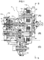
- FIG. 1 is a vertical sectional view of a power unit of a hybrid vehicle related to a first embodiment (Embodiment 1).
- FIG. 1 to FIG. 6 show a first embodiment of the present invention.
- a transmission case 11 of a transmission T mounted in a front part of a vehicle body of a front-engined/front wheel drive vehicle is divided into five, that is, a first casing 11 a, a second casing 11 b, a third casing 11 c, a fourth casing 11 d, and a fifth casing 11 e.
- a shaft end of a crankshaft 15 of an engine E faces an opening at the right-hand end of the first casing 11a, and an input shaft 16 (main shaft) of the transmission T, which shares an axis L with the crankshaft 15, is supported in the interior of the transmission case 11.
- an output shaft 17 (counter shaft) and a reduction shaft 18, which are parallel to the input shaft 16, and disposed beneath the reduction shaft 18 is a differential gear 19.
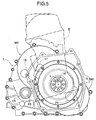
- the output shaft 17 is disposed above and behind the crankshaft 15 and the input shaft 16, which are disposed on the axis L, the reduction shaft 18 is disposed, behind the output shaft 17, and the differential gear 19 is disposed beneath the reduction shaft 18.
- a starter motor M2 disposed in a space surrounded by the first casing 11 a and the second casing 11 b is formed from a stator 23 fixed to the second casing 11 b via bolts 22, and a rotor 25 fixed to a starter motor shaft 24 supported via ball bearings 63 and 64 in front of and below the input shaft 16 (see FIG. 5), the stator 23 being provided with a plurality of coils 26, and the rotor 25 being provided with a plurality of permanent magnets 27.
- a drive sprocket 65 formed integrally with the starter motor shaft 24 and a driven sprocket 66 fixed to the input shaft 16 are connected via an endless chain 67; driving the starter motor M2 allows the crankshaft 15 to be cranked via the drive sprocket 65, the endless chain 67, the driven sprocket 66, and the input shaft 16, and on the other hand the driving force of the crankshaft 15 can drive the starter motor M2 so that it functions as a generator.
- a belt type continuously variable transmission 28 disposed in an internal space of the third casing 11 c includes a drive pulley 29 supported on the input shaft 16, a driven pulley 30 supported on the output shaft 17, and a metal belt 31 wound around the drive pulley 29 and the driven pulley 30.
- the drive pulley 29 is formed from a fixed pulley half 29a that can rotate relative to the input shaft 16 but cannot move axially relative thereto, and a movable pulley half 29b that can move toward and away from the fixed pulley half 29a, the movable pulley half 29b being capable of being urged toward the fixed pulley half 29a by means of hydraulic pressure supplied to a hydraulic chamber 32.
- the driven pulley 30 is formed from a fixed pulley half 30a that is integral with the output shaft 17 and a movable pulley half 30b that can move toward and away from the fixed pulley half 30a, the movable pulley half 30b being capable of being urged toward the fixed pulley half 30a by means of hydraulic pressure supplied to a hydraulic chamber 33.
- the gear ratio of the belt type continuously variable transmission 28 can therefore be changed to a LO side.
- the gear ratio of the belt type continuously variable transmission 28 can be changed to an OD side.
- a forward/reverse travel switching mechanism 41 is disposed between the left-hand end of the input shaft 16 and the drive pulley 29.
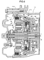
- the forward/reverse travel switching mechanism 41 is formed from a planetary gear mechanism 42, a forward clutch 43, and a reverse brake 44.
- Engaging the forward clutch 43 provides a direct connection between the input shaft 16 and the fixed pulley half 29a of the drive pulley 29, and engaging the reverse brake 44 allows the rotation of the input shaft 16 to be reduced in speed and transmitted, as reverse rotation, to the fixed pulley half 29a of the drive pulley 29.
- the planetary gear mechanism 42 includes a sun gear 45 joined to the input shaft 16, a planetary carrier 47 rotatably supported on the input shaft 16 via a ball bearing 46, a ring gear 48 relatively rotatably disposed on an outer peripheral part of the planetary carrier 47, and a plurality of pinions 50 rotatably supported on pinion shafts 49 fixed to the planetary carrier 47 and meshing with both the sun gear 45 and the ring gear 48.
- the forward clutch 43 includes a clutch outer 51 joined integrally to the fixed pulley half 29a of the drive pulley 29, a clutch inner 52 joined integrally to the sun gear 45, a plurality of frictional engagement members 53 that can provide a connection between the clutch outer 51 and the clutch inner 52, a clutch piston 55 driven by means of hydraulic pressure acting on a hydraulic chamber 54 so as to bring the frictional engagement members 53 into intimate contact with each other, and a return spring 56 urging the clutch piston 55 in a return direction. Therefore, engaging the forward clutch 43 allows the rotation of the input shaft 16 to be transmitted as it is to the drive pulley 29 via the sun gear 45, the clutch inner 52, the frictional engagement members 53, and the clutch outer 51, thus making the vehicle travel forward.
- the reverse brake 44 is formed from a plurality of frictional engagement members 57 that can provide a connection between the planetary carrier 47 and a fourth casing 11 d, a clutch piston 59 driven by means of hydraulic pressure acting on a hydraulic chamber 58 so as to bring the frictional engagement members 57 into intimate contact with each other, and return springs 60 urging the clutch piston 59 in a return direction. Therefore, engaging the reverse brake 44 allows the planetary carrier 47 of the planetary gear mechanism 42 to be restrained by the fourth casing 11 d so that it cannot rotate.
- a middle part of the input shaft 16 is supported on the third casing 11c via a ball bearing 61, and the fixed pulley half 29a of the drive pulley 29 is supported on the fourth casing 11 d via a ball bearing 62.
- numeral 68 in FIG. 2 is an oil pump, which is driven by the input shaft 16 via an endless chain 69.
- a middle part and a left-hand end part of the output shaft 17 are supported on the third casing 11c and the fourth casing 11 d via a roller bearing 71 and a ball bearing 73 respectively.
- a generator/motor M1 disposed coaxially with a right-hand portion of the output shaft 17 includes a hollow generator/motor shaft 75 supported on the outer periphery of the output shaft 17 via a pair of ball bearings 73 and 74, and a stator 77 surrounding the outside of a rotor 76 fixed to the outer periphery of the right-hand end of the generator/motor shaft 75 is fixed to the second casing 11b via bolts 78.
- a plurality of coils 79 are provided on the stator 77 of the generator/motor M1, and a plurality of permanent magnets 80 are provided on the rotor 76.
- a second reduction gear 83 and a final drive gear 84 are formed integrally with the reduction shaft 18, which is supported on the second casing 11 b and the third casing 11c via a pair of ball bearings 81 and 82, the second reduction gear 83 meshing with a first reduction gear 85 formed integrally with the generator/motor shaft 75, and the final drive gear 84 meshing with a final driven gear 86 of the differential gear 19.
- the differential gear 19 includes a differential case 89 supported on the second casing 11 b and the third casing 11 c via a pair of ball bearings 87 and 88, and the final driven gear 86 is fixed to the outer periphery of the differential case 89.
- a pair of differential pinions 91 are rotatably supported on a pinion shaft 90 fixed to the differential case 89, and a pair of differential side gears 94 fixed to opposing end parts of a left axle 92 and a right axle 93 running through the second casing 11 b, the third casing 11 c, and the differential case 89 each mesh with the pair of differential pinions 91.
- a starting clutch 95 that connects the generator/motor shaft 75 to the output shaft 17 includes a clutch inner 96 fixed to the generator/motor shaft 75, a clutch outer 97 fixed to the output shaft 17, frictional engagement members 98 supported on the clutch inner 96 and the clutch outer 97, a clutch piston 100 operated by means of hydraulic pressure supplied to a hydraulic chamber 99 so as to bring the frictional engagement members 98 into intimate contact with each other, and a return spring 101 returning the clutch piston 100 to an original position.
- Engaging the starting clutch 95 therefore allows the driving force of the output shaft 17 to be transmitted to the first reduction gear 85 of the generator/motor shaft 75, thus enabling travel by means of the driving force of the engine E.
- the driving force of the generator/motor M1 is transmitted via the pathway: generator/motor shaft 75 ⁇ first reduction gear 85 ⁇ second reduction gear 83 ⁇ reduction shaft 18 ⁇ final drive gear 84 ⁇ final driven gear 86 ⁇ differential gear 19 ⁇ left and right axles 92 and 93, thus allowing the vehicle to travel forward, and if the generator/motor M1 is driven in reverse, the vehicle can be made to travel in reverse.
- the leg shaft drive becomes possible merely by a slight modification of the sandwiched generator/motor type transmission. Furthermore, since the generator motor M1 and the starter motor M2 are both in a position off the axis L of the input shaft 16 and overlap each other when viewed in a direction perpendicular to the axis L, any increase in the dimension in the axis L direction of the transmission T can be suppressed effectively. Moreover, as is clear from FIG.
- FIG. 7 to FIG. 11 show a second embodiment of the present invention.
- components corresponding to the components of the first embodiment are denoted by the same reference numerals and symbols as those of the first embodiment, and duplication of the explanation is thus omitted. It is mainly the parts of the second embodiment that are different from those of the first embodiment that are explained below.
- the starter motor M2 is disposed in a position off the axis L of the input shaft 16
- a starter motor M2 is positioned on an axis L of an input shaft 16.
- the starter motor M2 is disposed between a crankshaft 15 and a damper 21, a stator 23 thereof is fixed to a first casing 11 a via bolts 22, and a rotor 25 thereof is fixed to the crankshaft 15. Therefore, an engine E can be started efficiently by directly cranking the crankshaft 15 by means of the rotor 25 of the starter motor M1, and the rotor 25 can be driven by means of the engine E, thus making the starter motor M2 function as a generator.
- the starter motor M2 is disposed coaxially with the crankshaft 15, it is possible to prevent the starter motor M2 from interfering with the crankshaft 15 or the input shaft 16.
- the generator/motor M1 is disposed coaxially with the output shaft 17
- a generator/motor M1 is disposed in a position away from an output shaft 17. That is, as is clear from FIG. 11, the output shaft 17 is disposed above and behind the crankshaft 15 and the input shaft 16, which are disposed on the axis L, a generator/motor shaft 111 is disposed above and behind the output shaft 17, a reduction shaft 18 is disposed beneath the generator/motor shaft 111, and a differential gear 19 is disposed beneath the reduction shaft 18.
- the generator/motor M1 which is housed in a space surrounded by a motor cover 112 and a second casing 11 b, the motor cover 112 being separate from a first casing 11 a, includes the generator/motor shaft 111, which is supported on the motor cover 112 and the second casing 11 b via ball bearings 113 and 114, and a stator 77 surrounding a rotor 76 fixed to the generator/motor shaft 111 is fixed to the second casing 11 b via bolts 78.
- a drive sprocket 115 provided integrally with the generator/motor shaft 111 and a driven sprocket 116 fixed to the reduction shaft 18 are connected via an endless chain 117, and power transmission between the generator/motor M1 and the reduction shaft 18 is carried out via the endless chain 117.
- the starting clutch 95 has a function of providing connections between the output shaft 17 and the first reduction gear 85 and generator/motor shaft 75
- a starting clutch 95 of the second embodiment only has a function of providing a connection between the output shaft 17 and a first reduction gear 85.
- the starting clutch 95 includes a clutch inner 119 that is integral with the first reduction gear 85, which is supported on the outer periphery of the output shaft 17 via a ball bearing 118, a clutch outer 120 that is integral with the output shaft 17, frictional engagement members 121 supported on the clutch inner 119 and the clutch outer 120, a clutch piston 123 operated by means of hydraulic pressure supplied to a hydraulic chamber 122 so as to bring the frictional engagement members 121 into intimate contact with each other, and a return spring 124 for returning the clutch piston 123 to an original position.
- Engaging the starting clutch 95 therefore allows the driving force of the output shaft 17 to be transmitted to the first reduction gear 85, thus enabling travel by means of the driving force of the engine E.
- the driving force of the generator/motor M1 is transmitted to the first reduction gear 85
- the driving force of the generator/motor M1 is transmitted to the reduction shaft 18
- the driving force of the starter motor M2 is transmitted to the input shaft 16 via the endless chain 67
- the driving force of the starter motor M2 is transmitted directly to the crankshaft 15, but other operations are the same.
- the driving force of the generator/motor M1 is transmitted to the reduction shaft 18 via the first and second reduction gears 85 and 83, but it may be transmitted via an endless chain or an endless belt
- the driving force of the generator/motor M1 is transmitted to the reduction shaft 18 via the endless chain 117, but it may be transmitted via a gear train or an endless belt.
- the transmission T of the embodiments is a continuously variable transmission having a belt type continuously variable transmission 28, but it may be any of a continuously variable transmission having any other structure, a stepped automatic transmission, or a manual transmission.
Landscapes
- Engineering & Computer Science (AREA)
- Chemical & Material Sciences (AREA)
- Combustion & Propulsion (AREA)
- Transportation (AREA)
- Mechanical Engineering (AREA)
- Hybrid Electric Vehicles (AREA)
- Arrangement Of Transmissions (AREA)
- Electric Propulsion And Braking For Vehicles (AREA)
- Control Of Vehicle Engines Or Engines For Specific Uses (AREA)
Abstract
Description
- The present invention relates to a hybrid vehicle that can travel by means of either one or both of the driving force of an engine and the driving force of a generator/motor.
- In such a hybrid vehicle, the layout for an engine, a generator/motor, and a transmission that is conventionally employed is in general of a so-called sandwiched generator/motor type in which a thin generator/motor is sandwiched between the engine and the transmission. In the layout of the sandwiched generator/motor type, since the generator/motor is joined to a crankshaft of the engine and an input shaft of the transmission and always rotates integrally therewith, when the generator/motor carries out regenerative braking during deceleration of the vehicle, there are the problems that friction in the engine and the transmission might degrade the energy recovery efficiency, and the friction of the engine is a load on the generator/motor when traveling by means of the generator/motor, thus increasing the power consumption.
- A so-called leg shaft drive system hybrid vehicle is known from, for example, Patent Publication 1 below in which the above-mentioned problems have been solved by enabling a generator/motor to be isolated from a crankshaft of an engine and an input shaft of a transmission, and enabling the driving force of the generator/motor to be transmitted to a driven wheel side rather than an output shaft of the transmission.
- In this hybrid vehicle, the generator/motor is connected in series via a clutch to an end of the input shaft of the transmission on the side opposite to the engine, and by isolating the generator/motor from the input shaft of the transmission and the crankshaft of the engine by disengaging the clutch, the driving force of the generator/motor can be transmitted directly to the output shaft of the transmission.
- Patent Publication 1: Japanese Patent Application Laid-open No. 2002-188716
- However, in the arrangement disclosed in Patent Publication 1 above, since the engine and the generator/motor are disposed at axially opposite ends of the input shaft of the transmission, a sandwiched generator/motor type transmission cannot be used as it is, and there is the problem that, in order to employ the leg shaft drive system, it is necessary to greatly modify the design of the transmission.
- The present invention has been accomplished under the above-mentioned circumstances, and it is an object thereof to provide a hybrid vehicle that can employ the leg shaft drive system without subjecting a sandwiched generator/motor type transmission to large-scale design modification.
- To accomplish the above object, according to a first aspect of the present invention, there is proposed a hybrid vehicle comprising: an engine having a crankshaft; a transmission that has an input shaft joined coaxially to the crankshaft and an output shaft disposed in parallel to the input shaft, and is capable of changing the gear ratio between the input shaft and the output shaft; and a generator/motor that is disposed at a position sandwiched between the engine and the transmission and a position off an axis of the input shaft, and transmits its driving force to any position of a power transmission pathway between the output shaft and a differential gear; the vehicle being capable of traveling by means of either one or both of the driving force of the engine and the driving force of the generator/motor.
- According to a second aspect of the present invention, in addition to the first aspect, the generator/motor is disposed coaxially with the output shaft.
- According to a third aspect of the present invention, in addition to either the first or second aspect, a starter motor that can crank the crankshaft is disposed at a position sandwiched between the engine and the transmission, and at least parts of the generator/motor and the starter motor overlap each other when viewed in a direction perpendicular to the axis.
- According to a fourth aspect of the present invention, in addition to the third aspect, the starter motor is disposed coaxially with the crankshaft.
- In accordance with the first aspect, since the driving force of the generator/motor is transmitted to any position of the power transmission pathway between the output shaft of the transmission and the differential gear, it is possible to carry out leg shaft drive in which transmission of the driving force between the generator/motor and the differential gear is carried out without going through the engine and the input shaft, power consumption can be reduced due to a decrease in friction, and the energy recovery efficiency during regenerative braking can be improved. Furthermore, since the generator/motor is disposed at a position sandwiched between the engine and the transmission, the generator/motor can be arranged in the same manner as for the conventional sandwiched generator/motor type, and not only can the leg shaft drive system be employed without greatly modifying the design of the sandwiched generator/motor type transmission, but also the axial dimension does not increase compared with the sandwiched generator/motor type transmission.
- In accordance with the second aspect, since the generator/motor is disposed coaxially with the output shaft, it is possible to easily avoid interference between the generator/motor and the output shaft.
- In accordance with the third aspect, since the starter motor is disposed at a position sandwiched between the engine and the transmission, it is possible to arrange the starter motor without greatly modifying the design of the sandwiched generator/motor type transmission. In particular, since at least parts of the generator/motor and the starter motor overlap each other when viewed in a direction perpendicular to the axis of the input shaft, any increase in the axial dimension of the transmission can be suppressed effectively.
- In accordance with the fourth aspect, since the starter motor is disposed coaxially with the crankshaft, the engine can be started by means of a compact structure, and power can be generated by driving the starter motor by means of the engine.
- [FIG. 1] FIG. 1 is a vertical sectional view of a power unit of a hybrid vehicle related to a first embodiment (Embodiment 1).
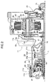
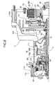
- [FIG. 2] FIG. 2 is an enlarged view of part A in FIG. 1 (Embodiment 1).
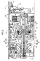
- [FIG. 3] FIG. 3 is an enlarged view of part B in FIG. 1 (Embodiment 1).
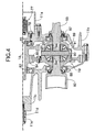
- [FIG. 4] FIG. 4 is an enlarged view of part C in FIG. 1 (Embodiment 1).
- [FIG. 5] FIG. 5 is a view from arrowed line 5-5 in FIG. 1 (Embodiment 1).
- [FIG. 6] FIG. 6 is an enlarged view of a forward/reverse travel switching mechanism (Embodiment 1).
- [FIG. 7] FIG. 7 is a vertical sectional view of a power unit of a hybrid vehicle related to a second embodiment (Embodiment 2).
- [FIG. 8] FIG. 8 is an enlarged view of part A in FIG. 7 (Embodiment 2).
- [FIG. 9] FIG. 9 is an enlarged view of part B in FIG. 7 (Embodiment 2).
- [FIG. 10] FIG. 10 is an enlarged view of part C in FIG. 7 (Embodiment 2).
- [FIG. 11] FIG. 11 is a view from arrowed line 11-11 in FIG. 7 (Embodiment 2).
-
- 15
- Crankshaft
- 16
- Input Shaft
- 17
- Output Shaft
- 19
- Differential Gear
- E
- Engine
- L
- Axis of Input Shaft
- M1
- Generator/Motor
- M2
- Starter Motor
- T
- Transmission
- Modes for carrying out the present invention are explained below by reference to embodiments of the present invention shown in the attached drawings.
- FIG. 1 to FIG. 6 show a first embodiment of the present invention.
- As shown in FIG. 1, a
transmission case 11 of a transmission T mounted in a front part of a vehicle body of a front-engined/front wheel drive vehicle is divided into five, that is, afirst casing 11 a, asecond casing 11 b, athird casing 11 c, afourth casing 11 d, and afifth casing 11 e. A shaft end of acrankshaft 15 of an engine E faces an opening at the right-hand end of thefirst casing 11a, and an input shaft 16 (main shaft) of the transmission T, which shares an axis L with thecrankshaft 15, is supported in the interior of thetransmission case 11. Furthermore, supported within thetransmission case 11 are an output shaft 17 (counter shaft) and areduction shaft 18, which are parallel to theinput shaft 16, and disposed beneath thereduction shaft 18 is adifferential gear 19. - As is clear from FIG. 5, the
output shaft 17 is disposed above and behind thecrankshaft 15 and theinput shaft 16, which are disposed on the axis L, thereduction shaft 18 is disposed, behind theoutput shaft 17, and thedifferential gear 19 is disposed beneath thereduction shaft 18. - As is clear from referring in addition to FIG. 2 to FIG. 4, the right-hand end of the
input shaft 16 and the left-hand end of thecrankshaft 15 are joined together via adamper 21 having the function of a flywheel. A starter motor M2 disposed in a space surrounded by thefirst casing 11 a and thesecond casing 11 b is formed from astator 23 fixed to thesecond casing 11 b viabolts 22, and arotor 25 fixed to astarter motor shaft 24 supported viaball bearings stator 23 being provided with a plurality ofcoils 26, and therotor 25 being provided with a plurality ofpermanent magnets 27. - A
drive sprocket 65 formed integrally with thestarter motor shaft 24 and a drivensprocket 66 fixed to theinput shaft 16 are connected via anendless chain 67; driving the starter motor M2 allows thecrankshaft 15 to be cranked via thedrive sprocket 65, theendless chain 67, the drivensprocket 66, and theinput shaft 16, and on the other hand the driving force of thecrankshaft 15 can drive the starter motor M2 so that it functions as a generator. - A belt type continuously
variable transmission 28 disposed in an internal space of thethird casing 11 c includes adrive pulley 29 supported on theinput shaft 16, a drivenpulley 30 supported on theoutput shaft 17, and ametal belt 31 wound around thedrive pulley 29 and the drivenpulley 30. Thedrive pulley 29 is formed from a fixedpulley half 29a that can rotate relative to theinput shaft 16 but cannot move axially relative thereto, and a movable pulley half 29b that can move toward and away from the fixedpulley half 29a, the movable pulley half 29b being capable of being urged toward the fixedpulley half 29a by means of hydraulic pressure supplied to ahydraulic chamber 32. Furthermore, the drivenpulley 30 is formed from a fixedpulley half 30a that is integral with theoutput shaft 17 and a movable pulley half 30b that can move toward and away from the fixedpulley half 30a, the movable pulley half 30b being capable of being urged toward the fixedpulley half 30a by means of hydraulic pressure supplied to ahydraulic chamber 33. - By controlling the hydraulic pressure supplied to the two
hydraulic chambers drive pulley 29 away from the fixedpulley half 29a and at the same time move the movable pulley half 30b of the drivenpulley 30 toward the fixedpulley half 30a, the gear ratio of the belt type continuouslyvariable transmission 28 can therefore be changed to a LO side. Furthermore, by controlling the hydraulic pressure supplied to the twohydraulic chambers drive pulley 29 toward the fixedpulley half 29a and at the same time move the movable pulley half 30b of the drivenpulley 30 away from the fixedpulley half 30a, the gear ratio of the belt type continuouslyvariable transmission 28 can be changed to an OD side. - A forward/reverse
travel switching mechanism 41 is disposed between the left-hand end of theinput shaft 16 and thedrive pulley 29. As is clear from FIG. 6, the forward/reversetravel switching mechanism 41 is formed from aplanetary gear mechanism 42, aforward clutch 43, and areverse brake 44. Engaging theforward clutch 43 provides a direct connection between theinput shaft 16 and the fixedpulley half 29a of thedrive pulley 29, and engaging thereverse brake 44 allows the rotation of theinput shaft 16 to be reduced in speed and transmitted, as reverse rotation, to the fixedpulley half 29a of thedrive pulley 29. - The
planetary gear mechanism 42 includes asun gear 45 joined to theinput shaft 16, aplanetary carrier 47 rotatably supported on theinput shaft 16 via aball bearing 46, aring gear 48 relatively rotatably disposed on an outer peripheral part of theplanetary carrier 47, and a plurality ofpinions 50 rotatably supported onpinion shafts 49 fixed to theplanetary carrier 47 and meshing with both thesun gear 45 and thering gear 48. - The
forward clutch 43 includes a clutch outer 51 joined integrally to the fixedpulley half 29a of thedrive pulley 29, a clutch inner 52 joined integrally to thesun gear 45, a plurality offrictional engagement members 53 that can provide a connection between the clutch outer 51 and the clutch inner 52, aclutch piston 55 driven by means of hydraulic pressure acting on ahydraulic chamber 54 so as to bring thefrictional engagement members 53 into intimate contact with each other, and a return spring 56 urging theclutch piston 55 in a return direction. Therefore, engaging theforward clutch 43 allows the rotation of theinput shaft 16 to be transmitted as it is to the drivepulley 29 via thesun gear 45, the clutch inner 52, thefrictional engagement members 53, and the clutch outer 51, thus making the vehicle travel forward. - The
reverse brake 44 is formed from a plurality offrictional engagement members 57 that can provide a connection between theplanetary carrier 47 and afourth casing 11 d, aclutch piston 59 driven by means of hydraulic pressure acting on ahydraulic chamber 58 so as to bring thefrictional engagement members 57 into intimate contact with each other, and returnsprings 60 urging theclutch piston 59 in a return direction. Therefore, engaging thereverse brake 44 allows theplanetary carrier 47 of theplanetary gear mechanism 42 to be restrained by thefourth casing 11 d so that it cannot rotate. In this process, since the extremity of the clutch outer 51 of theforward clutch 43 is engaged with thering gear 48 of theplanetary gear mechanism 42 so that they can rotate as a unit, the rotation of theinput shaft 16 is reduced in speed and transmitted, as reverse rotation, to the drivepulley 29 via thesun gear 45, thepinions 50, thering gear 48, and the clutch outer 54, thus making the vehicle travel in reverse. - A middle part of the
input shaft 16 is supported on thethird casing 11c via aball bearing 61, and the fixedpulley half 29a of thedrive pulley 29 is supported on thefourth casing 11 d via aball bearing 62. Furthermore, numeral 68 in FIG. 2 is an oil pump, which is driven by theinput shaft 16 via anendless chain 69. - A middle part and a left-hand end part of the
output shaft 17 are supported on thethird casing 11c and thefourth casing 11 d via a roller bearing 71 and aball bearing 73 respectively. A generator/motor M1 disposed coaxially with a right-hand portion of theoutput shaft 17 includes a hollow generator/motor shaft 75 supported on the outer periphery of theoutput shaft 17 via a pair ofball bearings stator 77 surrounding the outside of arotor 76 fixed to the outer periphery of the right-hand end of the generator/motor shaft 75 is fixed to thesecond casing 11b viabolts 78. A plurality ofcoils 79 are provided on thestator 77 of the generator/motor M1, and a plurality ofpermanent magnets 80 are provided on therotor 76. - A
second reduction gear 83 and afinal drive gear 84 are formed integrally with thereduction shaft 18, which is supported on thesecond casing 11 b and thethird casing 11c via a pair ofball bearings second reduction gear 83 meshing with afirst reduction gear 85 formed integrally with the generator/motor shaft 75, and thefinal drive gear 84 meshing with a final drivengear 86 of thedifferential gear 19. - The
differential gear 19 includes adifferential case 89 supported on thesecond casing 11 b and thethird casing 11 c via a pair ofball bearings gear 86 is fixed to the outer periphery of thedifferential case 89. A pair ofdifferential pinions 91 are rotatably supported on apinion shaft 90 fixed to thedifferential case 89, and a pair of differential side gears 94 fixed to opposing end parts of aleft axle 92 and aright axle 93 running through thesecond casing 11 b, thethird casing 11 c, and thedifferential case 89 each mesh with the pair of differential pinions 91. - A starting
clutch 95 that connects the generator/motor shaft 75 to theoutput shaft 17 includes a clutch inner 96 fixed to the generator/motor shaft 75, a clutch outer 97 fixed to theoutput shaft 17, frictional engagement members 98 supported on the clutch inner 96 and the clutch outer 97, aclutch piston 100 operated by means of hydraulic pressure supplied to ahydraulic chamber 99 so as to bring the frictional engagement members 98 into intimate contact with each other, and a return spring 101 returning theclutch piston 100 to an original position. Engaging the startingclutch 95 therefore allows the driving force of theoutput shaft 17 to be transmitted to thefirst reduction gear 85 of the generator/motor shaft 75, thus enabling travel by means of the driving force of the engine E. - The operation of the first embodiment having the above-mentioned arrangement is now explained.
- When the vehicle travels by means of the engine E, the driving force of the
crankshaft 15 of the engine E is transmitted via the pathway:damper 21 →input shaft 16 → forward/reversetravel switching mechanism 41 → belt type continuouslyvariable transmission 28 →output shaft 17 → starting clutch 95 →first reduction gear 85 →second reduction gear 83 →reduction shaft 18 →final drive gear 84 → final drivengear 86 →differential gear 19 → left andright axles forward clutch 43 of the forward/reversetravel switching mechanism 41 is engaged, the vehicle travels forward, if thereverse brake 44 is engaged, the vehicle travels in reverse, and by controlling the belt type continuouslyvariable transmission 28 any gear ratio can be obtained. - When traveling by means of the engine E, rotation of the
output shaft 17 is transmitted to the generator/motor shaft 75 via the startingclutch 95, thus allowing therotor 76 of the generator/motor M1 to rotate idle. In this process, if the generator/motor M1 is driven forward, the driving force of therotor 76 can assist forward travel by means of the engine E. If the generator/motor M1 is driven in reverse, the driving force of therotor 76 can assist reverse travel by means of the engine E. - If the generator/motor M1 is driven forward in a state in which the starting
clutch 95 is disengaged, the driving force of the generator/motor M1 is transmitted via the pathway: generator/motor shaft 75 →first reduction gear 85 →second reduction gear 83 →reduction shaft 18 →final drive gear 84 → final drivengear 86 →differential gear 19 → left andright axles - When traveling by means of the generator/motor M1 as described above, since the driving force of the generator/motor M1 does not drag along the engine E, the
input shaft 16, the forward/reversetravel switching mechanism 41, and theoutput shaft 17, the so-called leg shaft drive becomes possible, and the load on the generator/motor M1 is reduced, thus contributing to a saving in power consumption. Furthermore, when the generator/motor M1 carries out regenerative braking accompanying deceleration of the vehicle, since the driving force transmitted back from a wheel to the generator/motor M1 does not drag along the engine E, theinput shaft 16, the forward/reversetravel switching mechanism 41, and theoutput shaft 17, the energy recovery efficiency can be enhanced. - As hereinbefore described, since the generator/motor M1 and the starter motor M2 are disposed at positions sandwiched between the engine E and the transmission T, that is, the same positions as for the conventional sandwiched generator/motor type generator/motor, the leg shaft drive becomes possible merely by a slight modification of the sandwiched generator/motor type transmission. Furthermore, since the generator motor M1 and the starter motor M2 are both in a position off the axis L of the
input shaft 16 and overlap each other when viewed in a direction perpendicular to the axis L, any increase in the dimension in the axis L direction of the transmission T can be suppressed effectively. Moreover, as is clear from FIG. 5, since the generator/motor M1 and the starter motor M2 hardly protrude from the outline of the engine E and the transmission T in the axis L direction, any increase in the dimensions in the radial direction can also be suppressed. Furthermore, since the generator/motor M1 and the starter motor M2 are sandwiched between the engine E and the transmission T, which have a large heat capacity, ease of cooling thereof can readily be guaranteed. - FIG. 7 to FIG. 11 show a second embodiment of the present invention. In the second embodiment, components corresponding to the components of the first embodiment are denoted by the same reference numerals and symbols as those of the first embodiment, and duplication of the explanation is thus omitted. It is mainly the parts of the second embodiment that are different from those of the first embodiment that are explained below.
- Firstly, whereas in the first embodiment the starter motor M2 is disposed in a position off the axis L of the
input shaft 16, in the second embodiment a starter motor M2 is positioned on an axis L of aninput shaft 16. The starter motor M2 is disposed between acrankshaft 15 and adamper 21, astator 23 thereof is fixed to afirst casing 11 a viabolts 22, and arotor 25 thereof is fixed to thecrankshaft 15. Therefore, an engine E can be started efficiently by directly cranking thecrankshaft 15 by means of therotor 25 of the starter motor M1, and therotor 25 can be driven by means of the engine E, thus making the starter motor M2 function as a generator. Moreover, since the starter motor M2 is disposed coaxially with thecrankshaft 15, it is possible to prevent the starter motor M2 from interfering with thecrankshaft 15 or theinput shaft 16. - Furthermore, although in the first embodiment the generator/motor M1 is disposed coaxially with the
output shaft 17, in the second embodiment a generator/motor M1 is disposed in a position away from anoutput shaft 17. That is, as is clear from FIG. 11, theoutput shaft 17 is disposed above and behind thecrankshaft 15 and theinput shaft 16, which are disposed on the axis L, a generator/motor shaft 111 is disposed above and behind theoutput shaft 17, areduction shaft 18 is disposed beneath the generator/motor shaft 111, and adifferential gear 19 is disposed beneath thereduction shaft 18. - The generator/motor M1, which is housed in a space surrounded by a
motor cover 112 and asecond casing 11 b, themotor cover 112 being separate from afirst casing 11 a, includes the generator/motor shaft 111, which is supported on themotor cover 112 and thesecond casing 11 b viaball bearings 113 and 114, and astator 77 surrounding arotor 76 fixed to the generator/motor shaft 111 is fixed to thesecond casing 11 b viabolts 78. Adrive sprocket 115 provided integrally with the generator/motor shaft 111 and a drivensprocket 116 fixed to thereduction shaft 18 are connected via anendless chain 117, and power transmission between the generator/motor M1 and thereduction shaft 18 is carried out via theendless chain 117. - Furthermore, although in the first embodiment the starting
clutch 95 has a function of providing connections between theoutput shaft 17 and thefirst reduction gear 85 and generator/motor shaft 75, a startingclutch 95 of the second embodiment only has a function of providing a connection between theoutput shaft 17 and afirst reduction gear 85. That is, the startingclutch 95 includes a clutch inner 119 that is integral with thefirst reduction gear 85, which is supported on the outer periphery of theoutput shaft 17 via aball bearing 118, a clutch outer 120 that is integral with theoutput shaft 17,frictional engagement members 121 supported on the clutch inner 119 and the clutch outer 120, aclutch piston 123 operated by means of hydraulic pressure supplied to ahydraulic chamber 122 so as to bring thefrictional engagement members 121 into intimate contact with each other, and areturn spring 124 for returning theclutch piston 123 to an original position. Engaging the startingclutch 95 therefore allows the driving force of theoutput shaft 17 to be transmitted to thefirst reduction gear 85, thus enabling travel by means of the driving force of the engine E. - Whereas in the first embodiment the driving force of the generator/motor M1 is transmitted to the
first reduction gear 85, in the second embodiment the driving force of the generator/motor M1 is transmitted to thereduction shaft 18, and whereas in the first embodiment the driving force of the starter motor M2 is transmitted to theinput shaft 16 via theendless chain 67, in the second embodiment the driving force of the starter motor M2 is transmitted directly to thecrankshaft 15, but other operations are the same. - In accordance with this second embodiment also, since the generator/motor M1 and the starter motor M2 are disposed so as to be sandwiched between the engine E and the transmission T, leg shaft drive becomes possible merely by a slight modification of the sandwiched generator/motor type transmission. Furthermore, since the generator/motor M1 and the starter motor M2 overlap each other when viewed in a direction perpendicular to the axis L of the
input shaft 16, not only is it possible to suppress effectively any increase in the dimension in the axis L direction of the transmission T, but, as is clear from FIG. 11, since the generator motor M1 and the starter motor M2 hardly protrude from the outline in the axis L direction of the engine E and the transmission T, any increase in the dimensions in the radial direction can also be suppressed and, moreover, since the generator/motor M1 and the starter motor M2 are sandwiched between the engine E and the transmission T, which have a large heat capacity, the cooling effect is improved. - Although embodiments of the present invention are explained above, the present invention can be modified in a variety of ways as long as the modifications do not depart from the spirit and scope thereof.
- For example, in the first embodiment the driving force of the generator/motor M1 is transmitted to the
reduction shaft 18 via the first and second reduction gears 85 and 83, but it may be transmitted via an endless chain or an endless belt, and in the second embodiment the driving force of the generator/motor M1 is transmitted to thereduction shaft 18 via theendless chain 117, but it may be transmitted via a gear train or an endless belt. - Furthermore, the transmission T of the embodiments is a continuously variable transmission having a belt type continuously
variable transmission 28, but it may be any of a continuously variable transmission having any other structure, a stepped automatic transmission, or a manual transmission.
Claims (4)
- A hybrid vehicle comprising:an engine (E) having a crankshaft (15);a transmission (T) that has an input shaft (16) joined coaxially to the crankshaft (15) and an output shaft (17) disposed in parallel to the input shaft (16), and is capable of changing the gear ratio between the input shaft (16) and the output shaft (17); anda generator/motor (M1) that is disposed at a position sandwiched between the engine (E) and the transmission (T) and a position off an axis (L) of the input shaft (16), and transmits its driving force to any position of a power transmission pathway between the output shaft (17) and a differential gear (19);the vehicle being capable of traveling by means of either one or both of the driving force of the engine (E) and the driving force of the generator/motor (M1).
- The hybrid vehicle according to Claim 1, wherein the generator/motor (M1) is disposed coaxially with the output shaft (17).
- The hybrid vehicle according to either Claim 1 or Claim 2, wherein a starter motor (M2) that can crank the crankshaft (15) is disposed at a position sandwiched between the engine (E) and the transmission (T), and at least parts of the generator/motor (M1) and the starter motor (M2) overlap each other when viewed in a direction perpendicular to the axis (L).
- The hybrid vehicle according to Claim 3, wherein the starter motor (M2) is disposed coaxially with the crankshaft (15).
Applications Claiming Priority (2)
| Application Number | Priority Date | Filing Date | Title |
|---|---|---|---|
| JP2003294661A JP3845400B2 (en) | 2003-08-18 | 2003-08-18 | Hybrid vehicle |
| PCT/JP2004/011691 WO2005028233A1 (en) | 2003-08-18 | 2004-08-13 | Hybrid vehicle |
Publications (3)
| Publication Number | Publication Date |
|---|---|
| EP1657100A1 true EP1657100A1 (en) | 2006-05-17 |
| EP1657100A4 EP1657100A4 (en) | 2012-01-25 |
| EP1657100B1 EP1657100B1 (en) | 2012-12-26 |
Family
ID=34371164
Family Applications (1)
| Application Number | Title | Priority Date | Filing Date |
|---|---|---|---|
| EP04771658A Expired - Lifetime EP1657100B1 (en) | 2003-08-18 | 2004-08-13 | Hybrid vehicle |
Country Status (7)
| Country | Link |
|---|---|
| US (1) | US7568539B2 (en) |
| EP (1) | EP1657100B1 (en) |
| JP (1) | JP3845400B2 (en) |
| CN (1) | CN1835857B (en) |
| CA (1) | CA2533186C (en) |
| TW (1) | TWI241254B (en) |
| WO (1) | WO2005028233A1 (en) |
Cited By (3)
| Publication number | Priority date | Publication date | Assignee | Title |
|---|---|---|---|---|
| WO2018028738A1 (en) * | 2016-08-10 | 2018-02-15 | Schaeffler Technologies AG & Co. KG | Cvt drive train |
| CN109922980A (en) * | 2016-11-22 | 2019-06-21 | 舍弗勒技术股份两合公司 | Transmission components and drives for hybrid vehicles |
| WO2020094178A1 (en) * | 2018-11-06 | 2020-05-14 | Schaeffler Technologies AG & Co. KG | Hybrid powertrain and assembly method for a hybrid powertrain |
Families Citing this family (18)
| Publication number | Priority date | Publication date | Assignee | Title |
|---|---|---|---|---|
| JP4900693B2 (en) * | 2006-11-27 | 2012-03-21 | アイシン・エィ・ダブリュ株式会社 | Hybrid drive unit |
| JP4369966B2 (en) * | 2007-07-18 | 2009-11-25 | アイシン・エィ・ダブリュ株式会社 | Hybrid vehicle drive device |
| CN102940407A (en) * | 2007-08-17 | 2013-02-27 | 滑动存储自由轨道有限公司 | Track assembly for mobile shelving |
| DE102009045972A1 (en) * | 2009-10-26 | 2011-04-28 | Zf Friedrichshafen Ag | Drive train of a vehicle |
| US8549838B2 (en) | 2010-10-19 | 2013-10-08 | Cummins Inc. | System, method, and apparatus for enhancing aftertreatment regeneration in a hybrid power system |
| US8742701B2 (en) | 2010-12-20 | 2014-06-03 | Cummins Inc. | System, method, and apparatus for integrated hybrid power system thermal management |
| US8833496B2 (en) | 2010-12-20 | 2014-09-16 | Cummins Inc. | System, method, and apparatus for battery pack thermal management |
| US9096207B2 (en) | 2010-12-31 | 2015-08-04 | Cummins Inc. | Hybrid vehicle powertrain cooling system |
| US9043060B2 (en) | 2010-12-31 | 2015-05-26 | Cummins Inc. | Methods, systems, and apparatuses for driveline load management |
| US8473177B2 (en) | 2010-12-31 | 2013-06-25 | Cummins, Inc. | Apparatuses, methods, and systems for thermal management of hybrid vehicle SCR aftertreatment |
| JP5817741B2 (en) * | 2011-02-16 | 2015-11-18 | トヨタ自動車株式会社 | Vehicle and vehicle control method |
| CN102350939A (en) * | 2011-07-19 | 2012-02-15 | 东风汽车公司 | Driving system of hybrid electric vehicle |
| TWI485087B (en) * | 2011-11-29 | 2015-05-21 | Univ Nat Formosa | Electric vehicle planetary gearbox |
| US8936120B2 (en) * | 2011-12-29 | 2015-01-20 | Kawasaki Jukogyo Kabushiki Kaisha | Utility vehicle having a front electric motor |
| US8646563B2 (en) * | 2012-03-21 | 2014-02-11 | Deere & Company | Work machine with compact generator and hydraulic drive assembly |
| JP6252738B2 (en) * | 2013-09-13 | 2017-12-27 | 三菱自動車工業株式会社 | Transaxle device |
| JP7294911B2 (en) * | 2019-06-21 | 2023-06-20 | ジヤトコ株式会社 | hybrid vehicle |
| CN110979306B (en) * | 2019-12-07 | 2021-08-24 | 宁波吉利罗佑发动机零部件有限公司 | Method, device and system for configuring working mode of hybrid electric vehicle |
Family Cites Families (17)
| Publication number | Priority date | Publication date | Assignee | Title |
|---|---|---|---|---|
| US4583423A (en) * | 1983-02-24 | 1986-04-22 | Ford Motor Company | Infinitely variable transmission for automotive vehicle driveline |
| EP0281693B1 (en) * | 1987-03-10 | 1991-10-09 | National Research Development Corporation | Improvements in or relating to components in or for self-powered vehicles |
| JPH08266012A (en) | 1995-03-27 | 1996-10-11 | Motor Jidosha Kk | Compound motor |
| US6155364A (en) * | 1996-02-21 | 2000-12-05 | Toyota Jidosha Kabushiki Kaisha | Hybrid drive system wherein planetary gear mechanism is disposed radially inwardly of stator coil of motor/generator |
| JPH11180173A (en) | 1997-12-19 | 1999-07-06 | Mitsubishi Motors Corp | Drive device for hybrid electric vehicles |
| JP3803205B2 (en) | 1998-12-28 | 2006-08-02 | 本田技研工業株式会社 | Hybrid car |
| JP2000278809A (en) | 1999-03-25 | 2000-10-06 | Daihatsu Motor Co Ltd | Driving mechanism for hybrid vehicle |
| JP3647399B2 (en) * | 2000-09-14 | 2005-05-11 | 株式会社日立製作所 | Vehicle power transmission system and automobile equipped with the same |
| JP3556893B2 (en) * | 2000-10-11 | 2004-08-25 | 本田技研工業株式会社 | Power transmission mechanism |
| DE10052231A1 (en) * | 2000-10-21 | 2002-05-02 | Daimler Chrysler Ag | vehicle |
| JP3633473B2 (en) | 2000-11-02 | 2005-03-30 | トヨタ自動車株式会社 | Control device for hybrid drive mechanism with continuously variable transmission mechanism |
| JP2002188716A (en) | 2000-12-22 | 2002-07-05 | Aisin Seiki Co Ltd | Power transmission device for hybrid vehicles |
| JP3638876B2 (en) | 2001-03-01 | 2005-04-13 | 株式会社日立製作所 | Vehicle drive device and vehicle |
| JP3893938B2 (en) | 2001-10-22 | 2007-03-14 | トヨタ自動車株式会社 | Hybrid vehicle drive structure with transmission |
| JP2003154861A (en) | 2001-11-14 | 2003-05-27 | Ind Technol Res Inst | Parallel two-power unit combined power system |
| JP3882598B2 (en) | 2001-11-30 | 2007-02-21 | アイシン・エィ・ダブリュ株式会社 | Automatic transmission control device, automatic transmission control method and program thereof |
| JP3951904B2 (en) | 2002-11-29 | 2007-08-01 | 株式会社エクォス・リサーチ | Hybrid vehicle drive system |
-
2003
- 2003-08-18 JP JP2003294661A patent/JP3845400B2/en not_active Expired - Fee Related
-
2004
- 2004-08-13 CN CN2004800236080A patent/CN1835857B/en not_active Expired - Fee Related
- 2004-08-13 CA CA002533186A patent/CA2533186C/en not_active Expired - Fee Related
- 2004-08-13 EP EP04771658A patent/EP1657100B1/en not_active Expired - Lifetime
- 2004-08-13 US US10/567,435 patent/US7568539B2/en not_active Expired - Fee Related
- 2004-08-13 WO PCT/JP2004/011691 patent/WO2005028233A1/en not_active Ceased
- 2004-08-17 TW TW093124708A patent/TWI241254B/en not_active IP Right Cessation
Non-Patent Citations (2)
| Title |
|---|
| No further relevant documents disclosed * |
| See also references of WO2005028233A1 * |
Cited By (7)
| Publication number | Priority date | Publication date | Assignee | Title |
|---|---|---|---|---|
| WO2018028738A1 (en) * | 2016-08-10 | 2018-02-15 | Schaeffler Technologies AG & Co. KG | Cvt drive train |
| CN109922980A (en) * | 2016-11-22 | 2019-06-21 | 舍弗勒技术股份两合公司 | Transmission components and drives for hybrid vehicles |
| US11192442B2 (en) | 2016-11-22 | 2021-12-07 | Schaeffler Technologies AG & Co. KG | Transmission arrangement and drive device for a hybrid vehicle |
| WO2020094178A1 (en) * | 2018-11-06 | 2020-05-14 | Schaeffler Technologies AG & Co. KG | Hybrid powertrain and assembly method for a hybrid powertrain |
| CN112672900A (en) * | 2018-11-06 | 2021-04-16 | 舍弗勒技术股份两合公司 | Hybrid powertrain and method of assembly for a hybrid powertrain |
| US11993151B2 (en) | 2018-11-06 | 2024-05-28 | Schaeffler Technologies AG & Co. KG | Hybrid powertrain and assembly method for a hybrid powertrain |
| CN112672900B (en) * | 2018-11-06 | 2024-07-23 | 舍弗勒技术股份两合公司 | Hybrid powertrain and assembly method for hybrid powertrain |
Also Published As
| Publication number | Publication date |
|---|---|
| EP1657100A4 (en) | 2012-01-25 |
| JP3845400B2 (en) | 2006-11-15 |
| EP1657100B1 (en) | 2012-12-26 |
| US20070084649A1 (en) | 2007-04-19 |
| JP2005059787A (en) | 2005-03-10 |
| CN1835857B (en) | 2010-05-12 |
| CA2533186C (en) | 2008-02-12 |
| WO2005028233A1 (en) | 2005-03-31 |
| US7568539B2 (en) | 2009-08-04 |
| CA2533186A1 (en) | 2005-03-31 |
| TW200512107A (en) | 2005-04-01 |
| TWI241254B (en) | 2005-10-11 |
| CN1835857A (en) | 2006-09-20 |
Similar Documents
| Publication | Publication Date | Title |
|---|---|---|
| EP1657100B1 (en) | Hybrid vehicle | |
| US7506710B2 (en) | Hybrid vehicle | |
| KR100389599B1 (en) | Hybrid driver | |
| US8469848B2 (en) | Vehicular drive apparatus | |
| JP5120432B2 (en) | Hybrid drive unit | |
| JP6812835B2 (en) | Transaxle device | |
| JP2021049980A (en) | Transaxle device | |
| JP2010006190A (en) | Hybrid vehicle power unit | |
| JP3144390B2 (en) | Hybrid drive | |
| JP2007022112A (en) | Motor device installing structure of hybrid vehicle | |
| JP3578151B2 (en) | Hydraulic supply device for hybrid vehicle | |
| JP2011226527A (en) | Transmission unit for electric vehicle | |
| JP5115465B2 (en) | Drive device | |
| JP3373082B2 (en) | Hybrid vehicle | |
| JP3396868B2 (en) | Hybrid vehicle | |
| JP5039647B2 (en) | Power transmission device | |
| JP5026950B2 (en) | Vehicle drive device | |
| JP4516655B2 (en) | Starting clutch | |
| JPH0478860B2 (en) | ||
| JP2007261347A (en) | Hybrid vehicle | |
| CN2514129Y (en) | Special engine with reverse gear and differential gear | |
| JP2020139509A (en) | Drive device for vehicle |
Legal Events
| Date | Code | Title | Description |
|---|---|---|---|
| PUAI | Public reference made under article 153(3) epc to a published international application that has entered the european phase |
Free format text: ORIGINAL CODE: 0009012 |
|
| 17P | Request for examination filed |
Effective date: 20060126 |
|
| AK | Designated contracting states |
Kind code of ref document: A1 Designated state(s): DE FR GB IT |
|
| DAX | Request for extension of the european patent (deleted) | ||
| RBV | Designated contracting states (corrected) |
Designated state(s): DE FR GB IT |
|
| A4 | Supplementary search report drawn up and despatched |
Effective date: 20111229 |
|
| RIC1 | Information provided on ipc code assigned before grant |
Ipc: B60L 11/14 20060101ALI20111229BHEP Ipc: B60K 17/04 20060101AFI20111229BHEP Ipc: B60K 6/40 20071001ALI20111229BHEP |
|
| REG | Reference to a national code |
Ref country code: DE Ref legal event code: R079 Ref document number: 602004040545 Country of ref document: DE Free format text: PREVIOUS MAIN CLASS: B60K0017040000 Ipc: B60K0006442000 |
|
| GRAP | Despatch of communication of intention to grant a patent |
Free format text: ORIGINAL CODE: EPIDOSNIGR1 |
|
| RIC1 | Information provided on ipc code assigned before grant |
Ipc: B60K 6/442 20071001AFI20120702BHEP Ipc: B60K 6/543 20071001ALI20120702BHEP Ipc: B60K 6/40 20071001ALI20120702BHEP |
|
| GRAS | Grant fee paid |
Free format text: ORIGINAL CODE: EPIDOSNIGR3 |
|
| GRAA | (expected) grant |
Free format text: ORIGINAL CODE: 0009210 |
|
| RIN1 | Information on inventor provided before grant (corrected) |
Inventor name: OKADA, YOSHIO, Inventor name: ABE, NORIYUKI, |
|
| AK | Designated contracting states |
Kind code of ref document: B1 Designated state(s): DE FR GB IT |
|
| RAP1 | Party data changed (applicant data changed or rights of an application transferred) |
Owner name: HONDA MOTOR CO., LTD. |
|
| REG | Reference to a national code |
Ref country code: GB Ref legal event code: FG4D |
|
| REG | Reference to a national code |
Ref country code: DE Ref legal event code: R096 Ref document number: 602004040545 Country of ref document: DE Effective date: 20130307 |
|
| PGFP | Annual fee paid to national office [announced via postgrant information from national office to epo] |
Ref country code: DE Payment date: 20130614 Year of fee payment: 10 |
|
| PLBE | No opposition filed within time limit |
Free format text: ORIGINAL CODE: 0009261 |
|
| STAA | Information on the status of an ep patent application or granted ep patent |
Free format text: STATUS: NO OPPOSITION FILED WITHIN TIME LIMIT |
|
| PGFP | Annual fee paid to national office [announced via postgrant information from national office to epo] |
Ref country code: GB Payment date: 20130730 Year of fee payment: 10 |
|
| 26N | No opposition filed |
Effective date: 20130927 |
|
| PG25 | Lapsed in a contracting state [announced via postgrant information from national office to epo] |
Ref country code: IT Free format text: LAPSE BECAUSE OF FAILURE TO SUBMIT A TRANSLATION OF THE DESCRIPTION OR TO PAY THE FEE WITHIN THE PRESCRIBED TIME-LIMIT Effective date: 20121226 |
|
| REG | Reference to a national code |
Ref country code: DE Ref legal event code: R097 Ref document number: 602004040545 Country of ref document: DE Effective date: 20130927 |
|
| REG | Reference to a national code |
Ref country code: FR Ref legal event code: ST Effective date: 20140430 |
|
| PG25 | Lapsed in a contracting state [announced via postgrant information from national office to epo] |
Ref country code: FR Free format text: LAPSE BECAUSE OF NON-PAYMENT OF DUE FEES Effective date: 20130902 |
|
| REG | Reference to a national code |
Ref country code: DE Ref legal event code: R119 Ref document number: 602004040545 Country of ref document: DE |
|
| GBPC | Gb: european patent ceased through non-payment of renewal fee |
Effective date: 20140813 |
|
| REG | Reference to a national code |
Ref country code: DE Ref legal event code: R119 Ref document number: 602004040545 Country of ref document: DE Effective date: 20150303 |
|
| PG25 | Lapsed in a contracting state [announced via postgrant information from national office to epo] |
Ref country code: GB Free format text: LAPSE BECAUSE OF NON-PAYMENT OF DUE FEES Effective date: 20140813 Ref country code: DE Free format text: LAPSE BECAUSE OF NON-PAYMENT OF DUE FEES Effective date: 20150303 |