EP1657090A2 - Klimaanlage mit Kältespeicher - Google Patents
Klimaanlage mit Kältespeicher Download PDFInfo
- Publication number
- EP1657090A2 EP1657090A2 EP05024814A EP05024814A EP1657090A2 EP 1657090 A2 EP1657090 A2 EP 1657090A2 EP 05024814 A EP05024814 A EP 05024814A EP 05024814 A EP05024814 A EP 05024814A EP 1657090 A2 EP1657090 A2 EP 1657090A2
- Authority
- EP
- European Patent Office
- Prior art keywords
- cold storage
- evaporator
- air conditioning
- conditioning system
- storage element
- Prior art date
- Legal status (The legal status is an assumption and is not a legal conclusion. Google has not performed a legal analysis and makes no representation as to the accuracy of the status listed.)
- Granted
Links
Images


Classifications
-
- F—MECHANICAL ENGINEERING; LIGHTING; HEATING; WEAPONS; BLASTING
- F28—HEAT EXCHANGE IN GENERAL
- F28D—HEAT-EXCHANGE APPARATUS, NOT PROVIDED FOR IN ANOTHER SUBCLASS, IN WHICH THE HEAT-EXCHANGE MEDIA DO NOT COME INTO DIRECT CONTACT
- F28D20/00—Heat storage plants or apparatus in general; Regenerative heat-exchange apparatus not covered by groups F28D17/00 or F28D19/00
- F28D20/02—Heat storage plants or apparatus in general; Regenerative heat-exchange apparatus not covered by groups F28D17/00 or F28D19/00 using latent heat
-
- B—PERFORMING OPERATIONS; TRANSPORTING
- B60—VEHICLES IN GENERAL
- B60H—ARRANGEMENTS OF HEATING, COOLING, VENTILATING OR OTHER AIR-TREATING DEVICES SPECIALLY ADAPTED FOR PASSENGER OR GOODS SPACES OF VEHICLES
- B60H1/00—Heating, cooling or ventilating devices
- B60H1/00492—Heating, cooling or ventilating devices comprising regenerative heating or cooling means, e.g. heat accumulators
- B60H1/005—Regenerative cooling means, e.g. cold accumulators
-
- F—MECHANICAL ENGINEERING; LIGHTING; HEATING; WEAPONS; BLASTING
- F28—HEAT EXCHANGE IN GENERAL
- F28D—HEAT-EXCHANGE APPARATUS, NOT PROVIDED FOR IN ANOTHER SUBCLASS, IN WHICH THE HEAT-EXCHANGE MEDIA DO NOT COME INTO DIRECT CONTACT
- F28D1/00—Heat-exchange apparatus having stationary conduit assemblies for one heat-exchange medium only, the media being in contact with different sides of the conduit wall, in which the other heat-exchange medium is a large body of fluid, e.g. domestic or motor car radiators
- F28D1/02—Heat-exchange apparatus having stationary conduit assemblies for one heat-exchange medium only, the media being in contact with different sides of the conduit wall, in which the other heat-exchange medium is a large body of fluid, e.g. domestic or motor car radiators with heat-exchange conduits immersed in the body of fluid
- F28D1/04—Heat-exchange apparatus having stationary conduit assemblies for one heat-exchange medium only, the media being in contact with different sides of the conduit wall, in which the other heat-exchange medium is a large body of fluid, e.g. domestic or motor car radiators with heat-exchange conduits immersed in the body of fluid with tubular conduits
- F28D1/053—Heat-exchange apparatus having stationary conduit assemblies for one heat-exchange medium only, the media being in contact with different sides of the conduit wall, in which the other heat-exchange medium is a large body of fluid, e.g. domestic or motor car radiators with heat-exchange conduits immersed in the body of fluid with tubular conduits the conduits being straight
- F28D1/0535—Heat-exchange apparatus having stationary conduit assemblies for one heat-exchange medium only, the media being in contact with different sides of the conduit wall, in which the other heat-exchange medium is a large body of fluid, e.g. domestic or motor car radiators with heat-exchange conduits immersed in the body of fluid with tubular conduits the conduits being straight the conduits having a non-circular cross-section
- F28D1/05366—Assemblies of conduits connected to common headers, e.g. core type radiators
- F28D1/05391—Assemblies of conduits connected to common headers, e.g. core type radiators with multiple rows of conduits or with multi-channel conduits combined with a particular flow pattern, e.g. multi-row multi-stage radiators
-
- F—MECHANICAL ENGINEERING; LIGHTING; HEATING; WEAPONS; BLASTING
- F28—HEAT EXCHANGE IN GENERAL
- F28D—HEAT-EXCHANGE APPARATUS, NOT PROVIDED FOR IN ANOTHER SUBCLASS, IN WHICH THE HEAT-EXCHANGE MEDIA DO NOT COME INTO DIRECT CONTACT
- F28D21/00—Heat-exchange apparatus not covered by any of the groups F28D1/00 - F28D20/00
- F28D2021/0019—Other heat exchangers for particular applications; Heat exchange systems not otherwise provided for
- F28D2021/008—Other heat exchangers for particular applications; Heat exchange systems not otherwise provided for for vehicles
- F28D2021/0085—Evaporators
-
- Y—GENERAL TAGGING OF NEW TECHNOLOGICAL DEVELOPMENTS; GENERAL TAGGING OF CROSS-SECTIONAL TECHNOLOGIES SPANNING OVER SEVERAL SECTIONS OF THE IPC; TECHNICAL SUBJECTS COVERED BY FORMER USPC CROSS-REFERENCE ART COLLECTIONS [XRACs] AND DIGESTS
- Y02—TECHNOLOGIES OR APPLICATIONS FOR MITIGATION OR ADAPTATION AGAINST CLIMATE CHANGE
- Y02E—REDUCTION OF GREENHOUSE GAS [GHG] EMISSIONS, RELATED TO ENERGY GENERATION, TRANSMISSION OR DISTRIBUTION
- Y02E60/00—Enabling technologies; Technologies with a potential or indirect contribution to GHG emissions mitigation
- Y02E60/14—Thermal energy storage
Definitions
- the invention relates to an air conditioner with cold storage for a motor vehicle according to the preamble of claim 1.
- One measure to reduce fuel consumption is to shut down the engine during a temporary standstill, such as when stopping at a traffic light. This temporary shutdown of the engine is also called idle-stop operation. This measure is already used in today's low-consumption vehicles, such as in the so-called three-liter vehicle. In vehicles that have the idle-stop operating mode, the engine is switched off in urban traffic about 25-30% of the driving time.
- DE 101 56 944 A1 discloses an air conditioning system for a motor vehicle with a compressor and evaporator arranged in a refrigerant circuit for cooling air to be conditioned for the interior, which has a second evaporator for cooling the air, which additionally contains a cold storage medium, wherein the air to be conditioned either by each evaporator individually or by both evaporators is jointly conductive.
- the evaporator instead of the second evaporator, is designed in such a way that it has two partial regions and contains a cold storage medium in one of the two partial regions, wherein the air to be conditioned can optionally be conducted individually through each partial region or jointly through both partial regions.
- the refrigerant reservoir is in this case formed over the entire depth of the evaporator, wherein it is arranged between flat tubes and corrugated ribs.
- corresponding air conditioning systems still leave something to be desired.
- an air conditioning system for a motor vehicle is provided with an evaporator which serves to cool air to be conditioned for the interior, wherein a cold storage medium contained in a cold storage medium is provided, wherein the cold storage in the range of at least one header tank and / or refrigerant lines, which are provided on the evaporator and serve to supply the refrigerant to the evaporator is arranged.
- the attachment - in contrast to the prior art - on at least one outside of the evaporator, not in the Way the air flow is, allows a fluidically optimized design.
- the normal evaporator and the evaporator with cold storage are the same, so that the production costs are relatively low. Furthermore, retrofitting is easily possible.
- the evaporator is preferably an at least two-row evaporator.
- the cold storage element is arranged extending in the longitudinal direction in a central region between two adjacent parts of a two-part collecting tank.
- the cold storage element is in planar contact with the collection box.
- the cold storage element is preferably made of aluminum, in particular internally and / or externally coated aluminum, copper, a copper-zinc alloy, synthetic resin or plastic.
- An aluminum container has the advantage that it can be soldered to the other parts of the evaporator.
- the cold storage element is preferably soldered to the evaporator. This allows easy production of the evaporator, wherein the soldering is done with the conventional soldering of the evaporator. Soldering also has advantages in terms of heat transfer between the solder bonded areas of the evaporator and the cold storage element, in addition to manufacturing advantages. Alternatively, the attachment can also be made detachable, wherein preferably a thermal compound improves the heat transfer.
- coatings may be applied to promote crystallization during solidification, so that no additional crystallizers are needed in the cold storage medium.
- An inner coating also protects the Container material against corrosion by the cold storage medium. Also possible are exterior coatings.
- the storage medium is preferably a PCM material (phase change material) which preferably contains congruently melting media, in particular decanol, tetra-, penta- or hexadecane, LiClO 3 3H 2 O, aqueous salt solutions or organic hydrates or is formed therefrom , Nucleating agents which accelerate crystal formation can also be provided in the storage medium.
- PCM material phase change material
- the phase transformation temperature of the storage medium is preferably in a range of 0 ° C to 30 ° C, especially 2 ° C to 15 ° C, particularly preferably 4 ° C to 12 ° C.
- Inserts such as corrugated fins, preferably made of aluminum, but also other metals or plastics, or other turbulence inserts, such as nonwovens or knits, for example of plastic or metal, or foams, for example metal foams or plastic foams, may be provided inside the cold storage element .
- the inserts serve to increase the strength of the storage element, to increase the heat-conducting contact area and / or to shorten the heat conduction paths between the storage medium and the container wall.
- a motor vehicle air conditioning system for controlling the temperature of the motor vehicle interior with a refrigerant circuit, of which only the evaporator 1 is shown, has, in order to provide a sufficient cooling capacity at least over a short period of time even when the engine stops, a cold storage 2 consisting of a cold storage element 3, which is filled with a cold storage medium, on.
- the cold storage element 3 is formed by a plastic container, so that as cold storage media and aggressive media that are not filled in metal containers can, can be used.
- a cold storage medium which is shown in Fig. 4 by a crossed hatching, is used in the present tetra-, penta- or hexadecane.
- the evaporator 1 has a substantially conventional structure with two rows of flat tubes 4 and interposed corrugated fins 5, which end in collecting tanks 6 on both sides.
- the collecting boxes 6 have a cross section with two U-shaped grooves 7 (see Fig. 4).
- the cold storage element 3 is arranged at the upper collecting box 6 in the region between the two grooves 7, being adapted in its shape to the grooves 7 and above at about the same height with the grooves 7 ends with a flat surface, so that it has an approximately triangular cross-section having.
- the evaporator tubes 4 have microstructures on the inside, that is to say on the side in contact with the cold storage medium. These were formed, for example, by imprinting. Thus, the refrigerant of the evaporator 1 can almost completely evaporate in the refrigerant-carrying flat tubes 4 and condense in the collecting tanks 6 to which the cold storage element 3 is attached.
- the microstructures enable an increase in the transferable heat output.
- elements for preventing flow formation and / or for improving the thermal contact between the storage medium and the container wall are provided inside the continuous cavity of the cold storage element 3.
- Such elements may be formed as ribbed sheets, wire knits, metal foams, nonwovens and the like.
- the cold storage element consists of aluminum containers filled with a cold storage medium, the shape corresponds to that of the first embodiment, which is soldered to the evaporator is, ie it is an integrated, firmly connected to the evaporator cold storage.
- the thermal contact due to the solder joint is better than that of the embodiment described above, even when using a thermal grease.
- the aluminum container may be additionally coated on its outer and / or inner side.
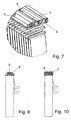
- FIGS. 5 to 7 show a double-row evaporator 1 along the upper side of which the refrigerant is supplied to and removed from the lines 8.
- these lines 8 are present three filled with a cold storage medium cold storage elements 3, which form the cold storage 2, provided.
- the cold storage elements 3 are mounted alternately with the lines 8 on the evaporator side, wherein the height of the cold storage elements 3 is determined approximately by the height of the lines 8, so that no additional space is required.
- the cold storage elements 3 are adapted in shape to the lines 8, so that the largest possible contact area between the cold storage elements 3 and the lines 8 is given.
- the cold storage elements 3 made of aluminum and are firmly soldered to the evaporator 1 and the lines 8.
- the cold storage elements consist of plastic filled with a cold storage medium, so that the attachment of the cold storage elements can take place only after the soldering process.
- the lateral cold storage elements of the second exemplary embodiment are dispensed with and only the middle cold storage element 3 is arranged between the lines 8.
- Fig. 10 shows a fourth embodiment, according to which the cold storage element 3 is formed Mogliedrig side of and between the lines 8, wherein it corresponds to a connected embodiment of the cold accumulator 2 according to the second embodiment.
Landscapes
- Engineering & Computer Science (AREA)
- Physics & Mathematics (AREA)
- Thermal Sciences (AREA)
- Mechanical Engineering (AREA)
- General Engineering & Computer Science (AREA)
- Air-Conditioning For Vehicles (AREA)
Abstract
Description
- Die Erfindung betrifft eine Klimaanlage mit Kältespeicher für ein Kraftfahrzeug gemäß dem Oberbegriff des Anspruches 1.
- Es ist ein Ziel der Kraftfahrzeughersteller, den Kraftstoffverbrauch des Fahrzeugs zu reduzieren. Eine Maßnahme zur Reduzierung des Kraftstoffverbrauchs ist das Abschalten des Motors bei vorübergehendem Stillstand, beispielsweise beim Halten an einer Ampel. Dieses vorübergehende Abschalten des Motors wird auch Idle-stop-Betrieb genannt. Diese Maßnahme wird bei heutigen verbrauchsarmen Fahrzeugen, wie beispielsweise bei dem sogenannten Dreiliter-Fahrzeug, bereits eingesetzt. Bei Fahrzeugen, die über den Idle-stop-Betriebsmodus verfügen, ist im innerstädtischen Verkehr ca. 25-30 % der Fahrzeit der Motor ausgeschaltet.
- Dies ist ein Grund, warum derartige Fahrzeuge nicht mit einer Klimaanlage ausgerüstet sind, denn bei Motorstillstand kann auch ein für eine Klimaanlage notwendiger Kompressor nicht angetrieben werden, so dass im Idle-stop-Betrieb eine Klimaanlage die notwendige Kälteleistung nicht bereitstellen kann.
- In der DE 101 56 944 A1 ist eine Klimaanlage für ein Kraftfahrzeug mit in einem Kältemittelkreis angeordnetem Kompressor und Verdampfer zum Abkühlen von zu konditionierender Luft für den Innenraum offenbart, welche einen zweiten Verdampfer zum Abkühlen der Luft aufweist, der zusätzlich ein Kältespeichermedium enthält, wobei die zu konditionierende Luft wahlweise durch jeden Verdampfer einzeln oder durch beide Verdampfer gemeinsam leitbar ist. Gemäß einer alternativen Ausführungsform ist an Stelle des zweiten Verdampfers der Verdampfer derart ausgebildet, dass er zwei Teilbereiche aufweist, und in einem der beiden Teilbereiche ein Kältespeichermedium enthält, wobei die zu konditionierende Luft wahlweise durch jeden Teilbereich einzeln oder durch beide Teilbereiche gemeinsam leitbar ist. Der Kältemittelspeicher ist hierbei über die gesamte Tiefe des Verdampfers ausgebildet, wobei er zwischen Flachrohren und Wellrippen angeordnet ist. Entsprechende Klimaanlagen lassen jedoch noch Wünsche offen.
- Ausgehend von diesem Stand der Technik ist es Aufgabe der Erfindung eine verbesserte Klimaanlage zur Verfügung zu stellen. Diese Aufgabe wird gelöst durch eine Klimaanlage mit den Merkmalen des Anspruchs 1. Vorteilhafte Ausgestaltungen sind Gegenstand der Unteransprüche.
- Erfindungsgemäß ist eine Klimaanlage für ein Kraftfahrzeug vorgesehen mit einem Verdampfer, welcher zum Abkühlen von zu konditionierender Luft für den Innenraum dient, wobei ein in einem Kältespeicher enthaltenes Kältespeichermedium vorgesehen ist, wobei der Kältespeicher im Bereich mindestens eines Sammelkastens und/oder von Kältemittel-Leitungen, die am Verdampfer vorgesehen sind und der Kältemittelversorgung des Verdampfers dienen, angeordnet ist. Die Anbringung - im Gegensatz zum Stand der Technik - auf mindestens einer Außenseite des Verdampfers, die nicht im Weg der Luftströmung liegt, ermöglicht eine strömungstechnisch optimierte Ausgestaltung. Bevorzugt sind hierbei die normalen Verdampfer und die Verdampfer mit Kältespeicher gleich ausgebildet, so dass die Herstellungskosten relativ gering sind. Ferner ist eine nachträgliche Aufrüstung einfach möglich.
- Beim Verdampfer handelt es sich bevorzugt um einen mindestens zweireihigen Verdampfer. Bevorzugt ist das Kältespeicherelement sich in Längsrichtung erstreckend in einem Mittelbereich zwischen zwei benachbarten Teilen eines zweiteiligen Sammelkastens angeordnet. Das Kältespeicherelement ist in flächiger Anlage an den Sammelkasten.
- Das Kältespeicherelement besteht bevorzugt aus Aluminium, insbesondere innen und/oder außen beschichtetem Aluminium, Kupfer, einer Kupfer-ZinkLegierung, Kunstharz oder Kunststoff. Ein Aluminium-Behälter hat den Vorteil, dass er sich mit den übrigen Teilen des Verdampfers verlöten lässt.
- Das Kältespeicherelement ist bevorzugt mit dem Verdampfer verlötet. Dies ermöglicht eine einfache Herstellung des Verdampfers, wobei das Verlöten mit dem herkömmlichen Verlöten des Verdampfers erfolgt. Das Verlöten hat neben den Vorteilen in Hinblick auf die Herstellung auch Vorteile in Hinblick auf den Wärmeübergang zwischen den mit Hilfe des Lots verbundenen Bereichen des Verdampfers und des Kältespeicherelements. Die Anbringung kann alternativ auch lösbar erfolgen, wobei vorzugsweise eine Wärmeleitpaste die Wärmeübertragung verbessert.
- Ferner können auf der Innenseite, d.h. in Kontakt mit dem Kältespeicherniedium, Beschichtungen zur Begünstigung der Kristallbildung beim Erstarren aufgebracht sein, so dass keine zusätzlichen Kristallbildner im Kaltespeichermedium benötigt werden. Eine Innenbeschichtung schützt zudem den Behälterwerkstoff vor Korrosion durch das Kältespeichermedium. Ebenfalls möglich sind Außenbeschichtungen.
- Beim Speichermedium handelt es sich bevorzugt um ein PCM-Material (phase change material), das bevorzugt kongruent schmelzende Medien, insbesondere Decanol, Tetra-, Penta- oder Hexadecan, LiClO33H2O, wässrige Salzlösungen oder organische Hydrate enthält oder hieraus gebildet ist. Im Speichermedium können auch Keimbildner vorgesehen sein, welche die Kristallbildung beschleunigen.
- Die Phasenumwanldlungstemperatur des Speichermediums liegt vorzugsweise in einem Bereich von 0°C bis 30°C, insbesondere von 2°C bis 15°C, insbesondere bevorzugt von 4°C bis 12°C.
- Im Inneren des Kältespeicherelements können Einlagen, wie Wellrippenbleche, vorzugsweise aus Aluminium, jedoch sind auch andere Metalle oder Kunststoffe geeignet, oder andere Turbulenzeinlagen, wie Vliese oder Gestricke, bspw. aus Kunststoff oder Metall, oder Schäume, bspw. Metallschäume oder Kunststoffschäume, vorgesehen sein. Die Einlagen dienen unter Umständen einer Erhöhung der Festigkeit des Speicherelementes, einer Vergrößerung der wärmeleitenden Kontaktfläche und/oder einer Verkürzung der Wärmeleitwege zwischen dem Speichermedium und der Behälterwand.
- Im Folgenden wird die Erfindung anhand mehrerer Ausführungsbeispiele mit Varianten unter Bezugnahme auf die Zeichnung im Einzelnen erläutert. Es zeigen:
- Fig. 1
- eine perspektivische Ansicht eines Verdampfers mit einem Kältespeicher gemäß dem ersten Ausführungsbeispiel,
- Fig. 2
- eine Seitenansicht des Verdampfers von Fig. 1,
- Fig. 3
- einen Schnitt entlang Linie III-III in Fig. 2,
- Fig. 4
- einen Schnitt entlang Linie VI-VI in Fig. 2,
- Fig. 5
- einen Schnitt quer durch einen Verdampfer gemäß dem zweiten Ausführungsbeispiel,
- Fig. 6
- eine geschnittene Seitenansicht des Verdampfers von Fig. 5,
- Fig. 7
- eine perspektivische geschnittene Explosionsdarstellung des Verdampfer von Fig. 5,
- Fig. 8
- einen Schnitt quer durch einen Verdampfer gemäß dem dritten Ausführungsbeispiel,
- Fig. 9
- eine perspektivische geschnittene Explosionsdarstellung des Verdampfer von Fig. 8, und
- Fig. 10
- einen Schnitt quer durch einen Verdampfer gemäß dem vierten Ausführungsbeispiel.
- Eine Kraftfahrzeug-Klimaanlage zum Temperieren des Kraftfahrzeug-Innenraums mit einem Kältemittel-Kreislauf, von der nur der Verdampfer 1 dargestellt ist, weist, um auch bei einem Motorstopp zumindest über einen kurzen Zeitraum eine ausreichende Kühlleistung zur Verfügung zu stellen, einen Kältespeicher 2 bestehend aus einem Kältespeicherelement 3, welches mit einem Kältespeichermedium gefüllt ist, auf. Das Kältespeicherelement 3 ist durch einen Kunststoff-Behälter gebildet, so dass als Kältespeichermedien auch aggressive Medien, die nicht in Metall-Behälter gefüllt werden können, verwendet werden können. Als Kältespeichermedium, das in Fig. 4 durch eine gekreuzte Schraffur dargestellt ist, dient vorliegend Tetra-, Penta- oder Hexadecan.
- Der Verdampfer 1 weist einen im Wesentlichen herkömmlichen Aufbau mit zwei Reihen von Flachrohren 4 und dazwischen angeordneten Wellrippen 5 auf, die beidseitig in Sammelkästen 6 enden. Die Sammelkästen 6 weisen einen Querschnitt mit zwei U-förmigen Rinnen 7 auf (vgl. Fig. 4). Das Kältespeicherelement 3 ist am oberen Sammelkasten 6 im Bereich zwischen den beiden Rinnen 7 angeordnet, wobei in seiner Gestalt an die Rinnen 7 angepasst ist und oben in etwa gleicher Höhe mit den Rinnen 7 mit einer ebenen Fläche endet, so dass es einen etwa dreieckigförmigen Querschnitt aufweist.
- Die Verdampferrohre 4 weisen auf der Innenseite, das heißt auf der mit dem Kältespeichermedium in Kontakt stehenden Seite, Mikrostrukturen auf. Diese wurden beispielsweise mittels Aufprägen ausgebildet. So kann das Kältemittel des Verdampfers 1 nahezu vollständig in den kältemittelführenden Flachrohren 4 verdampfen und in den Sammelkästen 6, an welchen das Kältespeicherelement 3 angebracht ist, wieder kondensieren. Die Mikrostrukturen ermöglichen eine Erhöhung der übertragbaren Wärmeleistung.
- Im Inneren des durchgehenden Hohlraums des Kältespeicherelements 3 sind gemäß einer nicht in der Zeichnung dargestellten Variante Elemente zur Verhinderung einer Strömungsausbildung und/oder zur Verbesserung des thermischen Kontaktes zwischen dem Speichermedium und der Behälterwand vorgesehen. Derartige Elemente können als Rippenbleche, Drahtgestricke, Metallschäume, Vliese und dergleichen ausgebildet sein.
- Gemäß einer Variante besteht das Kältespeicherelement aus mit einem Kältespeichermedium gefüllten Aluminiumbehälter, die Gestalt entspricht dem des ersten Ausführungsbeispiels, welcher mit dem Verdampfer mitgelötet wird, d.h. es handelt sich hierbei um einen integrierten, fest mit dem Verdampfer verbundenen Kältespeicher. Hierbei ist der Wärmekontakt auf Grund der Lötverbindung besser als der beim zuvor beschriebenen Ausführungsbeispiel, selbst bei Verwendung einer Wärmeleitpaste. Der Aluminium-behälter kann auf seiner Außen- und/oder Innenseite zusätzlich beschichtet sein.
- Die Figuren 5 bis 7 zeigen einen zweireihigen Verdampfer 1 entlang dessen Oberseite das Kältemittel zu- und abführende Leitungen 8 angeordnet sind. Im Bereich dieser Leitungen 8 sind vorliegend drei mit einem Kältespeichermedium gefüllte Kältespeicherelemente 3, welche den Kältespeicher 2 bilden, vorgesehen. Hierbei sind die Kältespeicherelemente 3 abwechselnd mit den Leitungen 8 auf der Verdampferseite angebracht, wobei die Höhe der Kältespeicherelemente 3 etwa durch die Höhe der Leitungen 8 bestimmt ist, so dass kein zusätzlicher Bauraum erforderlich ist. Die Kältespeicherelemente 3 sind in ihrer Gestalt an die Leitungen 8 angepasst, so dass eine möglichst große Kontaktfläche zwischen den Kältespeicherelementen 3 und den Leitungen 8 gegeben ist. Vorliegend bestehen die Kältespeicherelemente 3 aus Aluminium und sind mit dem Verdampfer 1 und den Leitungen 8 fest verlötet.
- Gemäß einer Variante bestehen die Kältespeicherelemente aus mit einem Kältespeichermedium gefüllten Kunststoff, so dass die Anbringung der Kältespeicherelemente erst nach dem Lötvorgang erfolgen kann.
- Gemäß dem in den Figuren 8 und 9 dargestellten dritten Ausführungsbeispiel entfallen die seitlichen Kältespeicherelemente des zweiten Ausführungsbeispiels und es ist ausschließlich das mittlere Kältespeicherelement 3 zwischen den Leitungen 8 angeordnet vorgesehen.
- Fig. 10 zeigt ein viertes Ausführungsbeispiel, gemäß dem das Kältespeicherelement 3 mehrgliedrig seitlich von und zwischen den Leitungen 8 angeordnet ausgebildet ist, wobei es einer verbundenen Ausgestaltung des Kältespeichers 2 gemäß dem zweiten Ausführungsbeispiel entspricht.
Claims (13)
- Klimaanlage mit Kältespeicher, insbesondere für ein Kraftfahrzeug mit einem Kättemitteikreisiauf, der einen Verdampfer (1), welcher zum Abkühlen von zu konditionierender Luft für einen Innenraum insbesondere des Kraftfahrzeugs dient, wobei ein in einem Kältespeicher (2) enthaltenes Kältespeichermedium vorgesehen ist, dadurch gekennzeichnet, dass der Kältespeicher (2) im Bereich mindestens eines Sammelkastens (6) und/oder von Kältemittel-Leitungen, die am Verdampfer (1) vorgesehen sind und der Käitemitteiversorgung des Verdampfers dienen, angeordnet ist.
- Klimaanlage nach Anspruch 1, dadurch gekennzeichnet, dass der Verdampfer (1) ein mehrreihiger Verdampfer ist.
- Klimaanlage nach Anspruch 1 oder 2, dadurch gekennzeichnet, dass das Kältespeicherelement (3) sich in Längsrichtung erstreckend in einem Mittelbereich zwischen zwei benachbarten Teilen eines zweiteiligen Sammelkastens (6) angeordnet ist.
- Klimaanlage nach einem der vorhergehenden Ansprüche, dadurch gekennzeichnet, dass das Kältespeicherelement (3) einen annähernd dreieckigen Querschnitt aufweist, wobei das Kältespeicherelement (3) mit zwei Seiten in flächiger Anlage an mindestens einen Sammelkasten (6) ist.
- Klimaanlage nach einem der vorhergehenden Ansprüche, dadurch gekennzeichnet, dass der Sammelkasten (6) mehrteilig ausgebildet ist, wobei jeder Teil einen Querschnitt mit einer U-förmigen Rinne (7) aufweist und das Kältespeicherelement (3) zwischen zwei U-förmigen Rinnen (7) angeordnet ist.
- Klimaanlage nach einem der vorhergehenden Ansprüche, dadurch gekennzeichnet, dass das Kältespeicherelement (3) an dem Verdampfer (1) und/oder mindestens an einer Kältemittel-Zu- oder -Ableitung (8) des Verdampfers (1) angebracht, insbesondere angeclipst, ist.
- Klimaanlage nach einem der vorhergehenden Ansprüche, dadurch gekennzeichnet, dass das Kältespeicherelement (3) mit dem Verdampfer (1) und/oder mindestens einer Kältemittel-Zu- oder -Ableitung (8) des Verdampfers (1) verlötet ist.
- Klimaanlage nach einem der vorhergehenden Ansprüche, dadurch gekennzeichnet, dass das Kältespeicherelement (3) aus Aluminium, insbesondere beschichtetem Aluminium, besteht.
- Klimaanlage nach einem der vorhergehenden Ansprüche, dadurch gekennzeichnet, dass das Kältespeicherelement (3) eine Beschichtung, insbesondere eine Innenbeschichtung zur Unterstützung der Keimbildung, aufweist.
- Klimaanlage nach einem der vorhergehenden Ansprüche, dadurch gekennzeichnet, dass das Kältespeichermedium durch ein PCM-Material gebildet ist.
- Klimaanlage nach einem der vorhergehenden Ansprüchen, dadurch gekennzeichnet, dass die Phasenumwandlungstemperatur des Speichermediums (3) in einem Bereich von 0°C bis 30°C, insbesondere von 2°C bis 15°C, insbesondere bevorzugt von 4°C bis 12°C, liegt.
- Klimaanlage nach einem der vorhergehenden Ansprüchen, dadurch gekennzeichnet, dass das Kältespeicherelement (3) eine Innenfläche mit Mikrostrukturen aufweist.
- Klimaanlage nach einem der vorhergehenden Ansprüche, dadurch gekennzeichnet, dass im Kältespeicherelement mindestens eine Einlage angeordnet ist.
Applications Claiming Priority (1)
| Application Number | Priority Date | Filing Date | Title |
|---|---|---|---|
| DE102004055343A DE102004055343A1 (de) | 2004-11-16 | 2004-11-16 | Klimaanlage mit Kältespeicher |
Publications (3)
| Publication Number | Publication Date |
|---|---|
| EP1657090A2 true EP1657090A2 (de) | 2006-05-17 |
| EP1657090A3 EP1657090A3 (de) | 2007-12-05 |
| EP1657090B1 EP1657090B1 (de) | 2011-01-12 |
Family
ID=35788738
Family Applications (1)
| Application Number | Title | Priority Date | Filing Date |
|---|---|---|---|
| EP05024814A Expired - Lifetime EP1657090B1 (de) | 2004-11-16 | 2005-11-14 | Klimaanlage mit Kältespeicher |
Country Status (2)
| Country | Link |
|---|---|
| EP (1) | EP1657090B1 (de) |
| DE (2) | DE102004055343A1 (de) |
Cited By (7)
| Publication number | Priority date | Publication date | Assignee | Title |
|---|---|---|---|---|
| EP2653329A1 (de) * | 2012-04-20 | 2013-10-23 | Delphi Technologies, Inc. | Verdampfer mit Phasenwechselmaterial für Thermosyphon-Betrieb |
| FR3001184A1 (fr) * | 2013-01-24 | 2014-07-25 | Valeo Systemes Thermiques | Dispositif de ventilation, chauffage et/ou climatisation pour vehicule automobile |
| WO2014187734A1 (fr) * | 2013-05-22 | 2014-11-27 | Valeo Systemes Thermiques | Dissipateur de chaleur et circuit de gestion thermique associe |
| WO2016170751A1 (ja) * | 2015-04-21 | 2016-10-27 | 株式会社デンソー | 蓄冷熱交換器 |
| FR3056722A1 (fr) * | 2016-09-29 | 2018-03-30 | Valeo Systemes Thermiques | Echangeur thermique comprenant un materiau a changement de phase |
| WO2018060646A1 (fr) * | 2016-09-28 | 2018-04-05 | Valeo Systemes Thermiques | Boite collectrice comprenant un matériau à changement de phase et échangeur de chaleur comprenant une telle boite collectrice |
| JP2019152377A (ja) * | 2018-03-02 | 2019-09-12 | 株式会社デンソー | 熱交換器 |
Citations (1)
| Publication number | Priority date | Publication date | Assignee | Title |
|---|---|---|---|---|
| DE10156944A1 (de) | 2001-01-05 | 2002-07-11 | Behr Gmbh & Co | Klimaanlage für ein Kraftfahrzeug |
Family Cites Families (5)
| Publication number | Priority date | Publication date | Assignee | Title |
|---|---|---|---|---|
| DE19615511A1 (de) * | 1996-04-19 | 1997-10-23 | Wilo Gmbh | Kühler eines Kraftfahrzeugverbrennungsmotors |
| JP3972501B2 (ja) * | 1999-01-18 | 2007-09-05 | 株式会社デンソー | 蓄熱用熱交換装置および車両用空調装置 |
| FR2824388A1 (fr) * | 2001-05-07 | 2002-11-08 | Italinnova Sas | Generateur de froid pour installation de climatisation de vehicule |
| DE10247262A1 (de) * | 2002-10-10 | 2004-04-22 | Behr Gmbh & Co. | Verfahren zur Verdampfungstemperaturregelung bei einer Klimaanlage |
| DE10308254A1 (de) * | 2003-02-25 | 2004-09-02 | Behr Gmbh & Co. Kg | Klimaanlage für ein Fahrzeug und zugehöriges Betriebsverfahren |
-
2004
- 2004-11-16 DE DE102004055343A patent/DE102004055343A1/de not_active Withdrawn
-
2005
- 2005-11-14 DE DE502005010830T patent/DE502005010830D1/de not_active Expired - Lifetime
- 2005-11-14 EP EP05024814A patent/EP1657090B1/de not_active Expired - Lifetime
Patent Citations (1)
| Publication number | Priority date | Publication date | Assignee | Title |
|---|---|---|---|---|
| DE10156944A1 (de) | 2001-01-05 | 2002-07-11 | Behr Gmbh & Co | Klimaanlage für ein Kraftfahrzeug |
Cited By (9)
| Publication number | Priority date | Publication date | Assignee | Title |
|---|---|---|---|---|
| EP2653329A1 (de) * | 2012-04-20 | 2013-10-23 | Delphi Technologies, Inc. | Verdampfer mit Phasenwechselmaterial für Thermosyphon-Betrieb |
| FR3001184A1 (fr) * | 2013-01-24 | 2014-07-25 | Valeo Systemes Thermiques | Dispositif de ventilation, chauffage et/ou climatisation pour vehicule automobile |
| WO2014187734A1 (fr) * | 2013-05-22 | 2014-11-27 | Valeo Systemes Thermiques | Dissipateur de chaleur et circuit de gestion thermique associe |
| FR3006044A1 (fr) * | 2013-05-22 | 2014-11-28 | Valeo Systemes Thermiques | Dissipateur de chaleur et circuit de gestion thermique associe. |
| WO2016170751A1 (ja) * | 2015-04-21 | 2016-10-27 | 株式会社デンソー | 蓄冷熱交換器 |
| JP2016203766A (ja) * | 2015-04-21 | 2016-12-08 | 株式会社デンソー | 蓄冷熱交換器 |
| WO2018060646A1 (fr) * | 2016-09-28 | 2018-04-05 | Valeo Systemes Thermiques | Boite collectrice comprenant un matériau à changement de phase et échangeur de chaleur comprenant une telle boite collectrice |
| FR3056722A1 (fr) * | 2016-09-29 | 2018-03-30 | Valeo Systemes Thermiques | Echangeur thermique comprenant un materiau a changement de phase |
| JP2019152377A (ja) * | 2018-03-02 | 2019-09-12 | 株式会社デンソー | 熱交換器 |
Also Published As
| Publication number | Publication date |
|---|---|
| DE102004055343A1 (de) | 2006-05-18 |
| EP1657090A3 (de) | 2007-12-05 |
| DE502005010830D1 (de) | 2011-02-24 |
| EP1657090B1 (de) | 2011-01-12 |
Similar Documents
| Publication | Publication Date | Title |
|---|---|---|
| EP1984195B1 (de) | Wärmeüberträger mit kältespeicher | |
| EP1996890B1 (de) | Wärmeübertrager mit kältespeicher | |
| EP1984196B1 (de) | Wärmeübertrager, insbesondere mit kältespeicher | |
| EP1967396A1 (de) | Klimaanlage mit Kältespeicher und Verfahren zum Betreiben einer derartigen Klimaanlage | |
| EP1657090B1 (de) | Klimaanlage mit Kältespeicher | |
| DE19739389C2 (de) | Eisspeicher-Element | |
| WO2013029769A1 (de) | Verdampfer-waermetauscher-einheit | |
| EP1814750B1 (de) | Klimaanlage mit kältespeicher | |
| EP1892491A2 (de) | Einheit, aufweisend einen Gaskühler und einen inneren Wärmetauscher, und Wärmetauscher | |
| EP1814751B1 (de) | Klimaanlage mit kältespeicher | |
| DE102006041286A1 (de) | System zur Standklimatisierung und Verfahren zum Betreiben eines derartigen Systems | |
| EP2442058B1 (de) | Wärmeübertrager mit Kältespeicherrohren | |
| EP1657088B1 (de) | Wärmeübertrager mit Kältespeicher | |
| DE102004052979A1 (de) | Klimaanlage mit Kältespeicher | |
| DE102004055341A1 (de) | Wärmetauscher mit Kältespeicherelement | |
| DE102006042789A1 (de) | Klimaanalge mit Kältespeicher und Verfahren zum Betreiben einer solchen | |
| DE19839995C2 (de) | Kunststoff-Eisspeicherelement | |
| DE112018001417B4 (de) | Verdampfer eines Klimakreislaufs | |
| DE19839992C2 (de) | Eisspeicherelement-Baueinheit mit mehreren Profilkörper-Eisspeicherelementen | |
| EP1814749B1 (de) | Kältespeicher-akkumulator |
Legal Events
| Date | Code | Title | Description |
|---|---|---|---|
| PUAI | Public reference made under article 153(3) epc to a published international application that has entered the european phase |
Free format text: ORIGINAL CODE: 0009012 |
|
| AK | Designated contracting states |
Kind code of ref document: A2 Designated state(s): AT BE BG CH CY CZ DE DK EE ES FI FR GB GR HU IE IS IT LI LT LU LV MC NL PL PT RO SE SI SK TR |
|
| AX | Request for extension of the european patent |
Extension state: AL BA HR MK YU |
|
| PUAL | Search report despatched |
Free format text: ORIGINAL CODE: 0009013 |
|
| AK | Designated contracting states |
Kind code of ref document: A3 Designated state(s): AT BE BG CH CY CZ DE DK EE ES FI FR GB GR HU IE IS IT LI LT LU LV MC NL PL PT RO SE SI SK TR |
|
| AX | Request for extension of the european patent |
Extension state: AL BA HR MK YU |
|
| 17P | Request for examination filed |
Effective date: 20080605 |
|
| 17Q | First examination report despatched |
Effective date: 20080709 |
|
| AKX | Designation fees paid |
Designated state(s): CZ DE ES FR GB |
|
| GRAP | Despatch of communication of intention to grant a patent |
Free format text: ORIGINAL CODE: EPIDOSNIGR1 |
|
| GRAS | Grant fee paid |
Free format text: ORIGINAL CODE: EPIDOSNIGR3 |
|
| GRAA | (expected) grant |
Free format text: ORIGINAL CODE: 0009210 |
|
| AK | Designated contracting states |
Kind code of ref document: B1 Designated state(s): CZ DE ES FR GB |
|
| REG | Reference to a national code |
Ref country code: GB Ref legal event code: FG4D Free format text: NOT ENGLISH |
|
| REF | Corresponds to: |
Ref document number: 502005010830 Country of ref document: DE Date of ref document: 20110224 Kind code of ref document: P |
|
| REG | Reference to a national code |
Ref country code: DE Ref legal event code: R096 Ref document number: 502005010830 Country of ref document: DE Effective date: 20110224 |
|
| PG25 | Lapsed in a contracting state [announced via postgrant information from national office to epo] |
Ref country code: ES Free format text: LAPSE BECAUSE OF FAILURE TO SUBMIT A TRANSLATION OF THE DESCRIPTION OR TO PAY THE FEE WITHIN THE PRESCRIBED TIME-LIMIT Effective date: 20110423 |
|
| PLBE | No opposition filed within time limit |
Free format text: ORIGINAL CODE: 0009261 |
|
| STAA | Information on the status of an ep patent application or granted ep patent |
Free format text: STATUS: NO OPPOSITION FILED WITHIN TIME LIMIT |
|
| PG25 | Lapsed in a contracting state [announced via postgrant information from national office to epo] |
Ref country code: CZ Free format text: LAPSE BECAUSE OF FAILURE TO SUBMIT A TRANSLATION OF THE DESCRIPTION OR TO PAY THE FEE WITHIN THE PRESCRIBED TIME-LIMIT Effective date: 20110112 |
|
| 26N | No opposition filed |
Effective date: 20111013 |
|
| PGFP | Annual fee paid to national office [announced via postgrant information from national office to epo] |
Ref country code: FR Payment date: 20111130 Year of fee payment: 7 |
|
| REG | Reference to a national code |
Ref country code: DE Ref legal event code: R097 Ref document number: 502005010830 Country of ref document: DE Effective date: 20111013 |
|
| GBPC | Gb: european patent ceased through non-payment of renewal fee |
Effective date: 20111114 |
|
| PG25 | Lapsed in a contracting state [announced via postgrant information from national office to epo] |
Ref country code: GB Free format text: LAPSE BECAUSE OF NON-PAYMENT OF DUE FEES Effective date: 20111114 |
|
| REG | Reference to a national code |
Ref country code: FR Ref legal event code: ST Effective date: 20130731 |
|
| PG25 | Lapsed in a contracting state [announced via postgrant information from national office to epo] |
Ref country code: FR Free format text: LAPSE BECAUSE OF NON-PAYMENT OF DUE FEES Effective date: 20121130 |
|
| REG | Reference to a national code |
Ref country code: DE Ref legal event code: R082 Ref document number: 502005010830 Country of ref document: DE Representative=s name: GRAUEL, ANDREAS, DIPL.-PHYS. DR. RER. NAT., DE |
|
| REG | Reference to a national code |
Ref country code: DE Ref legal event code: R082 Ref document number: 502005010830 Country of ref document: DE Representative=s name: GRAUEL, ANDREAS, DIPL.-PHYS. DR. RER. NAT., DE Effective date: 20150303 Ref country code: DE Ref legal event code: R081 Ref document number: 502005010830 Country of ref document: DE Owner name: MAHLE INTERNATIONAL GMBH, DE Free format text: FORMER OWNER: BEHR GMBH & CO. KG, 70469 STUTTGART, DE Effective date: 20150303 |
|
| PGFP | Annual fee paid to national office [announced via postgrant information from national office to epo] |
Ref country code: DE Payment date: 20181203 Year of fee payment: 14 |
|
| REG | Reference to a national code |
Ref country code: DE Ref legal event code: R119 Ref document number: 502005010830 Country of ref document: DE |
|
| PG25 | Lapsed in a contracting state [announced via postgrant information from national office to epo] |
Ref country code: DE Free format text: LAPSE BECAUSE OF NON-PAYMENT OF DUE FEES Effective date: 20200603 |