EP1656885B1 - Device for performing a neuropsychological test - Google Patents
Device for performing a neuropsychological test Download PDFInfo
- Publication number
- EP1656885B1 EP1656885B1 EP05024511A EP05024511A EP1656885B1 EP 1656885 B1 EP1656885 B1 EP 1656885B1 EP 05024511 A EP05024511 A EP 05024511A EP 05024511 A EP05024511 A EP 05024511A EP 1656885 B1 EP1656885 B1 EP 1656885B1
- Authority
- EP
- European Patent Office
- Prior art keywords
- pin
- switch
- electromagnet
- person
- fingertip
- Prior art date
- Legal status (The legal status is an assumption and is not a legal conclusion. Google has not performed a legal analysis and makes no representation as to the accuracy of the status listed.)
- Not-in-force
Links
Images


Classifications
-
- A—HUMAN NECESSITIES
- A61—MEDICAL OR VETERINARY SCIENCE; HYGIENE
- A61B—DIAGNOSIS; SURGERY; IDENTIFICATION
- A61B5/00—Measuring for diagnostic purposes; Identification of persons
- A61B5/40—Detecting, measuring or recording for evaluating the nervous system
-
- A—HUMAN NECESSITIES
- A61—MEDICAL OR VETERINARY SCIENCE; HYGIENE
- A61B—DIAGNOSIS; SURGERY; IDENTIFICATION
- A61B5/00—Measuring for diagnostic purposes; Identification of persons
- A61B5/0048—Detecting, measuring or recording by applying mechanical forces or stimuli
- A61B5/0053—Detecting, measuring or recording by applying mechanical forces or stimuli by applying pressure, e.g. compression, indentation, palpation, grasping, gauging
-
- A—HUMAN NECESSITIES
- A61—MEDICAL OR VETERINARY SCIENCE; HYGIENE
- A61B—DIAGNOSIS; SURGERY; IDENTIFICATION
- A61B5/00—Measuring for diagnostic purposes; Identification of persons
- A61B5/16—Devices for psychotechnics; Testing reaction times ; Devices for evaluating the psychological state
- A61B5/162—Testing reaction times
Definitions
- the invention relates to a device for performing a neuropsychological test with a switch, which comprises a movable pin, with which a stimulus on a fingertip of a person to be examined is exercisable.
- the DE 196 33 866 A1 shows a corresponding device in which a person must press as quickly as possible for a period of 15 seconds with the right and / or left index finger one or two morse buttons as often as possible.
- the morse key is assigned a pressure sensor in order to detect the tactile pressure in addition to the tactile frequency.
- the specification of a certain tactile rhythm or the operation of different Morse keys in response to a signal is not disclosed.
- a tapping device comprising a plurality of intersecting, mutually insulated tracks. Depending on which tracks are controlled via a random generator voltage is applied, this intersection is identified as the default Tappingort.
- This tapping location must be determined by the person For example, with a fingertip, pressed, the pressing is detected electromagnetically. Also, the pressure exerted by the fingertip can be detected.
- the tapping device has the disadvantage that it must be made relatively large area to identify different tapping locations.
- a neurological test device in which, for example via colored LEDs, a signal is transmitted to a person to be examined, which then has to touch, inter alia, a touch-sensitive screen.
- the information is transmitted from the eye to the brain, which is why no information is transmitted from the fingertips to the brain.
- each finger is associated with a switch, each comprising a movable pin.
- the switches may be driven by a common controller to respectively move the pins to exert a stimulus on the person's fingertips.
- the person in turn may, for example, when an irritation of a finger was done by one of the pins, act on the pen, which is detected by the controller.
- the switch can only be actuated if the pin has previously been moved to an extended position. This is disadvantageous in that an incorrect operation of a switch with retracted pin with the device is not detectable, since the arranged in a retracted position pin can not be further depressed.
- the object is achieved in that the switch is associated with an operable with the fingertip pressure transducer, which is acted upon independently of the position of the pin.
- the core idea of the invention is that the irritation of the skin of a fingertip of the person to be examined in a conventional manner via a movable between two positions pin, preferably a metal pin occurs.
- the fingertip is irritated, for example, by the displacement of the pin from a retracted to an extended position.
- the switch or the entire device comprises a pressure transducer, which is associated with the switch or the pin so that it can be actuated by the same fingertip that is irritated by the pin.
- the pin and the pressure transducer can be arranged in any desired manner, but preferably as described below.
- the device or the switch is assigned a control in order to exert on the one hand with the switch or the stylus one or more stimuli in a desired temporal sequence on the fingertip and an actuation of the pressure transducer by the fingertip capture.
- the controller is preferably designed such that the measurement results, ie in addition to the activation of the pen, the operation of the pressure transducer, read out as a function of time from the controller and is preferably evaluated on a PC with a suitable program.
- the advantage of the invention is that a reaction of the person to be examined at any time with the device can be detected, since the pressure transducer can be pressed or pressed regardless of the position of the pen of the fingertip, so it is not erforderilch, down to the pen Press, which also results in a relatively short reaction time.
- the reaction times i. H. the time between stimulation of the fingertip and actuation of the pressure transducer can be detected with the device.
- error rates, d. H. to detect a faulty operation of the pressure transducer, as well as their time course, since with increasing test duration usually a fatigue of the person and concomitantly an increase in the error rate occurs.
- the pressure transducer is designed in the form of a touch plate and the pin extends through a recess of the touch panel.
- the touch plate is in the axial direction of the pen, in which it is also moved to stimulate the fingertip depressible to detect the reaction of the person to the irritation of the pen by this depression.
- the touch panel may be formed as a round disc made of metal and / or plastic with a central recess for the pin, wherein the diameter of the touch panel corresponds approximately to the size of a fingertip.
- the pressure with which the pressure transducer is actuated by the fingertip can be detected, wherein the size of the pressure can be measured, for example, via a piezoelectric element assigned to the touch plate.
- the force exerted by the fingertip on the touch plate also in the time course of depression can be detected in order to derive further sensu-motor information from this.
- the device comprises four or five switches with a movable pin, each associated with a pressure transducer, the switches are ergonomically arranged so that in a relaxed hand position of the person's fingertips come to rest on the switches.
- the switches can be arranged on an upper side of a housing of the device in order to operate the switches comfortably with the fingertips.
- the switches can be made flush with this surface or slightly projecting over the surface.
- the device is preferably constructed of two essentially mirror-symmetrical similar housings with switches to stimulate the fingertips of both hands of the person and to derive sensory-motor conclusions from this.
- the arranged in two separate housings eight or ten switches are of course controlled by a common control to obtain, for example, by an irritation of the fingertips of the right hand statements about the capabilities of the left hemisphere and vice versa.
- an electromagnet which is driven, for example via a relay, wherein the pin is pulled out by the magnetic field upon activation of the electromagnet.
- the touch panel is moved by the pressure of a fingertip together with the electromagnet, wherein the movement is parallel to the axial direction of movement of the pin.
- the touch plate and the electromagnet are mounted in a correspondingly designed guide. After reaching an end position, the force exerted by the fingertip force is absorbed by the guide and / or the housing, which is why a destructive or damaging overstroke is excluded.
- the pressure transducer and optionally the electromagnet together of a preferably as a micro key spring designed spring loaded with a restoring force to move the pressure transducer, for example, in a top of a housing arranged switch back up.
- the device further signal means are assigned to transmit optical and / or acoustic signals or stimuli. These may be, for example, light sources to generate different light signals, or a loudspeaker to output voice messages, sounds or the like.
- the voice message can be output that, despite the irritation of a finger, there should be no reaction. This allows conclusions to be drawn on the processing of these signals in the brain or on the forwarding of the corresponding commands in the brain, in particular from the error rate occurring here.
- the device can be controlled in different operating modes.
- a fingertip pressure transducer may be actuated as often as possible within a predetermined time period or according to a rhythm dictated by the stylus.
- continuous stimulation for example by vibration of the strift, is also possible for the examination of attention.
- either only a single finger or several fingers can be detected consecutively.
- the number of taps ie a press, for the given total duration, the number of taps per period for determination a trajectory, the time interval of two successive taps, the time course and the rhythm and an error rate are recorded, for example, at the same time recording the taps of two hands, the manual coordination, the rhythmicity and stability of the finger motor and the motor fatigue in temporal To measure course and to compare the two halves of the brain with each other and to be able to locate a possibly existing brain dysfunction. It goes without saying that an EEG of the patient can be recorded at the same time.
- the device is provided with a connection point, via which the activation of the pin or a signal of the pressure sensor is forwarded to the EEG.
- the response time may be detected by detecting the time between the exercise of the stimulus by the moving stylus and the actuation of the pressure transducer.
- the patient may be indicated, for example via a light signal, that, although irritated, he should not actuate the pressure transducer so as to measure a so-called election reaction time. It is also possible, for example, to irritate a finger of the left hand and to require the person to operate the pressure transducer with the corresponding finger of the right hand and vice versa. Interhemispheric transmission processes can be measured to detect a brain dysfunction affecting the interhemispheric connection system.
- the motor and tactile performance characteristics of individual fingers isolated and differentiated detected become.
- the finger and hand motor skills of a person, in particular after a brain injury can be trained with the device.
- the switch 1 consists essentially of a metallic, provided with an end tip 11 pin 2, which is disposed within an electromagnet 3, wherein the electromagnet 3 is controlled such that the pin 2 in its axial direction from a retracted to an extended position is relocatable. In this extended position, the pin 2 is perpendicular to the top over the switch 1 and irritated with its tip 11, the skin of resting on the switch 1 fingertip of a person to be examined.
- the switch 1 is associated with a pressure sensor, which is designed here in the form of an annular contact plate 4 with a central recess for the pin 2. If the pressure transducer or the touch plate 4 is actuated, the touch plate 4 is displaced together with the pin 2 and the electromagnet 3 in the axial direction, as indicated by the double arrow A, down.
- the electromagnet 3 is arranged displaceably in a guide 5 which is formed in two parts here.
- the touch plate 4 can be operated independently of the position of the pin 2.
- the switch 1 on an acceleration block 6 to the movement of the electromagnet 3 and the touch panel 4 to a arranged in a holder 7 micro switch 8 to transmit.
- the acceleration block 6 a movement of the electromagnet 3 and the touch plate 4 can be attenuated.
- the acceleration block 6 allows, depending on its configuration, a variation of the terminal speed of the pin 2 and thus of the triggered pulse.
- the microswitch 8 has a spring to relocate after releasing the touch plate 4 and the electromagnet 3 back up to the original position.
- the guide 5 and the holder 7 are preferably made of metal and / or plastic.
- the signals of the microswitch 8 are read out via a suitable controller, which is implemented in hardware and / or software, and the electromagnet 3 is controlled in a desired manner by means of the controller in order to carry out different neuropsychological tests with the apparatus.
- the control can vary in such a way that single pulses, multiple impulses up to continuous pulses (vibration) of the pin 2 are possible.
- the pulse of the pin 2 can also be influenced by an adaptation of the turn-on time or a change in the operating voltage of the electromagnet 3 in a wide range down to the Tastschwelle.
- the device consists essentially of two mirror-symmetrical housings 9, on the tops of which a plurality of switches 1 are distributed in an ergonomic manner in order to stimulate four fingers of one hand and to detect the reactions thereto.
- a fifth switch 1 for the thumb can also be provided in the housings 9 in each case.
- lines 10 are led out for power supply and for driving the switch 1 and for reading the measurement data, the evaluation and control preferably with a corresponding program via a PC.
Landscapes
- Health & Medical Sciences (AREA)
- Life Sciences & Earth Sciences (AREA)
- Engineering & Computer Science (AREA)
- Animal Behavior & Ethology (AREA)
- Public Health (AREA)
- Veterinary Medicine (AREA)
- Biophysics (AREA)
- Pathology (AREA)
- Physics & Mathematics (AREA)
- Biomedical Technology (AREA)
- Heart & Thoracic Surgery (AREA)
- Medical Informatics (AREA)
- Molecular Biology (AREA)
- Surgery (AREA)
- General Health & Medical Sciences (AREA)
- Hospice & Palliative Care (AREA)
- Neurosurgery (AREA)
- Physiology (AREA)
- Child & Adolescent Psychology (AREA)
- Developmental Disabilities (AREA)
- Educational Technology (AREA)
- Neurology (AREA)
- Psychiatry (AREA)
- Psychology (AREA)
- Social Psychology (AREA)
- Measurement Of The Respiration, Hearing Ability, Form, And Blood Characteristics Of Living Organisms (AREA)
- Acyclic And Carbocyclic Compounds In Medicinal Compositions (AREA)
- Finger-Pressure Massage (AREA)
Abstract
Description
Die Erfindung bezieht sich auf eine Vorrichtung zur Durchführung eines neuropsychologischen Tests mit einem Schalter, der einen bewegbaren Stift umfasst, mit dem ein Reiz auf eine Fingerspitze einer zu untersuchenden Person ausübbar ist.The invention relates to a device for performing a neuropsychological test with a switch, which comprises a movable pin, with which a stimulus on a fingertip of a person to be examined is exercisable.
Zur systematischen Analyse des normalen oder durch eine Hirnschädigung beeinträchtigten sensu-motorischen Reaktionssystems von Personen mit Hilfe einer standardisierten und reproduzierbaren Messtechnik werden unterschiedliche Vorrichtungen verwendet. Mit quantifizierbaren und reproduzierbaren Messergebnissen, die mit den Vorrichtungen ermittelt werden, können Rückschlüsse auf die funktionale Effizienz, Integrität und Reaktivität des Gehirns bzw. bestimmter Hirnregionen, die in einem engen Bezug zu den untersuchten sensu-motorischen Hirnregionen stehen, gezogen werden. Dies sind insbesondere die Frontal- und Parietalregionen der beiden Hemisphären. Hieraus können gegenwärtige oder zukünftige Verhaltensweisen der getesteten Person erklärt oder vorhergesagt werden bzw. Rehabilitationsmaßnahmen zur Behebung einer Störung festgelegt werden.For the systematic analysis of the normal or brain damage impaired sensu-motor response system of persons using a standardized and reproducible measurement technique different devices are used. With quantifiable and reproducible measurement results, which are determined with the devices, conclusions can be drawn on the functional efficiency, integrity and reactivity of the brain or specific brain regions that are closely related to the sensory-motor brain regions examined. These are in particular the frontal and parietal regions of the two hemispheres. From this, current or future behaviors of the tested person can be explained or predicted, or rehabilitation measures can be established to remedy a disorder.
Es werden normale, nicht hirngeschädigte Personen untersucht, um für jede Altersgruppe bzw. jedes Geschlecht durchschnittliche spezifische Leistungsmerkmale und Verhaltensaspekte zu ermitteln, wobei auch Einflüsse von Medikamenten, Alkohol oder dergleichen im Rahmen einer Leistungsmessung erfasst werden können. Im Weiteren kann bei einer vorliegenden Hirnschädigung, die z. B. durch einen Hirninfarkt, eine traumatische Hirnschädigung, einen Hirntumor oder eine degenerative Hirnveränderung, wie Morbus Alzheimer, verursacht wurde, das funktionale Potential der Person erfasst werden. Ebenso können zerebrale Korrelate psychiatrischer Erkrankungen, wie Schizophrenie oder Depression, festgestellt und entsprechende Rehabilitationsmaßnahmen festgelegt werden.Normal, non-brain-injured persons are examined in order to determine average specific performance characteristics and behavioral aspects for each age group or gender, whereby also influences of medicaments, alcohol or the like can be detected within the scope of a performance measurement. Furthermore, in a present brain damage, the z. B. caused by a cerebral infarction, traumatic brain injury, a brain tumor or a degenerative brain change, such as Alzheimer's disease, the functional potential of the person are detected. Similarly, cerebral correlates of psychiatric disorders, such as schizophrenia or depression, can be identified and appropriate rehabilitation measures established.
Die
Im Weiteren beschreibt die
Des Weiteren ist aus der
Ferner beschreibt die
Es ist Aufgabe der Erfindung, eine Vorrichtung zur Durchführung eines neuropsychologischen Tests der eingangs genannten Art zu schaffen, mit der in einfacher Weise eine neuropsychologische Untersuchung durchgeführt werden kann, wobei auch eine unabsichtliche Betätigung bzw. eine fehlerhafte Betätigung eines Schalters der Vorrichtung erfasst werden kann.It is an object of the invention to provide an apparatus for performing a neuropsychological test of the type mentioned, with the neuropsychological examination can be carried out in a simple manner, and also an accidental operation or a faulty operation of a switch of the device can be detected.
Erfindungsgemäß wird die Aufgabe dadurch gelöst, dass dem Schalter ein mit der Fingerspitze betätigbarer Druckaufnehmer zugeordnet ist, der unabhängig von der Position des Stiftes beaufschlagbar ist.According to the invention the object is achieved in that the switch is associated with an operable with the fingertip pressure transducer, which is acted upon independently of the position of the pin.
Der Kerngedanke der Erfindung besteht darin, dass die Reizung der Haut einer Fingerspitze der zu untersuchenden Person in an sich bekannter Weise über einen zwischen zwei Positionen bewegbaren Stift, vorzugsweise ein Metallstift, erfolgt. Hierbei wird die Fingerspitze beispielsweise durch die Verlagerung des Stifts von einer eingezogenen in eine ausgezogene Position gereizt. Des Weiteren umfasst der Schalter bzw. die gesamte Vorrichtung einen Druckaufnehmer, der dem Schalter bzw. dem Stift derart zugeordnet ist, dass er von der gleichen Fingerspitze, die von dem Stift gereizt wird, betätigbar ist. Dabei können der Stift und der Druckaufnehmer in an sich beliebiger Weise, bevorzugt aber wie im Folgenden beschrieben, angeordnet werden. Hierbei ist es für den Fachmann ersichtlich, dass der Vorrichtung bzw. dem Schalter eine Steuerung zugeordnet ist, um einerseits mit dem Schalter bzw. dem Stift einen oder mehrere Reize in einer gewünschten zeitlichen Abfolge auf die Fingerspitze auszuüben sowie eine Betätigung des Druckaufnehmers durch die Fingerspitze zu erfassen. Dabei ist die Steuerung vorzugsweise derart ausgelegt, dass die Messergebnisse, d. h. neben der Ansteuerung des Stifts die Betätigung des Druckaufnehmers, in Abhängigkeit von der Zeit aus der Steuerung ausgelesen und vorzugsweise an einem PC mit einem hierfür geeigneten Programm ausgewertet wird.The core idea of the invention is that the irritation of the skin of a fingertip of the person to be examined in a conventional manner via a movable between two positions pin, preferably a metal pin occurs. Here, the fingertip is irritated, for example, by the displacement of the pin from a retracted to an extended position. Furthermore, the switch or the entire device comprises a pressure transducer, which is associated with the switch or the pin so that it can be actuated by the same fingertip that is irritated by the pin. In this case, the pin and the pressure transducer can be arranged in any desired manner, but preferably as described below. In this case, it is obvious to the person skilled in the art that the device or the switch is assigned a control in order to exert on the one hand with the switch or the stylus one or more stimuli in a desired temporal sequence on the fingertip and an actuation of the pressure transducer by the fingertip capture. In this case, the controller is preferably designed such that the measurement results, ie in addition to the activation of the pen, the operation of the pressure transducer, read out as a function of time from the controller and is preferably evaluated on a PC with a suitable program.
Der Vorteil der Erfindung liegt darin, dass eine Reaktion der zu untersuchenden Person jederzeit mit der Vorrichtung erfassbar ist, da der Druckaufnehmer unabhängig von der Position des Stifts von der Fingerspitze betätigt bzw. gedrückt werden kann, es also nicht erforderilch ist, den Stift nieder zu drücken, woraus auch eine verhältnismäßig kurze Reaktionszeit resultiert. Insbesondere ist es möglich, eine Beaufschlagung des Druckaufnehmers zu erfassen, auch wenn vorher der Stift die Fingerspitze nicht gereizt hat. Hierbei ist es nicht notwendig, die Fingerspitze oder sogar den ganzen Finger nach erfolgter Reizung an eine andere Position zu bewegen, um den Druckaufnehmer zu betätigen. Es versteht sich, dass die Reaktionszeiten, d. h. die Zeitspanne zwischen dem Reizen der Fingerspitze und dem Betätigen des Druckaufnehmers, mit der Vorrichtung erfasst werden können. Ebenso ist es möglich, Fehlerquoten, d. h. eine fehlerhafte Betätigung des Druckaufnehmers, sowie deren zeitliche Verläufe zu erfassen, da bei zunehmender Testdauer üblicherweise eine Ermüdung der Person und damit einhergehend eine Erhöhung der Fehlerquote auftritt.The advantage of the invention is that a reaction of the person to be examined at any time with the device can be detected, since the pressure transducer can be pressed or pressed regardless of the position of the pen of the fingertip, so it is not erforderilch, down to the pen Press, which also results in a relatively short reaction time. In particular, it is possible to detect a pressurization of the pressure transducer, even if previously the pen has not irritated the fingertip. In this case, it is not necessary to move the fingertip or even the whole finger after the irritation to another position to operate the pressure transducer. It is understood that the reaction times, i. H. the time between stimulation of the fingertip and actuation of the pressure transducer can be detected with the device. Likewise, it is possible error rates, d. H. to detect a faulty operation of the pressure transducer, as well as their time course, since with increasing test duration usually a fatigue of the person and concomitantly an increase in the error rate occurs.
Bevorzugt ist der Druckaufnehmer in Form einer Tastplatte ausgebildet und der Stift erstreckt sich durch eine Ausnehmung der Tastplatte. Die Tastplatte ist in axialer Richtung des Stifts, in der dieser auch zur Reizung der Fingerspitze bewegt wird, niederdrückbar, um durch dieses Niederdrücken die Reaktion der Person auf die Reizung durch den Stift zu erfassen. Die Tastplatte kann als runde Scheibe aus Metall und/oder Kunststoff mit einer mittigen Ausnehmung für den Stift ausgeformt sein, wobei der Durchmesser der Tastplatte ungefähr der Größe einer Fingerspitze entspricht.Preferably, the pressure transducer is designed in the form of a touch plate and the pin extends through a recess of the touch panel. The touch plate is in the axial direction of the pen, in which it is also moved to stimulate the fingertip depressible to detect the reaction of the person to the irritation of the pen by this depression. The touch panel may be formed as a round disc made of metal and / or plastic with a central recess for the pin, wherein the diameter of the touch panel corresponds approximately to the size of a fingertip.
In Ausgestaltung ist der Druck, mit dem der Druckaufnehmer von der Fingerspitze betätigt wird, erfassbar, wobei die Größe des Drucks beispielsweise über ein der Tastplatte zugeordnetes Piezoelement gemessen werden kann. Somit kann die Kraft, die von der Fingerspitze auf die Tastplatte ausgeübt wird, auch im zeitlichen Verlauf des Niederdrückens erfasst werden, um hieraus weitere sensu-motorische Informationen ableiten zu können.In an embodiment, the pressure with which the pressure transducer is actuated by the fingertip can be detected, wherein the size of the pressure can be measured, for example, via a piezoelectric element assigned to the touch plate. Thus, the force exerted by the fingertip on the touch plate, also in the time course of depression can be detected in order to derive further sensu-motor information from this.
Zur Ermöglichung einer umfassenden Untersuchung der Person umfasst die Vorrichtung vier oder fünf Schalter mit einem bewegbaren Stift, dem jeweils ein Druckaufnehmer zugeordnet ist, wobei die Schalter ergonomisch angeordnet sind, damit bei einer entspannten Handhaltung der Person die Fingerspitzen jeweils auf den Schaltern zu liegen kommen. Beispielsweise können die Schalter an einer Oberseite eines Gehäuses der Vorrichtung angeordnet sein, um die Schalter bequem mit den Fingerspitzen betätigen zu können. Die Schalter können dabei bündig mit dieser Oberfläche ausgeführt sein oder leicht über die Oberfläche vorstehen. Es versteht sich, dass die Vorrichtung vorzugsweise aus zwei im Wesentlichen spiegelsymmetrisch aufgebauten gleichartigen Gehäusen mit Schaltern aufgebaut ist, um die Fingerspitzen beider Hände der Person zu reizen und hieraus sensu-motorische Rückschlüsse ableiten zu können. Dazu werden die in zwei getrennten Gehäusen angeordneten acht oder zehn Schalter selbstverständlich von einer gemeinsamen Steuerung angesteuert, um beispielsweise durch eine Reizung der Fingerspitzen der rechten Hand Aussagen über die Fähigkeiten der linken Gehirnhälfte zu erhalten und umgekehrt.To enable a comprehensive examination of the person, the device comprises four or five switches with a movable pin, each associated with a pressure transducer, the switches are ergonomically arranged so that in a relaxed hand position of the person's fingertips come to rest on the switches. For example, the switches can be arranged on an upper side of a housing of the device in order to operate the switches comfortably with the fingertips. The switches can be made flush with this surface or slightly projecting over the surface. It is understood that the device is preferably constructed of two essentially mirror-symmetrical similar housings with switches to stimulate the fingertips of both hands of the person and to derive sensory-motor conclusions from this. For this purpose, the arranged in two separate housings eight or ten switches are of course controlled by a common control to obtain, for example, by an irritation of the fingertips of the right hand statements about the capabilities of the left hemisphere and vice versa.
Zur Betätigung des Stifts, bzw. um diesen von einer ersten Position in eine zweite Position zu verlagern, wobei der Stift in dieser zweiten Position die Fingerspitze der zu untersuchenden Person reizt, dient ein Elektromagnet, der beispielsweise über ein Relais angesteuert wird, wobei der Stift bei einer Aktivierung des Elektromagneten durch das Magnetfeld ausgezogen wird.To actuate the pin, or to move it from a first position to a second position, wherein the pin in this second position irritates the fingertip of the person to be examined, is an electromagnet which is driven, for example via a relay, wherein the pin is pulled out by the magnetic field upon activation of the electromagnet.
Zur Erhöhung der Haltbarkeit der Vorrichtung bzw. der ihr zugeordneten Schalter ist die Tastplatte durch den Druck einer Fingerspitze gemeinsam mit dem Elektromagneten bewegbar, wobei die Bewegung parallel zur axialen Bewegungsrichtung des Stifts erfolgt. Hierfür sind die Tastplatte und der Elektromagnet in einer entsprechend ausgelegten Führung gelagert. Nach dem Erreichen einer Endlage wird die von der Fingerspitze ausgeübte Kraft von der Führung und/oder dem Gehäuse aufgenommen, weshalb ein zerstörender bzw. beschädigender Überhub ausgeschlossen ist.To increase the durability of the device or its associated switch, the touch panel is moved by the pressure of a fingertip together with the electromagnet, wherein the movement is parallel to the axial direction of movement of the pin. For this purpose, the touch plate and the electromagnet are mounted in a correspondingly designed guide. After reaching an end position, the force exerted by the fingertip force is absorbed by the guide and / or the housing, which is why a destructive or damaging overstroke is excluded.
Um den Schalter der Vorrichtung, nachdem der Druckaufnehmer bzw. die Tastplatte nicht mehr von einer Fingerspitze gedrückt wird, wieder in seine Ausgangsposition zurückzuverlagern, ist der Druckaufnehmer sowie gegebenenfalls der Elektromagnet gemeinsam von einer vorzugsweise als Mikrotasterfeder ausgelegten Feder mit einer Rückstellkraft beaufschlagt, um den Druckaufnehmer beispielsweise bei einem obenseitig an einem Gehäuse angeordneten Schalter wieder nach oben zu bewegen.In order to shift the switch of the device after the pressure sensor or the touch panel is no longer pressed by a fingertip back to its original position, the pressure transducer and optionally the electromagnet together of a preferably as a micro key spring designed spring loaded with a restoring force to move the pressure transducer, for example, in a top of a housing arranged switch back up.
Für die Erfassung weiterer Verarbeitungsprozesse im Gehirn der Person sind der Vorrichtung weitere Signalmittel zugeordnet, um optische und/oder akustische Signale oder Reize zu übertragen. Dies können beispielsweise Leuchtmittel sein, um unterschiedliche Lichtsignale zu erzeugen, oder ein Lautsprecher, um Sprachmitteilungen, Töne oder dgl. auszugeben. Beispielsweise kann die Sprachmitteilung ausgegeben werden, dass trotz der Reizung eines Fingers keine Reaktion erfolgen soll. Hierdurch können Rückschlüsse auf die Verarbeitung dieser Signale im Gehirn bzw. auf die Weiterleitung der entsprechenden Befehle im Gehirn gezogen werden, insbesondere aus der hier auftretenden Fehlerquote.For the detection of further processing processes in the brain of the person the device further signal means are assigned to transmit optical and / or acoustic signals or stimuli. These may be, for example, light sources to generate different light signals, or a loudspeaker to output voice messages, sounds or the like. For example, the voice message can be output that, despite the irritation of a finger, there should be no reaction. This allows conclusions to be drawn on the processing of these signals in the brain or on the forwarding of the corresponding commands in the brain, in particular from the error rate occurring here.
Zur Durchführung eines neuropsychologischen Tests kann die Vorrichtung in unterschiedlichen Betriebsarten angesteuert werden. Beispielsweise kann ein Druckaufnehmer mit der Fingerkuppe so oft wie möglich innerhalb eines vorgegebenen Zeitraums oder entsprechend eines durch den Stift vorgegebenen Rhythmus betätigt werden. Im Weiteren ist auch eine Dauerreizung, beispielsweise durch Vibration des Striftes, zur Aufmerksamkeitsuntersuchung möglich. Hierbei kann entweder nur ein einzelner Finger oder mehrere Finger aufeinander folgend erfasst werden. Vorzugsweise erfolgt immer ein Seitenvergleich der identischen Finger beider Hände. Dabei können die Anzahl der Taps, d. h. ein Drücken, für die vorgegebene Gesamtdauer, die Anzahl der Taps pro Zeitabschnitt zur Bestimmung einer Verlaufskurve, der zeitliche Abstand zweier aufeinander folgender Taps, der zeitliche Verlauf sowie der Rhythmus und eine Fehlerquote erfasst werden, um, beispielsweise bei gleichzeitiger Erfassung der Taps zweier Hände, die manuelle Koordination, die Rhythmizität und Stabilität der Fingermotorik sowie die motorische Ermüdung im zeitlichen Verlauf zu messen und die beiden Gehirnhälften miteinander zu vergleichen sowie eine eventuell vorliegende Hirnfunktionsstörung lokalisieren zu können. Es versteht sich, dass gleichzeitig auch ein EEG des Patienten aufgenommen werden kann. Hierzu ist die Vorrichtung mit einer Schittstelle versehen, über die die Aktivierung des Stiftes bzw. ein Signal des Druckaufnehmers an das EEG weitergeleitet wird.To carry out a neuropsychological test, the device can be controlled in different operating modes. For example, a fingertip pressure transducer may be actuated as often as possible within a predetermined time period or according to a rhythm dictated by the stylus. Furthermore, continuous stimulation, for example by vibration of the strift, is also possible for the examination of attention. In this case, either only a single finger or several fingers can be detected consecutively. Preferably, there is always a page comparison of the identical fingers of both hands. The number of taps, ie a press, for the given total duration, the number of taps per period for determination a trajectory, the time interval of two successive taps, the time course and the rhythm and an error rate are recorded, for example, at the same time recording the taps of two hands, the manual coordination, the rhythmicity and stability of the finger motor and the motor fatigue in temporal To measure course and to compare the two halves of the brain with each other and to be able to locate a possibly existing brain dysfunction. It goes without saying that an EEG of the patient can be recorded at the same time. For this purpose, the device is provided with a connection point, via which the activation of the pin or a signal of the pressure sensor is forwarded to the EEG.
Ebenso kann für einen oder mehrere Finger beider Hände die Reaktionszeit erfasst werden, in dem die Zeitspanne zwischen der Ausübung des Reizes durch den sich bewegenden Stift und die Betätigung des Druckaufnehmers erfasst wird. Zusätzlich kann, beispielsweise über ein Lichtsignal, dem Patienten angezeigt werden, dass er, obwohl eine Reizung erfolgte, den Druckaufnehmer nicht betätigen soll, um derart eine so genannte Wahlreaktionszeit auszumessen. Ebenso ist es möglich, beispielsweise einen Finger der linken Hand zu reizen und von der Person zu verlangen, mit dem entsprechenden Finger der rechten Hand den Druckaufnehmer zu betätigen und umgekehrt. Hiermit können interhemisphärische Übertragungsprozesse ausgemessen werden, um auf eine Hirnfunktionsstörung, die das interhemisphärische Verbindungssystem betrifft, zu erfassen.Similarly, for one or more fingers of both hands, the response time may be detected by detecting the time between the exercise of the stimulus by the moving stylus and the actuation of the pressure transducer. In addition, the patient may be indicated, for example via a light signal, that, although irritated, he should not actuate the pressure transducer so as to measure a so-called election reaction time. It is also possible, for example, to irritate a finger of the left hand and to require the person to operate the pressure transducer with the corresponding finger of the right hand and vice versa. Interhemispheric transmission processes can be measured to detect a brain dysfunction affecting the interhemispheric connection system.
Mit der Vorrichtung können die motorischen und taktilen Leistungsmerkmale einzelner Finger isoliert und differenziert erfasst werden. Prinzipiell kann mit der Vorrichtung auch die Finger- und Handmotorik einer Person, insbesondere nach einer Hirnschädigung, trainiert werden.With the device, the motor and tactile performance characteristics of individual fingers isolated and differentiated detected become. In principle, the finger and hand motor skills of a person, in particular after a brain injury, can be trained with the device.
Es versteht sich, dass vorzugsweise standardisierte Reize, z. B. in einem zeitlich festen Verlauf, ausgeübt werden, auf die der Patient reagieren soll. Sonach können, sobald von einer ausreichenden Anzahl gesunder Personen ein statistisch zuverlässiger Mittelwert vorliegt, die Werte der zu untersuchenden Personen mit diesem Mittelwert verglichen und hieraus beispielsweise auf krankheitsbedingte Abweichungen geschlossen werden.It is understood that preferably standardized stimuli, for. B. in a timely course, be exercised, to which the patient should respond. Accordingly, as soon as a statistically reliable average of a sufficient number of healthy persons is available, the values of the persons to be examined can be compared with this mean and, for example, disease-related deviations can be deduced therefrom.
Es versteht sich, dass die vorstehend genannten und nachstehend noch zu erläuternden Merkmale nicht nur in der jeweils angegebenen Kombination, sondern auch in anderen Kombinationen verwendbar sind. Der Rahmen der Erfindung ist nur durch die Ansprüche definiert.It goes without saying that the features mentioned above and those yet to be explained below can be used not only in the respectively specified combination but also in other combinations. The scope of the invention is defined only by the claims.
Die Erfindung wird im Folgenden anhand eines Ausführungsbeispieles unter Bezugnahme auf die zugehörigen Zeichnungen näher erläutert. Es zeigt:
- Fig.1
- eine Explosionsdarstellung eines Schalters der erfindungsgemäßen Vorrichtung,
- Fig.2
- eine perspektivische Darstellung des Schalters nach Fig. 1,
- Fig.3
- eine Seitenansicht des Schalters nach Fig. 1,
- Fig.4
- zwei spiegelsymmetrische Gehäuse der Vorrichtung,
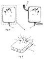
- Fig.5
- eine perspektivische Darstellung der Einzelheit V nach Fig. 4,
- Fig.6
- eine Draufsicht auf die Darstellung nach Fig. 5,
- Fig.7
- eine perspektivische Darstellung der Einzelheit V nach Fig. 4 in alternativer Ausgestaltung.
- Fig.1
- an exploded view of a switch of the device according to the invention,
- Fig.2
- a perspective view of the switch of FIG. 1,
- Figure 3
- a side view of the switch of FIG. 1,
- Figure 4
- two mirror-symmetrical housings of the device,
- Figure 5
- a perspective view of the detail V of FIG. 4,
- Figure 6
- a top view of the illustration of FIG. 5,
- Figure 7
- a perspective view of the detail V of FIG. 4 in an alternative embodiment.
Der Schalter 1 besteht im Wesentlichen aus einem metallischen, mit einer endseitigen Spitze 11 versehenen Stift 2, der innerhalb eines Elektromagneten 3 angeordnet ist, wobei der Elektromagnet 3 derart ansteuerbar ist, dass der Stift 2 in seiner axialen Richtung von einer eingezogenen in eine ausgezogene Position verlagerbar ist. In dieser ausgezogenen Positionen steht der Stift 2 senkrecht nach oben über den Schalter 1 über und reizt mit seiner Spitze 11 die Haut einer auf dem Schalter 1 aufliegenden Fingerspitze einer zu untersuchenden Person.The
Des Weiteren ist dem Schalter 1 ein Druckaufnehmer zugeordnet, der hier in Form einer ringförmigen Tastplatte 4 mit einer mittigen Ausnehmung für den Stift 2 ausgebildet ist. Wird der Druckaufnehmer bzw. die Tastplatte 4 betätigt, wird die Tastplatte 4 gemeinsam mit dem Stift 2 und dem Elektromagneten 3 in axialer Richtung, wie durch den Doppelpfeil A angedeutet, nach unten verlagert. Hierfür ist der Elektromagnet 3 in einer hier zweiteilig ausgebildeten Führung 5 verschiebbar angeordnet. Die Tastplatte 4 kann unabhängig von der Stellung des Stifts 2 betätigt werden.Furthermore, the
Unterhalb des Elektromagneten 3 weist der Schalter 1 einen Beschleunigungsblock 6 auf, um die Bewegung des Elektromagneten 3 bzw. der Tastplatte 4 auf einen in einer Halterung 7 angeordneten Mikroschalter 8 zu übertragen. Mit dem Beschleunigungsblock 6 kann eine Bewegung des Elektromagneten 3 und der Tastplatte 4 gedämpft werden. Des Weiteren ermöglicht der Beschleunigungsblock 6 in Abhängigkeit von seiner Ausgestaltung eine Variation der Endgeschwindigkeit des Stiftes 2 und damit des ausgelösten Impulses. Zusätzlich weist der Mikroschalter 8 eine Feder auf, um nach dem Loslassen der Tastplatte 4 diese sowie den Elektromagneten 3 wieder nach oben in die ursprüngliche Position zurückzuverlagern. Die Führung 5 und die Halterung 7 bestehen vorzugsweise aus Metall und/oder Kunststoff.Below the
Die Signale des Mikroschalters 8 werden über eine geeignete Steuerung, die hard- und/oder softwaremäßig implementiert ist, ausgelesen und der Elektromagnet 3 mittels der Steuerung in gewünschter Weise angesteuert, um unterschiedliche neuropsychologische Tests mit der Vorrichtung durchzuführen. Dazulässt sich die Steuerung derart variieren, dass Einzelimpulse, Mehrfachimpuse bis hin zu Dauerimpulsen (Vibration) des Stiftes 2 möglich sind. Der Impuls des Stiftes 2 kann auch durch eine Anpassung der Anschaltdauer bzw. eine Veränderung der Betriebsspannung des Elektromagneten 3 in einem weiten Bereich bis hinab zur Tastschwelle beeinflusst werden.The signals of the
Die Vorrichtung besteht im Wesentlichen aus zwei spiegelsymmetrisch ausgebildeten Gehäusen 9, an deren Oberseiten jeweils mehrere Schalter 1 in ergonomischer Weise verteilt angeordnet sind, um jeweils vier Finger einer Hand zu stimulieren und die Reaktionen hierauf zu erfassen. Prinzipiell kann in den Gehäusen 9 jeweils auch ein fünfter Schalter 1 für den Daumen vorgesehen sein. Aus den als Handauflage dienenden Gehäusen 9 sind Leitungen 10 zur Energieversorgung sowie zur Ansteuerung der Schalter 1 bzw. zum Auslesen der Messdaten herausgeführt, wobei die Auswertung und Ansteuerung vorzugsweise mit einem entsprechenden Programm über einen PC erfolgt.The device consists essentially of two mirror-
Claims (8)
- Apparatus for accomplishing a neuropsychological test with a switch (1), which includes a displaceable pin (2) whereby a stimulus can be exerted upon a finger-tip of a person to be tested, characterised in that a pressure sensor, which is actuatable with the finger-tip and can be acted-upon independently of the position of the pin (2), is associated with the switch (1).
- Apparatus according to claim 1, characterised in that the pressure sensor includes a scanning plate (4), and the pin (2) extends through a recess in the scanning plate (4).
- Apparatus according to claim 1 or 2, characterised in that the pressure, whereby the pressure sensor is actuated, is measurable, more especially via a piezoelectric element.
- Apparatus according to one of claims 1 to 3, characterised in that two housings (9) are provided, each with four or five ergonomically disposed switches (1) having pins (2) and pressure sensors.
- Apparatus according to one of claims 1 to 4, characterised in that the pin (2) is actuatable with an electromagnet (3).
- Apparatus according to claim 5, characterised in that the pressure sensor is displaceable jointly with the electromagnet (3).
- Apparatus according to claim 5 or 6, characterised in that the pressure sensor and the electromagnet (3) are acted-upon by a resilient force.
- Apparatus according to one of claims 1 to 7, characterised in that additional, more especially visual and/or audible, signalling means are provided.
Applications Claiming Priority (1)
| Application Number | Priority Date | Filing Date | Title |
|---|---|---|---|
| DE102004054656A DE102004054656B3 (en) | 2004-11-11 | 2004-11-11 | Device for carrying out a neuropsychological test |
Publications (2)
| Publication Number | Publication Date |
|---|---|
| EP1656885A1 EP1656885A1 (en) | 2006-05-17 |
| EP1656885B1 true EP1656885B1 (en) | 2007-07-04 |
Family
ID=35698247
Family Applications (1)
| Application Number | Title | Priority Date | Filing Date |
|---|---|---|---|
| EP05024511A Not-in-force EP1656885B1 (en) | 2004-11-11 | 2005-11-10 | Device for performing a neuropsychological test |
Country Status (3)
| Country | Link |
|---|---|
| EP (1) | EP1656885B1 (en) |
| AT (1) | ATE366080T1 (en) |
| DE (2) | DE102004054656B3 (en) |
Cited By (1)
| Publication number | Priority date | Publication date | Assignee | Title |
|---|---|---|---|---|
| EP3081151A1 (en) | 2015-04-16 | 2016-10-19 | Finn Gilling Christensen | Device and methods for diagnosing adhd and/or autism |
Families Citing this family (4)
| Publication number | Priority date | Publication date | Assignee | Title |
|---|---|---|---|---|
| CN102316802B (en) | 2009-02-12 | 2014-01-29 | 特拉维夫大学拉玛特有限公司 | Method and system for detecting neuropathy |
| KR101004001B1 (en) * | 2010-05-17 | 2010-12-31 | 박종은 | Testing apparatus for nerve function |
| DE102010022699A1 (en) | 2010-06-04 | 2011-12-08 | Universität Leipzig | Detecting arrangement for use in e.g. neuropsychological testing places for haptic detectability of object structures during closing of eyes of patient, has frame comprising upper and lower frames, where lower frame comprises base plate |
| CN110037745A (en) * | 2019-05-29 | 2019-07-23 | 宋晶晶 | It is a kind of for testing the Neurology clinic percussion hammer of knee jerk reaction |
Family Cites Families (2)
| Publication number | Priority date | Publication date | Assignee | Title |
|---|---|---|---|---|
| US4516939A (en) * | 1979-05-24 | 1985-05-14 | Quill Licensing | Finger control system |
| US5002065A (en) * | 1988-04-20 | 1991-03-26 | Link Performance And Recovery Systems | Vibratory screening or diagnostic systems |
-
2004
- 2004-11-11 DE DE102004054656A patent/DE102004054656B3/en not_active Expired - Fee Related
-
2005
- 2005-11-10 EP EP05024511A patent/EP1656885B1/en not_active Not-in-force
- 2005-11-10 DE DE502005000970T patent/DE502005000970D1/en not_active Expired - Fee Related
- 2005-11-10 AT AT05024511T patent/ATE366080T1/en not_active IP Right Cessation
Non-Patent Citations (1)
| Title |
|---|
| None * |
Cited By (1)
| Publication number | Priority date | Publication date | Assignee | Title |
|---|---|---|---|---|
| EP3081151A1 (en) | 2015-04-16 | 2016-10-19 | Finn Gilling Christensen | Device and methods for diagnosing adhd and/or autism |
Also Published As
| Publication number | Publication date |
|---|---|
| EP1656885A1 (en) | 2006-05-17 |
| DE502005000970D1 (en) | 2007-08-16 |
| ATE366080T1 (en) | 2007-07-15 |
| DE102004054656B3 (en) | 2006-07-13 |
Similar Documents
| Publication | Publication Date | Title |
|---|---|---|
| EP2761399B1 (en) | Dataglove having tactile feedback and method | |
| EP2016480B1 (en) | Optoelectronic device for the detection of the position and/or movement of an object, and associated method | |
| EP3043240A1 (en) | Operating device with improved haptic feedback | |
| Pruett Jr et al. | Response patterns in second somatosensory cortex (SII) of awake monkeys to passively applied tactile gratings | |
| EP2972698B1 (en) | Method for operating a touch-sensitive control system and device having such a control system | |
| WO2016189017A1 (en) | Operating device with fast haptic feedback | |
| DE10240642A1 (en) | Pressure sensitive functionality for keys on a keyboard | |
| WO2010097308A1 (en) | Input device and method for providing an output signal associated with a sensor field assignment | |
| DE102015209593A1 (en) | Operating device with fast haptic feedback | |
| DE102008002544A1 (en) | Method and device for identifying a person by means of their typing behavior, taking into account the local distribution of the keys of a keyboard | |
| EP1656885B1 (en) | Device for performing a neuropsychological test | |
| EP1142118A1 (en) | Tactile sensor | |
| DE19948620A1 (en) | Dental facility | |
| DE102009006448A1 (en) | Passenger sitting position determining method for e.g. passenger car, involves determining sitting position of occupant approximated to control element in vehicle in dependence upon approximation information | |
| DE102013007008B4 (en) | Operating device for a motor vehicle | |
| EP1895392A1 (en) | Device for operating the functions of a device | |
| WO2015113759A1 (en) | Operating aid for a touch-sensitive display | |
| DE102007004250A1 (en) | Haptic control element for use in a motor vehicle generates control signals for controlling a motor vehicle's device | |
| DE4237844C1 (en) | Computer keyboard with integrated cursor control units - has cursors in form of linear belt elements along two adjacent sides operated by fingers and with pulse generating switches | |
| DE102013006174A1 (en) | Method for operating a control system of a motor vehicle and operating system for a motor vehicle | |
| EP3496124B1 (en) | Method for controlling an operating device for a motor vehicle and operating device | |
| DE102018126472A1 (en) | Input device for a motor vehicle and method for controlling the input device | |
| EP2336742A1 (en) | Method and system for recording a sensor surface being contacted by an object | |
| DE102004046526B4 (en) | Tactile control device | |
| DE202023105636U1 (en) | Input device, measuring system and computer program |
Legal Events
| Date | Code | Title | Description |
|---|---|---|---|
| PUAI | Public reference made under article 153(3) epc to a published international application that has entered the european phase |
Free format text: ORIGINAL CODE: 0009012 |
|
| AK | Designated contracting states |
Kind code of ref document: A1 Designated state(s): AT BE BG CH CY CZ DE DK EE ES FI FR GB GR HU IE IS IT LI LT LU LV MC NL PL PT RO SE SI SK TR |
|
| AX | Request for extension of the european patent |
Extension state: AL BA HR MK YU |
|
| 17P | Request for examination filed |
Effective date: 20061026 |
|
| GRAP | Despatch of communication of intention to grant a patent |
Free format text: ORIGINAL CODE: EPIDOSNIGR1 |
|
| AKX | Designation fees paid |
Designated state(s): AT BE BG CH CY CZ DE DK EE ES FI FR GB GR HU IE IS IT LI LT LU LV MC NL PL PT RO SE SI SK TR |
|
| GRAS | Grant fee paid |
Free format text: ORIGINAL CODE: EPIDOSNIGR3 |
|
| GRAA | (expected) grant |
Free format text: ORIGINAL CODE: 0009210 |
|
| AK | Designated contracting states |
Kind code of ref document: B1 Designated state(s): AT BE BG CH CY CZ DE DK EE ES FI FR GB GR HU IE IS IT LI LT LU LV MC NL PL PT RO SE SI SK TR |
|
| REG | Reference to a national code |
Ref country code: GB Ref legal event code: FG4D Free format text: NOT ENGLISH |
|
| REG | Reference to a national code |
Ref country code: CH Ref legal event code: EP |
|
| REG | Reference to a national code |
Ref country code: IE Ref legal event code: FG4D Free format text: LANGUAGE OF EP DOCUMENT: GERMAN |
|
| REF | Corresponds to: |
Ref document number: 502005000970 Country of ref document: DE Date of ref document: 20070816 Kind code of ref document: P |
|
| REG | Reference to a national code |
Ref country code: CH Ref legal event code: NV Representative=s name: PA ALDO ROEMPLER |
|
| NLV1 | Nl: lapsed or annulled due to failure to fulfill the requirements of art. 29p and 29m of the patents act | ||
| GBV | Gb: ep patent (uk) treated as always having been void in accordance with gb section 77(7)/1977 [no translation filed] |
Effective date: 20070704 |
|
| PG25 | Lapsed in a contracting state [announced via postgrant information from national office to epo] |
Ref country code: BG Free format text: LAPSE BECAUSE OF FAILURE TO SUBMIT A TRANSLATION OF THE DESCRIPTION OR TO PAY THE FEE WITHIN THE PRESCRIBED TIME-LIMIT Effective date: 20071004 Ref country code: SI Free format text: LAPSE BECAUSE OF FAILURE TO SUBMIT A TRANSLATION OF THE DESCRIPTION OR TO PAY THE FEE WITHIN THE PRESCRIBED TIME-LIMIT Effective date: 20070704 Ref country code: FI Free format text: LAPSE BECAUSE OF FAILURE TO SUBMIT A TRANSLATION OF THE DESCRIPTION OR TO PAY THE FEE WITHIN THE PRESCRIBED TIME-LIMIT Effective date: 20070704 Ref country code: PT Free format text: LAPSE BECAUSE OF FAILURE TO SUBMIT A TRANSLATION OF THE DESCRIPTION OR TO PAY THE FEE WITHIN THE PRESCRIBED TIME-LIMIT Effective date: 20071204 Ref country code: IS Free format text: LAPSE BECAUSE OF FAILURE TO SUBMIT A TRANSLATION OF THE DESCRIPTION OR TO PAY THE FEE WITHIN THE PRESCRIBED TIME-LIMIT Effective date: 20071104 Ref country code: NL Free format text: LAPSE BECAUSE OF FAILURE TO SUBMIT A TRANSLATION OF THE DESCRIPTION OR TO PAY THE FEE WITHIN THE PRESCRIBED TIME-LIMIT Effective date: 20070704 Ref country code: LT Free format text: LAPSE BECAUSE OF FAILURE TO SUBMIT A TRANSLATION OF THE DESCRIPTION OR TO PAY THE FEE WITHIN THE PRESCRIBED TIME-LIMIT Effective date: 20070704 Ref country code: ES Free format text: LAPSE BECAUSE OF FAILURE TO SUBMIT A TRANSLATION OF THE DESCRIPTION OR TO PAY THE FEE WITHIN THE PRESCRIBED TIME-LIMIT Effective date: 20071015 |
|
| EN | Fr: translation not filed | ||
| PG25 | Lapsed in a contracting state [announced via postgrant information from national office to epo] |
Ref country code: PL Free format text: LAPSE BECAUSE OF FAILURE TO SUBMIT A TRANSLATION OF THE DESCRIPTION OR TO PAY THE FEE WITHIN THE PRESCRIBED TIME-LIMIT Effective date: 20070704 |
|
| PGFP | Annual fee paid to national office [announced via postgrant information from national office to epo] |
Ref country code: AT Payment date: 20071128 Year of fee payment: 3 |
|
| REG | Reference to a national code |
Ref country code: IE Ref legal event code: FD4D |
|
| PG25 | Lapsed in a contracting state [announced via postgrant information from national office to epo] |
Ref country code: LV Free format text: LAPSE BECAUSE OF FAILURE TO SUBMIT A TRANSLATION OF THE DESCRIPTION OR TO PAY THE FEE WITHIN THE PRESCRIBED TIME-LIMIT Effective date: 20070704 |
|
| PG25 | Lapsed in a contracting state [announced via postgrant information from national office to epo] |
Ref country code: GR Free format text: LAPSE BECAUSE OF FAILURE TO SUBMIT A TRANSLATION OF THE DESCRIPTION OR TO PAY THE FEE WITHIN THE PRESCRIBED TIME-LIMIT Effective date: 20071005 Ref country code: DK Free format text: LAPSE BECAUSE OF FAILURE TO SUBMIT A TRANSLATION OF THE DESCRIPTION OR TO PAY THE FEE WITHIN THE PRESCRIBED TIME-LIMIT Effective date: 20070704 |
|
| PLBE | No opposition filed within time limit |
Free format text: ORIGINAL CODE: 0009261 |
|
| STAA | Information on the status of an ep patent application or granted ep patent |
Free format text: STATUS: NO OPPOSITION FILED WITHIN TIME LIMIT |
|
| PG25 | Lapsed in a contracting state [announced via postgrant information from national office to epo] |
Ref country code: IE Free format text: LAPSE BECAUSE OF FAILURE TO SUBMIT A TRANSLATION OF THE DESCRIPTION OR TO PAY THE FEE WITHIN THE PRESCRIBED TIME-LIMIT Effective date: 20070704 Ref country code: SK Free format text: LAPSE BECAUSE OF FAILURE TO SUBMIT A TRANSLATION OF THE DESCRIPTION OR TO PAY THE FEE WITHIN THE PRESCRIBED TIME-LIMIT Effective date: 20070704 Ref country code: GB Free format text: LAPSE BECAUSE OF FAILURE TO SUBMIT A TRANSLATION OF THE DESCRIPTION OR TO PAY THE FEE WITHIN THE PRESCRIBED TIME-LIMIT Effective date: 20070704 Ref country code: CZ Free format text: LAPSE BECAUSE OF FAILURE TO SUBMIT A TRANSLATION OF THE DESCRIPTION OR TO PAY THE FEE WITHIN THE PRESCRIBED TIME-LIMIT Effective date: 20070704 |
|
| PGFP | Annual fee paid to national office [announced via postgrant information from national office to epo] |
Ref country code: DE Payment date: 20080110 Year of fee payment: 3 |
|
| BERE | Be: lapsed |
Owner name: WITTLING, WERNER, DR. Effective date: 20071130 Owner name: WITTLING, RALF ARNE Effective date: 20071130 |
|
| 26N | No opposition filed |
Effective date: 20080407 |
|
| PG25 | Lapsed in a contracting state [announced via postgrant information from national office to epo] |
Ref country code: SE Free format text: LAPSE BECAUSE OF FAILURE TO SUBMIT A TRANSLATION OF THE DESCRIPTION OR TO PAY THE FEE WITHIN THE PRESCRIBED TIME-LIMIT Effective date: 20071004 Ref country code: MC Free format text: LAPSE BECAUSE OF NON-PAYMENT OF DUE FEES Effective date: 20071130 Ref country code: RO Free format text: LAPSE BECAUSE OF FAILURE TO SUBMIT A TRANSLATION OF THE DESCRIPTION OR TO PAY THE FEE WITHIN THE PRESCRIBED TIME-LIMIT Effective date: 20070704 |
|
| PG25 | Lapsed in a contracting state [announced via postgrant information from national office to epo] |
Ref country code: FR Free format text: LAPSE BECAUSE OF FAILURE TO SUBMIT A TRANSLATION OF THE DESCRIPTION OR TO PAY THE FEE WITHIN THE PRESCRIBED TIME-LIMIT Effective date: 20080229 |
|
| REG | Reference to a national code |
Ref country code: CH Ref legal event code: PCAR Free format text: ALDO ROEMPLER PATENTANWALT;BRENDENWEG 11 POSTFACH 154;9424 RHEINECK (CH) |
|
| PG25 | Lapsed in a contracting state [announced via postgrant information from national office to epo] |
Ref country code: BE Free format text: LAPSE BECAUSE OF NON-PAYMENT OF DUE FEES Effective date: 20071130 |
|
| PG25 | Lapsed in a contracting state [announced via postgrant information from national office to epo] |
Ref country code: EE Free format text: LAPSE BECAUSE OF FAILURE TO SUBMIT A TRANSLATION OF THE DESCRIPTION OR TO PAY THE FEE WITHIN THE PRESCRIBED TIME-LIMIT Effective date: 20070704 |
|
| PG25 | Lapsed in a contracting state [announced via postgrant information from national office to epo] |
Ref country code: CY Free format text: LAPSE BECAUSE OF FAILURE TO SUBMIT A TRANSLATION OF THE DESCRIPTION OR TO PAY THE FEE WITHIN THE PRESCRIBED TIME-LIMIT Effective date: 20070704 |
|
| PG25 | Lapsed in a contracting state [announced via postgrant information from national office to epo] |
Ref country code: LU Free format text: LAPSE BECAUSE OF NON-PAYMENT OF DUE FEES Effective date: 20071110 Ref country code: AT Free format text: LAPSE BECAUSE OF NON-PAYMENT OF DUE FEES Effective date: 20081110 |
|
| PG25 | Lapsed in a contracting state [announced via postgrant information from national office to epo] |
Ref country code: TR Free format text: LAPSE BECAUSE OF FAILURE TO SUBMIT A TRANSLATION OF THE DESCRIPTION OR TO PAY THE FEE WITHIN THE PRESCRIBED TIME-LIMIT Effective date: 20070704 Ref country code: HU Free format text: LAPSE BECAUSE OF FAILURE TO SUBMIT A TRANSLATION OF THE DESCRIPTION OR TO PAY THE FEE WITHIN THE PRESCRIBED TIME-LIMIT Effective date: 20080105 |
|
| PG25 | Lapsed in a contracting state [announced via postgrant information from national office to epo] |
Ref country code: DE Free format text: LAPSE BECAUSE OF NON-PAYMENT OF DUE FEES Effective date: 20090603 |
|
| REG | Reference to a national code |
Ref country code: CH Ref legal event code: PL |
|
| PG25 | Lapsed in a contracting state [announced via postgrant information from national office to epo] |
Ref country code: CH Free format text: LAPSE BECAUSE OF NON-PAYMENT OF DUE FEES Effective date: 20091130 Ref country code: LI Free format text: LAPSE BECAUSE OF NON-PAYMENT OF DUE FEES Effective date: 20091130 |
|
| PG25 | Lapsed in a contracting state [announced via postgrant information from national office to epo] |
Ref country code: IT Free format text: LAPSE BECAUSE OF NON-PAYMENT OF DUE FEES Effective date: 20071130 |