EP1655516A2 - Shift operation device - Google Patents
Shift operation device Download PDFInfo
- Publication number
- EP1655516A2 EP1655516A2 EP05023755A EP05023755A EP1655516A2 EP 1655516 A2 EP1655516 A2 EP 1655516A2 EP 05023755 A EP05023755 A EP 05023755A EP 05023755 A EP05023755 A EP 05023755A EP 1655516 A2 EP1655516 A2 EP 1655516A2
- Authority
- EP
- European Patent Office
- Prior art keywords
- unit
- state
- shift
- pushed
- shift knob
- Prior art date
- Legal status (The legal status is an assumption and is not a legal conclusion. Google has not performed a legal analysis and makes no representation as to the accuracy of the status listed.)
- Granted
Links
Images





Classifications
-
- G—PHYSICS
- G05—CONTROLLING; REGULATING
- G05G—CONTROL DEVICES OR SYSTEMS INSOFAR AS CHARACTERISED BY MECHANICAL FEATURES ONLY
- G05G1/00—Controlling members, e.g. knobs or handles; Assemblies or arrangements thereof; Indicating position of controlling members
- G05G1/08—Controlling members for hand actuation by rotary movement, e.g. hand wheels
- G05G1/087—Controlling members for hand actuation by rotary movement, e.g. hand wheels retractable; Flush control knobs
-
- B—PERFORMING OPERATIONS; TRANSPORTING
- B60—VEHICLES IN GENERAL
- B60K—ARRANGEMENT OR MOUNTING OF PROPULSION UNITS OR OF TRANSMISSIONS IN VEHICLES; ARRANGEMENT OR MOUNTING OF PLURAL DIVERSE PRIME-MOVERS IN VEHICLES; AUXILIARY DRIVES FOR VEHICLES; INSTRUMENTATION OR DASHBOARDS FOR VEHICLES; ARRANGEMENTS IN CONNECTION WITH COOLING, AIR INTAKE, GAS EXHAUST OR FUEL SUPPLY OF PROPULSION UNITS IN VEHICLES
- B60K35/00—Instruments specially adapted for vehicles; Arrangement of instruments in or on vehicles
- B60K35/10—Input arrangements, i.e. from user to vehicle, associated with vehicle functions or specially adapted therefor
-
- F—MECHANICAL ENGINEERING; LIGHTING; HEATING; WEAPONS; BLASTING
- F16—ENGINEERING ELEMENTS AND UNITS; GENERAL MEASURES FOR PRODUCING AND MAINTAINING EFFECTIVE FUNCTIONING OF MACHINES OR INSTALLATIONS; THERMAL INSULATION IN GENERAL
- F16H—GEARING
- F16H59/00—Control inputs to control units of change-speed- or reversing-gearings for conveying rotary motion
- F16H59/02—Selector apparatus
- F16H59/08—Range selector apparatus
-
- G—PHYSICS
- G05—CONTROLLING; REGULATING
- G05G—CONTROL DEVICES OR SYSTEMS INSOFAR AS CHARACTERISED BY MECHANICAL FEATURES ONLY
- G05G5/00—Means for preventing, limiting or returning the movements of parts of a control mechanism, e.g. locking controlling member
- G05G5/06—Means for preventing, limiting or returning the movements of parts of a control mechanism, e.g. locking controlling member for holding members in one or a limited number of definite positions only
-
- B—PERFORMING OPERATIONS; TRANSPORTING
- B60—VEHICLES IN GENERAL
- B60K—ARRANGEMENT OR MOUNTING OF PROPULSION UNITS OR OF TRANSMISSIONS IN VEHICLES; ARRANGEMENT OR MOUNTING OF PLURAL DIVERSE PRIME-MOVERS IN VEHICLES; AUXILIARY DRIVES FOR VEHICLES; INSTRUMENTATION OR DASHBOARDS FOR VEHICLES; ARRANGEMENTS IN CONNECTION WITH COOLING, AIR INTAKE, GAS EXHAUST OR FUEL SUPPLY OF PROPULSION UNITS IN VEHICLES
- B60K2360/00—Indexing scheme associated with groups B60K35/00 or B60K37/00 relating to details of instruments or dashboards
- B60K2360/126—Rotatable input devices for instruments
-
- F—MECHANICAL ENGINEERING; LIGHTING; HEATING; WEAPONS; BLASTING
- F16—ENGINEERING ELEMENTS AND UNITS; GENERAL MEASURES FOR PRODUCING AND MAINTAINING EFFECTIVE FUNCTIONING OF MACHINES OR INSTALLATIONS; THERMAL INSULATION IN GENERAL
- F16H—GEARING
- F16H59/00—Control inputs to control units of change-speed- or reversing-gearings for conveying rotary motion
- F16H59/02—Selector apparatus
- F16H59/08—Range selector apparatus
- F16H2059/081—Range selector apparatus using knops or discs for rotary range selection
-
- F—MECHANICAL ENGINEERING; LIGHTING; HEATING; WEAPONS; BLASTING
- F16—ENGINEERING ELEMENTS AND UNITS; GENERAL MEASURES FOR PRODUCING AND MAINTAINING EFFECTIVE FUNCTIONING OF MACHINES OR INSTALLATIONS; THERMAL INSULATION IN GENERAL
- F16H—GEARING
- F16H59/00—Control inputs to control units of change-speed- or reversing-gearings for conveying rotary motion
- F16H59/50—Inputs being a function of the status of the machine, e.g. position of doors or safety belts
- F16H59/54—Inputs being a function of the status of the machine, e.g. position of doors or safety belts dependent on signals from the brakes, e.g. parking brakes
-
- F—MECHANICAL ENGINEERING; LIGHTING; HEATING; WEAPONS; BLASTING
- F16—ENGINEERING ELEMENTS AND UNITS; GENERAL MEASURES FOR PRODUCING AND MAINTAINING EFFECTIVE FUNCTIONING OF MACHINES OR INSTALLATIONS; THERMAL INSULATION IN GENERAL
- F16H—GEARING
- F16H61/00—Control functions within control units of change-speed- or reversing-gearings for conveying rotary motion ; Control of exclusively fluid gearing, friction gearing, gearings with endless flexible members or other particular types of gearing
- F16H61/22—Locking of the control input devices
-
- H—ELECTRICITY
- H01—ELECTRIC ELEMENTS
- H01H—ELECTRIC SWITCHES; RELAYS; SELECTORS; EMERGENCY PROTECTIVE DEVICES
- H01H3/00—Mechanisms for operating contacts
- H01H3/02—Operating parts, i.e. for operating driving mechanism by a mechanical force external to the switch
- H01H2003/0293—Operating parts, i.e. for operating driving mechanism by a mechanical force external to the switch with an integrated touch switch
-
- H—ELECTRICITY
- H01—ELECTRIC ELEMENTS
- H01H—ELECTRIC SWITCHES; RELAYS; SELECTORS; EMERGENCY PROTECTIVE DEVICES
- H01H3/00—Mechanisms for operating contacts
- H01H3/02—Operating parts, i.e. for operating driving mechanism by a mechanical force external to the switch
- H01H3/08—Turn knobs
- H01H2003/085—Retractable turn knobs, e.g. flush mounted
-
- H—ELECTRICITY
- H01—ELECTRIC ELEMENTS
- H01H—ELECTRIC SWITCHES; RELAYS; SELECTORS; EMERGENCY PROTECTIVE DEVICES
- H01H9/00—Details of switching devices, not covered by groups H01H1/00 - H01H7/00
- H01H9/20—Interlocking, locking, or latching mechanisms
- H01H9/22—Interlocking, locking, or latching mechanisms for interlocking between casing, cover, or protective shutter and mechanism for operating contacts
- H01H9/223—Defeatable locking means
Definitions
- the present invention relates to a shift operation device for electronically switching an automatic transmission from a parking state to a shift state.
- an example of a shift operation device includes an operation unit (shift dial) which can be rotated and pushed, a detecting unit for detecting a pushed state and a non-pushed state of the operation unit and detecting switching signals for setting and releasing of parking in the respective states, a rotation detecting unit for detecting rotation state of the operation unit and outputting a select signal of the shift state, and a pop-up unit for switching the operation unit from the pushed state to the non-pushed state.
- the pop-up unit switches the operation unit from the pushed state to the non-pushed state when a brake is operated (for example, see JP-A-2001-277892 (2-6 pages, Fig. 1)).
- the pop-up unit has a coil spring for pushing back the operation unit in a non-pushed state direction and an electro-magnetic solenoid for locking the operation unit in the pushed state against the pushing back force of the coil spring.
- the parking state can not be released by only manually operating the operation unit, and the operation unit of the parking state does not pop-up to the shift selectable state as long as the brake is not operated.
- the driver releases the parking, if the foot of the driver accidentally contacts the brake such that the brake operates, since the parking state is released just before the brake is operated by the driver, an actual pop-up timing of the operation unit is different from the operating feeling of the driver. Therefore, the driver feels a sense of incongruity.
- the invention has been finalized in view of the drawbacks inherent in the related art, and it is an object of the invention to provide a shift operation device which can surely prevent a parking state from being released against the will of a driver.
- a shift operation device includes: an operation unit which can be rotated and pushed; a push detecting unit which detects a pushed state and a non-pushed state of the operation unit and outputs switching signals for setting and releasing parking in the respective states; a rotation detecting unit which detects a rotation state of the operation unit and outputs a shift select signal; and a pop-up unit which switches the operation unit from the pushed state to the non-pushed state.
- the pop-up unit switches the operation unit from the pushed state to the non-pushed state.
- the parking state of the operation unit can be released. Accordingly, even if the brake is accidentally operated by the driver, the parking state is not released, and thus the parking state can be surely prevented from being released without the driver's intend.
- the pop-up unit may include a press operation detecting unit which detects press operation of the operation unit and an actuator which lifts up the operation unit from the pushed state to the non-pushed state, and, when the brake is operated and the press operation detecting unit detects the press operation, the actuator may lift up the operation unit.
- the pop-up unit may include a press operation detecting unit which detects press operation of the operation unit, a spring unit which pushes back the operation unit in the non-pushed state direction, and a lock unit which locks the operation unit against the pushing back force of the spring unit, and, when the brake is operated and the press operation detecting unit detects the press operation, the lock unit may release the locked state of the operation unit.
- the pop-up unit may include a push lock unit which alternately performs returning control of the operation unit to the non-pushed state and returning control release whenever the operation unit is pressed, a spring unit which pushes back the operation unit in the non-pushed state direction, and a lock unit which locks the operation unit to the pushed state against the pushing back force of the spring unit, and, when the brake is operated, the lock unit may release the locked state of the operation unit.
- the push lock unit may be composed of a heart cam tool and so on, and the heart cam tool may include a sliding member which moves together with the operation unit and a cam groove which movably guides the sliding member in lock and lock releasing directions.
- the lock unit may include an electro-magnetic actuator having a movable rod which can move in an engaging and disengaging direction of the operation unit.
- the parking state of the operation unit can be released. Accordingly, even if the brake is accidentally operated by the driver, the parking state is not released, and thus the parking state can be surely prevented from being released without the driver's intend.
- Fig. 1 is a cross-sectional view illustrating a parking setting state of a shift operation device according to a first embodiment of the invention
- Fig. 2 is a cross-sectional view illustrating a state when a shift knob included in the shift operation device is pushed
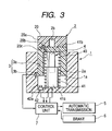
- Fig. 3 is a cross-sectional view illustrating a pop-up state of the shift knob
- Fig. 4 is a flowchart illustrating an operation of the shift operation device.
- the shift operation device electronically switches an automatic transmission of a vehicle between a parking state and a shift state, and, as shown in Figs. 1 through 3, mainly includes a housing 1, a columnar shift knob 2 which can be rotated and pushed, a push detecting switch 3 for detecting a pushed state and a non-pushed state of the shift knob 2, a pop-up tool 4 for popping up the shift knob 2, and a control unit 7 for controlling an automatic transmission 5 based on the rotated and pushed state of the shift knob 2 or controlling the pop-up tool 4 based on a predetermined operation of the shift knob 2 and the operation of a brake 6 included in the vehicle.
- the automatic transmission 5 is set to the parking state in the pushed state of the shift knob 2 and is set to a parking release state, that is, a shift selectable state in the non-pushed state of the shift knob 2.
- a parking release state that is, a shift selectable state in the non-pushed state of the shift knob 2.
- the automatic transmission 5 is shifted and selected to a predetermined mode by the rotation of the shift knob 2.
- a columnar concave portion 1a for opening an upper surface thereof is formed in the housing 1, and the shift knob 2 is vertically movably and rotatably supported in the concave portion 1a.
- a concave portion 2a for opening a lower surface thereof is formed in the shift knob 2, and the shift knob 2 has a rotary switch 20 at an upper end thereof.
- the rotary switch 20 includes a rotation unit 20a which can rotate around a rotation shaft 2b, a plurality of magnets 20b which are arranged around the rotation shaft 2b at a lower surface of the rotation unit 20a and correspond to a predetermined shift mode, and a hall element 20c for detecting magnetism of each magnet 20b.
- the magnetism of a predetermined magnet 20b is detected by the hall element 20c when the rotation unit 20a rotates, and thus a corresponding shift select signal is output from the hall element 20c to the control unit 7.
- the push detecting switch 3 includes a magnet 3a buried in the outer circumferential surface of the shift knob 2, and a hall element 3b provided in the housing 1 to be exposed in the inner circumferential surface of the concave portion 1a.
- the magnet 3a faces the hall element 3b and the magnetism of the magnet 3a is detected by the hall element 3b such that the push detecting switch 3 is in an ON state.
- this information is output from the hall element 3b to the control unit 7 as a switching signal to the parking setting.
- the magnet 3a is separated from the hall element 3b, the magnetic loss of the magnet 3a is detected by the hall element 3b and thus the push detecting switch 3 is turned off. This information is output from the hall element 3b to the control unit 7 as a switching signal to the parking releasing.
- the pop-up tool 4 includes a tension spring 40 provided between the shift knob 2 and the housing 1, an actuator 41 provided in the housing 1 to be received in the concave portion 2a of the shift knob 2, and a push switch 42 buried in the inner bottom surface of the concave portion 1a to be opposite to the lower surface of the shift knob 2. Both ends of the tension spring 40 are retained to the upper surface of the concave portion 2a of the shift knob 2 and the inner bottom surface of the concave portion 1a of the housing 1, respectively, and the tension spring 40 always pushes back the shift knob 2 downwardly. At this time, the lower end surface of the shift knob 2 faces an upper surface of the push switch 42.
- the push switch 42 has an operation unit 42a which is pushed back upwardly by a spring (not shown) and the pushing back force of this spring is set to be larger than pushing back force of the tension spring 40. Accordingly, in the state that the shift knob 2 is not operated, the shift knob 2 does not turn on the operation unit 42a and the push switch 42 is in the OFF state.
- the actuator 41 is composed of a linear motor and so on, and has a main body 41a and a movable rod 41b which is supported to the main body 41a so as to be vertically movable.
- a driving voltage is applied from the control unit 7 to the actuator 41, the movable rod 41b rises by an electro-magnetic force and the upper surface of the concave portion 2a is pushed by the front end of the rising movable rod 41b such that the shift knob 2 is popped up against the pushing back force of the tension spring 40.
- the state shown in Fig. 1 is the pushed state of the shift knob 2.
- the push detecting switch 3 is turned on such that the switching signal to the parking setting state is output from the hall element 3b to the control unit 7.
- the automatic transmission 5 is controlled by the control unit 7 to be set to the parking state.
- the driving voltage is not applied from the control unit 7 to the actuator 41, and the lifting-up force is not applied to the shift knob 2 by the movable rod 41b.
- only the pushing back force due to the tension spring 40 is applied to the shift knob 2 and thus the push switch 42 is in the OFF state.
- an ignition switch (not shown) is turned on by the driver such that an engine starts up (YES in step S1 of Fig. 4) and then the brake 6 is operated.
- the shift knob 2 when the shift knob 2 is pressed, if an ON signal from a brake switch (not shown) which is operated by operating the brake 6 and an ON signal from the push switch 42 which is operated by the shift knob 2 are simultaneously detected by the control unit 7 (YES in steps S2 and S3 of Fig. 4), the driving voltage is applied from the control unit 7 to the actuator 41 to drive the movable rod 41b (step S4 of Fig. 4). Accordingly, as shown in Fig.
- the shift knob 2 is popped up upwardly by the lifting-up force of the movable rod 41b (step S5 of Fig. 4).
- a switching signal for releasing the parking state is output from the hall element 3b to the control unit 7 and, based on this switching signal, the automatic transmission 5 is switched from the parking state to the parking release state, that is, the shift selectable state by the control unit 7 (step S7 of Fig. 4).
- the shift mode is set to a neutral state and shift from the neutral state to a predetermined drive mode or the reverse mode can be selected by operating the rotation unit 20a.
- the brake 6 is operated by the driver and the parking switch (not shown) is operated in the state in which the vehicle stops. If the switch is in the ON state, the driving voltage supplied from the control unit 7 to the actuator 41 stops. Thus, since the lifting-up force to the movable rod 41b is released, the shift knob 2 is returned to the pushed state of Fig. 1 by the pushing back force of the tension spring 40. At this time, when the magnet 3a moves to a location facing the hall element 3b and the push detecting switch 3 is turned on, the switching signal to the parking state is output from the hall element 3b to the control unit 7 and thus the parking state is set.
- the parking state of the shift knob 2 can be released. Accordingly, even if the brake 6 is accidentally operated by the driver, the parking state is not released and thus the parking state can be surely prevented from being released without the driver's intend. Moreover, when the shift knob 2 is in the pushed state, since the driving voltage is not applied to the actuator 41, power consumption in the parking state can be reduced.
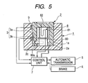
- Fig. 5 is a cross-sectional view illustrating a parking setting state of a shift operation device according to a second embodiment of the invention
- Fig. 6 is a cross-sectional view illustrating a state when a shift knob 2 included in the shift operation device is pressed
- Fig. 7 is a cross-sectional view illustrating a pop-up state of the shift knob 2
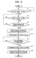
- Fig. 8 is a flowchart illustrating an operation of the shift operation device.
- elements similar to those of the first embodiment are denoted by the same reference numerals and thus their description will be omitted.
- the present embodiment uses a pop-up tool to which the pop-up tool 4 in the first embodiment is modified.
- a pop-up tool 8 includes an electro-magnetic solenoid 80 provided in a housing 1 to be received in a concave portion 2a of a shift knob 2, a coil spring 81 which is provided between the shift knob 2 and the electro-magnetic solenoid 80 and of which both ends are fixed to an upper surface of the electro-magnetic solenoid 80 and an upper surface of the concave portion 2a of the shift knob 2, and a capacitive-type pressure-sensitive sensor 82 provided on an upper surface of the shift knob 2.
- the shift knob 2 of the present embodiment does not have a rotary switch 20 as used in the first embodiment, and the shift is selected by rotating the whole popped-up shift knob 2.
- a hall element 9 is provided at an inner wall surface of the concave portion 1a facing the magnet 3a which moves upwardly by pop-up.
- a plurality of magnets 3a are disposed in an outer circumferential direction of the shift knob 2 in correspondence with a predetermined shift mode.
- the electro-magnetic solenoid 80 has a movable rod 80a which moves horizontally, and an engaging hole 2c to and from which a front end of the movable rod 80a is engaged and disengaged is formed in an inner circumferential surface of the concave portion 2a of the shift knob 2.
- the movable rod 80a is always pushed back in a direction which it is engaged to the engaging hole 2c by a spring member (not shown) and, when the electro-magnetic solenoid 80 is driven by a driving voltage from the control unit 7, the movable rod 80a is driven against the pushing back force of the spring member by a generated electronic force to be separated from the engaging hole 2c. Further, when the driving signal from the control unit 7 stops, the movable rod 80a is engaged to the engaging hole 2c by the pushing back force of the spring member. Also, the coil spring 81 is a spring member for pushing back the shift knob 2 upwardly.
- the state shown in Fig. 5 is a state in which the driving voltage is not applied from the control unit 7 to the electro-magnetic solenoid 80, and, at this time, the front end of the movable rod 80a is engaged to the engaging hole 2c of the shift knob 2 and thus the shift knob 2 is locked in the pushed state against the pushing back force of the coil spring 81.
- a push detecting switch 3 is turned to the ON state such that a switching signal to the parking setting state is output from the hall element 3b to the control unit 7. Further, based on the switching signal, the automatic transmission 5 is controlled by the control unit 7 to be set to the parking state.
- an ignition switch (not shown) is turned on by the driver such that an engine starts up (YES in a step S8 of Fig. 8) and then the brake 6 is operated.
- the pressure-sensitive sensor 82 on the upper surface of the shift knob 2 is pressed, if an ON signal from a brake switch and an ON signal from the pressure-sensitive sensor 82 are simultaneously detected by the control unit 7 (YES in steps S9 and S10 of Fig. 8), the driving voltage is applied from the control unit 7 to the electro-magnetic solenoid 80 (step S11 of Fig. 8) and then the movable rod 80a is separated from the engaging hole 2c.
- step S12 of Fig. 8 the lock state of the shift knob 2 is released and the shift knob 2 is popped up upwardly by the pushing back force of the coil spring 81 (step S12 of Fig. 8).
- the magnet 3a of the shift knob 2 is separated to an upper side of the hall element 3b and, when the push detecting switch 3 is turned off (YES in step S13 of Fig. 8), a switching signal for releasing the parking state is output from the hall element 3b to the control unit 7.
- the automatic transmission 5 is switched from the parking state to the shift selectable state by the control unit 7 which receives this switching signal (step S14 of Fig. 8) and the driving voltage supplied to the electro-magnetic solenoid 80 stops (step S15 of Fig.
- an initial pop-up state of the shift knob 2 the shift mode is set to a neutral state and shift from the neutral state to a predetermined drive mode or the reverse mode can be selected by rotating the shift knob 2.
- the brake 6 is operated by the driver and the shift knob 2 is pushed against the pushing back force of the coil spring 81 in the state in which the vehicle stops.
- the ON state of the pressure-sensitive sensor 82 is detected by the control unit 7, the driving voltage is applied from the control unit 7 to the electro-magnetic solenoid 80 and the movable rode 80a is separated from the engaging hole 2c.
- the switching signal to the parking state is output from the hall element 3b to the control unit 7 and, based on the switching signal, supplement of the driving voltage to the electro-magnetic solenoid 80 stops by the control unit 7.
- the movable rod 80a is engaged to the engaging hole 2c of the shift knob 2 and, as shown in Fig. 5, the shift knob 2 is locked in the pushed state and the parking state is set.
- the electro-magnetic solenoid 80 is used as a lock unit for locking the shift knob 2 in the pushed state and thus the lock unit can be realized by a simple structure, thereby capable of realizing the shift operation device with low cost.
- the driving voltage need not be continuously supplied to the electro-magnetic solenoid 80 and thus power consumption can be even reduced more.
- Fig. 9 is a cross-sectional view illustrating a parking setting state of a shift operation device according to a third embodiment of the invention
- Fig. 10 is a cross-sectional view illustrating a state when a brake of an electro-magnetic solenoid included in the shift operation device is operated
- Fig. 11 is a cross-sectional view illustrating a state when a shift knob 2 included in the shift operation device is pressed
- Fig. 12 is a cross-sectional view illustrating a pop-up state of the shift knob 2
- Fig. 13 is a flowchart illustrating an operation of the shift operation device.
- the members having the same functions as the first and second embodiments are denoted by the same reference numerals and thus their description will be described.
- the present embodiment uses a pop-up tool to which the pop-up tool 4 or 8 in the first or second embodiment is modified.
- a rotary switch 20 is provided on the upper end of a shift knob 2 and the shift state is selected by rotating a rotation unit 20a of the rotary switch 20.
- the hall element 9 used in the second embodiment is not provided and only one magnet 3a of the shift knob 2 is provided for detecting the pushed state.
- a pop-up tool 10 according to the present embodiment has a heart cam tool 100 in addition to an electro-magnetic solenoid 80 and a coil spring 81 which are used in the second embodiment. Further, an engaging hole 2c to and from which a movable rod 80a of the electro-magnetic solenoid 80 is engaged and disengaged is formed in the shift knob 2.
- the functions of the electro-magnetic solenoid 80 and the coil spring 81 are similar to those of the second embodiment, and, in the state shown in Fig. 7, the movable rod 80a is engaged to the engaging hole 2c and the shift knob 2 is locked in the pushed state against a pushing back force of the coil spring 81. Further, the movable rod 80a is separated from the engaging hole 2c by a driving voltage from the control unit 7 such that the lock state of the shift knob 2 is released.
- the heart cam tool 100 has a coupling pin 101 of which one end 101a is axially supported by the shift knob 2 to be moved together with the shift knob 2 and the other end 101b is rotatably provided, and a cam groove 102 which is formed in a housing 1 and movably guides the other end 101b of the coupling pin 101 in lock and lock releasing directions.
- the cam groove 102 has a heart cam groove 102a and a guide groove 102e which extends upwardly to the heart cam groove 102a.
- the heart cam groove 102a has a pin engaging unit 102b for engaging the other end 101b of the coupling pin 101, and an inserting path 102c and a discharge path 102d of the other end 101b.
- FIG. 7 shows a state when the other end 101b is engaged to the pin engaging unit 102b, and, in this state, when the shift knob 2 is pushed downwardly such that the other end 101b of the coupling pin 101 moves from the discharge path 102d to the guide groove 102e, the lock of the other end 101b is released and thus the control to the non-pushed state of the shift knob 2 is released (see Fig. 11).
- the shift knob 2 released to the non-pushed state is pushed again, the other end 101b of the coupling pin 101 is locked from the guide groove 102e to the pin engaging unit 102b through the inserting path 102c so as to return the shift knob 2 to the non-pushed state.
- the heart cam tool 100 alternately performs the returning control to the non-pushed state of the shift knob 2 and the returning control release whenever the shift knob 2 is pushed.
- the movable rod 80a is engaged to the engaging hole 2c of the shift knob 2 such that the shift knob 2 is locked in the pushed state against the pushing back force of the coil spring 81.
- the push detecting switch 3 is turned on and thus a switching signal to the parking setting state is output from the hall element 3b to the control unit 7. Further, based on the switching signal, the automatic transmission 5 is set to the parking state by the control unit 7. Also, in this state, a driving voltage from the control unit 7 is not applied to the electro-magnetic solenoid 80.
- the other end 101b of the coupling pin 101 moves from the pin engaging unit 102b of the cam groove 102 to the guide groove 102e through the discharge path 102c such that the lock state of the other end 101b is released and, as shown in Fig. 12, the shift knob 2 is popped up upwardly by the pushing back force of the coil spring 81 (step S20 of Fig. 13).
- the magnet 3a of the shift knob 2 is separated upwardly from the hall element 3b and, when the push detecting switch 3 is turned off (YES in step S21 of Fig. 13), a switching signal for releasing the parking state is output from the hall element 3b to the control unit 7.
- the automatic transmission 5 is switched from the parking state to the shift selectable state by the control unit 7 which receives this switching signal (step S22 of Fig. 13). Also, in an initial pop-up state of the shift knob 2, the shift mode is set to a neutral state and shift from the neutral state to a predetermined drive mode or the reverse mode can be selected by operating the rotation unit 20a.
- the shift knob 2 can not be pushed and the lock state is not released. That is, even though the shift knob 2 is pushed, the shift mode is not switched to the packing releasing state without operating the brake 6.
- the push detecting switch 3 is turned on such that the switching signal to the parking state is output from the hall element 3b to the control unit 7 and, based on the this switching signal, the driving voltage been supplied to the electro-magnetic solenoid 80 stops.
- the movable rod 80a is engaged to the engaging hole 2c of the shift knob 2 and the shift knob 2 is locked in the pushed state of Fig. 7 and the parking state is set.
- the heart cam tool 100 is used as a push lock unit for alternately performing the returning control to the non-pushed state and the returning control release of the shift knob 2 whenever the shift knob 2 is pressed and thus the push lock unit can be realized by a simple structure, thereby capable of realizing the shift operation device with low cost.
- the driving voltage is not applied to the electro-magnetic solenoid 80 in the state that the shift knob 2 is pushed, power consumption of the parking state can be even reduced more.
Landscapes
- Engineering & Computer Science (AREA)
- General Engineering & Computer Science (AREA)
- Mechanical Engineering (AREA)
- Physics & Mathematics (AREA)
- General Physics & Mathematics (AREA)
- Automation & Control Theory (AREA)
- Chemical & Material Sciences (AREA)
- Combustion & Propulsion (AREA)
- Transportation (AREA)
- Arrangement Or Mounting Of Control Devices For Change-Speed Gearing (AREA)
- Control Of Transmission Device (AREA)
Abstract
Description
- The present invention relates to a shift operation device for electronically switching an automatic transmission from a parking state to a shift state.
- Conventionally, an example of a shift operation device includes an operation unit (shift dial) which can be rotated and pushed, a detecting unit for detecting a pushed state and a non-pushed state of the operation unit and detecting switching signals for setting and releasing of parking in the respective states, a rotation detecting unit for detecting rotation state of the operation unit and outputting a select signal of the shift state, and a pop-up unit for switching the operation unit from the pushed state to the non-pushed state. The pop-up unit switches the operation unit from the pushed state to the non-pushed state when a brake is operated (for example, see JP-A-2001-277892 (2-6 pages, Fig. 1)). Here, the pop-up unit has a coil spring for pushing back the operation unit in a non-pushed state direction and an electro-magnetic solenoid for locking the operation unit in the pushed state against the pushing back force of the coil spring.
- In the shift operation device having the above-described structure, when the brake is operated by a driver in the pushed state of the operation unit, that is, in the state of setting the parking, a brake switch is turned on, the electro-magnetic solenoid is operated by the ON signal, and the operation unit which is locked in the pushed state is released. Accordingly, the operation unit is popped up to the non-pushed state and thus the parking state of the operation unit is released to a shift selectable state.
- In the shift operating device having the above-described structure, the parking state can not be released by only manually operating the operation unit, and the operation unit of the parking state does not pop-up to the shift selectable state as long as the brake is not operated. However, for example, when the driver releases the parking, if the foot of the driver accidentally contacts the brake such that the brake operates, since the parking state is released just before the brake is operated by the driver, an actual pop-up timing of the operation unit is different from the operating feeling of the driver. Therefore, the driver feels a sense of incongruity.
- The invention has been finalized in view of the drawbacks inherent in the related art, and it is an object of the invention to provide a shift operation device which can surely prevent a parking state from being released against the will of a driver.
- In order to accomplish the above-described object, according to the invention, a shift operation device includes: an operation unit which can be rotated and pushed; a push detecting unit which detects a pushed state and a non-pushed state of the operation unit and outputs switching signals for setting and releasing parking in the respective states; a rotation detecting unit which detects a rotation state of the operation unit and outputs a shift select signal; and a pop-up unit which switches the operation unit from the pushed state to the non-pushed state. Here, when a brake is operated and the operation unit is pressed in the pushed state, the pop-up unit switches the operation unit from the pushed state to the non-pushed state.
- In the shift operation device having the above-described structure, only when the brake is operated by a driver and the operation unit is pressed at the same time, the parking state of the operation unit can be released. Accordingly, even if the brake is accidentally operated by the driver, the parking state is not released, and thus the parking state can be surely prevented from being released without the driver's intend.
- The pop-up unit may include a press operation detecting unit which detects press operation of the operation unit and an actuator which lifts up the operation unit from the pushed state to the non-pushed state, and, when the brake is operated and the press operation detecting unit detects the press operation, the actuator may lift up the operation unit. Alternatively, the pop-up unit may include a press operation detecting unit which detects press operation of the operation unit, a spring unit which pushes back the operation unit in the non-pushed state direction, and a lock unit which locks the operation unit against the pushing back force of the spring unit, and, when the brake is operated and the press operation detecting unit detects the press operation, the lock unit may release the locked state of the operation unit.
- Furthermore, the pop-up unit may include a push lock unit which alternately performs returning control of the operation unit to the non-pushed state and returning control release whenever the operation unit is pressed, a spring unit which pushes back the operation unit in the non-pushed state direction, and a lock unit which locks the operation unit to the pushed state against the pushing back force of the spring unit, and, when the brake is operated, the lock unit may release the locked state of the operation unit. In this case, the push lock unit may be composed of a heart cam tool and so on, and the heart cam tool may include a sliding member which moves together with the operation unit and a cam groove which movably guides the sliding member in lock and lock releasing directions. By this structure, the push lock unit can be realized by a simple structure, and thus the shift operation device can be realized with low cost.
- In addition, in the above-mentioned structures, the lock unit may include an electro-magnetic actuator having a movable rod which can move in an engaging and disengaging direction of the operation unit. By this structure, the lock unit can be realized by a simple structure and thus the shift operation device can be realized with low cost.
- In the shift operation device according to the invention, only when the brake is operated by the driver and the operation unit is pressed at the same time, the parking state of the operation unit can be released. Accordingly, even if the brake is accidentally operated by the driver, the parking state is not released, and thus the parking state can be surely prevented from being released without the driver's intend.
-
- Fig. 1 is a cross-sectional view illustrating a parking setting state of a shift operation device according to a first embodiment of the invention;
- Fig. 2 is a cross-sectional view illustrating a state that a shift knob included in the shift operation device is pressed;
- Fig. 3 is a cross-sectional view illustrating a pop-up state of the shift knob;
- Fig. 4 is a flowchart illustrating an operation of the shift operation device;
- Fig. 5 is a cross-sectional view illustrating a parking setting state of a shift operation device according to a second embodiment of the invention;
- Fig. 6 is a cross-sectional view illustrating a state in which a shift knob included in the shift operation device is pressed;
- Fig. 7 is a cross-sectional view illustrating a pop-up state of the shift knob;
- Fig. 8 is a flowchart illustrating an operation of the shift operation device;
- Fig. 9 is a cross-sectional view illustrating a parking setting state of a shift operation device according to a third embodiment of the invention;
- Fig. 10 is a cross-sectional view illustrating a state when a brake of an electro-magnetic solenoid included in the shift operation device is operated;
- Fig. 11 is a cross-sectional view illustrating a state in which a shift knob included in the shift operation device is pressed;
- Fig. 12 is a cross-sectional view illustrating a pop-up state of the shift knob; and
- Fig. 13 is a flowchart illustrating an operation of the shift operation device.
- Preferred embodiments of the invention will now be described with reference to the drawings. Fig. 1 is a cross-sectional view illustrating a parking setting state of a shift operation device according to a first embodiment of the invention, Fig. 2 is a cross-sectional view illustrating a state when a shift knob included in the shift operation device is pushed, Fig. 3 is a cross-sectional view illustrating a pop-up state of the shift knob, and Fig. 4 is a flowchart illustrating an operation of the shift operation device.
- The shift operation device according to the first embodiment of the invention electronically switches an automatic transmission of a vehicle between a parking state and a shift state, and, as shown in Figs. 1 through 3, mainly includes a
housing 1, acolumnar shift knob 2 which can be rotated and pushed, apush detecting switch 3 for detecting a pushed state and a non-pushed state of theshift knob 2, a pop-uptool 4 for popping up theshift knob 2, and acontrol unit 7 for controlling anautomatic transmission 5 based on the rotated and pushed state of theshift knob 2 or controlling the pop-uptool 4 based on a predetermined operation of theshift knob 2 and the operation of abrake 6 included in the vehicle. Also, as described below, theautomatic transmission 5 is set to the parking state in the pushed state of theshift knob 2 and is set to a parking release state, that is, a shift selectable state in the non-pushed state of theshift knob 2. In the shift selectable state, theautomatic transmission 5 is shifted and selected to a predetermined mode by the rotation of theshift knob 2. - A columnar
concave portion 1a for opening an upper surface thereof is formed in thehousing 1, and theshift knob 2 is vertically movably and rotatably supported in theconcave portion 1a. Aconcave portion 2a for opening a lower surface thereof is formed in theshift knob 2, and theshift knob 2 has arotary switch 20 at an upper end thereof. Therotary switch 20 includes arotation unit 20a which can rotate around arotation shaft 2b, a plurality ofmagnets 20b which are arranged around therotation shaft 2b at a lower surface of therotation unit 20a and correspond to a predetermined shift mode, and ahall element 20c for detecting magnetism of eachmagnet 20b. The magnetism of apredetermined magnet 20b is detected by thehall element 20c when therotation unit 20a rotates, and thus a corresponding shift select signal is output from thehall element 20c to thecontrol unit 7. - The
push detecting switch 3 includes amagnet 3a buried in the outer circumferential surface of theshift knob 2, and ahall element 3b provided in thehousing 1 to be exposed in the inner circumferential surface of theconcave portion 1a. In the parking setting state shown in Fig. 1, themagnet 3a faces thehall element 3b and the magnetism of themagnet 3a is detected by thehall element 3b such that thepush detecting switch 3 is in an ON state. At this time, this information is output from thehall element 3b to thecontrol unit 7 as a switching signal to the parking setting. Also, if themagnet 3a is separated from thehall element 3b, the magnetic loss of themagnet 3a is detected by thehall element 3b and thus thepush detecting switch 3 is turned off. This information is output from thehall element 3b to thecontrol unit 7 as a switching signal to the parking releasing. - The pop-up
tool 4 includes atension spring 40 provided between theshift knob 2 and thehousing 1, anactuator 41 provided in thehousing 1 to be received in theconcave portion 2a of theshift knob 2, and apush switch 42 buried in the inner bottom surface of theconcave portion 1a to be opposite to the lower surface of theshift knob 2. Both ends of thetension spring 40 are retained to the upper surface of theconcave portion 2a of theshift knob 2 and the inner bottom surface of theconcave portion 1a of thehousing 1, respectively, and thetension spring 40 always pushes back theshift knob 2 downwardly. At this time, the lower end surface of theshift knob 2 faces an upper surface of thepush switch 42. Thepush switch 42 has anoperation unit 42a which is pushed back upwardly by a spring (not shown) and the pushing back force of this spring is set to be larger than pushing back force of thetension spring 40. Accordingly, in the state that theshift knob 2 is not operated, theshift knob 2 does not turn on theoperation unit 42a and thepush switch 42 is in the OFF state. - The
actuator 41 is composed of a linear motor and so on, and has amain body 41a and amovable rod 41b which is supported to themain body 41a so as to be vertically movable. In the state shown in Fig. 1, most of themovable rod 41b is received in themain body 41a and a front end thereof approaches the upper surface of theconcave portion 2a of theshift knob 2. Also, when a driving voltage is applied from thecontrol unit 7 to theactuator 41, themovable rod 41b rises by an electro-magnetic force and the upper surface of theconcave portion 2a is pushed by the front end of the risingmovable rod 41b such that theshift knob 2 is popped up against the pushing back force of thetension spring 40. In addition, when the application of the driving voltage to theactuator 41 stops, a lifting-up force of themovable rod 41b to theshift knob 2 is released and thus theshift knob 2 is returned to the state shown in Fig. 1 by the pushing back force of thetension spring 40. Thus, themovable rod 41b is pushed down by theshift knob 2 to be received in themain body 41a again. - Next, an operation of the shift operation device will be described.
- First, the state shown in Fig. 1 is the pushed state of the
shift knob 2. At this time, since themagnet 3a provided in theshift knob 2 faces thehall element 3b, thepush detecting switch 3 is turned on such that the switching signal to the parking setting state is output from thehall element 3b to thecontrol unit 7. Also, based on this switching signal, theautomatic transmission 5 is controlled by thecontrol unit 7 to be set to the parking state. In addition, the driving voltage is not applied from thecontrol unit 7 to theactuator 41, and the lifting-up force is not applied to theshift knob 2 by themovable rod 41b. At this time, only the pushing back force due to thetension spring 40 is applied to theshift knob 2 and thus thepush switch 42 is in the OFF state. - In this state, an ignition switch (not shown) is turned on by the driver such that an engine starts up (YES in step S1 of Fig. 4) and then the
brake 6 is operated. Further, as shown in Fig. 2, when theshift knob 2 is pressed, if an ON signal from a brake switch (not shown) which is operated by operating thebrake 6 and an ON signal from thepush switch 42 which is operated by theshift knob 2 are simultaneously detected by the control unit 7 (YES in steps S2 and S3 of Fig. 4), the driving voltage is applied from thecontrol unit 7 to theactuator 41 to drive themovable rod 41b (step S4 of Fig. 4). Accordingly, as shown in Fig. 3, theshift knob 2 is popped up upwardly by the lifting-up force of themovable rod 41b (step S5 of Fig. 4). At this time, if themagnet 3a of theshift knob 2 is separated from thehall element 3b upwardly and thepush detecting switch 3 is turned off (YES in step S6 of Fig. 4), a switching signal for releasing the parking state is output from thehall element 3b to thecontrol unit 7 and, based on this switching signal, theautomatic transmission 5 is switched from the parking state to the parking release state, that is, the shift selectable state by the control unit 7 (step S7 of Fig. 4). Also, in an initial pop-up state of theshift knob 2, the shift mode is set to a neutral state and shift from the neutral state to a predetermined drive mode or the reverse mode can be selected by operating therotation unit 20a. - On the other hand, in order to set the
automatic transmission 5 to the parking state again, first, thebrake 6 is operated by the driver and the parking switch (not shown) is operated in the state in which the vehicle stops. If the switch is in the ON state, the driving voltage supplied from thecontrol unit 7 to theactuator 41 stops. Thus, since the lifting-up force to themovable rod 41b is released, theshift knob 2 is returned to the pushed state of Fig. 1 by the pushing back force of thetension spring 40. At this time, when themagnet 3a moves to a location facing thehall element 3b and thepush detecting switch 3 is turned on, the switching signal to the parking state is output from thehall element 3b to thecontrol unit 7 and thus the parking state is set. - In the shift operation device according to the present embodiment, only when the
brake 6 is operated by the driver and theshift knob 2 is pressed at the same time, the parking state of theshift knob 2 can be released. Accordingly, even if thebrake 6 is accidentally operated by the driver, the parking state is not released and thus the parking state can be surely prevented from being released without the driver's intend. Moreover, when theshift knob 2 is in the pushed state, since the driving voltage is not applied to theactuator 41, power consumption in the parking state can be reduced. - Next, a shift operation device according to a second embodiment of the invention will be described. Fig. 5 is a cross-sectional view illustrating a parking setting state of a shift operation device according to a second embodiment of the invention, Fig. 6 is a cross-sectional view illustrating a state when a
shift knob 2 included in the shift operation device is pressed, Fig. 7 is a cross-sectional view illustrating a pop-up state of theshift knob 2, and Fig. 8 is a flowchart illustrating an operation of the shift operation device. Also, elements similar to those of the first embodiment are denoted by the same reference numerals and thus their description will be omitted. - The present embodiment uses a pop-up tool to which the pop-up
tool 4 in the first embodiment is modified. - As shown in Figs. 5 through 7, a pop-up
tool 8 according to the present embodiment includes an electro-magnetic solenoid 80 provided in ahousing 1 to be received in aconcave portion 2a of ashift knob 2, acoil spring 81 which is provided between theshift knob 2 and the electro-magnetic solenoid 80 and of which both ends are fixed to an upper surface of the electro-magnetic solenoid 80 and an upper surface of theconcave portion 2a of theshift knob 2, and a capacitive-type pressure-sensitive sensor 82 provided on an upper surface of theshift knob 2. Also, theshift knob 2 of the present embodiment does not have arotary switch 20 as used in the first embodiment, and the shift is selected by rotating the whole popped-upshift knob 2. Here, in order to detect the rotation state of theshift knob 2, ahall element 9 is provided at an inner wall surface of theconcave portion 1a facing themagnet 3a which moves upwardly by pop-up. In addition, a plurality ofmagnets 3a are disposed in an outer circumferential direction of theshift knob 2 in correspondence with a predetermined shift mode. - The electro-
magnetic solenoid 80 has amovable rod 80a which moves horizontally, and anengaging hole 2c to and from which a front end of themovable rod 80a is engaged and disengaged is formed in an inner circumferential surface of theconcave portion 2a of theshift knob 2. Themovable rod 80a is always pushed back in a direction which it is engaged to the engaginghole 2c by a spring member (not shown) and, when the electro-magnetic solenoid 80 is driven by a driving voltage from thecontrol unit 7, themovable rod 80a is driven against the pushing back force of the spring member by a generated electronic force to be separated from the engaginghole 2c. Further, when the driving signal from thecontrol unit 7 stops, themovable rod 80a is engaged to the engaginghole 2c by the pushing back force of the spring member. Also, thecoil spring 81 is a spring member for pushing back theshift knob 2 upwardly. - Next, an operation of the shift operation device according to the present embodiment will be described.
- The state shown in Fig. 5 is a state in which the driving voltage is not applied from the
control unit 7 to the electro-magnetic solenoid 80, and, at this time, the front end of themovable rod 80a is engaged to the engaginghole 2c of theshift knob 2 and thus theshift knob 2 is locked in the pushed state against the pushing back force of thecoil spring 81. In this state, since any one of the plurality ofmagnets 3a provided in theshift knob 2 faces thehall element 3b, apush detecting switch 3 is turned to the ON state such that a switching signal to the parking setting state is output from thehall element 3b to thecontrol unit 7. Further, based on the switching signal, theautomatic transmission 5 is controlled by thecontrol unit 7 to be set to the parking state. - In this state, an ignition switch (not shown) is turned on by the driver such that an engine starts up (YES in a step S8 of Fig. 8) and then the
brake 6 is operated. Further, as shown in Fig. 6, when the pressure-sensitive sensor 82 on the upper surface of theshift knob 2 is pressed, if an ON signal from a brake switch and an ON signal from the pressure-sensitive sensor 82 are simultaneously detected by the control unit 7 (YES in steps S9 and S10 of Fig. 8), the driving voltage is applied from thecontrol unit 7 to the electro-magnetic solenoid 80 (step S11 of Fig. 8) and then themovable rod 80a is separated from the engaginghole 2c. Thus, as shown in Fig. 7, the lock state of theshift knob 2 is released and theshift knob 2 is popped up upwardly by the pushing back force of the coil spring 81 (step S12 of Fig. 8). At this time, themagnet 3a of theshift knob 2 is separated to an upper side of thehall element 3b and, when thepush detecting switch 3 is turned off (YES in step S13 of Fig. 8), a switching signal for releasing the parking state is output from thehall element 3b to thecontrol unit 7. Further, theautomatic transmission 5 is switched from the parking state to the shift selectable state by thecontrol unit 7 which receives this switching signal (step S14 of Fig. 8) and the driving voltage supplied to the electro-magnetic solenoid 80 stops (step S15 of Fig. 8) such that themovable rod 80a is returned to the direction of the inner circumferential surface of theconcave portion 1a. Also, an initial pop-up state of theshift knob 2, the shift mode is set to a neutral state and shift from the neutral state to a predetermined drive mode or the reverse mode can be selected by rotating theshift knob 2. - On the other hand, in order to set the
automatic transmission 5 to the parking state again, first, thebrake 6 is operated by the driver and theshift knob 2 is pushed against the pushing back force of thecoil spring 81 in the state in which the vehicle stops. At this time, the ON state of the pressure-sensitive sensor 82 is detected by thecontrol unit 7, the driving voltage is applied from thecontrol unit 7 to the electro-magnetic solenoid 80 and themovable rode 80a is separated from the engaginghole 2c. Further, when theshift knob 2 is pushed again such that themagnet 3a moves in a location opposing thehall element 3b, the switching signal to the parking state is output from thehall element 3b to thecontrol unit 7 and, based on the switching signal, supplement of the driving voltage to the electro-magnetic solenoid 80 stops by thecontrol unit 7. Thus, themovable rod 80a is engaged to the engaginghole 2c of theshift knob 2 and, as shown in Fig. 5, theshift knob 2 is locked in the pushed state and the parking state is set. - In the shift operation device according to the present embodiment, the same effect as the first embodiment is obtained. However, in the present embodiment, the electro-
magnetic solenoid 80 is used as a lock unit for locking theshift knob 2 in the pushed state and thus the lock unit can be realized by a simple structure, thereby capable of realizing the shift operation device with low cost. In addition, in the parking state and the shift selectable state, the driving voltage need not be continuously supplied to the electro-magnetic solenoid 80 and thus power consumption can be even reduced more. - Next, a shift operation device according to a third embodiment of the invention will be described. Fig. 9 is a cross-sectional view illustrating a parking setting state of a shift operation device according to a third embodiment of the invention, Fig. 10 is a cross-sectional view illustrating a state when a brake of an electro-magnetic solenoid included in the shift operation device is operated, Fig. 11 is a cross-sectional view illustrating a state when a
shift knob 2 included in the shift operation device is pressed, Fig. 12 is a cross-sectional view illustrating a pop-up state of theshift knob 2, and Fig. 13 is a flowchart illustrating an operation of the shift operation device. Also, the members having the same functions as the first and second embodiments are denoted by the same reference numerals and thus their description will be described. - The present embodiment uses a pop-up tool to which the pop-up
tool - As shown in Figs. 9 through 12, in the present embodiment, similar to the first embodiment, a
rotary switch 20 is provided on the upper end of ashift knob 2 and the shift state is selected by rotating arotation unit 20a of therotary switch 20. Accordingly, in the present embodiment, thehall element 9 used in the second embodiment is not provided and only onemagnet 3a of theshift knob 2 is provided for detecting the pushed state. Also, a pop-uptool 10 according to the present embodiment has aheart cam tool 100 in addition to an electro-magnetic solenoid 80 and acoil spring 81 which are used in the second embodiment. Further, an engaginghole 2c to and from which amovable rod 80a of the electro-magnetic solenoid 80 is engaged and disengaged is formed in theshift knob 2. - The functions of the electro-
magnetic solenoid 80 and thecoil spring 81 are similar to those of the second embodiment, and, in the state shown in Fig. 7, themovable rod 80a is engaged to the engaginghole 2c and theshift knob 2 is locked in the pushed state against a pushing back force of thecoil spring 81. Further, themovable rod 80a is separated from the engaginghole 2c by a driving voltage from thecontrol unit 7 such that the lock state of theshift knob 2 is released. - The
heart cam tool 100 has acoupling pin 101 of which oneend 101a is axially supported by theshift knob 2 to be moved together with theshift knob 2 and theother end 101b is rotatably provided, and acam groove 102 which is formed in ahousing 1 and movably guides theother end 101b of thecoupling pin 101 in lock and lock releasing directions. Thecam groove 102 has aheart cam groove 102a and aguide groove 102e which extends upwardly to theheart cam groove 102a. Also, theheart cam groove 102a has apin engaging unit 102b for engaging theother end 101b of thecoupling pin 101, and an insertingpath 102c and adischarge path 102d of theother end 101b. Fig. 7 shows a state when theother end 101b is engaged to thepin engaging unit 102b, and, in this state, when theshift knob 2 is pushed downwardly such that theother end 101b of thecoupling pin 101 moves from thedischarge path 102d to theguide groove 102e, the lock of theother end 101b is released and thus the control to the non-pushed state of theshift knob 2 is released (see Fig. 11). In addition, when theshift knob 2 released to the non-pushed state is pushed again, theother end 101b of thecoupling pin 101 is locked from theguide groove 102e to thepin engaging unit 102b through the insertingpath 102c so as to return theshift knob 2 to the non-pushed state. Theheart cam tool 100 alternately performs the returning control to the non-pushed state of theshift knob 2 and the returning control release whenever theshift knob 2 is pushed. - Next, an operation of the shift operation device according to the present embodiment will be described.
- In the state shown in Fig. 9, similar to the second embodiment, the
movable rod 80a is engaged to the engaginghole 2c of theshift knob 2 such that theshift knob 2 is locked in the pushed state against the pushing back force of thecoil spring 81. At this time, since themagnet 3a provided in theshift knob 2 faces thehall element 3b, thepush detecting switch 3 is turned on and thus a switching signal to the parking setting state is output from thehall element 3b to thecontrol unit 7. Further, based on the switching signal, theautomatic transmission 5 is set to the parking state by thecontrol unit 7. Also, in this state, a driving voltage from thecontrol unit 7 is not applied to the electro-magnetic solenoid 80. - In this state, after an ignition switch is turned on by the driver such that an engine starts up (YES in step S16 of Fig. 13), when
brake 6 is operated (step S17 of Fig. 13), based on the ON signal from the brake switch, the driving voltage is applied from thecontrol unit 7 to the electro-magnetic solenoid 80 (step S18 of Fig. 13), and themovable rod 80a is separated from the engaginghole 2c, as shown in Fig. 10. In this state, the returning of theshift knob 2 to the non-pushed state is controlled by theheart cam tool 100. Thereafter, as shown in Fig. 11, theshift knob 2 is pushed down to the lower side by the driver (step S19 of Fig. 13), theother end 101b of thecoupling pin 101 moves from thepin engaging unit 102b of thecam groove 102 to theguide groove 102e through thedischarge path 102c such that the lock state of theother end 101b is released and, as shown in Fig. 12, theshift knob 2 is popped up upwardly by the pushing back force of the coil spring 81 (step S20 of Fig. 13). At this time, themagnet 3a of theshift knob 2 is separated upwardly from thehall element 3b and, when thepush detecting switch 3 is turned off (YES in step S21 of Fig. 13), a switching signal for releasing the parking state is output from thehall element 3b to thecontrol unit 7. Further, theautomatic transmission 5 is switched from the parking state to the shift selectable state by thecontrol unit 7 which receives this switching signal (step S22 of Fig. 13). Also, in an initial pop-up state of theshift knob 2, the shift mode is set to a neutral state and shift from the neutral state to a predetermined drive mode or the reverse mode can be selected by operating therotation unit 20a. - Furthermore, in the state when the
brake 6 is not operated, since themovable rod 80a is engaged to the engaginghole 2c, theshift knob 2 can not be pushed and the lock state is not released. That is, even though theshift knob 2 is pushed, the shift mode is not switched to the packing releasing state without operating thebrake 6. - On the other hand, in order to set the
automatic transmission 5 from the state shown in the Fig. 12 to the parking state again, first, thebrake 6 is operated by the driver and theshift knob 2 is pushed to the state shown in Fig. 9 against the pushing back force of thecoil spring 81 in the state in which the vehicle stops. By pushing theshift knob 2, theother end 101b of thecoupling pin 101 is locked from theguide groove 102e to thepin engaging unit 102b through the insertingpath 102c and thus the returning of theshift knob 2 to the non-pushed state is controlled. Also, at this time, since themagnet 3a moves to a location in which themagnet 3a faces thehall element 3b, thepush detecting switch 3 is turned on such that the switching signal to the parking state is output from thehall element 3b to thecontrol unit 7 and, based on the this switching signal, the driving voltage been supplied to the electro-magnetic solenoid 80 stops. Thus, themovable rod 80a is engaged to the engaginghole 2c of theshift knob 2 and theshift knob 2 is locked in the pushed state of Fig. 7 and the parking state is set. - In the shift operation device according to the present embodiment, the same effect as the first embodiment is obtained. However, in the present embodiment, the
heart cam tool 100 is used as a push lock unit for alternately performing the returning control to the non-pushed state and the returning control release of theshift knob 2 whenever theshift knob 2 is pressed and thus the push lock unit can be realized by a simple structure, thereby capable of realizing the shift operation device with low cost. In addition, since the driving voltage is not applied to the electro-magnetic solenoid 80 in the state that theshift knob 2 is pushed, power consumption of the parking state can be even reduced more.
Claims (6)
- A shift operation device comprising:an operation unit (2) which can be rotated and pushed;a push detecting unit (3) which detects a pushed state and a non-pushed state of the operation unit (2) and outputs switching signals for setting and releasing parking in the respective states;a rotation detecting unit (20) which detects a rotation state of the operation unit (2) and outputs a shift select signal; anda pop-up unit (4, 8, 10) which switches the operation unit (2) from the pushed state to the non-pushed state,characterized in that, when a brake (6) is operated and the operation unit (2) is pressed in the pushed state, the pop-up unit (4, 8, 10) switches the operation unit (2) from the pushed state to the non-pushed state.
- The shift operation device according to claim 1,
characterized in that the pop-up unit (4) includes a press operation detecting unit (42) which detects press operation of the operation unit (2) and an actuator (41) which lifts up the operation unit (2) from the pushed state to the non-pushed state, and, when the brake (6) is operated and the press operation detecting unit (42) detects the press operation, the actuator (41) lifts up the operation unit (2). - The shift operation device according to claim 1,
characterized in that the pop-up unit (8) includes a press operation detecting unit (82) which detects the press operation of the operation unit (2), a spring unit (81) which pushes back the operation unit (2) in the non-pushed state direction, and a lock unit which locks the operation unit (2) in the pushed state against the pushing back force of the spring unit (81), and, when the brake (6) is operated and the press operation detecting unit (82) detects the press operation, the lock unit releases the locked state of the operation unit (2). - The shift operation device according to claim 1,
characterized in that the pop-up unit (10) includes a push lock unit (100) which alternately performs returning control of the operation unit (2) to the non-pushed state and returning control release whenever the operation unit (2) is pressed, a spring unit (81) which pushes back the operation unit (2) in the non-pushed state direction, and a lock unit which locks the operation unit (2) in the pushed state against the pushing back force of the spring unit (81), and, when the brake (6) is operated, the lock unit releases the locked state of the operation unit (2). - The shift operation device according to claim 3 or 4,
characterized in that the push lock unit (100) is composed of a heart cam tool, and the heart cam tool includes a sliding member (101) which moves together with the operation unit (2) and a cam groove (102) which movably guides the sliding member (101) in lock and lock releasing directions. - The shift operation device according to claim 3 or 4,
characterized in that the lock unit includes an electro-magnetic actuator (80) having a movable rod which can move in an engaging and disengaging direction of the operation unit (2).
Applications Claiming Priority (1)
| Application Number | Priority Date | Filing Date | Title |
|---|---|---|---|
| JP2004323801A JP4526928B2 (en) | 2004-11-08 | 2004-11-08 | Shift operating device |
Publications (3)
| Publication Number | Publication Date |
|---|---|
| EP1655516A2 true EP1655516A2 (en) | 2006-05-10 |
| EP1655516A3 EP1655516A3 (en) | 2007-12-19 |
| EP1655516B1 EP1655516B1 (en) | 2008-12-17 |
Family
ID=35789071
Family Applications (1)
| Application Number | Title | Priority Date | Filing Date |
|---|---|---|---|
| EP05023755A Expired - Lifetime EP1655516B1 (en) | 2004-11-08 | 2005-10-31 | Shift operation device |
Country Status (4)
| Country | Link |
|---|---|
| US (1) | US20060100059A1 (en) |
| EP (1) | EP1655516B1 (en) |
| JP (1) | JP4526928B2 (en) |
| DE (1) | DE602005011737D1 (en) |
Cited By (5)
| Publication number | Priority date | Publication date | Assignee | Title |
|---|---|---|---|---|
| WO2009015733A1 (en) * | 2007-07-28 | 2009-02-05 | Daimler Ag | Operating device for functions in a vehicle |
| EP2214187A3 (en) * | 2009-02-03 | 2011-07-06 | E.G.O. ELEKTRO-GERÄTEBAU GmbH | Retractable operating device for an electric device and operating method |
| US20180259062A1 (en) * | 2017-03-10 | 2018-09-13 | Kuster North America, Inc. | Auto return to park rotary shifter |
| EP3453925A1 (en) | 2017-09-08 | 2019-03-13 | Fico Triad, S.A. | Shift by wire shifter device |
| US11746889B2 (en) * | 2020-04-13 | 2023-09-05 | Kabushiki Kaisha Tokai-Rika-Denki-Seisakusho | Shift device that enables detection accuracy to be improved |
Families Citing this family (9)
| Publication number | Priority date | Publication date | Assignee | Title |
|---|---|---|---|---|
| JP2011218851A (en) * | 2010-04-05 | 2011-11-04 | Tokai Rika Co Ltd | Shift device |
| JP6013970B2 (en) * | 2013-05-21 | 2016-10-25 | 株式会社東海理化電機製作所 | Shift operating device |
| KR102166706B1 (en) * | 2015-06-10 | 2020-10-19 | 현대자동차주식회사 | Button type electronic shift lever system |
| EP3664904A4 (en) * | 2017-08-11 | 2020-08-05 | Razer (Asia-Pacific) Pte. Ltd. | Height extension of analog stick |
| US10948056B2 (en) * | 2017-12-23 | 2021-03-16 | Continental Automotive Systems, Inc. | Elevation mechanism for a central input selector knob |
| JP7373439B2 (en) * | 2020-03-19 | 2023-11-02 | 本田技研工業株式会社 | Shift operation determination device and shift device |
| JP7353229B2 (en) * | 2020-04-13 | 2023-09-29 | 株式会社東海理化電機製作所 | shift device |
| CN113417996B (en) * | 2021-06-29 | 2022-07-05 | 重庆江康汽车技术有限公司 | Gear shifting switching control method and device of rotary gear shifting control mechanism assembly |
| CN117038378A (en) * | 2023-08-15 | 2023-11-10 | 李文杰 | A multi-function button module |
Family Cites Families (16)
| Publication number | Priority date | Publication date | Assignee | Title |
|---|---|---|---|---|
| DE4217500A1 (en) * | 1992-05-27 | 1993-12-02 | Porsche Ag | Locking device for a selector lever of a motor vehicle transmission |
| JPH0642613A (en) * | 1992-07-21 | 1994-02-18 | Toyota Motor Corp | Gear shifting operation device for automatic transmission |
| DE9212143U1 (en) * | 1992-09-09 | 1992-11-05 | Bosch-Siemens Hausgeräte GmbH, 8000 München | Rotary knob |
| JPH0684059U (en) * | 1993-05-17 | 1994-12-02 | 株式会社東海理化電機製作所 | Shifting device for automatic transmission |
| JPH0864406A (en) * | 1994-08-24 | 1996-03-08 | Sony Corp | Rotary switch device |
| DE19524746A1 (en) * | 1995-07-07 | 1997-01-09 | Moto Meter Gmbh | Keyboard |
| US6295887B1 (en) * | 1999-01-11 | 2001-10-02 | Grand Haven Stamped Products, Division Of Jsj Corporation | Miniaturized transmission shifter |
| JP4499242B2 (en) * | 2000-03-31 | 2010-07-07 | 株式会社東海理化電機製作所 | Operation device for automatic transmission for vehicle |
| JP2001277893A (en) * | 2000-04-04 | 2001-10-10 | Tokai Rika Co Ltd | Switch device for vehicle |
| US6661114B2 (en) * | 2000-05-31 | 2003-12-09 | Kabushiki Kaisha Tokai Rika Denki Seisakusho | Shift apparatus for vehicles |
| DE10126129B4 (en) * | 2000-05-31 | 2011-06-01 | Kabushiki Kaisha Tokai Rika Denki Seisakusho | Switchgear for vehicles |
| JP4846913B2 (en) * | 2001-03-06 | 2011-12-28 | 株式会社東海理化電機製作所 | Shift device |
| DE10120691A1 (en) * | 2001-04-27 | 2002-11-21 | Siemens Ag | Operating unit, in particular for operating a multimedia system in a motor vehicle |
| DE10153039A1 (en) * | 2001-10-26 | 2003-05-15 | Audi Ag | transmission control |
| JP2004227885A (en) * | 2003-01-22 | 2004-08-12 | Tokai Rika Co Ltd | Input device |
| EP1619706B1 (en) * | 2004-07-22 | 2009-09-09 | Harman/Becker Automotive Systems GmbH | Controller device and car multimedia device |
-
2004
- 2004-11-08 JP JP2004323801A patent/JP4526928B2/en not_active Expired - Fee Related
-
2005
- 2005-10-31 DE DE602005011737T patent/DE602005011737D1/en not_active Expired - Lifetime
- 2005-10-31 EP EP05023755A patent/EP1655516B1/en not_active Expired - Lifetime
- 2005-11-02 US US11/274,880 patent/US20060100059A1/en not_active Abandoned
Cited By (8)
| Publication number | Priority date | Publication date | Assignee | Title |
|---|---|---|---|---|
| WO2009015733A1 (en) * | 2007-07-28 | 2009-02-05 | Daimler Ag | Operating device for functions in a vehicle |
| EP2214187A3 (en) * | 2009-02-03 | 2011-07-06 | E.G.O. ELEKTRO-GERÄTEBAU GmbH | Retractable operating device for an electric device and operating method |
| US8188386B2 (en) | 2009-02-03 | 2012-05-29 | E.G.O. Elektro-Geraetebau Gmbh | Rotary push-button capacitance switch knob |
| US20180259062A1 (en) * | 2017-03-10 | 2018-09-13 | Kuster North America, Inc. | Auto return to park rotary shifter |
| US10677344B2 (en) * | 2017-03-10 | 2020-06-09 | Kuster North America, Inc. | Auto return to park rotary shifter |
| EP3453925A1 (en) | 2017-09-08 | 2019-03-13 | Fico Triad, S.A. | Shift by wire shifter device |
| US10927951B2 (en) | 2017-09-08 | 2021-02-23 | Fico Triad, S.A. | Shift by wire shifter device |
| US11746889B2 (en) * | 2020-04-13 | 2023-09-05 | Kabushiki Kaisha Tokai-Rika-Denki-Seisakusho | Shift device that enables detection accuracy to be improved |
Also Published As
| Publication number | Publication date |
|---|---|
| US20060100059A1 (en) | 2006-05-11 |
| EP1655516A3 (en) | 2007-12-19 |
| EP1655516B1 (en) | 2008-12-17 |
| JP4526928B2 (en) | 2010-08-18 |
| DE602005011737D1 (en) | 2009-01-29 |
| JP2006131147A (en) | 2006-05-25 |
Similar Documents
| Publication | Publication Date | Title |
|---|---|---|
| EP1655516B1 (en) | Shift operation device | |
| JP4846913B2 (en) | Shift device | |
| US7421923B2 (en) | Electronic gearshift structure for vehicle | |
| US6484598B2 (en) | Actuator for the change speed shaft of a motor vehicle automatic transmission | |
| US6848331B2 (en) | Shift lock device | |
| EP0742127B1 (en) | Vehicular starting control apparatus | |
| US7966903B2 (en) | Shift range control apparatus | |
| US7446499B2 (en) | Position detecting apparatus having electric motor and method for detecting position | |
| EP2175174B1 (en) | Shifter with shape memory alloy and safety circuit | |
| US6990872B2 (en) | Automatic gear transmission apparatus | |
| US5695029A (en) | Shift lever device | |
| EP1182381A2 (en) | By-wire shift lever device for vehicle | |
| CN106560636B (en) | Electronic gear shift system | |
| EP0891902A1 (en) | Parking device for automatic transmission | |
| GB2362932A (en) | Shift selector and engine starter appatratus | |
| JP2002144905A (en) | Shift operating device for automatic transmission | |
| US6659255B2 (en) | Shift lock device | |
| KR101735641B1 (en) | Transmission for vehicle | |
| US6817966B2 (en) | Brake shift Interlock system with a single park position switch | |
| JP5244948B2 (en) | Shift device | |
| CN111664244A (en) | Knob type gear shifting lever device | |
| US4909199A (en) | System for controlling ignition device for vehicle | |
| JPH07253150A (en) | Electric range changer for automatic transmission | |
| JP2011230771A (en) | Shift device | |
| JP2004316862A (en) | Range switching device for vehicle |
Legal Events
| Date | Code | Title | Description |
|---|---|---|---|
| PUAI | Public reference made under article 153(3) epc to a published international application that has entered the european phase |
Free format text: ORIGINAL CODE: 0009012 |
|
| AK | Designated contracting states |
Kind code of ref document: A2 Designated state(s): AT BE BG CH CY CZ DE DK EE ES FI FR GB GR HU IE IS IT LI LT LU LV MC NL PL PT RO SE SI SK TR |
|
| AX | Request for extension of the european patent |
Extension state: AL BA HR MK YU |
|
| PUAL | Search report despatched |
Free format text: ORIGINAL CODE: 0009013 |
|
| AK | Designated contracting states |
Kind code of ref document: A3 Designated state(s): AT BE BG CH CY CZ DE DK EE ES FI FR GB GR HU IE IS IT LI LT LU LV MC NL PL PT RO SE SI SK TR |
|
| AX | Request for extension of the european patent |
Extension state: AL BA HR MK YU |
|
| RIC1 | Information provided on ipc code assigned before grant |
Ipc: G05G 5/06 20060101ALI20071115BHEP Ipc: G05G 5/00 20060101ALI20071115BHEP Ipc: G05G 1/08 20060101ALI20071115BHEP Ipc: F16H 59/12 20060101AFI20060222BHEP |
|
| 17P | Request for examination filed |
Effective date: 20080103 |
|
| GRAP | Despatch of communication of intention to grant a patent |
Free format text: ORIGINAL CODE: EPIDOSNIGR1 |
|
| GRAS | Grant fee paid |
Free format text: ORIGINAL CODE: EPIDOSNIGR3 |
|
| AKX | Designation fees paid |
Designated state(s): DE FR GB |
|
| GRAA | (expected) grant |
Free format text: ORIGINAL CODE: 0009210 |
|
| AK | Designated contracting states |
Kind code of ref document: B1 Designated state(s): DE FR GB |
|
| REG | Reference to a national code |
Ref country code: GB Ref legal event code: FG4D |
|
| REF | Corresponds to: |
Ref document number: 602005011737 Country of ref document: DE Date of ref document: 20090129 Kind code of ref document: P |
|
| PLBE | No opposition filed within time limit |
Free format text: ORIGINAL CODE: 0009261 |
|
| STAA | Information on the status of an ep patent application or granted ep patent |
Free format text: STATUS: NO OPPOSITION FILED WITHIN TIME LIMIT |
|
| 26N | No opposition filed |
Effective date: 20090918 |
|
| PGFP | Annual fee paid to national office [announced via postgrant information from national office to epo] |
Ref country code: DE Payment date: 20091030 Year of fee payment: 5 |
|
| REG | Reference to a national code |
Ref country code: FR Ref legal event code: ST Effective date: 20100630 |
|
| PG25 | Lapsed in a contracting state [announced via postgrant information from national office to epo] |
Ref country code: FR Free format text: LAPSE BECAUSE OF NON-PAYMENT OF DUE FEES Effective date: 20091102 |
|
| PG25 | Lapsed in a contracting state [announced via postgrant information from national office to epo] |
Ref country code: GB Free format text: LAPSE BECAUSE OF NON-PAYMENT OF DUE FEES Effective date: 20091031 |
|
| REG | Reference to a national code |
Ref country code: DE Ref legal event code: R119 Ref document number: 602005011737 Country of ref document: DE Effective date: 20110502 |
|
| PG25 | Lapsed in a contracting state [announced via postgrant information from national office to epo] |
Ref country code: DE Free format text: LAPSE BECAUSE OF NON-PAYMENT OF DUE FEES Effective date: 20110502 |