EP1655487A2 - Discharge valve assembly of reciprocating compressor - Google Patents
Discharge valve assembly of reciprocating compressor Download PDFInfo
- Publication number
- EP1655487A2 EP1655487A2 EP05012084A EP05012084A EP1655487A2 EP 1655487 A2 EP1655487 A2 EP 1655487A2 EP 05012084 A EP05012084 A EP 05012084A EP 05012084 A EP05012084 A EP 05012084A EP 1655487 A2 EP1655487 A2 EP 1655487A2
- Authority
- EP
- European Patent Office
- Prior art keywords
- discharge valve
- cylinder
- discharge
- buffer member
- assembly
- Prior art date
- Legal status (The legal status is an assumption and is not a legal conclusion. Google has not performed a legal analysis and makes no representation as to the accuracy of the status listed.)
- Granted
Links
Images


Classifications
-
- F—MECHANICAL ENGINEERING; LIGHTING; HEATING; WEAPONS; BLASTING
- F04—POSITIVE - DISPLACEMENT MACHINES FOR LIQUIDS; PUMPS FOR LIQUIDS OR ELASTIC FLUIDS
- F04B—POSITIVE-DISPLACEMENT MACHINES FOR LIQUIDS; PUMPS
- F04B39/00—Component parts, details, or accessories, of pumps or pumping systems specially adapted for elastic fluids, not otherwise provided for in, or of interest apart from, groups F04B25/00 - F04B37/00
- F04B39/0027—Pulsation and noise damping means
- F04B39/0055—Pulsation and noise damping means with a special shape of fluid passage, e.g. bends, throttles, diameter changes, pipes
-
- F—MECHANICAL ENGINEERING; LIGHTING; HEATING; WEAPONS; BLASTING
- F04—POSITIVE - DISPLACEMENT MACHINES FOR LIQUIDS; PUMPS FOR LIQUIDS OR ELASTIC FLUIDS
- F04B—POSITIVE-DISPLACEMENT MACHINES FOR LIQUIDS; PUMPS
- F04B35/00—Piston pumps specially adapted for elastic fluids and characterised by the driving means to their working members, or by combination with, or adaptation to, specific driving engines or motors, not otherwise provided for
- F04B35/04—Piston pumps specially adapted for elastic fluids and characterised by the driving means to their working members, or by combination with, or adaptation to, specific driving engines or motors, not otherwise provided for the means being electric
- F04B35/045—Piston pumps specially adapted for elastic fluids and characterised by the driving means to their working members, or by combination with, or adaptation to, specific driving engines or motors, not otherwise provided for the means being electric using solenoids
-
- F—MECHANICAL ENGINEERING; LIGHTING; HEATING; WEAPONS; BLASTING
- F04—POSITIVE - DISPLACEMENT MACHINES FOR LIQUIDS; PUMPS FOR LIQUIDS OR ELASTIC FLUIDS
- F04B—POSITIVE-DISPLACEMENT MACHINES FOR LIQUIDS; PUMPS
- F04B39/00—Component parts, details, or accessories, of pumps or pumping systems specially adapted for elastic fluids, not otherwise provided for in, or of interest apart from, groups F04B25/00 - F04B37/00
- F04B39/08—Actuation of distribution members
-
- F—MECHANICAL ENGINEERING; LIGHTING; HEATING; WEAPONS; BLASTING
- F04—POSITIVE - DISPLACEMENT MACHINES FOR LIQUIDS; PUMPS FOR LIQUIDS OR ELASTIC FLUIDS
- F04B—POSITIVE-DISPLACEMENT MACHINES FOR LIQUIDS; PUMPS
- F04B39/00—Component parts, details, or accessories, of pumps or pumping systems specially adapted for elastic fluids, not otherwise provided for in, or of interest apart from, groups F04B25/00 - F04B37/00
- F04B39/10—Adaptations or arrangements of distribution members
-
- F—MECHANICAL ENGINEERING; LIGHTING; HEATING; WEAPONS; BLASTING
- F16—ENGINEERING ELEMENTS AND UNITS; GENERAL MEASURES FOR PRODUCING AND MAINTAINING EFFECTIVE FUNCTIONING OF MACHINES OR INSTALLATIONS; THERMAL INSULATION IN GENERAL
- F16F—SPRINGS; SHOCK-ABSORBERS; MEANS FOR DAMPING VIBRATION
- F16F1/00—Springs
- F16F1/02—Springs made of steel or other material having low internal friction; Wound, torsion, leaf, cup, ring or the like springs, the material of the spring not being relevant
- F16F1/04—Wound springs
-
- F—MECHANICAL ENGINEERING; LIGHTING; HEATING; WEAPONS; BLASTING
- F16—ENGINEERING ELEMENTS AND UNITS; GENERAL MEASURES FOR PRODUCING AND MAINTAINING EFFECTIVE FUNCTIONING OF MACHINES OR INSTALLATIONS; THERMAL INSULATION IN GENERAL
- F16F—SPRINGS; SHOCK-ABSORBERS; MEANS FOR DAMPING VIBRATION
- F16F3/00—Spring units consisting of several springs, e.g. for obtaining a desired spring characteristic
- F16F3/02—Spring units consisting of several springs, e.g. for obtaining a desired spring characteristic with springs made of steel or of other material having low internal friction
- F16F3/04—Spring units consisting of several springs, e.g. for obtaining a desired spring characteristic with springs made of steel or of other material having low internal friction composed only of wound springs
-
- F—MECHANICAL ENGINEERING; LIGHTING; HEATING; WEAPONS; BLASTING
- F16—ENGINEERING ELEMENTS AND UNITS; GENERAL MEASURES FOR PRODUCING AND MAINTAINING EFFECTIVE FUNCTIONING OF MACHINES OR INSTALLATIONS; THERMAL INSULATION IN GENERAL
- F16K—VALVES; TAPS; COCKS; ACTUATING-FLOATS; DEVICES FOR VENTING OR AERATING
- F16K15/00—Check valves
- F16K15/02—Check valves with guided rigid valve members
- F16K15/025—Check valves with guided rigid valve members the valve being loaded by a spring
-
- F—MECHANICAL ENGINEERING; LIGHTING; HEATING; WEAPONS; BLASTING
- F16—ENGINEERING ELEMENTS AND UNITS; GENERAL MEASURES FOR PRODUCING AND MAINTAINING EFFECTIVE FUNCTIONING OF MACHINES OR INSTALLATIONS; THERMAL INSULATION IN GENERAL
- F16F—SPRINGS; SHOCK-ABSORBERS; MEANS FOR DAMPING VIBRATION
- F16F2230/00—Purpose; Design features
- F16F2230/22—Pumps
-
- F—MECHANICAL ENGINEERING; LIGHTING; HEATING; WEAPONS; BLASTING
- F16—ENGINEERING ELEMENTS AND UNITS; GENERAL MEASURES FOR PRODUCING AND MAINTAINING EFFECTIVE FUNCTIONING OF MACHINES OR INSTALLATIONS; THERMAL INSULATION IN GENERAL
- F16F—SPRINGS; SHOCK-ABSORBERS; MEANS FOR DAMPING VIBRATION
- F16F2234/00—Shape
-
- F—MECHANICAL ENGINEERING; LIGHTING; HEATING; WEAPONS; BLASTING
- F16—ENGINEERING ELEMENTS AND UNITS; GENERAL MEASURES FOR PRODUCING AND MAINTAINING EFFECTIVE FUNCTIONING OF MACHINES OR INSTALLATIONS; THERMAL INSULATION IN GENERAL
- F16F—SPRINGS; SHOCK-ABSORBERS; MEANS FOR DAMPING VIBRATION
- F16F2238/00—Type of springs or dampers
- F16F2238/02—Springs
- F16F2238/026—Springs wound- or coil-like
-
- Y—GENERAL TAGGING OF NEW TECHNOLOGICAL DEVELOPMENTS; GENERAL TAGGING OF CROSS-SECTIONAL TECHNOLOGIES SPANNING OVER SEVERAL SECTIONS OF THE IPC; TECHNICAL SUBJECTS COVERED BY FORMER USPC CROSS-REFERENCE ART COLLECTIONS [XRACs] AND DIGESTS
- Y10—TECHNICAL SUBJECTS COVERED BY FORMER USPC
- Y10S—TECHNICAL SUBJECTS COVERED BY FORMER USPC CROSS-REFERENCE ART COLLECTIONS [XRACs] AND DIGESTS
- Y10S251/00—Valves and valve actuation
Definitions
- the present invention relates to a discharge valve assembly of a reciprocating compressor, and particularly, to a discharge valve assembly of a reciprocating compressor capable of minimizing noise generation and the amount of contact impact.
- a reciprocating compressor is an apparatus that sucks and compresses a refrigerant gas as a piston linearly reciprocates in a cylinder.
- a reciprocating compressor is divided into two types according to the driving mechanism. Of the two types, one is that a rotating movement of a motor is converted into a linear reciprocation and the linear reciprocation is transferred to the piston, and the other one is that a linear reciprocation of the motor is directly transferred to the piston.
- Figures 1 shows one example of a reciprocating compressor which is operated in such a manner that a linear reciprocation of a motor is directly transferred to a piston.
- the reciprocating compressor comprises: a casing 10 coupled to a gas suction pipe 1 and a gas discharge pipe 2; a front frame 20 and a middle frame 30 installed in the casing 10 at a predetermined distance therebetween and elastically supported; a driving motor 40 mounted between the front frame 20 and the middle frame 30, for generating a linearly reciprocating driving force; a cylinder 50 inserted in the first frame 20; a piston 60 linearly reciprocating in the cylinder 50 upon receiving a driving force of the driving motor 40; a rear frame 70 for covering the piston 60; a resonant spring 80 for elastically supporting the piston 60 to thereby induce resonance; a suction valve 90 coupled to a front end surface of the piston 60, for controlling the flow of a gas which is introduced into the cylinder 50 by the linear reciprocation of the piston 60; and a discharge valve assembly 100 installed at one side of the
- the driving motor 40 includes: an outer stator 41 mounted between the front frame 20 and the middle frame 30; an inner stator 42 inserted in the outer stator 41 and mounted at the front frame 20; a winding coil 43 coupled to the outer stator 41; and a mover 44 installed between the outer stator 41 and the inner stator 42 to be linearly movable.
- the mover 44 includes a cylindrical holder 45 and a plurality of magnets 46 coupled to the holder 45, and the holder 45 is connected to the piston 60.
- the discharge valve assembly 100 includes a discharge cover 101 for covering an inner space of the cylinder 50; a discharge valve 102 positioned in the discharge cover 101, for opening or closing the inner space of the cylinder; and a spring 103 for elastically supporting the discharge valve 102.
- the gas discharge pipe 2 is connected to the discharge cover 101.
- Undescribed reference mark 104 is a coupling bolt, and 105 is a nut.
- the discharge valve assembly 100 for discharging a compressed gas according to a linear reciprocation of the piston 50 affects how much noise is generated. Also, the operation of the discharge valve assembly 100 affects flow resistance of a discharged gas, thereby affecting the amount of the discharged gas. Accordingly, researches on the discharge valve assembly 100 are very important in improving reliability and efficiency, and thus the researches thereon are actively ongoing.
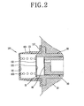
- FIG. 2 shows one example of a conventional structure of a discharge valve assembly of the reciprocating compressor.
- the discharge valve assembly 100 of the conventional compressor comprises: a discharge cover 101 for covering an inner space of the cylinder 50; a discharge valve 102 inserted in the discharge cover 101, for opening or closing the inner space of the cylinder 50; and a valve spring 103 for elastically supporting the discharge valve 102, wherein the discharge cover 101 is formed as a cap shape with a certain thickness.
- a fixing portion 112 is bent and extends from one side of a cylindrical portion 111 having certain length and outer diameter, and is coupled to the front frame 20, and a discharge opening 113 to which the gas discharge pipe 2 is connected is formed at one side of the cylindrical portion 111.
- the discharge valve 102 is formed as a circular compression plane 123 whose one side is coupled to a spring and whose other side blocks the inner space of the cylinder 50.
- the valve spring 103 is a coil spring having a certain length.
- One side of the valve spring 103 is coupled to the discharge valve, and its other side contacts with and is supported by an inner surface of the discharge cover.
- the compression plane 123 of the discharge valve comes in contact with a contact surface (S1), an end surface of the cylinder 50.
- an inner surface of the discharge cover, which is in contact with the valve spring 103, is a plane parallel to the contact surface (S1) of the cylinder 50, which comes in contact with the compression plane 123 of the discharge valve.
- the compression plane 123 of the discharge valve adheres to the contact surface (S1) of the cylinder 50 by a pressure difference of the inner space of the cylinder 50, and simultaneously, the suction valve 90 is opened, allowing a gas to be introduced into the inner space of the cylinder 50 through a passage formed in the piston 60.
- the suction valve 90 blocks a gas passage of the piston 60, thereby gradually compressing the gas sucked in the inner space of the cylinder 50.
- the discharge valve 102 supported by the valve spring 103 is opened, thereby discharging a compressed gas. By continuously repeating such processes, the gas is compressed.
- a section of the inner space of the cylinder where a gas is compressed is a circular shape
- the discharge valve 102 for opening or closing the inner space is formed as a circular shape.
- the inner space of the cylinder 50 and the discharge valve 102 for opening or closing the inner space have the shapes which can allow a maximum discharge area. Therefore, the flow of a discharged gas is smooth, and a large amount of discharge gas is discharged at a time, thereby improving efficiency.
- the discharge valve assembly having such a structure has the following problems.
- stiffness of the valve spring 103 which elastically supports the discharge valve 102 is low.
- a range of the movement becomes wide, thereby increasing the amount of impact generated by contact with the cylinder 50. Accordingly, a valve contact noise of high frequency is greatly generated.
- the discharge valve is opened when a force due to pressure of a compression space formed by the piston and the discharge valve is greater than the sum of an adhesive force of oil at the contact surface, a force due to a valve spring and a force due to pressure in the discharge cover. This makes the piston unnecessarily work on a fluid, thereby resulting in overcompression-related loss.
- an object of the present invention is to provide a discharge valve assembly of a reciprocating compressor capable of minimizing noise generation and the amount of contact impact.
- a discharge valve assembly of a reciprocating compressor comprising: a discharge valve for opening or closing a compression space for compressing a refrigerant in a cylinder; a valve spring for elastically supporting the discharge valve as its one end is connected to the discharge valve; a discharge cover provided with a support surface connected to the valve spring, and covering an end of the cylinder, receiving the discharge valve and the valve spring and simultaneously forming a discharge space of a refrigerant; and a buffer member attached to an outer mounting surface of the cylinder, for lessening an impact by contacting with the discharge valve before the discharge valve comes in contact with the cylinder to close the compression space of the cylinder.
- Figure 3 is a sectional view showing a first embodiment of a discharge valve assembly of a reciprocating compressor in accordance with the present invention.
- the discharge valve assembly 200 of the reciprocating compressor in accordance with the present invention includes: a discharge valve 202 for opening or closing a compression space (P) for compressing a refrigerant in a cylinder 150; a valve spring 203 elastically supporting the discharge valve 202 as its one end is connected to the discharge valve 202; a discharge cover 201 provided with a support surface 204 connected to the valve spring 203, for covering an end of the cylinder 150, receiving the discharge valve 202 and the valve spring 230 and forming a discharge space (D) of a refrigerant; and a buffer member 300 attached to an outer mounting surface 320 of the cylinder 150, for lessening an impact by coming in contact with the discharge valve 202 in advance before the discharge valve 202 contacts with the cylinder 150 to close the compression space (P) of the cylinder 150.
- a discharge valve 202 for opening or closing a compression space (P) for compressing a refrigerant in a cylinder 150
- a valve spring 203 elastically supporting the discharge valve
- the cylinder 150 is supported by and installed at the front frame 20.
- a piston 60 is inserted in the cylinder 150, and the piston 60 is coupled to a mover of a reciprocating driving motor within a compression space of the cylinder 150.
- a step is formed at one side end of the cylinder 150, and a contact surface 310 contacting with the discharge valve 202 and a mounting surface 320 to which the buffer member 300 to be explained later is mounted are formed thereat.
- a gas passage 61 is penetratingly formed in the piston 60, and a suction valve 90 for opening or closing the gas passage 61 is mounted at its one side end.
- the discharge cover 201 is provided with a cylindrical portion 211 having a receiving space therein and formed as a cylindrical shape whose one side is opened, with certain thickness and length; and a fixing portion 212 bent and extending from the other side of the cylindrical portion 211.
- the fixing portion 212 is coupled to the front frame 20, so that the discharge cover 201 covers a portion including a contact surface 310 side of the cylinder.
- a discharge opening 213 for discharging a compressed refrigerant is formed at one side of the cylindrical portion 211.
- the discharge opening 213 is connected with a gas discharge pipe (not shown).
- the discharge valve 202 its one side is a compression plane 223 contacting with the contact surface 310 of the cylinder, and a valve spring 203 is coupled to its other side.
- the discharge valve 202 contacts with the contact surface 310 of the cylinder with its compression plane 223 hermetically sealing the compression space (P) of the cylinder 150.
- the valve spring 203 is a coil spring having a certain length.
- valve spring 203 its one side is coupled to the discharge valve 202, and the other side is in contact with and supported by the support surface 204 of the discharge cover 201.
- the compression plane 223 of the discharge valve contacts with the contact surface 310, an end surface of the cylinder 150, and the support surface 204 of the discharge cover, which is in contact with the valve spring 203, is a plane parallel to the contact surface 310 of the cylinder 150, which comes in contact with the compression plane 223 of the discharge valve.
- the buffer member 300 is mounted to a mounting surface 320 of the cylinder 150.
- the buffer member 300 is formed to have a height higher than that (H) between the mounting surface 320 and the contact surface 310 by about 1 mm or higher in a state that the buffer member 30 does not receive any load.
- the discharge valve 202 when closed, the discharge valve 202 preferably begins to contact with the buffer member 300 at a spot where a distance between the discharge valve 202 and the contact surface 301 is 1 mm or more.
- the buffer member 300 is one coil spring, and is mounted to a circumference of the mounting surface 320, or, as the buffer member 300, a plurality of coil springs may be disposed at the circumference of the mounting surface 320.
- the buffer member 300 may be formed as a wave spring.
- the buffer member 300 may be formed by using an elastic material such as a sponge.
- the mounting surface 320 is placed at a place where one side end of the cylinder 150 is stepped. Specifically, a protrusion of the stepped portion of the cylinder 150 becomes a contact surface 310 coming in contact with the compression plane 223 of the discharge valve 202, and a non-protrusion becomes a mounting surface 320 to which the buffer member 300 is mounted.
- a height (H) between the mounting surface 320 and the contact surface 310 may have a certain value, but the value may be zero. Namely, the mounting surface 320 and the contact surface 310 may be on the same plane.
- a height of the buffer member 300 is set to be higher than 1 mm or more in a state that the buffer member 300 does not receive a load at all, the same effect as in the present invention would be achieved, provided a special means for fixing the buffer member 300 to one side of the cylinder 150 is installed.
- the piston 60 linearly reciprocates in the cylinder 150 upon receiving a driving force of the driving motor.
- the suction valve 90 blocks a gas passage of the piston 60, thereby gradually compressing a gas sucked in the compression space (P) of the cylinder 150. If the gas reaches a set compression state, the discharge valve 202 supported by the valve spring 203 is opened, thereby discharging the compressed gas.
- the compression plane 223 of the discharge valve 202 adheres to the contact surface 310 of the cylinder by a pressure difference of an inner space of the cylinder 150, and simultaneously, the suction valve 90 is opened, so that a gas is introduced into an inner space of the cylinder 150 through the gas passage.
- the buffer member 300 is positioned at the mounting surface 320, and a height of the buffer member 300 is higher than a height (H) at which one side of the cylinder protrudes from the mounting surface 320 to the contact surface 310. Therefore, the buffer member 300 comes in contact with the discharge valve 202 before the discharge valve 202 contacts with the contact surface 310, thereby distributing the amount of an impact. Namely, the buffer member 300 lessens an impact before the compression plane 223 of the discharge valve 202 contacts with the contact surface 310 of the cylinder.
- Figure 4 is a sectional view showing a second embodiment of a discharge valve assembly of the reciprocating compressor in accordance with the present invention.
- a discharge valve 202 is formed to be stepped, and, to this end, a contact member 250 is attached to the discharge valve 202 of the first embodiment, facing the piston 60.
- an outer diameter of the contact member 250 is the same as that of the contact surface 310.
- the compression plane 223 is formed on the contact member 250, and the buffer member 300 contacts with the discharge valve 202, except its portion where the contact member 250 is placed.
- the contact member 250 is adjusted in thickness to control a distance between the buffer member 300 and the discharge valve 202, and is formed on the discharge valve 202.
- the discharge valve assembly of the reciprocating motor in accordance with the present invention is provided with a buffer member 300 for absorbing an impact by contacting with the discharge valve 202 before the discharge valve 202 comes in contact with the cylinder. Therefore, when the inner space of the cylinder 150 is opened or closed by a pressure difference generated by a reciprocation of the piston 60, the amount of an impact between the discharge valve 202 and the cylinder 150 is decreased, thereby reducing contact noise generation of the discharge valve 202 and improving reliability.
- contact noise is desirably reduced by about 4dB.
- the discharge valve is opened when a force due to pressure of a compression space formed by the piston and the discharge valve is greater than the sum of an adhesive force of oil at the contact surface, a force due to a valve spring and a force due to pressure in the discharge cover.
- the present invention is advantageous in that an overcompression-related loss can be reduced because the discharge valve is more easily opened by the buffer member,
Landscapes
- Engineering & Computer Science (AREA)
- General Engineering & Computer Science (AREA)
- Mechanical Engineering (AREA)
- Compressor (AREA)
- Compressors, Vaccum Pumps And Other Relevant Systems (AREA)
Abstract
Description
- The present invention relates to a discharge valve assembly of a reciprocating compressor, and particularly, to a discharge valve assembly of a reciprocating compressor capable of minimizing noise generation and the amount of contact impact.
- In general, a reciprocating compressor is an apparatus that sucks and compresses a refrigerant gas as a piston linearly reciprocates in a cylinder. Such a reciprocating compressor is divided into two types according to the driving mechanism. Of the two types, one is that a rotating movement of a motor is converted into a linear reciprocation and the linear reciprocation is transferred to the piston, and the other one is that a linear reciprocation of the motor is directly transferred to the piston.
- Figures 1 shows one example of a reciprocating compressor which is operated in such a manner that a linear reciprocation of a motor is directly transferred to a piston. As shown, the reciprocating compressor comprises: a
casing 10 coupled to a gas suction pipe 1 and agas discharge pipe 2; afront frame 20 and amiddle frame 30 installed in thecasing 10 at a predetermined distance therebetween and elastically supported; adriving motor 40 mounted between thefront frame 20 and themiddle frame 30, for generating a linearly reciprocating driving force; acylinder 50 inserted in thefirst frame 20; apiston 60 linearly reciprocating in thecylinder 50 upon receiving a driving force of thedriving motor 40; arear frame 70 for covering thepiston 60; aresonant spring 80 for elastically supporting thepiston 60 to thereby induce resonance; asuction valve 90 coupled to a front end surface of thepiston 60, for controlling the flow of a gas which is introduced into thecylinder 50 by the linear reciprocation of thepiston 60; and adischarge valve assembly 100 installed at one side of thecylinder 50, for controlling discharging of a compressed gas which is compressed in the cylinder by the linear reciprocation of thepiston 60. - The
driving motor 40 includes: anouter stator 41 mounted between thefront frame 20 and themiddle frame 30; aninner stator 42 inserted in theouter stator 41 and mounted at thefront frame 20; awinding coil 43 coupled to theouter stator 41; and amover 44 installed between theouter stator 41 and theinner stator 42 to be linearly movable. Themover 44 includes acylindrical holder 45 and a plurality ofmagnets 46 coupled to theholder 45, and theholder 45 is connected to thepiston 60. - The
discharge valve assembly 100 includes adischarge cover 101 for covering an inner space of thecylinder 50; adischarge valve 102 positioned in thedischarge cover 101, for opening or closing the inner space of the cylinder; and aspring 103 for elastically supporting thedischarge valve 102. Thegas discharge pipe 2 is connected to thedischarge cover 101. - Undescribed
reference mark 104 is a coupling bolt, and 105 is a nut. - The operation of the reciprocating compressor having such a structure will now be described.
- First, when power is applied to the compressor, a linearly reciprocating driving force is generated at the
driving motor 40. Thus, themover 44 of the driving motor linearly reciprocates, and a linearly reciprocating driving force of themover 44 is transferred to thepiston 60, so that thepiston 60 linearly reciprocates in the inner space of thecylinder 50. By a pressure difference generated in thecylinder 50 due to a linear reciprocation of thepiston 60 in the inner space of thecylinder 50, thesuction valve 90 and thedischarge valve assembly 100 open or close a gas passage, whereby a gas is sucked into, compressed in and discharged from thecylinder 50. The compressed gas discharged from the inner space of thecylinder 50 passes the inside of thedischarge cover 101 and then is discharged through thegas discharge pipe 2. Such processes are continuously repeated to compress a gas. - Meanwhile, in the reciprocating compressor, the
discharge valve assembly 100 for discharging a compressed gas according to a linear reciprocation of thepiston 50 affects how much noise is generated. Also, the operation of thedischarge valve assembly 100 affects flow resistance of a discharged gas, thereby affecting the amount of the discharged gas. Accordingly, researches on thedischarge valve assembly 100 are very important in improving reliability and efficiency, and thus the researches thereon are actively ongoing. - Figure 2 shows one example of a conventional structure of a discharge valve assembly of the reciprocating compressor. As shown, the
discharge valve assembly 100 of the conventional compressor comprises: adischarge cover 101 for covering an inner space of thecylinder 50; adischarge valve 102 inserted in thedischarge cover 101, for opening or closing the inner space of thecylinder 50; and avalve spring 103 for elastically supporting thedischarge valve 102, wherein thedischarge cover 101 is formed as a cap shape with a certain thickness. Namely, as for thedischarge cover 101, afixing portion 112 is bent and extends from one side of acylindrical portion 111 having certain length and outer diameter, and is coupled to thefront frame 20, and adischarge opening 113 to which thegas discharge pipe 2 is connected is formed at one side of thecylindrical portion 111. - The
discharge valve 102 is formed as acircular compression plane 123 whose one side is coupled to a spring and whose other side blocks the inner space of thecylinder 50. - The
valve spring 103 is a coil spring having a certain length. - One side of the
valve spring 103 is coupled to the discharge valve, and its other side contacts with and is supported by an inner surface of the discharge cover. At this time, thecompression plane 123 of the discharge valve comes in contact with a contact surface (S1), an end surface of thecylinder 50. And an inner surface of the discharge cover, which is in contact with thevalve spring 103, is a plane parallel to the contact surface (S1) of thecylinder 50, which comes in contact with thecompression plane 123 of the discharge valve. - The operation of the discharge valve assembly of the conventional reciprocating compressor having such a structure will now be described in detail.
- First, when the
piston 60 moves from a top dead point to a bottom dead point, thecompression plane 123 of the discharge valve adheres to the contact surface (S1) of thecylinder 50 by a pressure difference of the inner space of thecylinder 50, and simultaneously, thesuction valve 90 is opened, allowing a gas to be introduced into the inner space of thecylinder 50 through a passage formed in thepiston 60. - And, when the
piston 60 moves from a bottom dead point to a top dead point, thesuction valve 90 blocks a gas passage of thepiston 60, thereby gradually compressing the gas sucked in the inner space of thecylinder 50. When the gas reaches a set compression state, thedischarge valve 102 supported by thevalve spring 103 is opened, thereby discharging a compressed gas. By continuously repeating such processes, the gas is compressed. - In the discharge valve assembly having such a structure, a section of the inner space of the cylinder where a gas is compressed is a circular shape, and the
discharge valve 102 for opening or closing the inner space is formed as a circular shape. Thus, the inner space of thecylinder 50 and thedischarge valve 102 for opening or closing the inner space have the shapes which can allow a maximum discharge area. Therefore, the flow of a discharged gas is smooth, and a large amount of discharge gas is discharged at a time, thereby improving efficiency. - However, the discharge valve assembly having such a structure has the following problems. In order to make a movement of the
discharge valve 102 smooth, stiffness of thevalve spring 103 which elastically supports thedischarge valve 102 is low. For this reason, when thedischarge valve 102 moves, a range of the movement becomes wide, thereby increasing the amount of impact generated by contact with thecylinder 50. Accordingly, a valve contact noise of high frequency is greatly generated. - In addition, the discharge valve is opened when a force due to pressure of a compression space formed by the piston and the discharge valve is greater than the sum of an adhesive force of oil at the contact surface, a force due to a valve spring and a force due to pressure in the discharge cover. This makes the piston unnecessarily work on a fluid, thereby resulting in overcompression-related loss.
- Therefore, an object of the present invention is to provide a discharge valve assembly of a reciprocating compressor capable of minimizing noise generation and the amount of contact impact.
- To achieve these and other advantages and in accordance with the purpose of the present invention, as embodied and broadly described herein, there is provided a discharge valve assembly of a reciprocating compressor comprising: a discharge valve for opening or closing a compression space for compressing a refrigerant in a cylinder; a valve spring for elastically supporting the discharge valve as its one end is connected to the discharge valve; a discharge cover provided with a support surface connected to the valve spring, and covering an end of the cylinder, receiving the discharge valve and the valve spring and simultaneously forming a discharge space of a refrigerant; and a buffer member attached to an outer mounting surface of the cylinder, for lessening an impact by contacting with the discharge valve before the discharge valve comes in contact with the cylinder to close the compression space of the cylinder.
- The foregoing and other objects, features, aspects and advantages of the present invention will become more apparent from the following detailed description of the present invention when taken in conjunction with the accompanying drawings.
- The accompanying drawings, which are included to provide a further understanding of the invention and are incorporated in and constitute a unit of this specification, illustrate embodiments of the invention and together with the description serve to explain the principles of the invention.
- In the drawings:
- Figure 1 is a sectional view showing a conventional reciprocating compressor;
- Figure 2 is a sectional view showing a discharge valve assembly of the conventional reciprocating compressor;
- Figure 3 is a sectional view showing a first embodiment of a discharge valve assembly of a reciprocating compressor in accordance with the present invention; and
- Figure 4 is a sectional view showing a second embodiment of a discharge valve assembly of a reciprocating compressor in accordance with the present invention.
- Reference will now be made in detail to the preferred embodiments of the present invention, examples of which are illustrated in the accompanying drawings. Descriptions on the same details as those in the conventional art will be omitted.
- Figure 3 is a sectional view showing a first embodiment of a discharge valve assembly of a reciprocating compressor in accordance with the present invention.
- As shown, the
discharge valve assembly 200 of the reciprocating compressor in accordance with the present invention includes: adischarge valve 202 for opening or closing a compression space (P) for compressing a refrigerant in acylinder 150; avalve spring 203 elastically supporting thedischarge valve 202 as its one end is connected to thedischarge valve 202; adischarge cover 201 provided with asupport surface 204 connected to thevalve spring 203, for covering an end of thecylinder 150, receiving thedischarge valve 202 and the valve spring 230 and forming a discharge space (D) of a refrigerant; and abuffer member 300 attached to anouter mounting surface 320 of thecylinder 150, for lessening an impact by coming in contact with thedischarge valve 202 in advance before thedischarge valve 202 contacts with thecylinder 150 to close the compression space (P) of thecylinder 150. - The
cylinder 150 is supported by and installed at thefront frame 20. - A
piston 60 is inserted in thecylinder 150, and thepiston 60 is coupled to a mover of a reciprocating driving motor within a compression space of thecylinder 150. - A step is formed at one side end of the
cylinder 150, and acontact surface 310 contacting with thedischarge valve 202 and amounting surface 320 to which thebuffer member 300 to be explained later is mounted are formed thereat. - A
gas passage 61 is penetratingly formed in thepiston 60, and asuction valve 90 for opening or closing thegas passage 61 is mounted at its one side end. - The
discharge cover 201 is provided with acylindrical portion 211 having a receiving space therein and formed as a cylindrical shape whose one side is opened, with certain thickness and length; and a fixingportion 212 bent and extending from the other side of thecylindrical portion 211. The fixingportion 212 is coupled to thefront frame 20, so that thedischarge cover 201 covers a portion including acontact surface 310 side of the cylinder. Adischarge opening 213 for discharging a compressed refrigerant is formed at one side of thecylindrical portion 211. Like the conventional art, thedischarge opening 213 is connected with a gas discharge pipe (not shown). - As for the
discharge valve 202, its one side is acompression plane 223 contacting with thecontact surface 310 of the cylinder, and avalve spring 203 is coupled to its other side. Thedischarge valve 202 contacts with thecontact surface 310 of the cylinder with itscompression plane 223 hermetically sealing the compression space (P) of thecylinder 150. - The
valve spring 203 is a coil spring having a certain length. - As for the
valve spring 203, its one side is coupled to thedischarge valve 202, and the other side is in contact with and supported by thesupport surface 204 of thedischarge cover 201. At this time, thecompression plane 223 of the discharge valve contacts with thecontact surface 310, an end surface of thecylinder 150, and thesupport surface 204 of the discharge cover, which is in contact with thevalve spring 203, is a plane parallel to thecontact surface 310 of thecylinder 150, which comes in contact with thecompression plane 223 of the discharge valve. - The
buffer member 300 is mounted to a mountingsurface 320 of thecylinder 150. - Preferably, the
buffer member 300 is formed to have a height higher than that (H) between the mountingsurface 320 and thecontact surface 310 by about 1 mm or higher in a state that thebuffer member 30 does not receive any load. Namely, when closed, thedischarge valve 202 preferably begins to contact with thebuffer member 300 at a spot where a distance between thedischarge valve 202 and the contact surface 301 is 1 mm or more. - Preferably, the
buffer member 300 is one coil spring, and is mounted to a circumference of the mountingsurface 320, or, as thebuffer member 300, a plurality of coil springs may be disposed at the circumference of the mountingsurface 320. - The
buffer member 300 may be formed as a wave spring. - Also, the
buffer member 300 may be formed by using an elastic material such as a sponge. - The mounting
surface 320 is placed at a place where one side end of thecylinder 150 is stepped. Specifically, a protrusion of the stepped portion of thecylinder 150 becomes acontact surface 310 coming in contact with thecompression plane 223 of thedischarge valve 202, and a non-protrusion becomes a mountingsurface 320 to which thebuffer member 300 is mounted. A height (H) between the mountingsurface 320 and thecontact surface 310 may have a certain value, but the value may be zero. Namely, the mountingsurface 320 and thecontact surface 310 may be on the same plane. In such case, if a height of thebuffer member 300 is set to be higher than 1 mm or more in a state that thebuffer member 300 does not receive a load at all, the same effect as in the present invention would be achieved, provided a special means for fixing thebuffer member 300 to one side of thecylinder 150 is installed. - The operational effect of the discharge valve assembly of the reciprocating compressor in accordance with the present invention will now be described.
- The
piston 60 linearly reciprocates in thecylinder 150 upon receiving a driving force of the driving motor. At this time, when thepiston 60 moves from a bottom dead point to a top dead point, thesuction valve 90 blocks a gas passage of thepiston 60, thereby gradually compressing a gas sucked in the compression space (P) of thecylinder 150. If the gas reaches a set compression state, thedischarge valve 202 supported by thevalve spring 203 is opened, thereby discharging the compressed gas. - And, when the piston 230 moves from a top dead point to a bottom dead point, the
compression plane 223 of thedischarge valve 202 adheres to thecontact surface 310 of the cylinder by a pressure difference of an inner space of thecylinder 150, and simultaneously, thesuction valve 90 is opened, so that a gas is introduced into an inner space of thecylinder 150 through the gas passage. At this time, thebuffer member 300 is positioned at the mountingsurface 320, and a height of thebuffer member 300 is higher than a height (H) at which one side of the cylinder protrudes from the mountingsurface 320 to thecontact surface 310. Therefore, thebuffer member 300 comes in contact with thedischarge valve 202 before thedischarge valve 202 contacts with thecontact surface 310, thereby distributing the amount of an impact. Namely, thebuffer member 300 lessens an impact before thecompression plane 223 of thedischarge valve 202 contacts with thecontact surface 310 of the cylinder. - By continuously repeating such processes, a gas is sucked, compressed and discharged.
- Figure 4 is a sectional view showing a second embodiment of a discharge valve assembly of the reciprocating compressor in accordance with the present invention.
- In case of the second embodiment, a
discharge valve 202 is formed to be stepped, and, to this end, acontact member 250 is attached to thedischarge valve 202 of the first embodiment, facing thepiston 60. Preferably, an outer diameter of thecontact member 250 is the same as that of thecontact surface 310. - In the embodiment, the
compression plane 223 is formed on thecontact member 250, and thebuffer member 300 contacts with thedischarge valve 202, except its portion where thecontact member 250 is placed. Thecontact member 250 is adjusted in thickness to control a distance between thebuffer member 300 and thedischarge valve 202, and is formed on thedischarge valve 202. - As so far described, the discharge valve assembly of the reciprocating motor in accordance with the present invention is provided with a
buffer member 300 for absorbing an impact by contacting with thedischarge valve 202 before thedischarge valve 202 comes in contact with the cylinder. Therefore, when the inner space of thecylinder 150 is opened or closed by a pressure difference generated by a reciprocation of thepiston 60, the amount of an impact between thedischarge valve 202 and thecylinder 150 is decreased, thereby reducing contact noise generation of thedischarge valve 202 and improving reliability. - According to experiments, contact noise is desirably reduced by about 4dB.
- In addition, the discharge valve is opened when a force due to pressure of a compression space formed by the piston and the discharge valve is greater than the sum of an adhesive force of oil at the contact surface, a force due to a valve spring and a force due to pressure in the discharge cover. This makes the piston unnecessarily work on a fluid, thereby resulting in overcompression-related loss. However, the present invention is advantageous in that an overcompression-related loss can be reduced because the discharge valve is more easily opened by the buffer member,
- As the present invention may be embodied in several forms without departing from the spirit or essential characteristics thereof, it should also be understood that the above-described embodiments are not limited by any of the details of the foregoing description, unless otherwise specified, but rather should be construed broadly within its spirit and scope as defined in the appended claims, and therefore all changes and modifications that fall within the metes and bounds of the claims, or equivalence of such metes and bounds are therefore intended to be embraced by the appended claims.
Claims (11)
- A discharge valve assembly of a reciprocating compressor comprising:a discharge valve for opening or closing a compression space for compressing a refrigerant in a cylinder;a valve spring for elastically supporting the discharge valve as its one end is connected to the discharge valve;a discharge cover provided with a support surface connected to the valve spring, and covering an end of the cylinder, receiving the discharge valve and the valve spring and simultaneously forming a discharge space of a refrigerant; anda buffer member attached to an outer mounting surface of the cylinder, for lessening an impact by contacting with the discharge valve before the discharge valve comes in contact with the cylinder to close the compression space of the cylinder.
- The assembly of claim 1, wherein a height of the buffer member, which is measured vertically from its mounting surface, is higher than that from the mounting surface to a contact surface on which the discharge valve and the cylinder contact with each other, by 1 mm or higher.
- The assembly of claim 1, wherein a height of the buffer member is 1 mm or higher when measured vertically from a mounting surface, and the mounting surface and a contact surface on which the discharge valve contacts with the cylinder are positioned on the same plane.
- The assembly of claim 1, wherein the buffer member is one coil spring, and is mounted to a circumference of the mounting surface.
- The assembly of claim 1, wherein the buffer member is a wave spring.
- The assembly of claim 1, wherein the buffer member is a plurality of coil springs, and is disposed at a circumference of the mounting surface.
- The assembly of claim 1, wherein the buffer member is an elastic material.
- The assembly of claim 1, wherein the buffer member is a sponge.
- The assembly of claim 1, wherein one end of the cylinder is stepped, wherein a protrusion forms a contact surface contacting with the discharge valve and a non-protrusion forms a mounting surface on which the buffer member is mounted.
- The assembly of claim 1, wherein the discharge valve further comprises:a contact member attached toward the piston .
- The assembly of claim 10, wherein an outer diameter of the contact member is the same as that of the contact surface on which the discharge valve contacts with the cylinder.
Applications Claiming Priority (1)
| Application Number | Priority Date | Filing Date | Title |
|---|---|---|---|
| KR1020040090394A KR20060041041A (en) | 2004-11-08 | 2004-11-08 | Discharge valve assembly of reciprocating compressor |
Publications (3)
| Publication Number | Publication Date |
|---|---|
| EP1655487A2 true EP1655487A2 (en) | 2006-05-10 |
| EP1655487A3 EP1655487A3 (en) | 2007-01-24 |
| EP1655487B1 EP1655487B1 (en) | 2008-02-27 |
Family
ID=34937238
Family Applications (1)
| Application Number | Title | Priority Date | Filing Date |
|---|---|---|---|
| EP05012084A Not-in-force EP1655487B1 (en) | 2004-11-08 | 2005-06-04 | Discharge valve assembly of reciprocating compressor |
Country Status (6)
| Country | Link |
|---|---|
| US (1) | US7553137B2 (en) |
| EP (1) | EP1655487B1 (en) |
| JP (1) | JP2006132525A (en) |
| KR (1) | KR20060041041A (en) |
| CN (1) | CN100480508C (en) |
| DE (1) | DE602005004987T2 (en) |
Families Citing this family (4)
| Publication number | Priority date | Publication date | Assignee | Title |
|---|---|---|---|---|
| KR100836057B1 (en) * | 2007-01-31 | 2008-06-09 | 엘지전자 주식회사 | Reciprocating compressor |
| KR200470033Y1 (en) * | 2012-05-10 | 2013-11-25 | (주)신한전기 | Check valve of variable capacity compressor vehicle |
| US20170218935A1 (en) * | 2014-07-31 | 2017-08-03 | Burckhardt Compression Ag | Housing upper part of a labyrinth piston compressor and method for cooling same, and labyrinth piston compressor |
| KR102229548B1 (en) * | 2019-12-10 | 2021-03-19 | 엘지전자 주식회사 | Compressor |
Citations (4)
| Publication number | Priority date | Publication date | Assignee | Title |
|---|---|---|---|---|
| US2613870A (en) * | 1949-05-26 | 1952-10-14 | Int Harvester Co | Compressor cylinder head assembly |
| US4627464A (en) * | 1985-12-20 | 1986-12-09 | Ingersoll-Rand Company | Unidirectional, fluid control valve |
| WO1997007334A1 (en) * | 1995-08-21 | 1997-02-27 | Lg Electronics Inc. | Axial flow valve system for linear compressor |
| WO2004081379A2 (en) * | 2003-03-11 | 2004-09-23 | Lg Electronics Inc. | Reciprocating compressor having vibration attenuating supporting unit |
Family Cites Families (15)
| Publication number | Priority date | Publication date | Assignee | Title |
|---|---|---|---|---|
| US3039487A (en) * | 1960-09-26 | 1962-06-19 | American Motors Corp | Refrigerating apparatus |
| US3508849A (en) * | 1968-01-30 | 1970-04-28 | Du Pont | Compressor valve |
| US3489334A (en) * | 1968-03-25 | 1970-01-13 | Frick Co | Discharge valve for reciprocating compressors |
| JPS57164362U (en) * | 1981-04-13 | 1982-10-16 | ||
| JPH09144659A (en) * | 1995-11-22 | 1997-06-03 | Sanyo Electric Co Ltd | Refrigerant compressor |
| JPH10184956A (en) * | 1996-12-27 | 1998-07-14 | Jiinasu:Kk | Check valve for feeding fluid under high pressure |
| KR20010096179A (en) * | 2000-04-17 | 2001-11-07 | 이충전 | Noise Decrease Device of Exhaust Valve in a Sealed Type Compressor |
| US6612338B2 (en) * | 2000-05-25 | 2003-09-02 | Siemens Automotive Inc. | Fuel tank pressure control valve |
| US6349473B1 (en) * | 2000-08-11 | 2002-02-26 | Alterra Holdings Corporation | Utility knife |
| KR100422368B1 (en) * | 2001-11-21 | 2004-03-11 | 삼성광주전자 주식회사 | Cylinder assembly for compressor having member to absorbing suction shocking and noise |
| KR20030054976A (en) | 2001-12-26 | 2003-07-02 | 엘지전자 주식회사 | Device for reducing noise of reciprocating compressor |
| ES2276055T3 (en) * | 2002-04-23 | 2007-06-16 | Teleflex Gfi Control Systems L.P. | PRESSURE RELIEF DEVICE. |
| US7063520B2 (en) * | 2002-05-06 | 2006-06-20 | Lg Electronics Inc. | Suction valve assembly of reciprocating compressor |
| JP2004108271A (en) | 2002-09-19 | 2004-04-08 | Honda Motor Co Ltd | Compressor |
| KR20040042000A (en) * | 2002-11-12 | 2004-05-20 | 삼성광주전자 주식회사 | Valve for hermetic compressor |
-
2004
- 2004-11-08 KR KR1020040090394A patent/KR20060041041A/en not_active Application Discontinuation
-
2005
- 2005-06-04 EP EP05012084A patent/EP1655487B1/en not_active Not-in-force
- 2005-06-04 DE DE602005004987T patent/DE602005004987T2/en active Active
- 2005-06-14 US US11/151,267 patent/US7553137B2/en not_active Expired - Fee Related
- 2005-07-26 CN CNB2005100849762A patent/CN100480508C/en not_active Expired - Fee Related
- 2005-08-04 JP JP2005226392A patent/JP2006132525A/en active Pending
Patent Citations (4)
| Publication number | Priority date | Publication date | Assignee | Title |
|---|---|---|---|---|
| US2613870A (en) * | 1949-05-26 | 1952-10-14 | Int Harvester Co | Compressor cylinder head assembly |
| US4627464A (en) * | 1985-12-20 | 1986-12-09 | Ingersoll-Rand Company | Unidirectional, fluid control valve |
| WO1997007334A1 (en) * | 1995-08-21 | 1997-02-27 | Lg Electronics Inc. | Axial flow valve system for linear compressor |
| WO2004081379A2 (en) * | 2003-03-11 | 2004-09-23 | Lg Electronics Inc. | Reciprocating compressor having vibration attenuating supporting unit |
Also Published As
| Publication number | Publication date |
|---|---|
| EP1655487B1 (en) | 2008-02-27 |
| DE602005004987T2 (en) | 2008-06-12 |
| KR20060041041A (en) | 2006-05-11 |
| JP2006132525A (en) | 2006-05-25 |
| US20060099091A1 (en) | 2006-05-11 |
| CN1773113A (en) | 2006-05-17 |
| DE602005004987D1 (en) | 2008-04-10 |
| US7553137B2 (en) | 2009-06-30 |
| CN100480508C (en) | 2009-04-22 |
| EP1655487A3 (en) | 2007-01-24 |
Similar Documents
| Publication | Publication Date | Title |
|---|---|---|
| US6755627B2 (en) | Linear compressor | |
| US7124678B2 (en) | Apparatus for preventing abrasion in reciprocal compressor | |
| US7591638B2 (en) | Structure for fixing motor stator of reciprocating compressor | |
| KR100504858B1 (en) | Discharge apparatus for reciprocating compressor | |
| JP4662741B2 (en) | Reciprocating compressor | |
| US20170016436A1 (en) | Reciprocating compressor | |
| US6729861B2 (en) | Reciprocating compressor with support springs placed between support members for radial compactness | |
| EP1655487B1 (en) | Discharge valve assembly of reciprocating compressor | |
| US20040047751A1 (en) | Reciprocating compressor | |
| US20040047750A1 (en) | Reciprocating compressor | |
| US7275561B2 (en) | Discharging valve assembly of reciprocating compressor | |
| US20050034926A1 (en) | Lubricating oil supply apparatus of reciprocating compressor | |
| CN210949023U (en) | Linear compressor | |
| KR100406305B1 (en) | Linear compressor | |
| US11231024B2 (en) | Compressor comprising an upper shell and a lower shell wherein the upper shell comprises an upper protrusion comprising a first protrusion and a second protrusion comprising a transition and an approximately flat shape | |
| JP2002317761A (en) | Linear compressor | |
| US20040228746A1 (en) | Suction valve assembly of reciprocating compressor | |
| US20040213682A1 (en) | Hermetic compressor | |
| KR100622256B1 (en) | Support for a motor stator of a compressor | |
| KR100469457B1 (en) | Reciprocating compressor | |
| CN110630468A (en) | Linear compressor | |
| KR100620049B1 (en) | Structure for supporting valve in recipro compressor | |
| KR100527580B1 (en) | Shock absorbing apparatus of reciprocating compressor | |
| KR20070087883A (en) | Structure preventing vibration in a linear compressor | |
| KR20050061955A (en) | Linear compressor |
Legal Events
| Date | Code | Title | Description |
|---|---|---|---|
| PUAI | Public reference made under article 153(3) epc to a published international application that has entered the european phase |
Free format text: ORIGINAL CODE: 0009012 |
|
| AK | Designated contracting states |
Kind code of ref document: A2 Designated state(s): AT BE BG CH CY CZ DE DK EE ES FI FR GB GR HU IE IS IT LI LT LU MC NL PL PT RO SE SI SK TR |
|
| AX | Request for extension of the european patent |
Extension state: AL BA HR LV MK YU |
|
| PUAL | Search report despatched |
Free format text: ORIGINAL CODE: 0009013 |
|
| AK | Designated contracting states |
Kind code of ref document: A3 Designated state(s): AT BE BG CH CY CZ DE DK EE ES FI FR GB GR HU IE IS IT LI LT LU MC NL PL PT RO SE SI SK TR |
|
| AX | Request for extension of the european patent |
Extension state: AL BA HR LV MK YU |
|
| RIC1 | Information provided on ipc code assigned before grant |
Ipc: F04B 39/10 20060101AFI20050711BHEP Ipc: F04B 35/04 20060101ALI20061221BHEP Ipc: F04B 39/00 20060101ALI20061221BHEP |
|
| 17P | Request for examination filed |
Effective date: 20070207 |
|
| 17Q | First examination report despatched |
Effective date: 20070309 |
|
| GRAP | Despatch of communication of intention to grant a patent |
Free format text: ORIGINAL CODE: EPIDOSNIGR1 |
|
| AKX | Designation fees paid |
Designated state(s): DE FR GB |
|
| GRAS | Grant fee paid |
Free format text: ORIGINAL CODE: EPIDOSNIGR3 |
|
| GRAA | (expected) grant |
Free format text: ORIGINAL CODE: 0009210 |
|
| AK | Designated contracting states |
Kind code of ref document: B1 Designated state(s): DE FR GB |
|
| REG | Reference to a national code |
Ref country code: GB Ref legal event code: FG4D |
|
| REF | Corresponds to: |
Ref document number: 602005004987 Country of ref document: DE Date of ref document: 20080410 Kind code of ref document: P |
|
| ET | Fr: translation filed | ||
| PLBE | No opposition filed within time limit |
Free format text: ORIGINAL CODE: 0009261 |
|
| STAA | Information on the status of an ep patent application or granted ep patent |
Free format text: STATUS: NO OPPOSITION FILED WITHIN TIME LIMIT |
|
| 26N | No opposition filed |
Effective date: 20081128 |
|
| PGFP | Annual fee paid to national office [announced via postgrant information from national office to epo] |
Ref country code: FR Payment date: 20110401 Year of fee payment: 7 |
|
| PGFP | Annual fee paid to national office [announced via postgrant information from national office to epo] |
Ref country code: GB Payment date: 20110401 Year of fee payment: 7 |
|
| GBPC | Gb: european patent ceased through non-payment of renewal fee |
Effective date: 20120604 |
|
| REG | Reference to a national code |
Ref country code: FR Ref legal event code: ST Effective date: 20130228 |
|
| REG | Reference to a national code |
Ref country code: DE Ref legal event code: R119 Ref document number: 602005004987 Country of ref document: DE Effective date: 20130101 |
|
| PG25 | Lapsed in a contracting state [announced via postgrant information from national office to epo] |
Ref country code: GB Free format text: LAPSE BECAUSE OF NON-PAYMENT OF DUE FEES Effective date: 20120604 Ref country code: FR Free format text: LAPSE BECAUSE OF NON-PAYMENT OF DUE FEES Effective date: 20120702 Ref country code: DE Free format text: LAPSE BECAUSE OF NON-PAYMENT OF DUE FEES Effective date: 20130101 |
|
| PGFP | Annual fee paid to national office [announced via postgrant information from national office to epo] |
Ref country code: DE Payment date: 20110328 Year of fee payment: 7 |