EP1655479A1 - Kraftstoffeinspritzeinrichtung - Google Patents
Kraftstoffeinspritzeinrichtung Download PDFInfo
- Publication number
- EP1655479A1 EP1655479A1 EP05109675A EP05109675A EP1655479A1 EP 1655479 A1 EP1655479 A1 EP 1655479A1 EP 05109675 A EP05109675 A EP 05109675A EP 05109675 A EP05109675 A EP 05109675A EP 1655479 A1 EP1655479 A1 EP 1655479A1
- Authority
- EP
- European Patent Office
- Prior art keywords
- pressure
- piston rod
- path
- compression
- fuel injection
- Prior art date
- Legal status (The legal status is an assumption and is not a legal conclusion. Google has not performed a legal analysis and makes no representation as to the accuracy of the status listed.)
- Granted
Links
Images

Classifications
-
- F—MECHANICAL ENGINEERING; LIGHTING; HEATING; WEAPONS; BLASTING
- F02—COMBUSTION ENGINES; HOT-GAS OR COMBUSTION-PRODUCT ENGINE PLANTS
- F02M—SUPPLYING COMBUSTION ENGINES IN GENERAL WITH COMBUSTIBLE MIXTURES OR CONSTITUENTS THEREOF
- F02M57/00—Fuel-injectors combined or associated with other devices
- F02M57/02—Injectors structurally combined with fuel-injection pumps
- F02M57/022—Injectors structurally combined with fuel-injection pumps characterised by the pump drive
- F02M57/025—Injectors structurally combined with fuel-injection pumps characterised by the pump drive hydraulic, e.g. with pressure amplification
- F02M57/026—Construction details of pressure amplifiers, e.g. fuel passages or check valves arranged in the intensifier piston or head, particular diameter relationships, stop members, arrangement of ports or conduits
-
- F—MECHANICAL ENGINEERING; LIGHTING; HEATING; WEAPONS; BLASTING
- F02—COMBUSTION ENGINES; HOT-GAS OR COMBUSTION-PRODUCT ENGINE PLANTS
- F02M—SUPPLYING COMBUSTION ENGINES IN GENERAL WITH COMBUSTIBLE MIXTURES OR CONSTITUENTS THEREOF
- F02M57/00—Fuel-injectors combined or associated with other devices
- F02M57/02—Injectors structurally combined with fuel-injection pumps
- F02M57/022—Injectors structurally combined with fuel-injection pumps characterised by the pump drive
- F02M57/025—Injectors structurally combined with fuel-injection pumps characterised by the pump drive hydraulic, e.g. with pressure amplification
-
- F—MECHANICAL ENGINEERING; LIGHTING; HEATING; WEAPONS; BLASTING
- F02—COMBUSTION ENGINES; HOT-GAS OR COMBUSTION-PRODUCT ENGINE PLANTS
- F02M—SUPPLYING COMBUSTION ENGINES IN GENERAL WITH COMBUSTIBLE MIXTURES OR CONSTITUENTS THEREOF
- F02M59/00—Pumps specially adapted for fuel-injection and not provided for in groups F02M39/00 -F02M57/00, e.g. rotary cylinder-block type of pumps
- F02M59/02—Pumps specially adapted for fuel-injection and not provided for in groups F02M39/00 -F02M57/00, e.g. rotary cylinder-block type of pumps of reciprocating-piston or reciprocating-cylinder type
- F02M59/10—Pumps specially adapted for fuel-injection and not provided for in groups F02M39/00 -F02M57/00, e.g. rotary cylinder-block type of pumps of reciprocating-piston or reciprocating-cylinder type characterised by the piston-drive
- F02M59/105—Pumps specially adapted for fuel-injection and not provided for in groups F02M39/00 -F02M57/00, e.g. rotary cylinder-block type of pumps of reciprocating-piston or reciprocating-cylinder type characterised by the piston-drive hydraulic drive
Definitions
- the invention relates to a fuel injection device for an internal combustion engine, in particular in a motor vehicle, having the features of the preamble of claim 1.
- Such a fuel injection device is known for example from DE 102 29 418 A1 and comprises a pressure booster, a nozzle needle, a control valve, a fuel supply and a Befiillungspfad.
- the pressure booster has an axially adjustable piston rod which axially delimits a compression space on the end face and carries a piston which separates a working space from a control space. With the nozzle needle leading from the compression space to at least one spray hole compression pressure path for opening and locking is controlled.
- the control valve connects in a first switching position the control room with the working space and separates the control room of a return. In a second switching position, the control valve separates the control chamber from the working space and connects the control chamber with the return.
- the fuel supply can supply high-pressure fuel to the working space.
- the control chamber is connected via the filling path with the compression chamber.
- the fuel injection device of the filling path leads through a nozzle spring chamber and comprises a leading from the nozzle spring chamber to the compression space throttled first connecting channel and one from the nozzle spring chamber to Control room leading throttled second connection channel.
- the high pressure provided by the fuel supply prevails in an initial state in the compression chamber.
- the piston rod is driven to carry out a compression stroke.
- the compression stroke results in additional compression in the compression chamber, which increases the pressure in the compression chamber to the desired injection pressure.
- this injection pressure is then ready for injection at the least one injection hole and can be injected into the respective combustion chamber by opening the nozzle needle. After such an injection process, the piston rod must be readjusted back to its original position.
- the compression space must be refilled with fuel, which is done via the throttled Befiillungspfad. Additionally, during the compression stroke, fuel may escape from the compression space into the fill path, resulting in an undesirable pressure drop, or reducing the amount of attainable injection pressure.
- the erfmdungssiee fuel injection device with the features of claim 1 has the opposite advantage that in the compression chamber during the compression stroke substantially no pressure loss arises, whereby a total of a higher injection pressure can be achieved.
- the pressure equalization path is opened in the initial position of the piston rod, whereby a permanent pressure equalization between the compression chamber and the control chamber can take place.
- the control room since in the first switching position of the control valve, the control room communicates with the working space, fmdet also between the control room and Workspace a pressure equalization instead.
- the high pressure provided in the fuel supply automatically sets in the working space, in the control room and in the compression chamber. This is particularly important for fuel injectors where the high pressure provided in the fuel supply can be varied.
- the injection pressure achievable with the aid of the pressure booster can be varied, which enables an improved adaptation of the injection process to the current operating state of the respective internal combustion engine, thereby reducing emissions and increasing the performance and / or the efficiency of the internal combustion engine.
- the pressure in the compression chamber must be able to follow this pressure change so that the desired injection pressure is achieved in the next injection process.
- a pressure equalization in the compression chamber would be possible via the Befiillungspfad provided with the return valve only at an increase in pressure in the fuel supply, but not at a pressure drop in the fuel supply, since in this direction the return check valve blocks.
- the inventively provided pressure equalization path however, the desired pressure equalization is possible at least in the initial position of the piston rod. In this way, the pressure intensifier works very precisely and can quickly follow pressure changes in the fuel supply.
- the pressure equalization path can be designed throttled. This design has the consequence that on the one hand pressure pulses that can propagate in the hydraulic system, not or only very attenuated get into the compression chamber. On the other hand, it is achieved that the pressure increase in the compression chamber in a compression stroke of the piston rod up to the time at which the piston rod controls the pressure equalization path for blocking, is not or only slightly hindered.
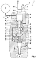
- a fuel injection device 1 according to the invention comprises a pressure booster 2, at least one nozzle needle 3 and a control valve 4. Furthermore, the fuel injection device 1 is provided with a fuel feed 5. The fuel injection device 1 is used for injecting fuel into an injection space 6, which may be a combustion chamber or a mixture formation space, an internal combustion engine, not shown, which may be arranged in particular in a motor vehicle.
- an injection space 6 which may be a combustion chamber or a mixture formation space, an internal combustion engine, not shown, which may be arranged in particular in a motor vehicle.
- the fuel supply 5 comprises a comparatively large-volume high-pressure line 7 in which high-pressure fuel is provided during operation of the fuel injection device 1.
- the high-pressure line 7 is expediently fed with a high-pressure pump.
- a so-called “common rail system” several fuel injectors 1 are connected to one and the same high-pressure line 7.
- the pressure booster 2 comprises a piston rod 8, which is mounted axially adjustable in a corresponding receiving body 9.
- the piston rod 8 is guided in a piston rod guide 10.
- the piston rod 8 has at one end an axial end face 11 with which the piston rod 8 axially delimits a compression space 12.
- the piston rod 8 and the piston 13 may be made in one piece or fixedly connected to each other or axially abut each other loosely. From the compression chamber 12, a compression pressure path 16 leads to at least one spray hole 17, through which the fuel injection into the injection chamber 6 takes place.
- the nozzle needle 3 serves to control the compression pressure path 16. That is, by a stroke of the nozzle needle 3, the compression pressure path 16 can be opened or locked.
- the compression pressure path 16 includes a compression pressure line 18 which connects the compression space 12 with a nozzle chamber 19, which in turn merges into an annular space 20 leading to the at least one injection hole 17.
- a needle seat 21 is formed, with which the nozzle needle 3 cooperates.
- the nozzle chamber 19 and the annular space 20 likewise form components of the compression pressure path 16.
- a pressure stage 22 which initiates a force acting in the opening direction of the nozzle needle 3 force in the nozzle needle 3 at a pressure increase in the nozzle chamber 19.
- a closing compression spring 24 is arranged, which introduces a force acting in the closing direction of the nozzle needle 3 force into the nozzle needle 3 or in a needle assembly 3 comprising the nozzle needle 3.
- the closing compression spring 24 is supported on a needle piston 26, which forms a part of the needle assembly 25.
- the needle piston 26 at one side remote from the at least one injection hole 17 limits the end face and axially a closing pressure chamber 27. The pressure prevailing in the closing pressure chamber 27 generates a force acting in the closing direction on the needle piston 26.
- the nozzle spring chamber 23 is connected via a further throttled connecting line 29 to a filling path 30 which connects the compression chamber 12 with the control chamber 15.
- the closing pressure chamber 27 is also connected via a further throttled connecting line 28 to the filling path 30 or - as here the connection line 29.
- control valve 4 To the control valve 4, three lines are connected, namely a leading to the control chamber 15 control chamber line 31, leading to a working space 14 working space line 32 and a leading to a relatively unpressurized return 33 return line 34.
- first switching position I locks the control valve 4 the Return line 34 and connects the working space line 32 with the control chamber line 31.
- the control chamber 15 is separated from the return 33 and connected to the other with the working space 14.
- the control valve 4 connects in a second switching position II, the control chamber line 31 with the return line 34 and blocks the working space line 32.
- the control chamber 15 is connected on the one hand to the return 33 and on the other hand separated from the working space 14.
- the fuel supply 5 leads the high-pressure fuel of the high-pressure line 7 via a supply line 35, which may be throttled, to the working space 14.
- a return valve 37 is arranged in the filling path 30 or in a leading from the control chamber 15 to the compression chamber 12 filling line, in fact so that it opens to the compression chamber 12 and blocks the control chamber 15 back.
- the return check valve 37 is biased spring loaded as here in its closed position. With the help of the return check valve 37 takes place between the control chamber 15 and the compression chamber 12 only a pressure equalization when in the control chamber 15 relative to the compression chamber 12, an overpressure prevails.
- a pressure compensation path 38 is provided, which - as well as the Befiillungspfad 30 - the compression chamber 12 connects to the control chamber 15.
- the pressure equalization path 38 is controllable by the piston rod 8 and by its axial position for opening and locking, while the filling path 30 is permanently opened independently of the piston rod 8 and of its axial position.
- the pressure equalization path 38 is preferably throttled, which is indicated here by a throttle symbol 39.
- the controllability of the pressure compensation path 38 as a function of the stroke adjustment of the piston rod 8 is expediently designed so that the piston rod in a reproduced in Fig. 1 starting position in which the compression chamber 12 has its largest volume, the pressure equalization path 38 opens. However, as soon as the piston rod 8 carries out a compression stroke for generating the injection pressure in the compression chamber 12, in which case the volume of the compression chamber 12 is reduced, the piston rod 8 blocks the pressure equalization path 38 from a predetermined control stroke.
- the control stroke from which the pressure equalization path 38 is locked, is significantly smaller than the maximum possible compression stroke, the piston rod 8 performs during an injection process.
- the control stroke is less than 50% of the possible compression stroke; however, preferred are smaller control strokes, e.g. less than 10% of the possible compression stroke. It is important that the piston rod 8 already reaches the control stroke during a very small compression stroke, ie, almost immediately after the start of the stroke adjustment, and blocks the pressure compensation path 38.
- the pressure compensation path 38 may have a channel 40 which extends in the receiving body 9 and which opens radially into the compression space 12 through an orifice 41.
- the piston rod 8 can control the pressure equalization path 38 by overflowing the orifice 41 in the region of the control stroke.
- the channel 40 may be designed throttled or contain a throttle point, which is indicated here in each case by the throttle symbol 39.
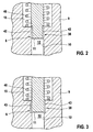
- the pressure equalization path 38 may be formed radially between the piston rod 8 and the piston rod guide 10. It is basically possible to form the pressure equalization path 38 with at least one axial groove 42, which is formed in the piston rod 8. Suitably, a plurality of such rod axial grooves 42 are provided, which are arranged circumferentially distributed on the piston rod 8. Each rod-axial groove 42 is axially open to the compression chamber 12 and extends at open pressure equalization path 38, ie at their starting position arranged piston rod 8 to the control chamber 15. When locked pressure equalization path 38, so when reaching the control stroke, the rod axial grooves 42 are radially outward closed by the piston rod guide 10.
- the pressure equalization path according to FIG. 3 can have at least one axial groove 43, which is formed in the piston rod guide 10.
- a plurality of such guide axial grooves 43 are provided, which then advantageous arranged distributed circumferentially.
- the arrangement and dimensioning of the guide axial grooves 43 takes place so that they are axially open to the control chamber 15.
- the guide axial grooves 43 extend with the pressure equalization path 38 open, that is to say in the starting position of the piston rod 8, as far as the compression space 12, so that they communicate with it.
- the guide Axialnuten 43 are closed by the piston rod 8 radially inward.
- the dimensioning of the axial grooves 42 and 43 is preferably such that the pressure equalization path 38 is throttled when open.
- the pressure compensation path 38 can also be equipped with a channel 44 which extends in the piston rod 8.
- this channel 44 is connected to the control chamber 15 through an orifice 45.
- the positioning of this orifice 45 is chosen so that the piston rod 8 extends axially with the mouth opening 44 formed therefrom from the control chamber 15 to block the pressure equalization path 38.
- the mouth opening 45 is thus run over by the compression stroke of the piston rod guide 10 and thereby closed.
- this channel 44 may be configured throttled or contain a corresponding throttle point.
- the pressure equalization path 38 can in principle also be formed by a correspondingly dimensioned radial clearance between the piston rod 8 and the piston rod guide 10.
- the fuel injection device 1 operates as follows:
- the control valve 4 is transferred to its second switching position II. As a result, it comes in the control chamber 15 to a pressure drop. This results in a resultant force on the piston rod 8, which drives the piston rod 8 to carry out a compression stroke. During this compression stroke, the volume of the compression chamber 12 is reduced, whereby therein the desired pressure transmission takes place in order to achieve the respectively desired injection pressure. Furthermore, when the control stroke is reached, the pressure compensation path 38 is blocked. At the same time a return spring 46 is tensioned by the axial adjustment of the piston rod 8, which is supported in the control chamber 15 on the piston rod 8 directly or indirectly via a collar 47.
- the control valve 4 is switched back to its first switching position I.
- the pressure increases again, which, supported by the return spring 46, drives the piston rod 8 back into its starting position.
- the volume in the compression chamber 12 is increased again.
- the associated pressure drop propagates via the compression pressure path 16 into the nozzle chamber 19.
- the pressure drop in the nozzle chamber 19 in conjunction with the intermediate increased pressure in the closing pressure chamber 27 and supported by the closing pressure spring 24 is then carried out closing the nozzle needle 3, which ends the injection process.
- the compression chamber 12 is nachgefiillt via the filling path 30, essentially with the high pressure.
- the compression chamber 12 can again follow the pressure curve in the high-pressure line 7.
Landscapes
- Engineering & Computer Science (AREA)
- Chemical & Material Sciences (AREA)
- Combustion & Propulsion (AREA)
- Mechanical Engineering (AREA)
- General Engineering & Computer Science (AREA)
- Fuel-Injection Apparatus (AREA)
Abstract
Description
- Die Erfindung betrifft eine Kraftstoffeinspritzeinrichtung für eine Brennkraftmaschine, insbesondere in einem Kraftfahrzeug, mit den Merkmalen des Oberbegriffs des Anspruchs 1.
- Eine derartige Kraftstoffeinspritzeinrichtung ist beispielsweise aus der DE 102 29 418 A1 bekannt und umfasst einen Druckübersetzer, eine Düsennadel, ein Steuerventil, eine Kraftstoffzuführung und einen Befiillungspfad. Der Druckübersetzer weist eine axial verstellbare Kolbenstange auf, die stirnseitig einen Kompressionsraum axial begrenzt und einen Kolben trägt, der einen Arbeitsraum von einem Steuerraum trennt. Mit der Düsennadel ist ein vom Kompressionsraum zu wenigstens einem Spritzloch führender Kompressionsdruckpfad zum Öffnen und Sperren steuerbar. Das Steuerventil verbindet in einer ersten Schaltstellung den Steuerraum mit dem Arbeitsraum und trennt den Steuerraum von einem Rücklauf. In einer zweiten Schaltstellung trennt das Steuerventil den Steuerraum vom Arbeitsraum und verbindet den Steuerraum mit dem Rücklauf. Die Kraftstoffzuführung kann im Betrieb der Kraftstoffeinspritzeinrichtung unter Hochdruck stehenden Kraftstoff dem Arbeitsraum zuführen. Der Steuerraum ist über den Befüllungspfad mit dem Kompressionsraum verbunden.
- Bei der bekannten Kraftstoffeinspritzeinrichtung führt der Befüllungspfad durch einen Düsenfederraum und umfasst einen vom Düsenfederraum zum Kompressionsraum führenden gedrosselten ersten Verbindungskanal sowie einen vom Düsenfederraum zum Steuerraum führenden gedrosselten zweiten Verbindungskanal. Im Betrieb der Kraftstoffeinspritzeinrichtung herrscht in einem Ausgangszustand im Kompressionsraum der von der Kraftstoffzuführung bereitgestellte Hochdruck. Zur Durchführung einer Kraftstoffeinspritzung wird die Kolbenstange zur Durchführung eines Kompressionshubs angesteuert. Durch den Kompressionshub kommt es im Kompressionsraum zu einer zusätzlichen Verdichtung, was den Druck im Kompressionsraum auf den gewünschten Einspritzdruck erhöht. Über den Kompressionsdruckpfad steht dieser Einspritzdruck dann an dem wenigsten einen Spritzloch zur Einspritzung bereit und kann durch Öffnen der Düsennadel in den jeweiligen Brennraum eingespritzt werden. Nach einem solchen Einspritzvorgang muss die Kolbenstange wieder in ihre Ausgangsstellung zurückverstellt werden. Damit dies möglich ist, muss der Kompressionsraum wieder mit Kraftstoff befüllt werden, was über den gedrosselten Befiillungspfad erfolgt. Während des Kompressionshubs kann außerdem Kraftstoff aus dem Kompressionsraum in den Befüllungspfad entweichen, was zu einem unerwünschten Druckabfall führt bzw. was die Höhe des erreichbaren Einspritzdrucks reduziert.
- Die erfmdungsgemäße Kraftstoffeinspritzeinrichtung mit den Merkmalen des Anspruchs 1 hat dem gegenüber den Vorteil, dass im Kompressionsraum während des Kompressionshubs im wesentlichen kein Druckverlust entsteht, wodurch insgesamt ein höherer Einspritzdruck erzielt werden kann. Erreicht wird dies bei der Erfmdung dadurch, dass zum einen im Befiillungspfad ein Rücklaufsperrventil angeordnet ist, das ein Abströmen von Kraftstoff aus dem Kompressionsraum durch den Befiillungspfad verhindert, und dass zum anderen zusätzlich ein Druckausgleichspfad vorgesehen ist, der ebenfalls den Steuerraum mit dem Kompressionsraum verbindet und mit Hilfe der Kolbenstange zum Öffnen und Sperren gesteuert werden kann. Auf diese Weise kann die Kolbenstange einen Hub durchführen, während dem auch der Druckausgleichspfad gesperrt ist, so dass der Kraftstoff aus dem Kompressionsraum im wesentlichen ausschließlich durch den Kompressionsdruckpfad entweichen kann. Wesentlich ist, dass der Druckausgleichspfad in der Ausgangsstellung der Kolbenstange geöffnet ist, wodurch permanent ein Druckausgleich zwischen dem Kompressionsraum und dem Steuerraum stattfinden kann. Da außerdem in der ersten Schaltstellung des Steuerventils der Steuerraum mit dem Arbeitsraum kommuniziert, fmdet auch zwischen Steuerraum und Arbeitsraum ein Druckausgleich statt. Auf diese Weise stellt sich der in der Kraftstoffzuführung bereitgestellte Hochdruck automatisch auch im Arbeitsraum, im Steuerraum und im Kompressionsraum ein. Dies ist besonders wichtig für Kraftstoffeinspritzeinrichtungen, bei denen der in der Kraftstoffzuführung bereitgestellte Hochdruck variiert werden kann. Durch die Variation des Hochdrucks lässt sich der mit Hilfe des Druckübersetzers erzielbare Einspritzdruck variieren, was eine verbesserte Adaption des Einspritzvorgangs an den aktuellen Betriebszustand der jeweiligen Brennkraftmaschine ermöglicht, um dadurch Emissionen zu reduzieren und die Leistung und/oder den Wirkungsgrad der Brennkraftmaschine zu erhöhen. Für den Fall, dass zwischen zwei Einspritzvorgängen der in der Kraftstoffzuführung bereitgestellt Hochdruck geändert wird, muss der Druck im Kompressionsraum dieser Druckänderung folgen können, damit beim nächsten Einspritzvorgang der gewünschte Einspritzdruck erreicht wird. Ohne den vorgeschlagenen Druckausgleichspfad wäre ein Druckausgleich im Kompressionsraum über den mit dem Rücklaufsperrventil versehenen Befiillungspfad nur bei einer Druckerhöhung in der Kraftstoffzuführung möglich, jedoch nicht bei einer Druckabsenkung in der Kraftstoffzuführung, da in dieser Richtung das Rücklaufsperrventil sperrt. Durch den erfindungsgemäß vorgesehenen Druckausgleichspfad ist jedoch zumindest in der Ausgangsstellung der Kolbenstange der gewünschte Druckausgleich möglich. Auf diese Weise arbeitet der Druckübersetzer besonders präzise und kann Druckänderungen in der Kraftstoffzuführung rasch folgen.
- Gemäß einer besonders vorteilhaften Ausführungsform kann der Druckausgleichspfad gedrosselt ausgestaltet sein. Diese Bauweise hat zur Folge, dass zum einen Druckimpulse, die sich im Hydrauliksystem ausbreiten können, nicht oder nur stark gedämpft in den Kompressionsraum gelangen. Zum anderen wird dadurch erreicht, dass der Druckanstieg im Kompressionsraum bei einem Kompressionshub der Kolbenstange bis zu dem Zeitpunkt, zu dem die Kolbenstange den Druckausgleichspfad zum Sperren ansteuert, nicht oder nur geringfiigig behindert wird.
- Weitere wichtige Merkmale und Vorteile der erfmdungsgemäßen Kraftstoffeinspritzeinrichtung ergeben sich aus den Unteransprüchen, aus den Zeichnungen und aus der zugehörigen Figurenbeschreibung anhand der Zeichnungen.
- Ausführungsbeispiele der erfindungsgemäßen Kraftstoffeinspritzeinrichtung sind in den Zeichnungen dargestellt und werden im folgenden näher erläutert, wobei sich gleiche Bezugszeichen auf gleiche oder ähnliche oder funktional gleiche Komponenten beziehen.
- Es zeigen, jeweils schematisch,
- Fig. 1
- eine schaltplanartige Prinzipdarstellung einer Kraftstoffeinspritzeinrichtung nach der Erfindung,
- Fig. 2 bis 4
- vergrößerte Ansichten auf ein Detail II in Fig. 1, jedoch bei unterschiedlichen Ausführungsformen.
- Entsprechend Fig. 1 umfasst eine Kraftstoffeinspritzeinrichtung 1 nach der Erfmdung einen Druckübersetzer 2, wenigstens eine Düsennadel 3 sowie ein Steuerventil 4. Des weiteren ist die Kraftstoffeinspritzeinrichtung 1 mit einer Kraftstoffzuführung 5 versehen. Die Kraftstoffeinspritzeinrichtung 1 dient zum Einspritzen von Kraftstoff in einen Einspritzraum 6, der ein Brennraum oder ein Gemischbildungsraum sein kann, einer nicht gezeigten Brennkraftmaschine, die insbesondere in einem Kraftfahrzeug angeordnet sein kann.
- Die Kraftstoffzuführung 5 umfasst eine vergleichsweise großvolumige Hochdruckleitung 7, in der im Betrieb der Kraftstoffeinspritzeinrichtung 1 unter Hochdruck stehender Kraftstoff bereitgestellt wird. Gespeist wird die Hochdruckleitung 7 zweckmäßig mit einer Hochdruckpumpe. Bei einem sogenannten "Common-Rail-System" sind mehrere Kraftstoffeinspritzeinrichtungen 1 an ein und dieselbe Hochdruckleitung 7 angeschlossen.
- Der Druckübersetzer 2 umfasst eine Kolbenstange 8, die axial verstellbar in einem entsprechenden Aufnahmekörper 9 gelagert ist. Dabei ist die Kolbenstange 8 in einer Kolbenstangenführung 10 gefiihrt. Die Kolbenstange 8 besitzt an einem Ende eine axiale Stirnseite 11, mit der die Kolbenstange 8 einen Kompressionsraum 12 axial begrenzt. Beabstandet vom Kompressionsraum 12, z.B. am entgegengesetzten Ende, trägt die Kolbenstange 8 einen Kolben 13, der im Aufnahmekörper 9 einen Arbeitsraum 14 von einem Steuerraum 15 trennt. Die Kolbenstange 8 und der Kolben 13 können einstückig hergestellt sein oder fest miteinander verbunden sein oder axial lose aneinander anliegen. Vom Kompressionsraum 12 führt ein Kompressionsdruckpfad 16 zu wenigstens einem Spritzloch 17, durch das die Kraftstoffeinspritzung in den Einspritzraum 6 erfolgt. Die Düsennadel 3 dient zum Steuern des Kompressionsdruckpfads 16. Das heißt, durch einen Hub der Düsennadel 3 kann der Kompressionsdruckpfad 16 geöffnet bzw. gesperrt werden. Der Kompressionsdruckpfad 16 umfasst eine Kompressionsdruckleitung 18, die den Kompressionsraum 12 mit einem Düsenraum 19 verbindet, der seinerseits in einen zu dem wenigstens einen Spritzloch 17 führenden Ringraum 20 übergeht. Unmittelbar stromauf des wenigstens einen Spritzlochs 17 ist ein Nadelsitz 21 ausgebildet, mit dem die Düsennadel 3 zusammenwirkt. Der Düsenraum 19 und der Ringraum 20 bilden dabei ebenfalls Bestandteile des Kompressionsdruckpfads 16.
- Im Düsenraum 19 weist die Düsennadel 3 eine Druckstufe 22 auf, die bei einer Druckerhöhung im Düsenraum 19 eine in Öffnungsrichtung der Düsennadel 3 wirkende Kraft in die Düsennadel 3 einleitet. In einem Düsenfederraum 23 ist eine Schließdruckfeder 24 angeordnet, die in die Düsennadel 3 bzw. in einen die Düsennadel 3 umfassenden Nadelverband 25 eine in Schließrichtung der Düsennadel 3 wirkende Kraft einleitet. Im hier gezeigten Ausführungsbeispiel ist die Schließdruckfeder 24 an einem Nadelkolben 26 abgestützt, der einen Bestandteil des Nadelverbands 25 bildet. Des weiteren begrenzt der Nadelkolben 26 an einer von dem wenigstens einen Spritzloch 17 abgewandten Seite stirnseitig und axial einen Schließdruckraum 27. Der im Schließdruckraum 27 herrschende Druck erzeugt am Nadelkolben 26 eine in Schließrichtung wirksame Kraft.
- Der Düsenfederraum 23 ist über eine weitere gedrosselte Verbindungsleitung 29 an einen Befüllungspfad 30 angeschlossen, der den Kompressionsraum 12 mit dem Steuerraum 15 verbindet. Der Schließdruckraum 27 ist über eine weitere gedrosselte Verbindungsleitung 28 ebenfalls an den Befüllungspfad 30 oder - wie hier- an die Verbindungsleitung 29 angeschlossen.
- An das Steuerventil 4 sind drei Leitungen angeschlossen, nämlich eine zum Steuerraum 15 führende Steuerraumleitung 31, eine zum Arbeitsraum 14 führende Arbeitsraumleitung 32 und eine zu einem relativ drucklosen Rücklauf 33 führende Rücklaufleitung 34. In einer in Fig. 1 wiedergegebenen ersten Schaltstellung I sperrt das Steuerventil 4 die Rücklaufleitung 34 und verbindet die Arbeitsraumleitung 32 mit der Steuerraumleitung 31. Hierdurch ist der Steuerraum 15 zum einen vom Rücklauf 33 getrennt und zum anderen mit dem Arbeitsraum 14 verbunden. Im Unterschied dazu verbindet das Steuerventil 4 in einer zweiten Schaltstellung II die Steuerraumleitung 31 mit der Rücklaufleitung 34 und sperrt die Arbeitsraumleitung 32. Dadurch ist der Steuerraum 15 einerseits mit dem Rücklauf 33 verbunden und andererseits vom Arbeitsraum 14 getrennt.
- Die Kraftstoffzuführung 5 führt den unter Hochdruck stehenden Kraftstoff der Hochdruckleitung 7 über eine Zuführungsleitung 35, die gegebenenfalls gedrosselt sein kann, dem Arbeitsraum 14 zu.
- Bei der erfmdungsgemäßen Kraftstoffeinspritzeinrichtung 1 ist im Befüllungspfad 30 bzw. in einer vom Steuerraum 15 zum Kompressionsraum 12 führenden Befüllungsleitung 36 ein Rücklaufsperrventil 37 angeordnet, um zwar so, dass es zum Kompressionsraum 12 hin öffnet und zum Steuerraum 15 hin sperrt. Vorzugsweise ist das Rücklaufsperrventil 37 wie hier in seine Schließstellung federbelastet vorgespannt. Mit Hilfe des Rücklaufsperrventils 37 erfolgt zwischen Steuerraum 15 und Kompressionsraum 12 nur dann ein Druckausgleich, wenn im Steuerraum 15 relativ zum Kompressionsraum 12 ein Überdruck herrscht.
- Des weiteren ist ein Druckausgleichspfad 38 vorgesehen, der - ebenso wie der Befiillungspfad 30 - den Kompressionsraum 12 mit dem Steuerraum 15 verbindet. Allerdings ist der Druckausgleichspfad 38 durch die Kolbenstange 8 bzw. durch deren Axialstellung zum Öffnen und Sperren steuerbar, während der Befüllungspfad 30 unabhängig von der Kolbenstange 8 bzw. von deren Axialstellung permanent geöffnet ist. Der Druckausgleichspfad 38 ist vorzugsweise gedrosselt, was hier durch ein Drosselsymbol 39 angedeutet ist.
- Die Steuerbarkeit des Druckausgleichspfad 38 in Abhängigkeit der Hubverstellung der Kolbenstange 8 ist zweckmäßig so ausgestaltet, dass die Kolbenstange in einer in Fig. 1 wiedergegebenen Ausgangsstellung, in welcher der Kompressionsraum 12 sein größtes Volumen aufweist, den Druckausgleichspfad 38 öffnet. Sobald jedoch die Kolbenstange 8 zur Erzeugung des Einspritzdrucks im Kompressionsraum 12 einen Kompressionshub durchführt, bei dem in der Folge das Volumen des Kompressionsraums 12 reduziert wird, sperrt die Kolbenstange 8 ab einem vorbestimmten Steuerhub den Druckausgleichspfad 38.
- Dadurch ergibt sich eine Zwangssteuerung des Druckausgleichspfads 38 durch die Kolbenstange 8. Der Steuerhub, ab dem der Druckausgleichspfad 38 gesperrt ist, ist dabei deutlich kleiner als der maximal mögliche Kompressionshub, den die Kolbenstange 8 während eines Einspritzvorgangs durchführt. Zweckmäßig beträgt der Steuerhub weniger als 50 % des möglichen Kompressionshubs; bevorzugt werden jedoch kleinere Steuerhübe, die z.B. kleiner als 10 % des möglichen Kompressionshubs sind. Wichtig ist, dass die Kolbenstange 8 bereits bei einem sehr kleinen Kompressionshub, also quasi unmittelbar nach Beginn der Hubverstellung, den Steuerhub erreicht und den Druckausgleichspfad 38 sperrt.
- Im folgenden werden unterschiedliche Ausführungsformen für die Ausgestaltungen des Druckausgleichspfads 38 wiedergegeben, wobei es durchaus möglich ist, die einzelnen Varianten auf geeignete Weise miteinander zu kombinieren.
- Entsprechend Fig. 1 kann der Druckausgleichspfad 38 einen Kanal 40 aufweisen, der im Aufnahmekörper 9 verläuft und der durch eine Mündungsöffnung 41 radial in den Kompressionsraum 12 einmündet. Bei dieser Ausführungsform kann die Kolbenstange 8 den Druckausgleichspfad 38 dadurch steuern, dass sie die Mündungsöffnung 41 im Bereich des Steuerhubs überfährt. Der Kanal 40 kann gedrosselt ausgestaltet sein oder eine Drosselstelle enthalten, was hier jeweils durch das Drosselsymbol 39 angedeutet ist.
- Entsprechend Fig. 2 und 3 kann der Druckausgleichspfad 38 radial zwischen der Kolbenstange 8 und der Kolbenstangenführung 10 ausgebildet sein. Dabei ist es grundsätzlich möglich, den Druckausgleichspfad 38 mit wenigstens einer Axialnut 42 auszubilden, die in der Kolbenstange 8 ausgebildet ist. Zweckmäßig sind mehrere solcher Stangen-Axialnuten 42 vorgesehen, die umfangsmäßig verteilt an der Kolbenstange 8 angeordnet sind. Jede Stangen-Axialnut 42 ist axial zum Kompressionsraum 12 offen und erstreckt sich bei geöffnetem Druckausgleichspfad 38, also bei in ihrer Ausgangsstellung angeordneter Kolbenstange 8 bis zum Steuerraum 15. Bei gesperrtem Druckausgleichspfad 38, also bei Erreichen des Steuerhubs sind die Stangen-Axialnuten 42 radial außen von der Kolbenstangenführung 10 verschlossen.
- Zusätzlich oder alternativ kann der Druckausgleichspfad gemäß Fig. 3 zumindest eine Axialnut 43 aufweisen, die in der Kolbenstangenführung 10 ausgebildet ist. Zweckmäßig sind mehrere derartige Führungs-Axialnuten 43 vorgesehen, die dann vorteilhaft umfangsmäßig verteilt angeordnet sind. Die Anordnung und Dimensionierung der Führungs-Axialnuten 43 erfolgt dabei so, dass sie axial zum Steuerraum 15 hin offen sind. Des weiteren erstrecken sich die Führungs-Axialnuten 43 bei geöffnetem Druckausgleichspfad 38, also in der Ausgangsstellung der Kolbenstange 8 bis zum Kompressionsraum 12, so dass sie mit diesem kommunizieren. Bei Erreichen des Steuerhubs, also bei gesperrtem Druckausgleichspfad 38 sind die Führungs-Axialnuten 43 von der Kolbenstange 8 radial innen verschlossen.
- Des weiteren erfolgt die Dimensionierung der Axialnuten 42 und 43 vorzugsweise so, dass der Druckausgleichspfad 38 bei geöffnetem Zustand gedrosselt ist.
- Entsprechend Fig. 4 kann der Druckausgleichspfad 38 auch mit einem Kanal 44 ausgestattet sein, der sich in der Kolbenstange 8 erstreckt. Bei geöffnetem Druckausgleichspfad 38 ist dieser Kanal 44 durch eine Mündungsöffnung 45 mit dem Steuerraum 15 verbunden. Die Positionierung dieser Mündungsöffnung 45 ist dabei so gewählt, dass die Kolbenstange 8 mit der daran ausgebildeten Mündungsöffnung 44 aus dem Steuerraum 15 axial ausfährt, um den Druckausgleichspfad 38 zu sperren. Die Mündungsöffnung 45 wird somit durch den Kompressionshub von der Kolbenstangenführung 10 überfahren und dadurch geschlossen. Auch dieser Kanal 44 kann gedrosselt ausgestaltet sein oder eine entsprechende Drosselstelle enthalten.
- Bei einer weiteren, hier nicht dargestellten Ausführungsform kann der Druckausgleichspfad 38 grundsätzlich auch durch ein entsprechend dimensioniertes Radialspiel zwischen der Kolbenstange 8 und der Kolbenstangenführung 10 ausgebildet sein.
- In dem in Fig. 1 gezeigten Ausgangszustand herrscht in der Hochdruckleitung 7 ein vorbestimmter Hochdruck, das Steuerventil 4 nimmt seine erste Schaltstellung I ein, die Kolbenstange 8 befindet sich in ihrer Ausgangsstellung und die Düsennadel 3 sitzt in ihrem Nadelsitz 21. Der in der Hochdruckleitung 7 herrschende Hochdruck kann sich im kommunizierenden System ausbreiten und herrscht in der Folge auch im Arbeitsraum 14, im Steuerraum 15, im Kompressionsraum 12, im Schließdruckraum 27 und im Düsenfederraum 23 ebenso wie im Düsenraum 19. Eine Druckänderung in der Hochdruckleitung 7 wirkt sich somit im gesamten kommunizierenden System aus, insbesondere kann durch den in der Ausgangsstellung der Kolbenstange 8 geöffneten Druckausgleichspfad 38 auch der Kompressionsraum 12 einer Druckänderung in der Hochdruckleitung 7 folgen.
- Zum Starten und Durchführen eines Einspritzvorgangs wird das Steuerventil 4 in seine zweite Schaltstellung II überführt. In der Folge kommt es im Steuerraum 15 zu einem Druckabfall. Hierdurch entsteht an der Kolbenstange 8 eine resultierende Kraft, welche die Kolbenstange 8 zur Durchführung eines Kompressionshubs antreibt. Während dieses Kompressionshubs wird das Volumen des Kompressionsraums 12 verkleinert, wodurch darin die gewünschte Druckübersetzung zur Erzielung des jeweils erwünschten Einspritzdrucks erfolgt. Des weiteren wird bei Erreichen des Steuerhubs der Druckausgleichspfad 38 gesperrt. Gleichzeitig wird durch die Axialverstellung der Kolbenstange 8 eine Rückstellfeder 46 gespannt, die sich im Steuerraum 15 an der Kolbenstange 8 direkt oder indirekt über einen Bund 47 abstützt. Da der Druckausgleichspfad 38 gesperrt ist und in dieser Richtung das Rücklaufsperrventil 37 den Befiillungspfad 30 sperrt, pflanzt sich der im Kompressionsraum 12 ansteigende Druck über den Kompressionsdruckpfad 16 bis in den Düsenraum 19 fort. Bei Erreichen des gewünschten Einspritzdrucks bewirkt dieser über die Druckstufe 22 das Öffnen der Düsennadel 3, so dass dann die Kraftstoffeinspritzung durch das wenigstens eine Spritzloch 17 mit dem Einspritzdruck erfolgt.
- Zum Beenden des Einspritzvorgangs wird das Steuerventil 4 wieder in seine erste Schaltstellung I geschaltet. In der Folge steigt im Steuerraum 15 wieder der Druck an, was die Kolbenstange 8 unterstützt durch die Rückstellfeder 46 in ihre Ausgangsstellung zurück antreibt. Hierdurch wird das Volumen im Kompressionsraum 12 wieder vergrößert. Der damit einhergehende Druckabfall pflanzt sich über den Kompressionsdruckpfad 16 in den Düsenraum 19 fort. Der Druckabfall im Düsenraum 19 in Verbindung mit dem zwischenzeitlich erhöhten Druck im Schließdruckraum 27 und unterstützt durch die Schließdruckfeder 24 erfolgt dann das Schließen der Düsennadel 3, was den Einspritzvorgang beendet. Gleichzeitig wird dabei der Kompressionsraum 12 über den Befüllungspfad 30 nachgefiillt, im wesentlichen mit dem Hochdruck. Sobald die Kolbenstange 8 den Druckausgleichspfad 38 wieder freigibt, kann der Kompressionsraum 12 wieder dem Druckverlauf in der Hochdruckleitung 7 folgen.
-
- 1
- Kraftstoffeinspritzeinrichtung
- 2
- Druckübersetzer
- 3
- Düsennadel
- 4
- Steuerventil
- 5
- Kraftstoffzuführung
- 6
- Einspritzraum
- 7
- Hochdruckleitung
- 8
- Kolbenstange
- 9
- Aufnahmekörper
- 10
- Kolbenstangenführung
- 11
- Stirnseite von 8
- 12
- Kompressionsraum
- 13
- Kolben
- 14
- Arbeitsraum
- 15
- Steuerraum
- 16
- Kompressionsdruckpfad
- 17
- Spritzloch
- 18
- Kompressionsdruckleitung
- 19
- Düsenraum
- 20
- Ringraum
- 21
- Nadelsitz
- 22
- Druckstufe
- 23
- Düsenfederraum
- 24
- Schließdruckfeder
- 25
- Nadelverband
- 26
- Nadelkolben
- 27
- Schließdruckraum
- 28
- Verbindungsleitung
- 29
- Verbindungsleitung
- 30
- Befiillungspfad
- 31
- Steuerraumleitung
- 32
- Arbeitsraumleitung
- 33
- Rücklauf
- 34
- Rücklaufleitung
- 35
- Zuführungsleitung
- 36
- Befüllungsleitung
- 37
- Rücklaufsperrventil
- 38
- Druckausgleichspfad
- 39
- Drossel
- 40
- Kanal
- 41
- Mündung von 40
- 42
- Axialnut in 8
- 43
- Axialnut in 10
- 44
- Kanal
- 45
- Mündung von 44
- 46
- Rückstellfeder
- 47
- Bund
Claims (12)
- Kraftstoffeinspritzeinrichtung für eine Brennkraftmaschine, insbesondere in einem Kraftfahrzeug,- mit einem Druckübersetzer (2), der eine axial verstellbare Kolbenstange (8) aufweist, die stirnseitig einen Kompressionsraum (12) axial begrenzt und einen Kolben (13) trägt, der einen Arbeitsraum (14) von einem Steuerraum (15) trennt,- mit wenigstens einer Düsennadel (3), mit der ein vom Kompressionsraum (12) zu wenigstens einem Spritzloch (17) führender Kompressionsdruckpfad (16) zum Öffnen und Sperren steuerbar ist,- mit einem Steuerventil (4), das in einer ersten Schaltstellung den Steuerraum (15) mit dem Arbeitsraum (14) verbindet und den Steuerraum (15) von einem Rücklauf (33) trennt und das in einer zweiten Schaltstellung den Steuerraum (15) vom Arbeitsraum (14) trennt und den Steuerraum (15) mit dem Rücklauf (33) verbindet,- mit einer Kraftstoffzuführung (5), die im Betrieb der Kraftstoffeinspritzeinrichtung (1) unter Hochdruck stehenden Kraftstoff dem Arbeitsraum (14) zuführt,- mit einem Befüllungspfad (30), der den Kompressionsraum (12) mit dem Steuerraum (15) verbindet,dadurch gekennzeichnet,- dass im Befüllungspfad (30) ein Rücklaufsperrventil (37) angeordnet ist, das zum Kompressionsraum (12) hin öffnet und zum Steuerraum (15) hin sperrt,- dass ein Druckausgleichspfad (38) vorgesehen ist, der den Steuerraum (15) mit dem Kompressionsraum (12) verbindet,- dass die Kolbenstange (8) in Abhängigkeit ihrer Axialstellung den Druckausgleichspfad (38) zum Öffnen und Sperren steuert.
- Kraftstoffeinspritzeinrichtung nach Anspruch 1,
dadurch gekennzeichnet,
dass der Druckausgleichspfad (38) gedrosselt ist. - Kraftstoffeinspritzeinrichtung nach Anspruch 1 oder 2,
dadurch gekennzeichnet,
dass die Kolbenstange (8) in einer Ausgangsstellung, in welcher der Kompressionsraum (12) sein größtes Volumen aufweist, den Druckausgleichspfad (38) öffnet und bei einem Kompressionshub, bei dem das Volumen des Kompressionsraum (12) reduziert wird, ab einem vorbestimmten Steuerhub den Druckausgleichspfad (38) sperrt. - Kraftstoffeinspritzeinrichtung nach Anspruch 3,
dadurch gekennzeichnet,
dass der Steuerhub weniger als 50 % oder weniger als 40 % oder weniger als 30% oder weniger als 20 % oder weniger als 10 % des möglichen Kompressionshubs beträgt. - Kraftstoffeinspritzeinrichtung nach einem der Ansprüche 1 bis 4,
dadurch gekennzeichnet,- dass der Druckausgleichspfad (38) mit einem Kanal (40) durch eine Mündungsöffnung (41) radial in den Kompressionsraum (12) einmündet,- dass die Kolbenstange (8) zum Steuern des Druckausgleichspfads (38) die Mündungsöffnung (41) überfährt. - Kraftstoffeinspritzeinrichtung nach einem der Ansprüche 1 bis 4,
dadurch gekennzeichnet,- dass der Druckausgleichspfad (38) einen Kanal (44) aufweist, der sich in der Kolbenstange (8) erstreckt und bei geöffnetem Druckausgleichspfad (38) durch eine Mündungsöffnung (45) radial mit dem Steuerraum (15) verbunden ist,- dass die Kolbenstange (8) zum Steuern des Druckausgleichspfads mit der Mündungsöffnung (45) aus dem Steuerraum (15) ausfährt. - Kraftstoffeinspritzeinrichtung nach Anspruch 2 sowie nach Anspruch 5 oder 6,
dadurch gekennzeichnet,
dass der Kanal (40; 44) gedrosselt ausgestaltet ist oder eine Drosselstelle enthält. - Kraftstoffeinspritzeinrichtung nach einem der Ansprüche 1 bis 4,
dadurch gekennzeichnet,
dass der Druckausgleichspfad (38) radial zwischen der Kolbenstange (8) und einer Kolbenstangenführung (10) ausgebildet ist. - Kraftstoffeinspritzeinrichtung nach Anspruch 8,
dadurch gekennzeichnet,
dass der Druckausgleichspfad (38) wenigstens eine Axialnut (42) aufweist, die in der Kolbenstange (8) ausgebildet ist, die axial zum Kompressionsraum (12) offen ist, die sich bei geöffnetem Druckausgleichspfad (38) bis zum Steuerraum (15) erstreckt und die bei gesperrtem Druckausgleichspfad (38) von der Kolbenstangenführung (10) radial außen verschlossen ist. - Kraftstoffeinspritzeinrichtung nach Anspruch 8 oder 9,
dadurch gekennzeichnet,
dass der Druckausgleichspfad (38) wenigstens eine Axialnut (43) aufweist, die in der Kolbenstangenführung (10) ausgebildet ist, die axial zum Steuerraum (15) offen ist, die sich bei geöffnetem Druckausgleichspfad (38) bis zum Kompressionsraum (12) erstreckt und die bei gesperrtem Druckausgleichspfad (38) von der Kolbenstange (8) radial innen verschlossen ist. - Kraftstoffeinspritzeinrichtung nach Anspruch 9 oder 10,
dadurch gekennzeichnet,
dass mehrere Axialnuten (42, 43) vorgesehen sind, die umfangsmäßig verteilt angeordnet sind. - Kraftstoffeinspritzeinrichtung nach einem der Ansprüche 1 bis 4,
dadurch gekennzeichnet,
dass der Druckausgleichspfad (38) durch ein Radialspiel zwischen der Kolbenstange (8) und einer Kolbenstangenführung (10) ausgebildet ist.
Applications Claiming Priority (1)
| Application Number | Priority Date | Filing Date | Title |
|---|---|---|---|
| DE200410053269 DE102004053269A1 (de) | 2004-11-04 | 2004-11-04 | Kraftstoffeinspritzeinrichtung |
Publications (2)
| Publication Number | Publication Date |
|---|---|
| EP1655479A1 true EP1655479A1 (de) | 2006-05-10 |
| EP1655479B1 EP1655479B1 (de) | 2007-08-08 |
Family
ID=35207566
Family Applications (1)
| Application Number | Title | Priority Date | Filing Date |
|---|---|---|---|
| EP05109675A Expired - Lifetime EP1655479B1 (de) | 2004-11-04 | 2005-10-18 | Kraftstoffeinspritzeinrichtung |
Country Status (3)
| Country | Link |
|---|---|
| EP (1) | EP1655479B1 (de) |
| DE (2) | DE102004053269A1 (de) |
| ES (1) | ES2288728T3 (de) |
Families Citing this family (1)
| Publication number | Priority date | Publication date | Assignee | Title |
|---|---|---|---|---|
| US7942525B2 (en) | 2009-07-09 | 2011-05-17 | Nike, Inc. | Contrast sensitivity testing and/or training using circular contrast zones |
Citations (5)
| Publication number | Priority date | Publication date | Assignee | Title |
|---|---|---|---|---|
| US4069800A (en) * | 1975-01-24 | 1978-01-24 | Diesel Kiki Co., Ltd. | Fuel injection apparatus |
| DE10229417A1 (de) * | 2002-06-29 | 2004-01-15 | Robert Bosch Gmbh | Speichereinspritzsystem mit Variodüse und Druckübersetzungseinrichtung |
| DE10229418A1 (de) | 2002-06-29 | 2004-01-29 | Robert Bosch Gmbh | Einrichtung zur Dämpfung des Nadelhubes an Kraftstoffinjektoren |
| DE10247210A1 (de) * | 2002-10-10 | 2004-04-22 | Robert Bosch Gmbh | Filteranordnung für Kraftstoffeinspritzsysteme |
| DE10248467A1 (de) * | 2002-10-17 | 2004-05-06 | Robert Bosch Gmbh | Kraftstoffeinspritzeinrichtung mit Druckübersetzer und fördermengenreduziertem Niederdruckkreis |
-
2004
- 2004-11-04 DE DE200410053269 patent/DE102004053269A1/de not_active Withdrawn
-
2005
- 2005-10-18 ES ES05109675T patent/ES2288728T3/es not_active Expired - Lifetime
- 2005-10-18 DE DE200550001174 patent/DE502005001174D1/de not_active Expired - Fee Related
- 2005-10-18 EP EP05109675A patent/EP1655479B1/de not_active Expired - Lifetime
Patent Citations (5)
| Publication number | Priority date | Publication date | Assignee | Title |
|---|---|---|---|---|
| US4069800A (en) * | 1975-01-24 | 1978-01-24 | Diesel Kiki Co., Ltd. | Fuel injection apparatus |
| DE10229417A1 (de) * | 2002-06-29 | 2004-01-15 | Robert Bosch Gmbh | Speichereinspritzsystem mit Variodüse und Druckübersetzungseinrichtung |
| DE10229418A1 (de) | 2002-06-29 | 2004-01-29 | Robert Bosch Gmbh | Einrichtung zur Dämpfung des Nadelhubes an Kraftstoffinjektoren |
| DE10247210A1 (de) * | 2002-10-10 | 2004-04-22 | Robert Bosch Gmbh | Filteranordnung für Kraftstoffeinspritzsysteme |
| DE10248467A1 (de) * | 2002-10-17 | 2004-05-06 | Robert Bosch Gmbh | Kraftstoffeinspritzeinrichtung mit Druckübersetzer und fördermengenreduziertem Niederdruckkreis |
Also Published As
| Publication number | Publication date |
|---|---|
| DE502005001174D1 (de) | 2007-09-20 |
| DE102004053269A1 (de) | 2006-05-11 |
| ES2288728T3 (es) | 2008-01-16 |
| EP1655479B1 (de) | 2007-08-08 |
Similar Documents
| Publication | Publication Date | Title |
|---|---|---|
| EP1636484B1 (de) | Einspritzdüse für brennkraftmaschinen | |
| DE102004017305A1 (de) | Kraftstoffeinspritzeinrichtung für Brennkraftmaschinen mit direkt ansteuerbaren Düsennadeln | |
| DE10335059A1 (de) | Schaltventil für einen Kraftstoffinjektor mit Druckübersetzer | |
| EP1908952B1 (de) | Injektor für eine Kraftstoffeinspritzanlage | |
| DE2608937A1 (de) | Einspritzduese | |
| EP1853813A1 (de) | Einspritzdüse | |
| EP1682769B1 (de) | Kraftstoffinjektor mit mehrteiligem, direktgesteuertem einspritzventilglied | |
| EP1899597A1 (de) | Injektor mit zuschaltbarem druckübersetzer | |
| EP1655479B1 (de) | Kraftstoffeinspritzeinrichtung | |
| EP1421272A1 (de) | Kraftstoffeinspritzvorrichtung für brennkraftmaschinen | |
| EP1697628A1 (de) | Einspritzdüse | |
| EP1704322B1 (de) | Einspritzdüse | |
| EP1655477B1 (de) | Elektrohydraulisches Servoventil | |
| DE10343998A1 (de) | Einspritzdüse | |
| DE102005041994B4 (de) | Kraftstoffinjektor mit direkt betätigbarem Einspritzventilglied und zweistufiger Übersetzung | |
| DE102004038189A1 (de) | Kraftstoffeinspritzeinrichtung für Brennkraftmaschinen mit direkt ansteuerbaren Düsennadeln | |
| DE10141111A1 (de) | Kraftstoffeinspritzvorrichtung für Brennkraftmaschinen | |
| WO2005038230A1 (de) | Einspritzdüse für eine brennkraftmaschine | |
| DE102005041667B4 (de) | Injektor mit direkter Nadelsteuerung | |
| WO2005026525A1 (de) | Kraftstoffeinspritzventil für brennkraftmaschinen | |
| DE102006022803A1 (de) | Einspritzdüse | |
| EP1666719A1 (de) | Kraftstoffeinspritzeinrichtung | |
| DE102004002090A1 (de) | Einspritzdüse und zugehöriges Betriebsverfahren | |
| DE10323562A1 (de) | Kraftstoffeinspritzeinrichtung für eine Brennkraftmaschine | |
| DE10309078A1 (de) | Kraftstoffeinspritzventil für eine Brennkraftmaschine |
Legal Events
| Date | Code | Title | Description |
|---|---|---|---|
| PUAI | Public reference made under article 153(3) epc to a published international application that has entered the european phase |
Free format text: ORIGINAL CODE: 0009012 |
|
| AK | Designated contracting states |
Kind code of ref document: A1 Designated state(s): AT BE BG CH CY CZ DE DK EE ES FI FR GB GR HU IE IS IT LI LT LU LV MC NL PL PT RO SE SI SK TR |
|
| AX | Request for extension of the european patent |
Extension state: AL BA HR MK YU |
|
| 17P | Request for examination filed |
Effective date: 20061110 |
|
| AKX | Designation fees paid |
Designated state(s): DE ES FR IT |
|
| GRAP | Despatch of communication of intention to grant a patent |
Free format text: ORIGINAL CODE: EPIDOSNIGR1 |
|
| GRAS | Grant fee paid |
Free format text: ORIGINAL CODE: EPIDOSNIGR3 |
|
| GRAA | (expected) grant |
Free format text: ORIGINAL CODE: 0009210 |
|
| AK | Designated contracting states |
Kind code of ref document: B1 Designated state(s): DE ES FR IT |
|
| REF | Corresponds to: |
Ref document number: 502005001174 Country of ref document: DE Date of ref document: 20070920 Kind code of ref document: P |
|
| REG | Reference to a national code |
Ref country code: ES Ref legal event code: FG2A Ref document number: 2288728 Country of ref document: ES Kind code of ref document: T3 |
|
| ET | Fr: translation filed | ||
| PLBE | No opposition filed within time limit |
Free format text: ORIGINAL CODE: 0009261 |
|
| STAA | Information on the status of an ep patent application or granted ep patent |
Free format text: STATUS: NO OPPOSITION FILED WITHIN TIME LIMIT |
|
| 26N | No opposition filed |
Effective date: 20080509 |
|
| PGFP | Annual fee paid to national office [announced via postgrant information from national office to epo] |
Ref country code: ES Payment date: 20081027 Year of fee payment: 4 |
|
| PGFP | Annual fee paid to national office [announced via postgrant information from national office to epo] |
Ref country code: FR Payment date: 20081021 Year of fee payment: 4 |
|
| PGFP | Annual fee paid to national office [announced via postgrant information from national office to epo] |
Ref country code: DE Payment date: 20081222 Year of fee payment: 4 |
|
| REG | Reference to a national code |
Ref country code: FR Ref legal event code: ST Effective date: 20100630 |
|
| PG25 | Lapsed in a contracting state [announced via postgrant information from national office to epo] |
Ref country code: DE Free format text: LAPSE BECAUSE OF NON-PAYMENT OF DUE FEES Effective date: 20100501 Ref country code: FR Free format text: LAPSE BECAUSE OF NON-PAYMENT OF DUE FEES Effective date: 20091102 |
|
| REG | Reference to a national code |
Ref country code: ES Ref legal event code: FD2A Effective date: 20110304 |
|
| PG25 | Lapsed in a contracting state [announced via postgrant information from national office to epo] |
Ref country code: ES Free format text: LAPSE BECAUSE OF NON-PAYMENT OF DUE FEES Effective date: 20110303 |
|
| PG25 | Lapsed in a contracting state [announced via postgrant information from national office to epo] |
Ref country code: ES Free format text: LAPSE BECAUSE OF NON-PAYMENT OF DUE FEES Effective date: 20091019 |
|
| PGFP | Annual fee paid to national office [announced via postgrant information from national office to epo] |
Ref country code: IT Payment date: 20081031 Year of fee payment: 4 |