EP1655474A2 - Thrust vectoring aft flade engine - Google Patents
Thrust vectoring aft flade engine Download PDFInfo
- Publication number
- EP1655474A2 EP1655474A2 EP05256717A EP05256717A EP1655474A2 EP 1655474 A2 EP1655474 A2 EP 1655474A2 EP 05256717 A EP05256717 A EP 05256717A EP 05256717 A EP05256717 A EP 05256717A EP 1655474 A2 EP1655474 A2 EP 1655474A2
- Authority
- EP
- European Patent Office
- Prior art keywords
- flade
- engine
- aft
- turbine
- fan
- Prior art date
- Legal status (The legal status is an assumption and is not a legal conclusion. Google has not performed a legal analysis and makes no representation as to the accuracy of the status listed.)
- Granted
Links
Images


Classifications
-
- F—MECHANICAL ENGINEERING; LIGHTING; HEATING; WEAPONS; BLASTING
- F02—COMBUSTION ENGINES; HOT-GAS OR COMBUSTION-PRODUCT ENGINE PLANTS
- F02K—JET-PROPULSION PLANTS
- F02K3/00—Plants including a gas turbine driving a compressor or a ducted fan
- F02K3/02—Plants including a gas turbine driving a compressor or a ducted fan in which part of the working fluid by-passes the turbine and combustion chamber
- F02K3/04—Plants including a gas turbine driving a compressor or a ducted fan in which part of the working fluid by-passes the turbine and combustion chamber the plant including ducted fans, i.e. fans with high volume, low pressure outputs, for augmenting the jet thrust, e.g. of double-flow type
- F02K3/062—Plants including a gas turbine driving a compressor or a ducted fan in which part of the working fluid by-passes the turbine and combustion chamber the plant including ducted fans, i.e. fans with high volume, low pressure outputs, for augmenting the jet thrust, e.g. of double-flow type with aft fan
-
- F—MECHANICAL ENGINEERING; LIGHTING; HEATING; WEAPONS; BLASTING
- F01—MACHINES OR ENGINES IN GENERAL; ENGINE PLANTS IN GENERAL; STEAM ENGINES
- F01D—NON-POSITIVE DISPLACEMENT MACHINES OR ENGINES, e.g. STEAM TURBINES
- F01D5/00—Blades; Blade-carrying members; Heating, heat-insulating, cooling or antivibration means on the blades or the members
- F01D5/02—Blade-carrying members, e.g. rotors
- F01D5/022—Blade-carrying members, e.g. rotors with concentric rows of axial blades
-
- F—MECHANICAL ENGINEERING; LIGHTING; HEATING; WEAPONS; BLASTING
- F02—COMBUSTION ENGINES; HOT-GAS OR COMBUSTION-PRODUCT ENGINE PLANTS
- F02C—GAS-TURBINE PLANTS; AIR INTAKES FOR JET-PROPULSION PLANTS; CONTROLLING FUEL SUPPLY IN AIR-BREATHING JET-PROPULSION PLANTS
- F02C3/00—Gas-turbine plants characterised by the use of combustion products as the working fluid
- F02C3/04—Gas-turbine plants characterised by the use of combustion products as the working fluid having a turbine driving a compressor
- F02C3/13—Gas-turbine plants characterised by the use of combustion products as the working fluid having a turbine driving a compressor having variable working fluid interconnections between turbines or compressors or stages of different rotors
-
- F—MECHANICAL ENGINEERING; LIGHTING; HEATING; WEAPONS; BLASTING
- F02—COMBUSTION ENGINES; HOT-GAS OR COMBUSTION-PRODUCT ENGINE PLANTS
- F02K—JET-PROPULSION PLANTS
- F02K3/00—Plants including a gas turbine driving a compressor or a ducted fan
- F02K3/02—Plants including a gas turbine driving a compressor or a ducted fan in which part of the working fluid by-passes the turbine and combustion chamber
- F02K3/04—Plants including a gas turbine driving a compressor or a ducted fan in which part of the working fluid by-passes the turbine and combustion chamber the plant including ducted fans, i.e. fans with high volume, low pressure outputs, for augmenting the jet thrust, e.g. of double-flow type
- F02K3/075—Plants including a gas turbine driving a compressor or a ducted fan in which part of the working fluid by-passes the turbine and combustion chamber the plant including ducted fans, i.e. fans with high volume, low pressure outputs, for augmenting the jet thrust, e.g. of double-flow type controlling flow ratio between flows
-
- F—MECHANICAL ENGINEERING; LIGHTING; HEATING; WEAPONS; BLASTING
- F02—COMBUSTION ENGINES; HOT-GAS OR COMBUSTION-PRODUCT ENGINE PLANTS
- F02K—JET-PROPULSION PLANTS
- F02K3/00—Plants including a gas turbine driving a compressor or a ducted fan
- F02K3/02—Plants including a gas turbine driving a compressor or a ducted fan in which part of the working fluid by-passes the turbine and combustion chamber
- F02K3/04—Plants including a gas turbine driving a compressor or a ducted fan in which part of the working fluid by-passes the turbine and combustion chamber the plant including ducted fans, i.e. fans with high volume, low pressure outputs, for augmenting the jet thrust, e.g. of double-flow type
- F02K3/077—Plants including a gas turbine driving a compressor or a ducted fan in which part of the working fluid by-passes the turbine and combustion chamber the plant including ducted fans, i.e. fans with high volume, low pressure outputs, for augmenting the jet thrust, e.g. of double-flow type the plant being of the multiple flow type, i.e. having three or more flows
Definitions
- This invention relates to thrust vectoring of aircraft gas turbine engines and, more particularly, to thrust vectoring of FLADE engines.
- variable cycle gas turbine engines are being designed because of their unique ability to operate efficiently at various thrust settings and flight speeds both subsonic and supersonic.
- An important feature of the variable cycle gas turbine engine which contributes to its high performance is its capability of maintaining a substantially constant inlet airflow as its thrust is varied. This feature leads to important performance advantages under less than full power engine settings or maximum thrust conditions, such as during subsonic cruise.
- FLADE being an acronym for "fan on blade”
- FLADE being an acronym for "fan on blade”
- an outer fan driven by a radially inner fan and discharging its FLADE air into an outer fan duct which is generally co-annular with and circumscribes an inner fan duct circumscribing the inner fan.
- One such engine disclosed in U.S. Patent No. 4,043,121, entitled “Two Spool Variable Cycle Engine”, by Thomas et al., provides a FLADE fan and outer fan duct within which variable guide vanes control the cycle variability by controlling the amount of air passing through the FLADE outer fan duct.
- EP0,567,277 entitled “Bypass Injector Valve For Variable Cycle Aircraft Engines”.
- a FLADE aircraft gas turbine engine with counter-rotatable fans is disclosed in U.S. Patent Application No. (133746), entitled “FLADE GAS TURBINE ENGINE WITH COUNTER-ROTATABLE FANS”.
- FLADE engines have the fan blade attached to one of the front fans. This can lead to low pressure spool designs that are compromised because of the limitations in rotor speeds and increased stresses caused by the FLADE blade attachment and location.
- the front fan mounted FLADE fan blades also are difficult to adapt to present engines or engine designs. It would be very expensive to adapt an existing engine to test a front fan mounted FLADE fan. It would be difficult to demonstrate some of the system benefits offered by a FLADE engine concept at a reasonable cost relative to that of a new low pressure system or defined around an existing core engine.
- FLADE engine that allows a low pressure spool design that is uncompromised because of limitations in rotor speeds and increased stresses caused by the FLADE blade attachment and location. It is highly desirable to have an engine in which FLADE fan blades are not difficult to adapt to present engines or engine designs and that would not be very expensive to adapt to an existing engine to test as compared to a front fan mounted FLADE fan. It is also desirable to be able to demonstrate some of the system benefits offered by a FLADE engine concept without a great deal of difficulty and at a reasonable cost relative to that of a new low pressure system or defined around an existing core engine.
- Aircraft maneuverability may be provided by aircraft control surfaces such as wing flaps or ailerons or vertical fins or rudders. Aircraft control surfaces, however, are somewhat limited in their effectiveness because of large differences in operational flight conditions such as air speed. Aircraft control surfaces also increase an aircraft's radar signature making it more vulnerable to anti-aircraft fire and missile. Thrust vectoring nozzles, are more effective because they allow large thrust loads to be quickly applied in the yaw and pitch directions of the aircraft, thereby, providing the aircraft with enhanced maneuverability which is relatively independent of air speed. Thrust vectoring nozzles are complicated, bulky, heavy, and expensive. Other thrust vectoring methods include use of nozzle internal fluidic injection and/or mechanical flow diversion devices to skew the thrust.
- the thrust vectoring aft FLADE aircraft gas turbine engine powered aircraft is highly maneuverable.
- the thrust vectoring aft FLADE aircraft gas turbine engine is not complex, heavy, bulky, or expensive, and yet, is very effective for thrust vectoring.
- an aft FLADE gas turbine engine includes a fan section drivenly connected to a low pressure turbine section, a core engine located between the fan section and the low pressure turbine section, a fan bypass duct circumscribing the core engine and in fluid communication with the fan section, a mixer downstream of the low pressure turbine section and in fluid communication with the fan bypass duct, and an aft FLADE turbine downstream of the mixer.
- At least one row of aft FLADE fan blades is disposed radially outwardly of and drivenly connected to the aft FLADE turbine.
- the row of aft FLADE fan blades radially extend across a FLADE duct circumscribing the aft FLADE turbine.
- At least one thrust vectoring nozzle is in pressurized fluid flow receiving communication with the FLADE duct.
- One embodiment of the engine includes spaced apart right and left hand FLADE exhaust nozzles in pressurized fluid flow receiving communication with the FLADE duct and offset from a main engine exhaust nozzle located downstream of the aft FLADE turbine.
- Right and left hand valves may be disposed in right and left hand ducts extending between a FLADE airflow manifold in pressurized fluid flow receiving communication with the FLADE duct.
- the right and left hand valves being operable to control amounts of FLADE exhaust airflow flowed from the FLADE duct to each of the right and left hand FLADE exhaust nozzles respectively to vector thrust.
- the right and left hand FLADE exhaust nozzle may be fixed or thrust vectoring nozzles.
- An aircraft may be constructed with the aft FLADE gas turbine engine within a fuselage of the aircraft.
- the aircraft may include FLADE air intakes and an engine air intake mounted flush with respect to the fuselage.
- the FLADE air intakes are axially offset from the engine air intake which is connected to and in fluid communication with a fan inlet to the fan section by an engine fixed inlet duct.
- the FLADE air intakes are connected to and in fluid communication with FLADE inlets to the FLADE duct by FLADE fixed inlet ducts.
- More particular embodiments of the engine include a row of variable first FLADE vanes radially extending across the FLADE duct axially forwardly of the row of aft FLADE fan blades.
- One embodiment of the engine further includes a fan inlet to the fan section and an annular FLADE inlet to the FLADE duct arranged so that the FLADE inlet is axially located substantially aftwardly of the fan section and, in a more particular embodiment, the FLADE inlet is axially located aftwardly of the core engine.
- the aft FLADE turbine may be connected to and rotatable with a low pressure turbine of the low pressure turbine section or may be a free turbine.
- the engine may incorporate a variable area turbine nozzle with variable turbine nozzle vanes located aft and downstream of the mixer and the low pressure turbine.
- a power extraction apparatus may be placed within the engine and drivenly connected to the aft FLADE turbine.
- the power extraction apparatus may be located in a hollow engine nozzle centerbody of the engine located aft and downstream of the aft FLADE turbine.
- One embodiment of the power extraction apparatus is an electrical generator drivenly connected through a speed increasing gearbox to the aft FLADE turbine.
- Another embodiment of the power extraction apparatus is a power takeoff assembly including a housing disposed within the engine such as in the hollow engine nozzle centerbody and having a power takeoff shaft drivenly connected to the aft FLADE turbine through a right angle gearbox.
- a variable or fixed throat area engine nozzle may be incorporated downstream and axially aft of the mixer and the fan bypass duct.
- Another more particular embodiment of the engine includes a plurality of circumferentially disposed hollow struts in fluid flow communication with the FLADE duct and a substantially hollow centerbody supported by and in fluid flow communication with the hollow struts. Cooling apertures in the centerbody and in a wall of the engine nozzle downstream of the variable throat area are in fluid communication with the FLADE duct.
- a variable area FLADE air nozzle including an axially translatable plug within the hollow centerbody and a radially outwardly positioned fixed nozzle cowling of the centerbody may also be used in the engine.
- Aft thrust augmenting afterburners may be incorporated aft and downstream of the aft FLADE turbine.
- a forward afterburner may be axially disposed between the mixer and the aft FLADE turbine to provide additional energy upon demand to the aft FLADE turbine and additional power to the row of aft FLADE fan blades and the power extraction apparatus such as the electrical generator or the power takeoff assembly.
- the aft FLADE gas turbine engine may be used within a fuselage of the aircraft.
- FLADE air intakes and an engine air intake may be mounted flush with respect to the fuselage.
- the FLADE air intakes are axially offset from the engine air intake.
- the engine air intake may be connected to and in fluid communication with the fan inlet by an engine fixed inlet duct.
- the FLADE air intakes may be connected to and in fluid communication with the FLADE inlets by FLADE fixed inlet ducts.
- Inlet duct passages of the engine and the FLADE fixed inlet ducts respectively may be two-dimensional and terminating in transition sections between the inlet duct passages and the fan and FLADE inlets respectively.
- the aft FLADE turbine allows a FLADE engine to have a low pressure spool design that is uncompromised because of limitations in rotor speeds and increased stresses caused by the FLADE blade attachment and location.
- Aft FLADE fan blades mounted on the aft FLADE turbine are not difficult to adapt to present engines or engine designs.
- the aft FLADE turbine is not very expensive to adapt to an existing engine to test as compared to a front fan mounted FLADE fan.
- the FLADE duct 3 leads to at least one thrust vectoring nozzle 123 for maneuvering the aircraft.
- Right and left hand FLADE exhaust nozzles 125 and 135, respectively, illustrated in FIG. 1 serve as thrust vectoring nozzles 123.
- the right and left hand FLADE exhaust nozzles 125 and 135 are fixed nozzles and are offset from a main engine exhaust nozzle 218 which may be a variable or fixed throat area engine nozzle.
- a FLADE airflow manifold 231 collects FLADE exhaust airflow 154 from the FLADE duct 3 and directs it through FLADE air exhaust right and left hand ducts 155 and 156 to the right and left hand FLADE exhaust nozzles 125 and 135, respectively. More than one pair of FLADE exhaust nozzles may be used.
- Right and left hand valves 162 and 164 respectively, disposed in the right and left hand ducts 155 and 156 control the amount of the FLADE exhaust airflow 154 that goes to each of the right and left hand FLADE exhaust nozzles 125 and 135, respectively. Thrust vectoring and yaw of the aircraft is accomplished by flowing unequal amounts of the FLADE exhaust airflow 154 to the right and left hand FLADE exhaust nozzles 125 and 135. The unequal amounts of the FLADE exhaust airflow 154 to the right and left hand FLADE exhaust nozzles 125 and 135 produces a turning moment about a center of gravity CG of the aircraft.
- Equal amounts of the FLADE exhaust airflow 154 flowed through the right and left hand valves 162 and 164 in the right and left hand ducts 155 and 156 provides unvectored flight of the aircraft.
- Pitch may be accomplished by having vectoring versions of the right and left hand FLADE exhaust nozzles 125 and 135.
- Thrust vectoring versions of the right and left hand FLADE exhaust nozzles 125 and 135 may be gimballing nozzles, two-dimensional pitch inducing nozzles, fluidic nozzles, and other types of thrust vectoring nozzles which individually vector the exhaust flow coming out of the right and left hand FLADE exhaust nozzles 125 and 135.
- the engine 1 illustrated in FIGS. 1-3, 7, 8, 10, and 11 are of the single bypass type having but a single bypass inlet 272 as compared to the engine 1 illustrated in FIGS. 4-6 and 9 having both the first and second bypass inlets 42 and 46 to the fan bypass duct 40 and have counter-rotating first and core fans.
- Schematically illustrated in cross-section in FIG. 2 is an alternative exemplary embodiment of the aircraft 124 in which the FLADE duct 3 is a long duct extending to the annular fan inlet 11 of the aircraft aft FLADE engine 1.
- the FLADE duct 3 is also connected to the air intake 127 by the engine fixed inlet duct 126.
- FIG. 3 Schematically illustrated in cross-section in FIG. 3 is an exemplary aircraft aft FLADE engine 1.
- the engine 1 illustrated in FIG. 3 includes a fan section 115 with a single direction of rotation fan 330 with three fan stages 332 downstream of a fan inlet 11. Downstream and axially aft of the fan section 115 is a core engine 18 having an annular core engine inlet 17 and a generally axially extending axis or centerline 12 generally extending forward 14 and aft 16.
- a single fan bypass duct 40 located downstream and axially aft of the fan section 115 circumscribes the core engine 18.
- the single bypass inlet 272 includes an annular splitter 293 to split fan airflow 50 into bypass airflow 258 and core airflow 256.
- the core engine 18 includes, in downstream serial axial flow relationship, a high pressure compressor 20, a combustor 22, and a high pressure turbine 23 having a row of high pressure turbine blades 24.
- the combination or assembly of the high pressure compressor 20 drivenly connected to the high pressure turbine 23 by the high pressure shaft 26 is designated a high pressure spool 47.
- the core engine 18 is effective for generating combustion gases. Pressurized air from the high pressure compressor 20 is mixed with fuel in the combustor 22 and ignited, thereby, generating combustion gases. Some work is extracted from these gases by the high pressure turbine blades 24 which drives the high pressure compressor 20. The combustion gases are discharged from the core engine 18 into single direction of rotation low pressure turbine 319.
- the low pressure turbine 319 is drivingly connected to the single direction of rotation fan 330 by a low pressure shaft 321, the combination or assembly being designated a low pressure spool 290.
- a mixer 49 illustrated as a lobed or chute mixer, is disposed downstream of and at an aft end of the fan bypass duct 40 and downstream of and aft of low pressure turbine blades 328 of the low pressure turbine 319.
- the mixer 49 is used to mix bypass air 78 with core discharge air 70 exiting the low pressure turbine 319 to form a mixed flow 188.
- One alternative version of the mixer 49 is an aft variable area bypass injector (VABI) door disposed at an aft end of the fan bypass duct 40 to mix bypass air 78 with core discharge air 70.
- VABI variable area bypass injector
- Exhaust gases from the mixer 49 are directed through an aft FLADE turbine 160 having a plurality of aft FLADE turbine blades 254 and located downstream and aft of the mixer 49.
- the FLADE duct 3 circumscribes an aft FLADE turbine 160.
- An aft FLADE fan 2 includes at least one row of aft FLADE fan blades 5 which extend radially outwardly from and are drivenly connected to the aft FLADE turbine 160 across the FLADE duct 3 circumscribing the aft FLADE turbine 160.
- a FLADE airflow 80 is powered by the aft FLADE fan blades 5 and put to use downstream of the aft FLADE fan blades 5.
- the aft FLADE fan blades 5 extend radially outwardly from an annular rotatable FLADE turbine shroud 250 attached to and circumscribing the aft FLADE turbine blades 254 of the aft FLADE turbine 160.
- the FLADE turbine shroud 250 separates the aft FLADE fan blades 5 from the aft FLADE turbine blades 254.
- FIG. 4 Schematically illustrated, in cross-section in FIG. 4, is an alternative exemplary aircraft aft FLADE engine 1.
- the engine 1 in FIG. 4 includes a fan section 115 with a fan 330 downstream of variable inlet guide vanes 4 at an inlet 11 and a long duct FLADE duct 3.
- Fairings 190 disposed across the FLADE duct 3 surround variable vane shafts 194 passing through the FLADE duct 3 that are used to vary and control the pitch of the variable inlet guide vanes 4.
- a core engine 18 Downstream of the fan section 115 is a core engine 18 including, in downstream serial axial flow relationship, a core driven fan 37 having a row of core driven fan blades 36, a high pressure compressor 20, a combustor 22, and a high pressure turbine 23 having a row of high pressure turbine blades 24.
- the combination or assembly of the core driven fan 37 and the high pressure compressor 20 drivenly connected to the high pressure turbine 23 by the high pressure shaft 26 is designated a high pressure spool 47.
- a first bypass inlet 42 to the fan bypass duct 40 is disposed axially between the fan section 115 and the core driven fan 37.
- the fan blades 333 of the fan 330 radially extend across a first fan duct 138.
- a row of circumferentially spaced-apart fan stator vanes 35 radially extend across the first fan duct 138, downstream of the fan blades 333, and axially between the fan blades 333 and the first bypass inlet 42 to the fan bypass duct 40.
- the row of the core driven fan blades 36 of the core driven fan 37 radially extend across an annular second fan duct 142.
- the second fan duct 142 begins axially aft of the first bypass inlet 42 and is disposed radially inwardly of the fan bypass duct 40.
- An annular first flow splitter 45 is radially disposed between the first bypass inlet 42 and the second fan duct 142.
- the full engine airflow 15 is split between the FLADE inlet 8 and the fan inlet 11.
- a fan airflow 50 passes through the fan inlet 11 and then the fan section 115.
- a first bypass air portion 52 of the fan airflow 50 passes through the first bypass inlet 42 of the fan bypass duct 40 when a front variable area bypass injector (VABI) door 44 in the first bypass inlet 42 is open and with the remaining air portion 54 passing through the core driven fan 37 and its row of core driven fan blades 36.
- VABI variable area bypass injector
- a row of circumferentially spaced-apart core driven fan stator vanes 34 within the second fan duct 142 are disposed axially between the row of second fan blades 32 and the core driven fan blades 36 of the core driven fan 37.
- the row of the core driven fan stator vanes 34 and the core driven fan blades 36 of the core driven fan 37 are radially disposed across the second fan duct 142.
- a vane shroud 106 divides the core driven fan stator vanes 34 into radially inner and outer vane hub and tip sections 85 and 84, respectively.
- the fan shroud 108 divides the core driven fan blades 36 into the radially inner and outer blade hub and tip sections 39 and 38, respectively.
- a second bypass airflow portion 56 is directed through a fan tip duct 146 across the vane tip sections 84 of the core driven fan stator vanes 34 and across the blade tip sections 38 of the core driven fan blades 36 into a second bypass inlet 46 of a second bypass duct 58 to the fan bypass duct 40.
- An optional middle variable area bypass injector (VABI) door 83 may be disposed at an aft end of the second bypass duct 58 for modulating flow through the second bypass inlet 46 to the fan bypass duct 40.
- VABI middle variable area bypass injector
- the fan tip duct 146 includes the vane and fan shrouds 106 and 108 and a second flow splitter 55 at a forward end of the vane shroud 106.
- First and second varying means 91 and 92 are provided for independently varying flow areas of the vane hub and tip sections 85 and 84, respectively.
- Exemplary first and second varying means 91 and 92 include independently variable vane hub and tip sections 85 and 84, respectively (see U.S. Patent No. 5,806,303).
- the independently variable vane hub and tip sections 85 and 84 designs may include having the entire vane hub and tip sections 85 and 84 be independently pivotable. Other possible designs are disclosed in U.S. Patent Nos. 5,809,772 and 5,988,890.
- the independently variable vane hub and tip sections 85 and 84 includes pivotable trailing-edge hub and tip flaps 86 and 88 of the independently variable vane hub and tip sections 85 and 84.
- the first and second varying means 91 and 92 can include independently pivoting flaps.
- Alternative varying means for non-pivotable, fan stator vane designs include axially moving unison rings and those means known for mechanical clearance control in jet engines (i.e., mechanically moving circumferentially surrounding shroud segments radially towards and away from a row of rotor blade tips to maintain a constant clearance despite different rates of thermal expansion and contraction). Additional such varying means for non-pivotable, fan stator vane designs include those known for extending and retracting wing flaps on airplanes and the like.
- Exemplary first and second varying means 91 and 92 illustrated in FIG. 4, include an inner shaft 94 coaxially disposed within an outer shaft 96.
- the inner shaft 94 is rotated by a first lever arm 98 actuated by a first unison ring 100.
- the outer shaft 96 is rotated by a second lever arm 102 actuated by a second unison ring 104.
- the inner shaft 94 is attached to the pivotable trailing edge hub flap 86 of the vane hub section 85 of the fan stator vane 34.
- the outer shaft 96 is attached to the pivotable trailing edge tip flap 88 of the vane tip section 84 of the fan stator vane 34.
- lever arms 98 and 102 and the unison rings 100 and 104 are all disposed radially outward of the fan stator vanes 34.
- Other such pivoting means include those known for pivoting variable stator vanes of high pressure compressors in jet engines and the like.
- a variable throat area main engine exhaust nozzle 218, having a variable throat area A8, is downstream and axially aft of the aft FLADE turbine 160 and the fan bypass duct 40.
- the main engine exhaust nozzle 218 includes an axially translatable radially outer annular convergent and divergent wall 220 spaced radially outwardly apart from a radially fixed and axially translatable annular inner wall 222 on the centerbody 72.
- the translatable radially outer annular convergent and divergent wall 220 controls a throat area A8 between the outer annular convergent and divergent wall 220 and the radially fixed and axially translatable annular inner wall 222.
- the translatable radially outer annular convergent and divergent wall 220 also controls a nozzle exit area A9 of the main engine exhaust nozzle 218.
- a variable throat area convergent/divergent nozzle with flaps may be used as disclosed in U.S. Patent No. 5,404,713. Illustrated in FIGS. 3, 10, and 11 is a fixed throat area engine nozzle 216 axially aft of the mixer 49 and the fan bypass duct 40.
- the plurality of circumferentially disposed hollow struts 208 are in fluid communication with and operable to receive air from the FLADE duct 3.
- the hollow struts 208 structurally support and flow air to the centerbody 72 which is substantially hollow.
- a variable area FLADE air nozzle 213 includes an axially translatable plug 172 which cooperates with a radially outwardly positioned fixed nozzle cowling 174 of the centerbody 72 to exhaust FLADE airflow 80 received from the hollow struts 208 and return work to the engine in the form of thrust.
- variable area turbine nozzle 180 with variable turbine nozzle vanes 182 is illustrated in FIG. 4 located between the mixer 49 and the aft FLADE turbine 160.
- a row of second FLADE vanes 7 is illustrated in FIG. 1 as being fixed but may be variable.
- the row of second FLADE vanes 7 is also located within the FLADE duct 3 but axially aftwardly and downstream of the row of FLADE fan blades 5.
- the second FLADE vanes 7 are used to deswirl the FLADE airflow 80.
- FIGS. 5-8 illustrate a nozzle cooling arrangement in which at least some of the FLADE airflow 80 is used as cooling air 251 which flowed through the hollow struts 208 into the substantially hollow centerbody 72.
- the cooling air 251 is then flowed through cooling apertures 249 in the centerbody 72 downstream of the variable throat area A8 to cool an outer surface of the centerbody.
- Some of the FLADE airflow 80 may also be used as cooling air 251 for cooling the radially annular outer wall 220 of the main engine exhaust nozzle 218 downstream of the variable throat area A8 in the same manner. Cooling of the annular outer wall 220 and the hollow centerbody 72 is helpful when thrust augmenting forward and aft afterburners 226 and 224, illustrated in FIGS.
- the thrust augmenting forward afterburner 226 is forward and upstream of the aft FLADE turbine 160 and the aft afterburner 224 is aft and downstream of the aft FLADE turbine 160.
- the apertures may be angled to provide film cooling along the centerbody 72 and/or the hollow struts 208. Holes, shaped and angled holes, and slots and angled slots are among the types of cooling apertures 249 that may be used.
- the augmenter includes an exhaust casing 233 and liner 234 within which is defined a combustion zone 236.
- the thrust augmenting afterburner 224 is mounted between the turbines and the exhaust nozzle for injecting additional fuel when desired during reheat operation for burning in the augmenter for producing additional thrust.
- an annular bypass duct extends from the fan to the augmenter for bypassing a portion of the fan air around the core engine to the augmenter. The bypass air is used in part for cooling the exhaust liner and also is mixed with the core gases prior to discharge through the exhaust nozzle.
- Various types of flameholders are known and typically include radial and circumferential V-shaped gutters which provide local low velocity recirculation and stagnation regions therebehind, in otherwise high velocity core gas flow, for sustaining combustion during reheat operation. Since the core gases are the product of combustion in the core engine, they are initially hot when they leave the turbine, and are further heated when burned with the bypass air and additional fuel during reheat operation.
- the embodiments of the engine 1 illustrated in FIGS. 3 and 6 have the fan inlet 11 to the fan section 115 axially offset from the annular FLADE inlet 8 to the FLADE duct 3.
- the exemplary axially offset FLADE inlet 8 is illustrated as being axially located substantially aftwardly of the fan section 115 and, more particularly, it is axially located aftwardly of the core engine 18.
- FIG. 3 Further illustrated in FIG. 3 is a variation of the embodiment of the aft FLADE engine 1 incorporating a "bolt on" aft FLADE module 260 which incorporates a free aft FLADE turbine 160 and can be added to an existing engine 262 for various purposes including, but not limited to, testing and design verification.
- a FLADE power extraction apparatus 264 illustrated as an electrical generator 266 disposed within the engine 1 and drivenly connected through a speed increasing gearbox 268 to the aft FLADE turbine 160.
- the electrical generator 266 is illustrated as being located within the hollow engine nozzle centerbody 72 but may be placed elsewhere in the engine 1 as illustrated in FIG. 12.
- FIG. 10 Another embodiment of the power extraction apparatus 264 is a power takeoff assembly 270, as illustrated in FIG. 10, including a housing 274 disposed within the hollow engine nozzle centerbody 72.
- a power takeoff shaft 276 is drivenly connected to the aft FLADE turbine 160 through a right angle gearbox 278 within the housing 274.
- a power takeoff shaft is typically used to drive accessory machinery mounted external to the engine such as gearboxes, generators, oil and fuel pumps.
- the FLADE power extraction apparatus 264 allows more flexibility in the design of the engine 1 so that the power used by the aft FLADE fan blades 5 is a small percentage of the power extracted by the aft FLADE turbine 160 from the mixed flow 188 and, therefore, varying and controlling the amount of the FLADE airflow 80 will have a small effect on the efficiency of the aft FLADE turbine 160.
- FIG. 11 Illustrated in FIG. 11 is an engine 1 with the FLADE inlet 8 and the fan inlet 11 axially located together and not axially offset from each other as the embodiments illustrated in FIGS. 3 and 6.
- the engine 1 includes a long duct FLADE duct 3.
- the electrical generator 266 is disposed within the hollow engine nozzle centerbody 72 and drivingly connected through the speed increasing gearbox 268 to the aft FLADE turbine 160.
- the fan 330 is downstream of variable inlet guide vanes 4 at the inlet 11.
- Fairings 190 disposed across the FLADE duct 3 surround variable vane shafts 194 passing through the FLADE duct 3 that are used to vary and control the pitch of the variable inlet guide vanes 4.
- FIG. 12 Illustrated in FIG. 12 is a portion of an engine 1 with more than one FLADE power extraction apparatus 264 disposed within the engine 1.
- Forward and aft electrical generators 366 and 367 are disposed within the engine 1 forward and aft or downstream and upstream of the aft FLADE turbine 160.
- the forward and aft electrical generators 366 and 367 are drivenly connected through forward and aft speed increasing gearboxes 368 and 369 to the aft FLADE turbine 160.
- FIGS. 10-12 Also illustrated in FIGS. 10-12 is a fixed throat area main engine exhaust nozzle 216 having a fixed throat area A8 downstream and axially aft of the aft FLADE turbine 160. Power extraction may be accomplished in such a fixed throat area engine with the variable first FLADE vanes 6 scheduled closed.
- FIG. 7 Illustrated in FIG. 7 is an engine 1 with a forward afterburner 226 axially disposed in the mixed flow 188 between the mixer 49 and the aft FLADE turbine 160.
- the forward afterburner 226 includes forward fuel spraybars 230 and forward flameholders 232.
- the forward afterburner 226 may be used to add additional energy to the mixed flow 188 upstream of the aft FLADE turbine 160 if more power is required for the aft FLADE turbine 160 to provide additional energy upon demand to the aft FLADE turbine 160 for the aft FLADE fan blades 5 and/or the power extraction apparatus 264 such as the electrical generator 266 or the power takeoff assembly 270.
- FIG. 9 Schematically illustrated in cross-section in FIG. 9 is an aircraft aft FLADE engine 1 having a fan section 115 with first and second counter-rotatable fans 130 and 132.
- the variable first FLADE vanes 6 are used to control the amount of a FLADE airflow 80 allowed into the FLADE inlet 8 and the FLADE duct 3. Opening of the FLADE duct 3 by opening the first FLADE vanes 6 at part power thrust setting of the FLADE engine 1 allows the engine to maintain an essentially constant inlet airflow over a relatively wide range of thrust at a given set of subsonic flight ambient conditions such as altitude and flight Mach No. and also avoid spillage drag and to do so over a range of flight conditions. This capability is particularly needed for subsonic part power engine operating conditions.
- the FLADE inlet 8 and the fan inlet 11 in combination generally form the engine inlet 13.
- Downstream and axially aft of the first and second counter-rotatable fans 130 and 132 is the core engine 18 having an annular core engine inlet 17 and a generally axially extending axis or centerline 12 generally extending forward 14 and aft 16.
- a fan bypass duct 40 located downstream and axially aft of the first and second counter-rotatable fans 130 and 132 circumscribes the core engine 18.
- the FLADE duct 3 circumscribes the first and second counter-rotatable fans 130 and 132 and the fan bypass duct 40.
- inlet performance is the ram recovery factor.
- a good inlet must have air-handling characteristics which are matched with the engine, as well as low drag and good flow stability. For a given set of operating flight conditions, the airflow requirements are fixed by the pumping characteristics of the FLADE engine 1.
- the inlet shock moves downstream of an inlet throat, particularly, if it is a fixed inlet and pressure recovery across the shock worsens and the exit corrected flow from the inlet increases to satisfy the engine demand.
- the FLADE engine inlet area is too large, the engine inlet 13 will supply more air than the engine can use resulting in excess drag (spillage drag), because we must either by-pass the excess air around the engine or "spill" it back out of the inlet. Too much air or too little air is detrimental to aircraft system performance.
- the FLADE fan 2 and the FLADE duct 3 are designed and operated to help manage the inlet airflow delivered by the inlet to the fans.
- the core engine 18 includes, in downstream serial axial flow relationship, a core driven fan 37 having a row of core driven fan blades 36, a high pressure compressor 20, a combustor 22, and a high pressure turbine 23 having a row of high pressure turbine blades 24.
- the core engine 18 is effective for generating combustion gases. Pressurized air from the high pressure compressor 20 is mixed with fuel in the combustor 22 and ignited, thereby, generating combustion gases. Some work is extracted from these gases by the high pressure turbine blades 24 which drives the core driven fan 37 and the high pressure compressor 20.
- the high pressure shaft 26 rotates the core driven fan 37 having a single row of circumferentially spaced apart core driven fan blades 36 having generally radially outwardly located blade tip sections 38 separated from generally radially inwardly located blade hub sections 39 by an annular fan shroud 108.
- the combustion gases are discharged from the core engine 18 into a low pressure turbine section 150 having counter-rotatable first and second low pressure turbines 19 and 21 with first and second rows of low pressure turbine blades 28 and 29, respectively.
- the second low pressure turbine 21 is drivingly connected to the first counter-rotatable fan 130 by a first low pressure shaft 31, the combination or assembly being designated a first low pressure spool 242.
- the first low pressure turbine 19 is drivingly connected to the second counter-rotatable fan 132 by a second low pressure shaft 30, the combination or assembly being designated a second low pressure spool 240.
- the second counter-rotatable fan 132 has a single row of generally radially outwardly extending and circumferentially spaced-apart second fan blades 32.
- the first counter-rotatable fan 130 has a single row of generally radially outwardly extending and circumferentially spaced-apart first fan blades 33.
- the aft FLADE fan blades 5 are primarily used to flexibly match inlet airflow requirements.
- the high pressure turbine 23 includes a row of high pressure turbine (HPT) nozzle stator vanes 110 which directs flow from the combustor 22 to the row of high pressure turbine blades 24. Flow from the row of high pressure turbine blades 24 is then directed into counter-rotatable second and first low pressure turbines 21 and 19 and second and first rows of low pressure turbine blades 29 and 28, respectively.
- HPT high pressure turbine
- a row of fixed low pressure stator vanes 66 is disposed between the second and first rows of low pressure turbine blades 29 and 28.
- a row of variable low pressure stator vanes may be incorporated between the second and first rows of low pressure turbine blades 29 and 28.
- the first low pressure turbine 19 and its first row of low pressure turbine blades 28 are counter-rotatable with respect to the row of high pressure turbine blades 24.
- the first low pressure turbine 19 and its first row of low pressure turbine blades 28 are counter-rotatable with respect to the second low pressure turbine 21 and its second row of low pressure turbine blades 29.
- the aft FLADE turbine 160 is illustrated, in FIG. 9 as a free turbine not connected to a spool or fan in the fan section 115.
- the aft FLADE turbine 160 may be drivingly connected to the first low pressure shaft 31 of the second low pressure spool 242.
- the total flow available for vectoring is set by the rotational speed of the aft FLADE fan and the setting of the variable first FLADE vanes 6.
- the right and left hand valves 162 and 164 control flow to the right and left hand FLADE exhaust nozzles 125 and 135 and control the total pressure ratio at which the aft FLADE turbine 160 and aft FLADE fan 2 operate.
- the turbofan engine operating conditions may be modulated as necessary to provide the desired combination of overall propulsion system thrust and vectoring forces.
- Turbofan engine controls would be modified or configured to react to the demands of the thrust vectoring system. This may be achieved by biasing existing control schedules based on the variable first FLADE vane 6 and the right and left hand valves 162 and 164 settings.
- the primary control mode for the turbofan may be modified such as replacing the typical fan speed control with a system that controls the pressure ratio between an exit of the aft FLADE turbine 160 and the fan inlet 11 of the aircraft aft FLADE engine 1.
- turbojet type engines are single and double bypass types and it is thought that a turbojet type may be used in which there is no bypass duct or bypass flow and the aft FLADE turbine would be placed downstream of any turbine section used to drive the fan and/or compressor.
- Turbojet type engines may also use augmenters and variable area two-dimensional nozzles.
Abstract
Description
- This invention relates to thrust vectoring of aircraft gas turbine engines and, more particularly, to thrust vectoring of FLADE engines.
- High performance variable cycle gas turbine engines are being designed because of their unique ability to operate efficiently at various thrust settings and flight speeds both subsonic and supersonic. An important feature of the variable cycle gas turbine engine which contributes to its high performance is its capability of maintaining a substantially constant inlet airflow as its thrust is varied. This feature leads to important performance advantages under less than full power engine settings or maximum thrust conditions, such as during subsonic cruise.
- One particular type of variable cycle engine called a FLADE engine (FLADE being an acronym for "fan on blade") is characterized by an outer fan driven by a radially inner fan and discharging its FLADE air into an outer fan duct which is generally co-annular with and circumscribes an inner fan duct circumscribing the inner fan. One such engine, disclosed in U.S. Patent No. 4,043,121, entitled "Two Spool Variable Cycle Engine", by Thomas et al., provides a FLADE fan and outer fan duct within which variable guide vanes control the cycle variability by controlling the amount of air passing through the FLADE outer fan duct. Other high performance aircraft variable cycle gas turbine FLADE engines capable of maintaining an essentially constant inlet airflow over a relatively wide range of thrust at a given set of subsonic flight ambient conditions such as altitude and flight Mach No. in order to avoid spillage drag and to do so over a range of flight conditions have been studied. This capability is particularly needed for subsonic part power engine operating conditions. Examples of these are disclosed in U.S. Patent No. 5,404,713, entitled "Spillage Drag and Infrared Reducing Flade Engine", U.S. Patent No. 5,402,963, entitled "Acoustically Shielded Exhaust System for High Thrust Jet Engines", U.S. Patent No. 5,261,227, entitled "Variable Specific Thrust Turbofan Engine", and European Patent No. EP0,567,277, entitled "Bypass Injector Valve For Variable Cycle Aircraft Engines". A FLADE aircraft gas turbine engine with counter-rotatable fans is disclosed in U.S. Patent Application No. (133746), entitled "FLADE GAS TURBINE ENGINE WITH COUNTER-ROTATABLE FANS".
- FLADE engines have the fan blade attached to one of the front fans. This can lead to low pressure spool designs that are compromised because of the limitations in rotor speeds and increased stresses caused by the FLADE blade attachment and location. The front fan mounted FLADE fan blades also are difficult to adapt to present engines or engine designs. It would be very expensive to adapt an existing engine to test a front fan mounted FLADE fan. It would be difficult to demonstrate some of the system benefits offered by a FLADE engine concept at a reasonable cost relative to that of a new low pressure system or defined around an existing core engine.
- It is highly desirable to have a FLADE engine that allows a low pressure spool design that is uncompromised because of limitations in rotor speeds and increased stresses caused by the FLADE blade attachment and location. It is highly desirable to have an engine in which FLADE fan blades are not difficult to adapt to present engines or engine designs and that would not be very expensive to adapt to an existing engine to test as compared to a front fan mounted FLADE fan. It is also desirable to be able to demonstrate some of the system benefits offered by a FLADE engine concept without a great deal of difficulty and at a reasonable cost relative to that of a new low pressure system or defined around an existing core engine.
- Another concern of aircraft and aircraft engine designers and particularly those designing high speed highly maneuverable military aircraft are constantly seeking better ways for controlling the aircraft and increasing its maneuverability in flight. These are needed for anti-aircraft missile avoidance and other combat maneuvers. Additionally, aircraft designers are trying to improve short take off and landing capabilities of aircraft. Exhaust systems, particularly for modern, high speed, military aircraft, have been adapted to provide a high degree of maneuverability over a wide variety of flight conditions including altitude, speed and Mach number while maintaining cruise efficiency.
- Aircraft maneuverability may be provided by aircraft control surfaces such as wing flaps or ailerons or vertical fins or rudders. Aircraft control surfaces, however, are somewhat limited in their effectiveness because of large differences in operational flight conditions such as air speed. Aircraft control surfaces also increase an aircraft's radar signature making it more vulnerable to anti-aircraft fire and missile. Thrust vectoring nozzles, are more effective because they allow large thrust loads to be quickly applied in the yaw and pitch directions of the aircraft, thereby, providing the aircraft with enhanced maneuverability which is relatively independent of air speed. Thrust vectoring nozzles are complicated, bulky, heavy, and expensive. Other thrust vectoring methods include use of nozzle internal fluidic injection and/or mechanical flow diversion devices to skew the thrust.
- The thrust vectoring aft FLADE aircraft gas turbine engine powered aircraft is highly maneuverable. The thrust vectoring aft FLADE aircraft gas turbine engine is not complex, heavy, bulky, or expensive, and yet, is very effective for thrust vectoring.
- According to the present invention, an aft FLADE gas turbine engine includes a fan section drivenly connected to a low pressure turbine section, a core engine located between the fan section and the low pressure turbine section, a fan bypass duct circumscribing the core engine and in fluid communication with the fan section, a mixer downstream of the low pressure turbine section and in fluid communication with the fan bypass duct, and an aft FLADE turbine downstream of the mixer. At least one row of aft FLADE fan blades is disposed radially outwardly of and drivenly connected to the aft FLADE turbine. The row of aft FLADE fan blades radially extend across a FLADE duct circumscribing the aft FLADE turbine. At least one thrust vectoring nozzle is in pressurized fluid flow receiving communication with the FLADE duct.
- One embodiment of the engine includes spaced apart right and left hand FLADE exhaust nozzles in pressurized fluid flow receiving communication with the FLADE duct and offset from a main engine exhaust nozzle located downstream of the aft FLADE turbine. Right and left hand valves may be disposed in right and left hand ducts extending between a FLADE airflow manifold in pressurized fluid flow receiving communication with the FLADE duct. The right and left hand valves being operable to control amounts of FLADE exhaust airflow flowed from the FLADE duct to each of the right and left hand FLADE exhaust nozzles respectively to vector thrust. The right and left hand FLADE exhaust nozzle may be fixed or thrust vectoring nozzles.
- An aircraft may be constructed with the aft FLADE gas turbine engine within a fuselage of the aircraft. The aircraft may include FLADE air intakes and an engine air intake mounted flush with respect to the fuselage. The FLADE air intakes are axially offset from the engine air intake which is connected to and in fluid communication with a fan inlet to the fan section by an engine fixed inlet duct. The FLADE air intakes are connected to and in fluid communication with FLADE inlets to the FLADE duct by FLADE fixed inlet ducts.
- More particular embodiments of the engine include a row of variable first FLADE vanes radially extending across the FLADE duct axially forwardly of the row of aft FLADE fan blades. One embodiment of the engine further includes a fan inlet to the fan section and an annular FLADE inlet to the FLADE duct arranged so that the FLADE inlet is axially located substantially aftwardly of the fan section and, in a more particular embodiment, the FLADE inlet is axially located aftwardly of the core engine. The aft FLADE turbine may be connected to and rotatable with a low pressure turbine of the low pressure turbine section or may be a free turbine. The engine may incorporate a variable area turbine nozzle with variable turbine nozzle vanes located aft and downstream of the mixer and the low pressure turbine.
- A power extraction apparatus may be placed within the engine and drivenly connected to the aft FLADE turbine. In one embodiment, the power extraction apparatus may be located in a hollow engine nozzle centerbody of the engine located aft and downstream of the aft FLADE turbine. One embodiment of the power extraction apparatus is an electrical generator drivenly connected through a speed increasing gearbox to the aft FLADE turbine. Another embodiment of the power extraction apparatus is a power takeoff assembly including a housing disposed within the engine such as in the hollow engine nozzle centerbody and having a power takeoff shaft drivenly connected to the aft FLADE turbine through a right angle gearbox.
- A variable or fixed throat area engine nozzle may be incorporated downstream and axially aft of the mixer and the fan bypass duct. Another more particular embodiment of the engine includes a plurality of circumferentially disposed hollow struts in fluid flow communication with the FLADE duct and a substantially hollow centerbody supported by and in fluid flow communication with the hollow struts. Cooling apertures in the centerbody and in a wall of the engine nozzle downstream of the variable throat area are in fluid communication with the FLADE duct.
- A variable area FLADE air nozzle including an axially translatable plug within the hollow centerbody and a radially outwardly positioned fixed nozzle cowling of the centerbody may also be used in the engine. Aft thrust augmenting afterburners may be incorporated aft and downstream of the aft FLADE turbine. A forward afterburner may be axially disposed between the mixer and the aft FLADE turbine to provide additional energy upon demand to the aft FLADE turbine and additional power to the row of aft FLADE fan blades and the power extraction apparatus such as the electrical generator or the power takeoff assembly.
- It is, thus, highly desirable to provide an FLADE aircraft gas turbine engine powered aircraft with a thrust vectoring nozzle that is not complex, heavy, bulky, nor expensive, and yet, very effective for thrust vectoring.The aft FLADE gas turbine engine may be used within a fuselage of the aircraft. FLADE air intakes and an engine air intake may be mounted flush with respect to the fuselage. The FLADE air intakes are axially offset from the engine air intake. The engine air intake may be connected to and in fluid communication with the fan inlet by an engine fixed inlet duct. The FLADE air intakes may be connected to and in fluid communication with the FLADE inlets by FLADE fixed inlet ducts. Inlet duct passages of the engine and the FLADE fixed inlet ducts respectively may be two-dimensional and terminating in transition sections between the inlet duct passages and the fan and FLADE inlets respectively.
- The aft FLADE turbine allows a FLADE engine to have a low pressure spool design that is uncompromised because of limitations in rotor speeds and increased stresses caused by the FLADE blade attachment and location. Aft FLADE fan blades mounted on the aft FLADE turbine are not difficult to adapt to present engines or engine designs. The aft FLADE turbine is not very expensive to adapt to an existing engine to test as compared to a front fan mounted FLADE fan.
- The foregoing aspects and other features of the invention are explained in the following description, taken in connection with the accompanying drawings where:
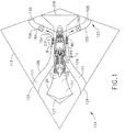
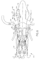
- FIG. 1 is a schematical cross-sectional view illustration of an aircraft thrust vectoring aft FLADE gas turbine engine with a short FLADE duct and dual thrust vectoring nozzles installed in an aircraft.
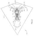
- FIG. 2 is a schematical cross-sectional view illustration of a thrust vectoring aft FLADE gas turbine engine with a long duct FLADE duct and dual thrust vectoring nozzles installed in an aircraft.
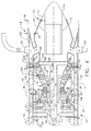
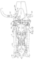
- FIG. 3 is a schematical cross-sectional view illustration of the aft FLADE gas turbine engine with a single direction of rotation fan section and an aft FLADE blade and turbine illustrated in FIGS. 1 and 2.
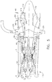
- FIG. 4 is a schematical cross-sectional view illustration of an alternative aft FLADE gas turbine engine with two fan sections and two bypass inlets.
- FIG. 5 is an alternative schematical cross-sectional view illustration of the engine in FIG. 3 with exhaust nozzle cooling.
- FIG. 6 is a schematical cross-sectional view illustration of another exemplary embodiment of an aircraft thrust vectoring aft FLADE gas turbine engine with an aft FLADE blade and turbine and a short FLADE duct.
- FIG. 7 is a schematical cross-sectional view illustration of the aircraft thrust vectoring aft FLADE aircraft gas turbine engine illustrated in FIG. 3 with a first afterburner upstream of a free aft FLADE turbine.
- FIG. 8 is a schematical cross-sectional view illustration of the aft FLADE gas turbine engine illustrated in FIG. 3 with a variable area turbine nozzle and a thrust augmenting afterburner downstream of an aft FLADE turbine.
- FIG. 9 is a schematical cross-sectional view illustration of yet another embodiment of an aircraft thrust vectoring aft FLADE aircraft gas turbine engine with counter-rotatable fans and an aft FLADE blade and turbine.
- FIG. 10 is a schematical cross-sectional view illustration of the aft FLADE gas turbine engine illustrated in FIG. 3 with an aft FLADE blade and turbine driving connected to a power takeoff shaft.
- FIG. 11 is a schematical cross-sectional view illustration of the aft FLADE gas turbine engine illustrated in FIG. 3 with an aft FLADE blade and turbine driving connected to an electrical generator located within the engine.
- FIG. 12 is a schematical cross-sectional view illustration of the aft FLADE gas turbine engine illustrated in FIG. 3 with an aft FLADE blade and turbine driving connected to two electrical generators located within the engine.
- Schematically illustrated in cross-section in FIG. 1 is an exemplary embodiment of an
aircraft 124 having a single offset flush mountedengine air intake 127 connected to and in fluid communication with an aircraft thrust vectoring aft FLADE aircraft gas turbine engine 1. Anannular fan inlet 11 of the aircraft aft FLADE engine 1 is connected to theair intake 127 by an engine fixedinlet duct 126. Thefan inlet 11 is axially offset from anannular FLADE inlet 8 to aFLADE duct 3. Flush mounted dualFLADE air intakes 129 are connected to and in fluid communication with theannular FLADE inlets 8 by FLADE fixedinlet ducts 128. - The
FLADE air intakes 129 are axially offset from theengine air intake 127. This provides great flexibility in designing and constructing efficient engines, aircraft, and aircraft with engines completely mounted within the aircraft'sfuselage 113 or body and theFLADE air intakes 129 and theengine air intake 127 are mounted flush with respect to thefuselage 113.Inlet duct passages 111 of the engine fixedinlet duct 126 and the FLADE fixedinlet ducts 128 may be two-dimensional terminating intransition sections 119 between theinlet duct passages 111 and the axisymmetric annular fan andFLADE inlets - The
FLADE duct 3 leads to at least onethrust vectoring nozzle 123 for maneuvering the aircraft. Right and left handFLADE exhaust nozzles thrust vectoring nozzles 123. The right and left handFLADE exhaust nozzles engine exhaust nozzle 218 which may be a variable or fixed throat area engine nozzle. AFLADE airflow manifold 231 collectsFLADE exhaust airflow 154 from theFLADE duct 3 and directs it through FLADE air exhaust right andleft hand ducts FLADE exhaust nozzles - Right and
left hand valves left hand ducts FLADE exhaust airflow 154 that goes to each of the right and left handFLADE exhaust nozzles FLADE exhaust airflow 154 to the right and left handFLADE exhaust nozzles FLADE exhaust airflow 154 to the right and left handFLADE exhaust nozzles - Equal amounts of the
FLADE exhaust airflow 154 flowed through the right andleft hand valves left hand ducts FLADE exhaust nozzles FLADE exhaust nozzles FLADE exhaust nozzles - The engine 1 illustrated in FIGS. 1-3, 7, 8, 10, and 11 are of the single bypass type having but a
single bypass inlet 272 as compared to the engine 1 illustrated in FIGS. 4-6 and 9 having both the first andsecond bypass inlets fan bypass duct 40 and have counter-rotating first and core fans. Schematically illustrated in cross-section in FIG. 2 is an alternative exemplary embodiment of theaircraft 124 in which theFLADE duct 3 is a long duct extending to theannular fan inlet 11 of the aircraft aft FLADE engine 1. TheFLADE duct 3 is also connected to theair intake 127 by the engine fixedinlet duct 126. - Schematically illustrated in cross-section in FIG. 3 is an exemplary aircraft aft FLADE engine 1. The engine 1 illustrated in FIG. 3 includes a
fan section 115 with a single direction ofrotation fan 330 with threefan stages 332 downstream of afan inlet 11. Downstream and axially aft of thefan section 115 is acore engine 18 having an annularcore engine inlet 17 and a generally axially extending axis orcenterline 12 generally extending forward 14 and aft 16. A singlefan bypass duct 40 located downstream and axially aft of thefan section 115 circumscribes thecore engine 18. Thesingle bypass inlet 272 includes anannular splitter 293 to splitfan airflow 50 intobypass airflow 258 andcore airflow 256. - The
core engine 18 includes, in downstream serial axial flow relationship, ahigh pressure compressor 20, acombustor 22, and ahigh pressure turbine 23 having a row of highpressure turbine blades 24. Ahigh pressure shaft 26, disposed coaxially about thecenterline 12 of the engine 1, fixedly interconnects thehigh pressure compressor 20 and the highpressure turbine blades 24. The combination or assembly of thehigh pressure compressor 20 drivenly connected to thehigh pressure turbine 23 by thehigh pressure shaft 26 is designated ahigh pressure spool 47. - The
core engine 18 is effective for generating combustion gases. Pressurized air from thehigh pressure compressor 20 is mixed with fuel in thecombustor 22 and ignited, thereby, generating combustion gases. Some work is extracted from these gases by the highpressure turbine blades 24 which drives thehigh pressure compressor 20. The combustion gases are discharged from thecore engine 18 into single direction of rotationlow pressure turbine 319. Thelow pressure turbine 319 is drivingly connected to the single direction ofrotation fan 330 by alow pressure shaft 321, the combination or assembly being designated alow pressure spool 290. - A
mixer 49, illustrated as a lobed or chute mixer, is disposed downstream of and at an aft end of thefan bypass duct 40 and downstream of and aft of lowpressure turbine blades 328 of thelow pressure turbine 319. Themixer 49 is used to mixbypass air 78 withcore discharge air 70 exiting thelow pressure turbine 319 to form amixed flow 188. One alternative version of themixer 49 is an aft variable area bypass injector (VABI) door disposed at an aft end of thefan bypass duct 40 to mixbypass air 78 withcore discharge air 70. - Exhaust gases from the
mixer 49 are directed through anaft FLADE turbine 160 having a plurality of aftFLADE turbine blades 254 and located downstream and aft of themixer 49. TheFLADE duct 3 circumscribes anaft FLADE turbine 160. Anaft FLADE fan 2 includes at least one row of aftFLADE fan blades 5 which extend radially outwardly from and are drivenly connected to theaft FLADE turbine 160 across theFLADE duct 3 circumscribing theaft FLADE turbine 160. AFLADE airflow 80 is powered by the aftFLADE fan blades 5 and put to use downstream of the aftFLADE fan blades 5. The aftFLADE fan blades 5 extend radially outwardly from an annular rotatableFLADE turbine shroud 250 attached to and circumscribing the aftFLADE turbine blades 254 of theaft FLADE turbine 160. TheFLADE turbine shroud 250 separates the aftFLADE fan blades 5 from the aftFLADE turbine blades 254. - Schematically illustrated, in cross-section in FIG. 4, is an alternative exemplary aircraft aft FLADE engine 1. The engine 1 in FIG. 4 includes a
fan section 115 with afan 330 downstream of variableinlet guide vanes 4 at aninlet 11 and a longduct FLADE duct 3.Fairings 190 disposed across theFLADE duct 3 surroundvariable vane shafts 194 passing through theFLADE duct 3 that are used to vary and control the pitch of the variable inlet guide vanes 4. Downstream of thefan section 115 is acore engine 18 including, in downstream serial axial flow relationship, a core drivenfan 37 having a row of core drivenfan blades 36, ahigh pressure compressor 20, acombustor 22, and ahigh pressure turbine 23 having a row of highpressure turbine blades 24. Ahigh pressure shaft 26, disposed coaxially about thecenterline 12 of the engine 1, fixedly interconnects thehigh pressure compressor 20 and the highpressure turbine blades 24. The combination or assembly of the core drivenfan 37 and thehigh pressure compressor 20 drivenly connected to thehigh pressure turbine 23 by thehigh pressure shaft 26 is designated ahigh pressure spool 47. - A
first bypass inlet 42 to thefan bypass duct 40 is disposed axially between thefan section 115 and the core drivenfan 37. Thefan blades 333 of thefan 330 radially extend across afirst fan duct 138. A row of circumferentially spaced-apartfan stator vanes 35 radially extend across thefirst fan duct 138, downstream of thefan blades 333, and axially between thefan blades 333 and thefirst bypass inlet 42 to thefan bypass duct 40. The row of the core drivenfan blades 36 of the core drivenfan 37 radially extend across an annularsecond fan duct 142. Thesecond fan duct 142 begins axially aft of thefirst bypass inlet 42 and is disposed radially inwardly of thefan bypass duct 40. An annularfirst flow splitter 45 is radially disposed between thefirst bypass inlet 42 and thesecond fan duct 142. - The
full engine airflow 15 is split between theFLADE inlet 8 and thefan inlet 11. Afan airflow 50 passes through thefan inlet 11 and then thefan section 115. A firstbypass air portion 52 of thefan airflow 50 passes through thefirst bypass inlet 42 of thefan bypass duct 40 when a front variable area bypass injector (VABI)door 44 in thefirst bypass inlet 42 is open and with the remainingair portion 54 passing through the core drivenfan 37 and its row of core drivenfan blades 36. - A row of circumferentially spaced-apart core driven
fan stator vanes 34 within thesecond fan duct 142 are disposed axially between the row ofsecond fan blades 32 and the core drivenfan blades 36 of the core drivenfan 37. The row of the core drivenfan stator vanes 34 and the core drivenfan blades 36 of the core drivenfan 37 are radially disposed across thesecond fan duct 142. Avane shroud 106 divides the core drivenfan stator vanes 34 into radially inner and outer vane hub andtip sections fan shroud 108 divides the core drivenfan blades 36 into the radially inner and outer blade hub andtip sections - A second
bypass airflow portion 56 is directed through afan tip duct 146 across thevane tip sections 84 of the core drivenfan stator vanes 34 and across theblade tip sections 38 of the core drivenfan blades 36 into asecond bypass inlet 46 of asecond bypass duct 58 to thefan bypass duct 40. An optional middle variable area bypass injector (VABI)door 83 may be disposed at an aft end of thesecond bypass duct 58 for modulating flow through thesecond bypass inlet 46 to thefan bypass duct 40. - The
fan tip duct 146 includes the vane andfan shrouds second flow splitter 55 at a forward end of thevane shroud 106. First and second varying means 91 and 92 are provided for independently varying flow areas of the vane hub andtip sections tip sections tip sections tip sections - Another embodiment of the independently variable vane hub and
tip sections tip sections - Exemplary first and second varying means 91 and 92, illustrated in FIG. 4, include an
inner shaft 94 coaxially disposed within anouter shaft 96. Theinner shaft 94 is rotated by afirst lever arm 98 actuated by afirst unison ring 100. Theouter shaft 96 is rotated by asecond lever arm 102 actuated by asecond unison ring 104. Theinner shaft 94 is attached to the pivotable trailingedge hub flap 86 of thevane hub section 85 of thefan stator vane 34. Theouter shaft 96 is attached to the pivotable trailingedge tip flap 88 of thevane tip section 84 of thefan stator vane 34. It is noted that thelever arms - Referring to FIG. 4 by way of example, a variable throat area main
engine exhaust nozzle 218, having a variable throat area A8, is downstream and axially aft of theaft FLADE turbine 160 and thefan bypass duct 40. The mainengine exhaust nozzle 218 includes an axially translatable radially outer annular convergent anddivergent wall 220 spaced radially outwardly apart from a radially fixed and axially translatable annularinner wall 222 on thecenterbody 72. The translatable radially outer annular convergent anddivergent wall 220 controls a throat area A8 between the outer annular convergent anddivergent wall 220 and the radially fixed and axially translatable annularinner wall 222. The translatable radially outer annular convergent anddivergent wall 220 also controls a nozzle exit area A9 of the mainengine exhaust nozzle 218. Alternatively, a variable throat area convergent/divergent nozzle with flaps may be used as disclosed in U.S. Patent No. 5,404,713. Illustrated in FIGS. 3, 10, and 11 is a fixed throatarea engine nozzle 216 axially aft of themixer 49 and thefan bypass duct 40. - The plurality of circumferentially disposed
hollow struts 208 are in fluid communication with and operable to receive air from theFLADE duct 3. The hollow struts 208 structurally support and flow air to thecenterbody 72 which is substantially hollow. A variable areaFLADE air nozzle 213 includes an axiallytranslatable plug 172 which cooperates with a radially outwardly positioned fixednozzle cowling 174 of thecenterbody 72 to exhaustFLADE airflow 80 received from thehollow struts 208 and return work to the engine in the form of thrust. - An optional variable
area turbine nozzle 180 with variableturbine nozzle vanes 182 is illustrated in FIG. 4 located between themixer 49 and theaft FLADE turbine 160. Variable areanozzle vane shafts 192, that are used to vary and control the pitch of the variableturbine nozzle vanes 182, pass through thevariable vane shafts 194 that are used to vary and control the pitch of the variablefirst FLADE vanes 6. A row ofsecond FLADE vanes 7 is illustrated in FIG. 1 as being fixed but may be variable. The row ofsecond FLADE vanes 7 is also located within theFLADE duct 3 but axially aftwardly and downstream of the row ofFLADE fan blades 5. Thesecond FLADE vanes 7 are used to deswirl theFLADE airflow 80. - FIGS. 5-8 illustrate a nozzle cooling arrangement in which at least some of the
FLADE airflow 80 is used as coolingair 251 which flowed through thehollow struts 208 into the substantiallyhollow centerbody 72. The coolingair 251 is then flowed through coolingapertures 249 in thecenterbody 72 downstream of the variable throat area A8 to cool an outer surface of the centerbody. Some of theFLADE airflow 80 may also be used as coolingair 251 for cooling the radially annularouter wall 220 of the mainengine exhaust nozzle 218 downstream of the variable throat area A8 in the same manner. Cooling of the annularouter wall 220 and thehollow centerbody 72 is helpful when thrust augmenting forward andaft afterburners afterburner 226 is forward and upstream of theaft FLADE turbine 160 and theaft afterburner 224 is aft and downstream of theaft FLADE turbine 160. The apertures may be angled to provide film cooling along thecenterbody 72 and/or thehollow struts 208. Holes, shaped and angled holes, and slots and angled slots are among the types of coolingapertures 249 that may be used. - Referring to FIG. 8, the augmenter includes an
exhaust casing 233 andliner 234 within which is defined acombustion zone 236. Thethrust augmenting afterburner 224 is mounted between the turbines and the exhaust nozzle for injecting additional fuel when desired during reheat operation for burning in the augmenter for producing additional thrust. In a bypass turbofan engine, an annular bypass duct extends from the fan to the augmenter for bypassing a portion of the fan air around the core engine to the augmenter. The bypass air is used in part for cooling the exhaust liner and also is mixed with the core gases prior to discharge through the exhaust nozzle. - Various types of flameholders are known and typically include radial and circumferential V-shaped gutters which provide local low velocity recirculation and stagnation regions therebehind, in otherwise high velocity core gas flow, for sustaining combustion during reheat operation. Since the core gases are the product of combustion in the core engine, they are initially hot when they leave the turbine, and are further heated when burned with the bypass air and additional fuel during reheat operation.
- The embodiments of the engine 1 illustrated in FIGS. 3 and 6 have the
fan inlet 11 to thefan section 115 axially offset from theannular FLADE inlet 8 to theFLADE duct 3. The exemplary axially offsetFLADE inlet 8 is illustrated as being axially located substantially aftwardly of thefan section 115 and, more particularly, it is axially located aftwardly of thecore engine 18. - Further illustrated in FIG. 3 is a variation of the embodiment of the aft FLADE engine 1 incorporating a "bolt on" aft
FLADE module 260 which incorporates a freeaft FLADE turbine 160 and can be added to an existingengine 262 for various purposes including, but not limited to, testing and design verification. Another feature illustrated in FIG. 3 is a FLADEpower extraction apparatus 264, illustrated as anelectrical generator 266 disposed within the engine 1 and drivenly connected through aspeed increasing gearbox 268 to theaft FLADE turbine 160. Theelectrical generator 266 is illustrated as being located within the hollowengine nozzle centerbody 72 but may be placed elsewhere in the engine 1 as illustrated in FIG. 12. - Another embodiment of the
power extraction apparatus 264 is apower takeoff assembly 270, as illustrated in FIG. 10, including ahousing 274 disposed within the hollowengine nozzle centerbody 72. Apower takeoff shaft 276 is drivenly connected to theaft FLADE turbine 160 through aright angle gearbox 278 within thehousing 274. A power takeoff shaft is typically used to drive accessory machinery mounted external to the engine such as gearboxes, generators, oil and fuel pumps. The FLADEpower extraction apparatus 264 allows more flexibility in the design of the engine 1 so that the power used by the aftFLADE fan blades 5 is a small percentage of the power extracted by theaft FLADE turbine 160 from themixed flow 188 and, therefore, varying and controlling the amount of theFLADE airflow 80 will have a small effect on the efficiency of theaft FLADE turbine 160. - Illustrated in FIG. 11 is an engine 1 with the
FLADE inlet 8 and thefan inlet 11 axially located together and not axially offset from each other as the embodiments illustrated in FIGS. 3 and 6. The engine 1 includes a longduct FLADE duct 3. Theelectrical generator 266 is disposed within the hollowengine nozzle centerbody 72 and drivingly connected through thespeed increasing gearbox 268 to theaft FLADE turbine 160. Thefan 330 is downstream of variableinlet guide vanes 4 at theinlet 11.Fairings 190 disposed across theFLADE duct 3 surroundvariable vane shafts 194 passing through theFLADE duct 3 that are used to vary and control the pitch of the variable inlet guide vanes 4. - Illustrated in FIG. 12 is a portion of an engine 1 with more than one FLADE
power extraction apparatus 264 disposed within the engine 1. Forward and aftelectrical generators aft FLADE turbine 160. The forward and aftelectrical generators speed increasing gearboxes aft FLADE turbine 160. Also illustrated in FIGS. 10-12 is a fixed throat area mainengine exhaust nozzle 216 having a fixed throat area A8 downstream and axially aft of theaft FLADE turbine 160. Power extraction may be accomplished in such a fixed throat area engine with the variablefirst FLADE vanes 6 scheduled closed. - Illustrated in FIG. 7 is an engine 1 with a
forward afterburner 226 axially disposed in themixed flow 188 between themixer 49 and theaft FLADE turbine 160. Theforward afterburner 226 includes forward fuel spraybars 230 andforward flameholders 232. Theforward afterburner 226 may be used to add additional energy to themixed flow 188 upstream of theaft FLADE turbine 160 if more power is required for theaft FLADE turbine 160 to provide additional energy upon demand to theaft FLADE turbine 160 for the aftFLADE fan blades 5 and/or thepower extraction apparatus 264 such as theelectrical generator 266 or thepower takeoff assembly 270. - Schematically illustrated in cross-section in FIG. 9 is an aircraft aft FLADE engine 1 having a
fan section 115 with first and secondcounter-rotatable fans first FLADE vanes 6 are used to control the amount of aFLADE airflow 80 allowed into theFLADE inlet 8 and theFLADE duct 3. Opening of theFLADE duct 3 by opening thefirst FLADE vanes 6 at part power thrust setting of the FLADE engine 1 allows the engine to maintain an essentially constant inlet airflow over a relatively wide range of thrust at a given set of subsonic flight ambient conditions such as altitude and flight Mach No. and also avoid spillage drag and to do so over a range of flight conditions. This capability is particularly needed for subsonic part power engine operating conditions. - The
FLADE inlet 8 and thefan inlet 11 in combination generally form theengine inlet 13. Downstream and axially aft of the first and secondcounter-rotatable fans core engine 18 having an annularcore engine inlet 17 and a generally axially extending axis orcenterline 12 generally extending forward 14 and aft 16. Afan bypass duct 40 located downstream and axially aft of the first and secondcounter-rotatable fans core engine 18. TheFLADE duct 3 circumscribes the first and secondcounter-rotatable fans fan bypass duct 40. - One important criterion of inlet performance is the ram recovery factor. A good inlet must have air-handling characteristics which are matched with the engine, as well as low drag and good flow stability. For a given set of operating flight conditions, the airflow requirements are fixed by the pumping characteristics of the FLADE engine 1. During supersonic operation of the engine, if the area of the
engine inlet 13 is too small to handle, the inlet airflow the inlet shock moves downstream of an inlet throat, particularly, if it is a fixed inlet and pressure recovery across the shock worsens and the exit corrected flow from the inlet increases to satisfy the engine demand. If the FLADE engine inlet area is too large, theengine inlet 13 will supply more air than the engine can use resulting in excess drag (spillage drag), because we must either by-pass the excess air around the engine or "spill" it back out of the inlet. Too much air or too little air is detrimental to aircraft system performance. TheFLADE fan 2 and theFLADE duct 3 are designed and operated to help manage the inlet airflow delivered by the inlet to the fans. - The
core engine 18 includes, in downstream serial axial flow relationship, a core drivenfan 37 having a row of core drivenfan blades 36, ahigh pressure compressor 20, acombustor 22, and ahigh pressure turbine 23 having a row of highpressure turbine blades 24. Ahigh pressure shaft 26, disposed coaxially about thecenterline 12 of the engine 1, connects thehigh pressure compressor 20 and core drivenfan 37 to thehigh pressure turbine 23 with the highpressure turbine blades 24. Thecore engine 18 is effective for generating combustion gases. Pressurized air from thehigh pressure compressor 20 is mixed with fuel in thecombustor 22 and ignited, thereby, generating combustion gases. Some work is extracted from these gases by the highpressure turbine blades 24 which drives the core drivenfan 37 and thehigh pressure compressor 20. Thehigh pressure shaft 26 rotates the core drivenfan 37 having a single row of circumferentially spaced apart core drivenfan blades 36 having generally radially outwardly locatedblade tip sections 38 separated from generally radially inwardly locatedblade hub sections 39 by anannular fan shroud 108. - The combustion gases are discharged from the
core engine 18 into a lowpressure turbine section 150 having counter-rotatable first and secondlow pressure turbines pressure turbine blades 28 and 29, respectively. The secondlow pressure turbine 21 is drivingly connected to the firstcounter-rotatable fan 130 by a firstlow pressure shaft 31, the combination or assembly being designated a firstlow pressure spool 242. The firstlow pressure turbine 19 is drivingly connected to the secondcounter-rotatable fan 132 by a secondlow pressure shaft 30, the combination or assembly being designated a secondlow pressure spool 240. The secondcounter-rotatable fan 132 has a single row of generally radially outwardly extending and circumferentially spaced-apartsecond fan blades 32. The firstcounter-rotatable fan 130 has a single row of generally radially outwardly extending and circumferentially spaced-apartfirst fan blades 33. The aftFLADE fan blades 5 are primarily used to flexibly match inlet airflow requirements. - The
high pressure turbine 23 includes a row of high pressure turbine (HPT)nozzle stator vanes 110 which directs flow from thecombustor 22 to the row of highpressure turbine blades 24. Flow from the row of highpressure turbine blades 24 is then directed into counter-rotatable second and firstlow pressure turbines pressure turbine blades 29 and 28, respectively. - A row of fixed low
pressure stator vanes 66 is disposed between the second and first rows of lowpressure turbine blades 29 and 28. Alternatively, a row of variable low pressure stator vanes may be incorporated between the second and first rows of lowpressure turbine blades 29 and 28. The firstlow pressure turbine 19 and its first row of low pressure turbine blades 28 are counter-rotatable with respect to the row of highpressure turbine blades 24. The firstlow pressure turbine 19 and its first row of low pressure turbine blades 28 are counter-rotatable with respect to the secondlow pressure turbine 21 and its second row of lowpressure turbine blades 29. Theaft FLADE turbine 160 is illustrated, in FIG. 9 as a free turbine not connected to a spool or fan in thefan section 115. Alternatively, theaft FLADE turbine 160 may be drivingly connected to the firstlow pressure shaft 31 of the secondlow pressure spool 242. - The total flow available for vectoring is set by the rotational speed of the aft FLADE fan and the setting of the variable
first FLADE vanes 6. The right andleft hand valves FLADE exhaust nozzles aft FLADE turbine 160 and aftFLADE fan 2 operate. The turbofan engine operating conditions may be modulated as necessary to provide the desired combination of overall propulsion system thrust and vectoring forces. Turbofan engine controls would be modified or configured to react to the demands of the thrust vectoring system. This may be achieved by biasing existing control schedules based on the variablefirst FLADE vane 6 and the right andleft hand valves aft FLADE turbine 160 and thefan inlet 11 of the aircraft aft FLADE engine 1. - The engines illustrated herein are single and double bypass types and it is thought that a turbojet type may be used in which there is no bypass duct or bypass flow and the aft FLADE turbine would be placed downstream of any turbine section used to drive the fan and/or compressor. Turbojet type engines may also use augmenters and variable area two-dimensional nozzles.
Claims (10)
- An aft FLADE gas turbine engine (1) comprising:a fan section (115) drivenly connected to a low pressure turbine section (150),a core engine (18) located between the fan section (115) and the low pressure turbine section (150),an aft FLADE turbine (160) downstream of the low pressure turbine section (150),at least one row of aft FLADE fan blades (5) disposed radially outwardly of and connected to the aft FLADE turbine (160),the row of aft FLADE fan blades (5) radially extending across a FLADE duct (3) circumscribing the aft FLADE turbine (160), andat least one thrust vectoring nozzle (123) in pressurized fluid flow receiving communication with the FLADE duct (3).
- An aft FLADE gas turbine engine (1) as claimed in claim 1 further comprising:the one thrust vectoring nozzle (123) being a right hand FLADE exhaust nozzle (125),a left hand FLADE exhaust nozzle (135) in pressurized fluid flow receiving communication with the FLADE duct (3), andthe right and left hand FLADE exhaust nozzle (125 and 135) are offset from a main engine exhaust nozzle (218) located downstream of the aft FLADE turbine (160).
- An aft FLADE gas turbine engine (1) as claimed in claim 2 wherein the right and left hand FLADE exhaust nozzle (125 and 135) are fixed nozzles or thrust vectoring nozzles.
- An aft FLADE gas turbine engine (1) as claimed in claim 2 further comprising:a FLADE airflow manifold (231) in pressurized fluid flow receiving communication with the FLADE duct (3),the right and left hand FLADE exhaust nozzles (125 and 135) connected in pressurized fluid flow receiving communication with the FLADE airflow manifold (231) by FLADE air exhaust right and left hand ducts (155 and 156) respectively,right and left hand valves (162 and 164) respectively disposed in the right and left hand ducts (155 and 156), andthe right and left hand valves (162 and 164) being operable to control amounts of FLADE exhaust airflow (154) flowed from the FLADE duct (3) to each of the right and left hand FLADE exhaust nozzles (125 and 135) respectively.
- An aft FLADE gas turbine engine (1) as claimed in claim 4 further comprising:a fan bypass duct (40) circumscribing the core engine (18) and in fluid communication with the fan section (115),a mixer (49) in fluid communication with the fan bypass duct (40) and being operably disposed to mix bypass air (78) from the fan bypass duct (40) with core discharge air (70) exiting the low pressure turbine section (150), andthe aft FLADE turbine (160) being downstream of the mixer (49).
- An engine (1) as claimed in claim 5 wherein the aft FLADE turbine (160) is a free turbine.
- An engine (1) as claimed in claim 14 further comprising a variable area turbine nozzle (180) with variable turbine nozzle vanes (182) located between the mixer (49) and the aft FLADE turbine (160).
- An engine (1) as claimed in claim 7 further comprising:a fan inlet (11) to the fan section (115),an annular FLADE inlet (8) to the FLADE duct (3), andthe FLADE inlet (8) is axially located substantially axially aftwardly of the fan section (115).
- An aircraft (124) comprising:an aft FLADE gas turbine engine (1) according to any one of claims 1 to 8 within a fuselage (113) of the aircraft.
- An aircraft (124) as claimed in claim 9 further comprising:FLADE air intakes (129) and an engine air intake (127) mounted flush with respect to the fuselage (113),the FLADE air intakes (129) axially offset from the engine air intake (127),the engine air intake (127) connected to and in fluid communication with the fan inlet (11) by an engine fixed inlet duct (126), andthe FLADE air intakes (129) connected to and in fluid communication with the FLADE inlets (8) by FLADE fixed inlet ducts (128).
Applications Claiming Priority (1)
| Application Number | Priority Date | Filing Date | Title |
|---|---|---|---|
| US10/982,477 US7134271B2 (en) | 2004-11-05 | 2004-11-05 | Thrust vectoring aft FLADE engine |
Publications (3)
| Publication Number | Publication Date |
|---|---|
| EP1655474A2 true EP1655474A2 (en) | 2006-05-10 |
| EP1655474A3 EP1655474A3 (en) | 2011-07-27 |
| EP1655474B1 EP1655474B1 (en) | 2013-10-30 |
Family
ID=35695780
Family Applications (1)
| Application Number | Title | Priority Date | Filing Date |
|---|---|---|---|
| EP05256717.9A Expired - Fee Related EP1655474B1 (en) | 2004-11-05 | 2005-10-31 | Thrust vectoring aft flade engine |
Country Status (4)
| Country | Link |
|---|---|
| US (1) | US7134271B2 (en) |
| EP (1) | EP1655474B1 (en) |
| JP (1) | JP4820619B2 (en) |
| CN (1) | CN100549398C (en) |
Cited By (8)
| Publication number | Priority date | Publication date | Assignee | Title |
|---|---|---|---|---|
| EP1939426A2 (en) * | 2006-12-18 | 2008-07-02 | General Electric Company | System for supplying air to a vehicle having a turbofan engine |
| FR2941492A1 (en) * | 2009-01-23 | 2010-07-30 | Snecma | POWER TURBINE TURBINE ENGINE COMPRISING AN ELECTRONIC POWER GENERATOR CENTERED ON THE AXIS OF TURBOMACHINE |
| WO2011038216A1 (en) * | 2009-09-25 | 2011-03-31 | General Electric Company | A convertible fan engine comprising a two block compressor |
| WO2011038213A1 (en) * | 2009-09-25 | 2011-03-31 | General Electric Company | Convertible fan engine |
| WO2014130361A1 (en) | 2013-02-19 | 2014-08-28 | United Technologies Corporation | Turbofan engine including third flowpath exhaust nozzle |
| EP3239511A1 (en) * | 2016-04-27 | 2017-11-01 | General Electric Company | Turbofan assembly and method of assembling |
| FR3050766A1 (en) * | 2016-04-29 | 2017-11-03 | Snecma | DOUBLE FLOW TURBOREACTOR WITH FLOW SAMPLING FOR ADJUSTABLE CALIBRATION OF DILUTION RATE TO CONFLUENCE |
| US10358229B2 (en) | 2015-05-13 | 2019-07-23 | Rolls-Royce Plc | Aircraft |
Families Citing this family (54)
| Publication number | Priority date | Publication date | Assignee | Title |
|---|---|---|---|---|
| EP1780387A3 (en) * | 2000-09-05 | 2007-07-18 | Sudarshan Paul Dev | Nested core gas turbine engine |
| EP1931870B1 (en) * | 2005-09-27 | 2011-09-07 | Volvo Aero Corporation | An arrangement for propelling an aircraft, aircraft and outlet nozzle for a jet engine |
| US7758303B1 (en) | 2006-07-31 | 2010-07-20 | General Electric Company | FLADE fan with different inner and outer airfoil stagger angles at a shroud therebetween |
| US7926290B2 (en) * | 2006-12-18 | 2011-04-19 | General Electric Company | Turbine engine with modulated flow fan and method of operation |
| US20090067978A1 (en) * | 2007-05-24 | 2009-03-12 | Suljak Jr George T | Variable area turbine vane arrangement |
| US8007229B2 (en) * | 2007-05-24 | 2011-08-30 | United Technologies Corporation | Variable area turbine vane arrangement |
| US7942632B2 (en) * | 2007-06-20 | 2011-05-17 | United Technologies Corporation | Variable-shape variable-stagger inlet guide vane flap |
| FR2919896B1 (en) * | 2007-08-07 | 2009-10-30 | Snecma Sa | TURBOREACTOR COMPRISING A CURRENT GENERATOR MOUNTED IN THE BLOWER AND A METHOD FOR MOUNTING THE SAME GENERATOR IN THE SOUFFLANTE |
| US8708643B2 (en) * | 2007-08-14 | 2014-04-29 | General Electric Company | Counter-rotatable fan gas turbine engine with axial flow positive displacement worm gas generator |
| FR2921042B1 (en) * | 2007-09-14 | 2010-05-14 | Airbus | SMOKE GENERATION DEVICE FOR AIRCRAFT AND AIRCRAFT EQUIPPED WITH SUCH A DEVICE |
| US8322127B2 (en) * | 2007-11-01 | 2012-12-04 | United Technologies Corporation | Nozzle assembly with flow conduits |
| US8105019B2 (en) * | 2007-12-10 | 2012-01-31 | United Technologies Corporation | 3D contoured vane endwall for variable area turbine vane arrangement |
| US8739548B2 (en) * | 2007-12-20 | 2014-06-03 | United Technologies Corporation | Sliding ramp nozzle system for a gas turbine engine |
| US9267463B2 (en) * | 2008-03-25 | 2016-02-23 | United Technologies Corp. | Gas turbine engine systems involving variable nozzles with flexible panels |
| US8356483B2 (en) * | 2008-04-10 | 2013-01-22 | United Technologies Corp | Gas turbine engine systems involving variable nozzles with sliding doors |
| US20100031669A1 (en) * | 2008-08-06 | 2010-02-11 | Cessna Aircraft Company | Free Turbine Generator For Aircraft |
| EP2177735A3 (en) * | 2008-10-20 | 2012-02-15 | Rolls-Royce North American Technologies, Inc. | Turbofan |
| GB2474286B (en) * | 2009-10-12 | 2011-08-31 | Rolls Royce Plc | A propulsion engine |
| US8714919B2 (en) * | 2009-11-06 | 2014-05-06 | Raytheon Company | Inlet and exhaust system |
| US20110146289A1 (en) * | 2009-12-21 | 2011-06-23 | John Lewis Baughman | Power extraction method |
| US20110146228A1 (en) * | 2009-12-21 | 2011-06-23 | John Lewis Baughman | Power extraction system |
| DE102010009477A1 (en) * | 2010-02-26 | 2011-09-01 | Rolls-Royce Deutschland Ltd & Co Kg | Aircraft gas turbine engine |
| US20110240804A1 (en) * | 2010-04-01 | 2011-10-06 | Nikolaos Kehayas | Integrated aircraft |
| CN101881237A (en) * | 2010-06-22 | 2010-11-10 | 季承 | Turbofan postpose type engine |
| US9016041B2 (en) * | 2010-11-30 | 2015-04-28 | General Electric Company | Variable-cycle gas turbine engine with front and aft FLADE stages |
| US8984891B2 (en) | 2010-12-30 | 2015-03-24 | General Electric Company | Flade discharge in 2-D exhaust nozzle |
| CN102128084A (en) * | 2011-02-18 | 2011-07-20 | 张旭 | Thermal power device for turbine fan engine |
| CN102305152A (en) * | 2011-05-20 | 2012-01-04 | 中国科学院工程热物理研究所 | Hybrid exhaust aircraft engine |
| US8516789B2 (en) * | 2011-07-26 | 2013-08-27 | United Technologies Corporation | Gas turbine engine with aft core driven fan section |
| US9777631B2 (en) * | 2011-09-30 | 2017-10-03 | General Electric Company | Conformal inlet apparatus for a gas turbine engine |
| US9188083B2 (en) * | 2011-10-28 | 2015-11-17 | United Technologies Corporation | Gas turbine engine with auxiliary fan |
| US9523329B2 (en) * | 2013-03-15 | 2016-12-20 | United Technologies Corporation | Gas turbine engine with stream diverter |
| US10400710B2 (en) * | 2013-05-07 | 2019-09-03 | General Electric Company | Secondary nozzle for jet engine |
| US9920710B2 (en) * | 2013-05-07 | 2018-03-20 | General Electric Company | Multi-nozzle flow diverter for jet engine |
| US9909529B2 (en) * | 2013-09-20 | 2018-03-06 | United Technologies Corporation | Flow path routing within a gas turbine engine |
| US10371090B2 (en) | 2014-01-13 | 2019-08-06 | United Technologies Corporation | Variable area exhaust mixer for a gas turbine engine |
| US10030606B2 (en) | 2014-01-27 | 2018-07-24 | United Technologies Corporation | Variable exhaust mixer and cooler for a three-stream gas turbine engine |
| US9951721B2 (en) | 2014-10-21 | 2018-04-24 | United Technologies Corporation | Three-stream gas turbine engine architecture |
| US10421553B2 (en) * | 2015-01-20 | 2019-09-24 | United Technologies Corporation | Pusher fan engine with in wing configuration |
| CN104590567A (en) * | 2015-01-22 | 2015-05-06 | 谭现东 | Aerocraft |
| WO2016189712A1 (en) | 2015-05-27 | 2016-12-01 | 株式会社Ihi | Jet engine |
| US9850794B2 (en) * | 2015-06-29 | 2017-12-26 | General Electric Company | Power generation system exhaust cooling |
| US10151217B2 (en) * | 2016-02-11 | 2018-12-11 | General Electric Company | Turbine frame cooling systems and methods of assembly for use in a gas turbine engine |
| GB201610958D0 (en) * | 2016-06-23 | 2016-08-10 | Rolls Royce Plc | Gas turbine exhaust cooling system |
| US10822100B2 (en) * | 2017-06-26 | 2020-11-03 | General Electric Company | Hybrid electric propulsion system for an aircraft |
| CN108910057B (en) * | 2018-06-10 | 2024-03-29 | 东莞理工学院 | Flying wing unmanned aerial vehicle with multiple engines |
| US11719113B2 (en) | 2020-02-05 | 2023-08-08 | Raytheon Technologies Corporation | Cooling system for power cables in a gas turbine engine |
| US11814152B2 (en) | 2020-07-20 | 2023-11-14 | The Boeing Company | Methods and apparatus for accelerating an aircraft fuselage boundary layer via a fan powered by an auxiliary power unit of the aircraft |
| US11585291B2 (en) * | 2020-09-11 | 2023-02-21 | Raytheon Technologies Corporation | Tail cone ejector for power cable cooling system in a gas turbine engine |
| KR102492920B1 (en) * | 2020-10-05 | 2023-01-31 | 연세대학교 산학협력단 | Airfoil-Shaped Aircraft |
| US11578657B2 (en) | 2020-10-27 | 2023-02-14 | Raytheon Technologies Corporation | Power cable cooling system in a gas turbine engine |
| US11781479B2 (en) * | 2021-05-06 | 2023-10-10 | Rtx Corporation | Turbofan gas turbine engine with combusted compressor bleed flow |
| US11408343B1 (en) * | 2021-05-06 | 2022-08-09 | Raytheon Technologies Corporation | Turboshaft engine with axial compressor |
| GB202210142D0 (en) * | 2022-07-11 | 2022-08-24 | Rolls Royce Plc | Gas turbine engine |
Citations (9)
| Publication number | Priority date | Publication date | Assignee | Title |
|---|---|---|---|---|
| US133746A (en) | 1872-12-10 | Improvement in steam water-elevators | ||
| US4043121A (en) | 1975-01-02 | 1977-08-23 | General Electric Company | Two-spool variable cycle engine |
| EP0567277A1 (en) | 1992-04-20 | 1993-10-27 | General Electric Company | Bypass injector valve for variable cycle aircraft engines |
| US5261227A (en) | 1992-11-24 | 1993-11-16 | General Electric Company | Variable specific thrust turbofan engine |
| US5402963A (en) | 1992-09-15 | 1995-04-04 | General Electric Company | Acoustically shielded exhaust system for high thrust jet engines |
| US5404713A (en) | 1993-10-04 | 1995-04-11 | General Electric Company | Spillage drag and infrared reducing flade engine |
| US5806303A (en) | 1996-03-29 | 1998-09-15 | General Electric Company | Turbofan engine with a core driven supercharged bypass duct and fixed geometry nozzle |
| US5809772A (en) | 1996-03-29 | 1998-09-22 | General Electric Company | Turbofan engine with a core driven supercharged bypass duct |
| US5988890A (en) | 1996-06-28 | 1999-11-23 | Mitsubishi Heavy Industries Co., Ltd. | Rotor shaft |
Family Cites Families (24)
| Publication number | Priority date | Publication date | Assignee | Title |
|---|---|---|---|---|
| US2472839A (en) * | 1945-06-01 | 1949-06-14 | Westinghouse Electric Corp | Steering nozzle for jet-propelled aircraft |
| US3348379A (en) * | 1963-09-25 | 1967-10-24 | Rolls Royce | Turbojet engine with compressor bypass and aft fan |
| DE1198131B (en) * | 1964-02-12 | 1965-08-05 | Daimler Benz Ag | Dual-circuit gas turbine jet engine |
| US3673802A (en) | 1970-06-18 | 1972-07-04 | Gen Electric | Fan engine with counter rotating geared core booster |
| GB1330904A (en) * | 1971-04-19 | 1973-09-19 | Secr Defence | Gas turbine jet propulsion engines |
| DE2149619A1 (en) * | 1971-10-05 | 1973-04-19 | Motoren Turbinen Union | TURBINE JET FOR VERTICAL OR SHORT-STARTING OR LANDING AIRPLANES |
| US4068471A (en) | 1975-06-16 | 1978-01-17 | General Electric Company | Variable cycle engine with split fan section |
| US4222235A (en) | 1977-07-25 | 1980-09-16 | General Electric Company | Variable cycle engine |
| US4232515A (en) | 1978-03-06 | 1980-11-11 | The Boeing Company | Supersonic cruise airplane and engine |
| US4463772A (en) | 1981-09-29 | 1984-08-07 | The Boeing Company | Flush inlet for supersonic aircraft |
| US4552309A (en) * | 1982-04-07 | 1985-11-12 | Rolls-Royce Inc. | Variable geometry nozzles for turbomachines |
| GB2246171B (en) * | 1986-06-21 | 1992-04-08 | British Aerospace | Improvements in or related to gas turbine engines |
| GB8812978D0 (en) * | 1988-06-01 | 1988-11-16 | British Aerospace | Nozzle assembly for aircraft |
| FR2645911B1 (en) * | 1989-04-18 | 1991-06-07 | Snecma | HIGH DILUTION MOTOR WITH UPSTREAM BLOWER AND DOWNSTREAM BLOWER |
| GB8924871D0 (en) * | 1989-11-03 | 1989-12-20 | Rolls Royce Plc | Tandem fan engine |
| US5388964A (en) | 1993-09-14 | 1995-02-14 | General Electric Company | Hybrid rotor blade |
| US5402638A (en) | 1993-10-04 | 1995-04-04 | General Electric Company | Spillage drag reducing flade engine |
| US5779169A (en) * | 1995-12-15 | 1998-07-14 | The Boeing Company | Aircraft engine inlet hot gas and foreign object ingestion reduction and pitch control system |
| JPH1016893A (en) * | 1996-07-04 | 1998-01-20 | Mitsubishi Heavy Ind Ltd | Posture control device for airplane |
| US5794432A (en) | 1996-08-27 | 1998-08-18 | Diversitech, Inc. | Variable pressure and variable air flow turbofan engines |
| US5931636A (en) | 1997-08-28 | 1999-08-03 | General Electric Company | Variable area turbine nozzle |
| US6568635B2 (en) | 2001-07-02 | 2003-05-27 | Lockheed Martin Corporation | Apparatus and method for flight control of an aircraft |
| US6918244B2 (en) * | 2001-08-17 | 2005-07-19 | John Eugene Dickau | Vertical takeoff and landing aircraft propulsion systems |
| US6837038B2 (en) * | 2001-10-16 | 2005-01-04 | United Technologies Corporation | Variable cycle boost propulsor |
-
2004
- 2004-11-05 US US10/982,477 patent/US7134271B2/en active Active
-
2005
- 2005-10-27 JP JP2005312090A patent/JP4820619B2/en not_active Expired - Fee Related
- 2005-10-31 EP EP05256717.9A patent/EP1655474B1/en not_active Expired - Fee Related
- 2005-11-04 CN CNB2005101188057A patent/CN100549398C/en not_active Expired - Fee Related
Patent Citations (9)
| Publication number | Priority date | Publication date | Assignee | Title |
|---|---|---|---|---|
| US133746A (en) | 1872-12-10 | Improvement in steam water-elevators | ||
| US4043121A (en) | 1975-01-02 | 1977-08-23 | General Electric Company | Two-spool variable cycle engine |
| EP0567277A1 (en) | 1992-04-20 | 1993-10-27 | General Electric Company | Bypass injector valve for variable cycle aircraft engines |
| US5402963A (en) | 1992-09-15 | 1995-04-04 | General Electric Company | Acoustically shielded exhaust system for high thrust jet engines |
| US5261227A (en) | 1992-11-24 | 1993-11-16 | General Electric Company | Variable specific thrust turbofan engine |
| US5404713A (en) | 1993-10-04 | 1995-04-11 | General Electric Company | Spillage drag and infrared reducing flade engine |
| US5806303A (en) | 1996-03-29 | 1998-09-15 | General Electric Company | Turbofan engine with a core driven supercharged bypass duct and fixed geometry nozzle |
| US5809772A (en) | 1996-03-29 | 1998-09-22 | General Electric Company | Turbofan engine with a core driven supercharged bypass duct |
| US5988890A (en) | 1996-06-28 | 1999-11-23 | Mitsubishi Heavy Industries Co., Ltd. | Rotor shaft |
Cited By (11)
| Publication number | Priority date | Publication date | Assignee | Title |
|---|---|---|---|---|
| EP1939426A2 (en) * | 2006-12-18 | 2008-07-02 | General Electric Company | System for supplying air to a vehicle having a turbofan engine |
| EP1939426A3 (en) * | 2006-12-18 | 2012-12-19 | General Electric Company | System for supplying air to a vehicle having a turbofan engine |
| FR2941492A1 (en) * | 2009-01-23 | 2010-07-30 | Snecma | POWER TURBINE TURBINE ENGINE COMPRISING AN ELECTRONIC POWER GENERATOR CENTERED ON THE AXIS OF TURBOMACHINE |
| US7966833B2 (en) | 2009-01-23 | 2011-06-28 | Snecma | Turbine engine with a power turbine equipped with an electric power generator centered on the axis of the turbine engine |
| WO2011038216A1 (en) * | 2009-09-25 | 2011-03-31 | General Electric Company | A convertible fan engine comprising a two block compressor |
| WO2011038213A1 (en) * | 2009-09-25 | 2011-03-31 | General Electric Company | Convertible fan engine |
| WO2014130361A1 (en) | 2013-02-19 | 2014-08-28 | United Technologies Corporation | Turbofan engine including third flowpath exhaust nozzle |
| EP2959146A4 (en) * | 2013-02-19 | 2016-03-23 | United Technologies Corp | Turbofan engine including third flowpath exhaust nozzle |
| US10358229B2 (en) | 2015-05-13 | 2019-07-23 | Rolls-Royce Plc | Aircraft |
| EP3239511A1 (en) * | 2016-04-27 | 2017-11-01 | General Electric Company | Turbofan assembly and method of assembling |
| FR3050766A1 (en) * | 2016-04-29 | 2017-11-03 | Snecma | DOUBLE FLOW TURBOREACTOR WITH FLOW SAMPLING FOR ADJUSTABLE CALIBRATION OF DILUTION RATE TO CONFLUENCE |
Also Published As
| Publication number | Publication date |
|---|---|
| JP4820619B2 (en) | 2011-11-24 |
| US20060096272A1 (en) | 2006-05-11 |
| US7134271B2 (en) | 2006-11-14 |
| JP2006132533A (en) | 2006-05-25 |
| EP1655474A3 (en) | 2011-07-27 |
| CN1779224A (en) | 2006-05-31 |
| EP1655474B1 (en) | 2013-10-30 |
| CN100549398C (en) | 2009-10-14 |
Similar Documents
| Publication | Publication Date | Title |
|---|---|---|
| EP1655474B1 (en) | Thrust vectoring aft flade engine | |
| US7216475B2 (en) | Aft FLADE engine | |
| US7395657B2 (en) | Flade gas turbine engine with fixed geometry inlet | |
| US5404713A (en) | Spillage drag and infrared reducing flade engine | |
| US5402638A (en) | Spillage drag reducing flade engine | |
| US7475545B2 (en) | Fladed supersonic missile turbojet | |
| US9016041B2 (en) | Variable-cycle gas turbine engine with front and aft FLADE stages | |
| EP1942269B1 (en) | Convertible gas turbine engine | |
| US7246484B2 (en) | FLADE gas turbine engine with counter-rotatable fans | |
| EP1939438B1 (en) | Duct burning mixed flow turbofan | |
| US5867980A (en) | Turbofan engine with a low pressure turbine driven supercharger in a bypass duct operated by a fuel rich combustor and an afterburner | |
| US7758303B1 (en) | FLADE fan with different inner and outer airfoil stagger angles at a shroud therebetween | |
| EP2820278B1 (en) | Hybrid turbofan engine | |
| EP2472089B1 (en) | Flade discharge in 2-d exhaust nozzle | |
| EP2994633B1 (en) | Secondary nozzle for jet engine | |
| EP2472081B1 (en) | Variable cycle gas turbine engine | |
| GB2425516A (en) | Jet engine thrust vectoring using fluid jets | |
| CN117869012A (en) | Gas turbine exhaust nozzle noise reduction |
Legal Events
| Date | Code | Title | Description |
|---|---|---|---|
| PUAI | Public reference made under article 153(3) epc to a published international application that has entered the european phase |
Free format text: ORIGINAL CODE: 0009012 |
|
| AK | Designated contracting states |
Kind code of ref document: A2 Designated state(s): AT BE BG CH CY CZ DE DK EE ES FI FR GB GR HU IE IS IT LI LT LU LV MC NL PL PT RO SE SI SK TR |
|
| AX | Request for extension of the european patent |
Extension state: AL BA HR MK YU |
|
| PUAL | Search report despatched |
Free format text: ORIGINAL CODE: 0009013 |
|
| AK | Designated contracting states |
Kind code of ref document: A3 Designated state(s): AT BE BG CH CY CZ DE DK EE ES FI FR GB GR HU IE IS IT LI LT LU LV MC NL PL PT RO SE SI SK TR |
|
| AX | Request for extension of the european patent |
Extension state: AL BA HR MK YU |
|
| 17P | Request for examination filed |
Effective date: 20120127 |
|
| 17Q | First examination report despatched |
Effective date: 20120221 |
|
| AKX | Designation fees paid |
Designated state(s): DE FR GB IT SE |
|
| GRAP | Despatch of communication of intention to grant a patent |
Free format text: ORIGINAL CODE: EPIDOSNIGR1 |
|
| GRAP | Despatch of communication of intention to grant a patent |
Free format text: ORIGINAL CODE: EPIDOSNIGR1 |
|
| INTG | Intention to grant announced |
Effective date: 20130524 |
|
| GRAS | Grant fee paid |
Free format text: ORIGINAL CODE: EPIDOSNIGR3 |
|
| GRAA | (expected) grant |
Free format text: ORIGINAL CODE: 0009210 |
|
| AK | Designated contracting states |
Kind code of ref document: B1 Designated state(s): DE FR GB IT SE |
|
| REG | Reference to a national code |
Ref country code: GB Ref legal event code: FG4D |
|
| REG | Reference to a national code |
Ref country code: DE Ref legal event code: R096 Ref document number: 602005041676 Country of ref document: DE Effective date: 20131224 |
|
| PG25 | Lapsed in a contracting state [announced via postgrant information from national office to epo] |
Ref country code: SE Free format text: LAPSE BECAUSE OF FAILURE TO SUBMIT A TRANSLATION OF THE DESCRIPTION OR TO PAY THE FEE WITHIN THE PRESCRIBED TIME-LIMIT Effective date: 20131030 |
|
| REG | Reference to a national code |
Ref country code: DE Ref legal event code: R097 Ref document number: 602005041676 Country of ref document: DE |
|
| PG25 | Lapsed in a contracting state [announced via postgrant information from national office to epo] |
Ref country code: IT Free format text: LAPSE BECAUSE OF FAILURE TO SUBMIT A TRANSLATION OF THE DESCRIPTION OR TO PAY THE FEE WITHIN THE PRESCRIBED TIME-LIMIT Effective date: 20131030 |
|
| PLBE | No opposition filed within time limit |
Free format text: ORIGINAL CODE: 0009261 |
|
| STAA | Information on the status of an ep patent application or granted ep patent |
Free format text: STATUS: NO OPPOSITION FILED WITHIN TIME LIMIT |
|
| 26N | No opposition filed |
Effective date: 20140731 |
|
| REG | Reference to a national code |
Ref country code: DE Ref legal event code: R097 Ref document number: 602005041676 Country of ref document: DE Effective date: 20140731 |
|
| REG | Reference to a national code |
Ref country code: FR Ref legal event code: PLFP Year of fee payment: 11 |
|
| REG | Reference to a national code |
Ref country code: FR Ref legal event code: PLFP Year of fee payment: 12 |
|
| PGFP | Annual fee paid to national office [announced via postgrant information from national office to epo] |
Ref country code: FR Payment date: 20161025 Year of fee payment: 12 Ref country code: GB Payment date: 20161027 Year of fee payment: 12 Ref country code: DE Payment date: 20161027 Year of fee payment: 12 |
|
| REG | Reference to a national code |
Ref country code: DE Ref legal event code: R119 Ref document number: 602005041676 Country of ref document: DE |
|
| GBPC | Gb: european patent ceased through non-payment of renewal fee |
Effective date: 20171031 |
|
| REG | Reference to a national code |
Ref country code: FR Ref legal event code: ST Effective date: 20180629 |
|
| PG25 | Lapsed in a contracting state [announced via postgrant information from national office to epo] |
Ref country code: DE Free format text: LAPSE BECAUSE OF NON-PAYMENT OF DUE FEES Effective date: 20180501 Ref country code: GB Free format text: LAPSE BECAUSE OF NON-PAYMENT OF DUE FEES Effective date: 20171031 |
|
| PG25 | Lapsed in a contracting state [announced via postgrant information from national office to epo] |
Ref country code: FR Free format text: LAPSE BECAUSE OF NON-PAYMENT OF DUE FEES Effective date: 20171031 |