EP1653640A1 - Fiberoptics, fiberoptic transmission line and optical transmission system - Google Patents
Fiberoptics, fiberoptic transmission line and optical transmission system Download PDFInfo
- Publication number
- EP1653640A1 EP1653640A1 EP04747308A EP04747308A EP1653640A1 EP 1653640 A1 EP1653640 A1 EP 1653640A1 EP 04747308 A EP04747308 A EP 04747308A EP 04747308 A EP04747308 A EP 04747308A EP 1653640 A1 EP1653640 A1 EP 1653640A1
- Authority
- EP
- European Patent Office
- Prior art keywords
- optical fiber
- core
- chromatic dispersion
- refractive index
- optical
- Prior art date
- Legal status (The legal status is an assumption and is not a legal conclusion. Google has not performed a legal analysis and makes no representation as to the accuracy of the status listed.)
- Withdrawn
Links
Images



Classifications
-
- H—ELECTRICITY
- H04—ELECTRIC COMMUNICATION TECHNIQUE
- H04B—TRANSMISSION
- H04B10/00—Transmission systems employing electromagnetic waves other than radio-waves, e.g. infrared, visible or ultraviolet light, or employing corpuscular radiation, e.g. quantum communication
- H04B10/25—Arrangements specific to fibre transmission
- H04B10/2507—Arrangements specific to fibre transmission for the reduction or elimination of distortion or dispersion
- H04B10/2543—Arrangements specific to fibre transmission for the reduction or elimination of distortion or dispersion due to fibre non-linearities, e.g. Kerr effect
- H04B10/2563—Four-wave mixing [FWM]
-
- G—PHYSICS
- G02—OPTICS
- G02B—OPTICAL ELEMENTS, SYSTEMS OR APPARATUS
- G02B6/00—Light guides; Structural details of arrangements comprising light guides and other optical elements, e.g. couplings
- G02B6/02—Optical fibres with cladding with or without a coating
- G02B6/02214—Optical fibres with cladding with or without a coating tailored to obtain the desired dispersion, e.g. dispersion shifted, dispersion flattened
- G02B6/02219—Characterised by the wavelength dispersion properties in the silica low loss window around 1550 nm, i.e. S, C, L and U bands from 1460-1675 nm
- G02B6/02223—Dual window fibres, i.e. characterised by dispersion properties around 1550 nm and in at least another wavelength window, e.g. 1310 nm
-
- G—PHYSICS
- G02—OPTICS
- G02B—OPTICAL ELEMENTS, SYSTEMS OR APPARATUS
- G02B6/00—Light guides; Structural details of arrangements comprising light guides and other optical elements, e.g. couplings
- G02B6/02—Optical fibres with cladding with or without a coating
- G02B6/02214—Optical fibres with cladding with or without a coating tailored to obtain the desired dispersion, e.g. dispersion shifted, dispersion flattened
- G02B6/02219—Characterised by the wavelength dispersion properties in the silica low loss window around 1550 nm, i.e. S, C, L and U bands from 1460-1675 nm
- G02B6/02228—Dispersion flattened fibres, i.e. having a low dispersion variation over an extended wavelength range
- G02B6/02238—Low dispersion slope fibres
- G02B6/02242—Low dispersion slope fibres having a dispersion slope <0.06 ps/km/nm2
-
- G—PHYSICS
- G02—OPTICS
- G02B—OPTICAL ELEMENTS, SYSTEMS OR APPARATUS
- G02B6/00—Light guides; Structural details of arrangements comprising light guides and other optical elements, e.g. couplings
- G02B6/24—Coupling light guides
- G02B6/26—Optical coupling means
- G02B6/28—Optical coupling means having data bus means, i.e. plural waveguides interconnected and providing an inherently bidirectional system by mixing and splitting signals
- G02B6/293—Optical coupling means having data bus means, i.e. plural waveguides interconnected and providing an inherently bidirectional system by mixing and splitting signals with wavelength selective means
- G02B6/29371—Optical coupling means having data bus means, i.e. plural waveguides interconnected and providing an inherently bidirectional system by mixing and splitting signals with wavelength selective means operating principle based on material dispersion
- G02B6/29374—Optical coupling means having data bus means, i.e. plural waveguides interconnected and providing an inherently bidirectional system by mixing and splitting signals with wavelength selective means operating principle based on material dispersion in an optical light guide
- G02B6/29376—Optical coupling means having data bus means, i.e. plural waveguides interconnected and providing an inherently bidirectional system by mixing and splitting signals with wavelength selective means operating principle based on material dispersion in an optical light guide coupling light guides for controlling wavelength dispersion, e.g. by concatenation of two light guides having different dispersion properties
- G02B6/29377—Optical coupling means having data bus means, i.e. plural waveguides interconnected and providing an inherently bidirectional system by mixing and splitting signals with wavelength selective means operating principle based on material dispersion in an optical light guide coupling light guides for controlling wavelength dispersion, e.g. by concatenation of two light guides having different dispersion properties controlling dispersion around 1550 nm, i.e. S, C, L and U bands from 1460-1675 nm
-
- G—PHYSICS
- G02—OPTICS
- G02B—OPTICAL ELEMENTS, SYSTEMS OR APPARATUS
- G02B6/00—Light guides; Structural details of arrangements comprising light guides and other optical elements, e.g. couplings
- G02B6/02—Optical fibres with cladding with or without a coating
- G02B6/02004—Optical fibres with cladding with or without a coating characterised by the core effective area or mode field radius
- G02B6/02009—Large effective area or mode field radius, e.g. to reduce nonlinear effects in single mode fibres
-
- G—PHYSICS
- G02—OPTICS
- G02B—OPTICAL ELEMENTS, SYSTEMS OR APPARATUS
- G02B6/00—Light guides; Structural details of arrangements comprising light guides and other optical elements, e.g. couplings
- G02B6/02—Optical fibres with cladding with or without a coating
- G02B6/02214—Optical fibres with cladding with or without a coating tailored to obtain the desired dispersion, e.g. dispersion shifted, dispersion flattened
- G02B6/02219—Characterised by the wavelength dispersion properties in the silica low loss window around 1550 nm, i.e. S, C, L and U bands from 1460-1675 nm
- G02B6/02252—Negative dispersion fibres at 1550 nm
- G02B6/02257—Non-zero dispersion shifted fibres, i.e. having a small negative dispersion at 1550 nm, e.g. ITU-T G.655 dispersion between - 1.0 to - 10 ps/nm.km for avoiding nonlinear effects
-
- G—PHYSICS
- G02—OPTICS
- G02B—OPTICAL ELEMENTS, SYSTEMS OR APPARATUS
- G02B6/00—Light guides; Structural details of arrangements comprising light guides and other optical elements, e.g. couplings
- G02B6/02—Optical fibres with cladding with or without a coating
- G02B6/02214—Optical fibres with cladding with or without a coating tailored to obtain the desired dispersion, e.g. dispersion shifted, dispersion flattened
- G02B6/02219—Characterised by the wavelength dispersion properties in the silica low loss window around 1550 nm, i.e. S, C, L and U bands from 1460-1675 nm
- G02B6/02266—Positive dispersion fibres at 1550 nm
- G02B6/02271—Non-zero dispersion shifted fibres, i.e. having a small positive dispersion at 1550 nm, e.g. ITU-T G.655 dispersion between 1.0 to 10 ps/nm.km for avoiding nonlinear effects
-
- G—PHYSICS
- G02—OPTICS
- G02B—OPTICAL ELEMENTS, SYSTEMS OR APPARATUS
- G02B6/00—Light guides; Structural details of arrangements comprising light guides and other optical elements, e.g. couplings
- G02B6/02—Optical fibres with cladding with or without a coating
- G02B6/036—Optical fibres with cladding with or without a coating core or cladding comprising multiple layers
- G02B6/03616—Optical fibres characterised both by the number of different refractive index layers around the central core segment, i.e. around the innermost high index core layer, and their relative refractive index difference
- G02B6/03638—Optical fibres characterised both by the number of different refractive index layers around the central core segment, i.e. around the innermost high index core layer, and their relative refractive index difference having 3 layers only
- G02B6/03644—Optical fibres characterised both by the number of different refractive index layers around the central core segment, i.e. around the innermost high index core layer, and their relative refractive index difference having 3 layers only arranged - + -
Definitions
- the present invention relates to an optical fiber, an optical fiber transmission line, and an optical transmission system that are available as an optical transmission line suitable for to an optical transmission for wavelength division multiplexing (WDM).
- WDM wavelength division multiplexing
- a WDM optical transmission system is the one that transmits signal light involving a plurality of channels having different wavelengths from each other by way of an optical fiber as a transmission line, and that enables an information transmission of high speed and large capacity.
- a transmission fiber is an optical fiber mainly composed of silica and having the smallest transmission loss with respect to light in the 1.55 ⁇ m wavelength band.
- signal light in the 1.55 ⁇ m wavelength band is used.
- a standard single mode optical fiber having a zero dispersion wavelength in the 1.3 ⁇ m wavelength band has a positive chromatic dispersion in the 1.55 ⁇ m wavelength band.
- the chromatic dispersion depends greatly on wavelengths, while a waveform of the signal light is deteriorated easily when the chromatic dispersion is large. In addition, the waveform of the signal light is further deteriorated due to an interaction between the chromatic dispersion and non-linear optical phenomena.
- Patent Document 1 U. S. Patent No. 6,169,837 B1
- Patent Document 2 Japanese Patent Application Laid-Open No. 8-248251 (EP 0 724 171 A2)
- the inventors have studied a conventional optical transmission system and a dispersion flattened fiber applied thereto in detail, and as a result, have found problems as follows.
- a conventional dispersion flattened fiber is designed so that an absolute value of its chromatic dispersion is approximated to zero as nearly as possible.
- the present invention is made to solve the aforementioned problems, and it is an object to provide an optical transmission system having a structure to reduce variations between wavelengths in chromatic dispersion over a wider wavelength range and also suppress effectively a non-linear optical effect such as four-wave mixing, and to provide an optical fiber and an optical fiber transmission line applicable to this system.
- An optical transmission system includes an optical fiber transmission line for transmitting signal light having a plurality of channels having different wavelengths from each other, and then this optical fiber transmission line comprises at least one pair of optical fibers having chromatic dispersions having different polarities from each other in the wavelength range of 1460 nm to 1620 nm.
- optical fibers having chromatic dispersions having different signs from each other are included in the optical transmission system; with respect to any one of the optical fibers, in the wavelength range of 1460 nm to 1620 nm, the optical fiber having a chromatic dispersion whose absolute value is 5 ps/nm/km or more but 10 ps/nm/km or less and an optical property of 4 ps/nm/km or less in a difference between a maximum value and a minimum value of the chromatic dispersion in the same wavelength range, is applicable.
- a first optical fiber applicable as a part of the optical fiber transmission line has a dispersion versus wavelength characteristic of an upwardly convex shape in the wavelength range of 1460 to 1620 nm, and has a positive chromatic dispersion
- a second optical fiber applicable as a part of the optical fiber transmission line has a dispersion versus wavelength characteristic of an downwardly convex shape in the wavelength range, and has a negative chromatic dispersion
- the first optical fiber has a chromatic dispersion of +5 ps/nm/km or more but +10 ps/nm/km or less in the wavelength range and an optical property of 4 ps/nm/km or less in a difference between a maximum value and a minimum value of the chromatic dispersion in the wavelength range.
- the second optical fiber has a chromatic dispersion of -10 ps/nm/km or more but -5 ps/nm/km or less in the wavelength range and optical property of 4 ps/nm/km or less in a difference between a maximum value and a minimum value of the chromatic dispersion in the wavelength range.
- both the first and second optical fibers preferably has a dispersion slope whose absolute value is 0.02 ps/nm 2 /km or less at the wavelength of 1550 nm.
- the optical fiber transmission line (optical fiber transmission line according to the present invention) composes optical fibers having different chromatic dispersions in polarity from each other, and these optical fibers (optical fiber according to the present invention) have a larger chromatic dispersion as compared with conventional flattened fibers, while they have a smaller chromatic dispersion as compared with standard single mode optical fibers.
- optical fiber transmission line including the optical fiber, and further optical transmission system including the optical fiber transmission line each can reduce distortion of signal waveforms caused by an occurrence of the chromatic dispersion as compared with standard single mode optical fibers, and can also reduce wavelength dependence of the chromatic dispersion to be occurred, thereby being of extremely great value to be used as a wide range WDM optical transmission system.
- a difference between the chromatic dispersion at the wavelength of 1460 nm (lower limit wavelength of the wavelength range) and that at the wavelength of 1620 nm (upper limit wavelength of the wavelength range) is preferably 1 ps/nm/km or less.
- Each of the first and second optical fibers comprises a core region extending along a predetermined axis and a cladding region provided on an outer periphery of the core region.
- the core region is constructed by: a first core extending a predetermined axis, the first core region having an outer diameter 2a and a maximum refractive index n 1 ; a second core provided on an outer periphery of the first core, the second core region having an outer diameter 2b and a refractive index of n 2 lower than that of the first core; and a third core provided on an outer periphery of the second core, the third core region having an outer diameter 2c and a refractive index of n 3 higher than that of the second core.
- the cladding region is provided on an outer periphery of the third core, and has a refractive index of n 4 lower than that of the third core.
- the upper limit of a relative refractive index difference ⁇ - of the second core with respect to the cladding region is preferably -0.3 % or less.
- the lower limit of the relative refractive index difference ⁇ - of the second core with respect to the cladding region is preferably -0.7 % or more.
- the first optical fiber has an effective area A eff 43 ⁇ m 2 or more at the wavelength of 1550 nm, and a relative refractive index difference ⁇ + of the first core with respect to the cladding region is 0.5 % or more but 0.6 % or less.
- the second optical fiber has an effective area A eff of 35 ⁇ m 2 or more at the wavelength of 1550 nm, and a relative refractive index difference ⁇ + of the first core with respect to the cladding region is 0.65 % or more but 0.80 % or less.
- a eff 2 ⁇ ( ⁇ 0 ⁇ E 2 r d r ) 2 / ( ⁇ 0 ⁇ E 4 r d r )
- E is the electric field involved in propagation light
- r is the distance in a radius direction from the center of the core.
- the first optical fiber preferably has a mode field diameter of 7.5 ⁇ m to 8.5 ⁇ m at the wavelength range, preferably at the wavelength of 1550 nm.
- an optical fiber transmission line applicable to the optical transmission system according to the present invention can be constructed by a line component unit that composes a pair of first and second optical fibers having the aforementioned structure
- this optical fiber transmission line may include a plurality of line components each having the same structure as that of the above-described line component.
- the first optical fiber included in each of the plurality of line components preferably has a mode field diameter of 7.5 ⁇ m to 8.5 ⁇ m in the wavelength range.
- the optical fiber transmission line constructed by the plurality of line components may have a configuration to be arranged such that the first optical fibers included in the plurality of line components are arranged to be adjacent to each other, and that the second optical fibers included in the plurality of line components are arranged to be adjacent to each other.
- the optical fiber transmission line comprising the first optical fiber having a positive chromatic dispersion such that its wavelength dependence is reduced over a wide wavelength range of 1460 nm to 1620 nm, and the second optical fiber having a negative chromatic dispersion such that its wavelength dependence is reduced over the wavelength range.
- each of the first and second optical fibers has a chromatic dispersion of a different polarity, thereby controlling accumulated chromatic dispersion at low level for a whole optical fiber transmission line, while the chromatic dispersion occurs to some extent in each of the first and second optical fibers, thereby controlling effectively non-linear optical effects such as four-wave mixing.
- Fig. 1 is a diagram showing the constructions of an optical transmission system, a transmitting station, and a receiving station according to the present invention
- Fig. 1 is a diagram showing the constructions of an optical transmission system, a transmitting station, and a receiving station according to the present invention.
- the optical transmission system shown in the area (a) of Fig. 1, composes a transmitting station 10 for transmitting signal light, an optical fiber transmission line 20 as a transmission medium through which the signal light propagates, and a receiving station 30 for receiving the signal light.
- a signal input end A of the optical fiber transmission line 20 is connected to a signal output end of the transmitting station 10, while a signal output end B of the optical fiber transmission line 20 is connected to the signal input end of the receiving station 30.
- the transmitting station 10 comprises light sources (Tx1 to TXn) 11a to 11n for emitting light beams having wavelengths ⁇ 1 to ⁇ n respectively, and a multiplexer 12 for multiplexing the light beams having the wavelengths ⁇ 1 to ⁇ n emitted from the light sources 11a to 11n, and outputs the signal light (WDM signal light), where signal channels of the wavelengths ⁇ 1 to ⁇ n are multiplexed, toward the optical fiber transmission line 20.
- light sources (Tx1 to TXn) 11a to 11n for emitting light beams having wavelengths ⁇ 1 to ⁇ n respectively
- a multiplexer 12 for multiplexing the light beams having the wavelengths ⁇ 1 to ⁇ n emitted from the light sources 11a to 11n, and outputs the signal light (WDM signal light), where signal channels of the wavelengths ⁇ 1 to ⁇ n are multiplexed, toward the optical fiber transmission line 20.
- WDM signal light signal light
- the receiving station 30 comprises a demultiplexer 31 for demultiplexing the signal channels of the wavelengths ⁇ 1 to ⁇ n contained in the WDM signal light which propagates through the optical transmission line 20, and optical receivers (RX1 to RXn) 32a to 32n for receiving the light beams having the wavelengths ⁇ 1 to ⁇ n and demultiplexed by the demultiplexer 31 respectively.
- a demultiplexer 31 for demultiplexing the signal channels of the wavelengths ⁇ 1 to ⁇ n contained in the WDM signal light which propagates through the optical transmission line 20, and optical receivers (RX1 to RXn) 32a to 32n for receiving the light beams having the wavelengths ⁇ 1 to ⁇ n and demultiplexed by the demultiplexer 31 respectively.
- the optical fiber transmission line 20 is constructed by at least one pair of optical fibers having chromatic dispersions having different polarities from each other in a wavelength range of 1460 nm to 1620 nm.
- the transmission line 20 has a structure such that a first optical fiber 200 having a positive chromatic dispersion in the wavelength range of 1460 nm to 1620 nm is fusion-spliced with a second optical fiber 300 having a negative chromatic dispersion in the wavelength range.
- Each of the optical fibers 200, 300 has a chromatic dispersion whose absolute value is 5 ps/nm/km or more but 10 ps/nm/km or less in the wavelength range.
- the first optical fiber 200 has a dispersion versus wavelength characteristic of an upwardly convex shape in the wavelength range.
- the first optical fiber 200 has a positive chromatic dispersion of +5 ps/nm/km to +10 ps/nm/km in the wavelength range, and an optical property of 4 ps/nm/km or less in a difference between the maximum value and the minimum value of the chromatic dispersion in the wavelength range.
- the second optical fiber 300 has a dispersion versus wavelength characteristic in a downwardly convex shape.
- the second optical fiber 300 has a chromatic dispersion of -10 ps/nm/km or more but -5 ps/nm/km or less in the wavelength range, and an optical property of 4 ps/nm/km or less in a difference between the maximum value and the minimum value of the chromatic dispersion in the wavelength range.
- each of the first and second optical fibers 200, 300 preferably has a dispersion slope of 0.02 ps/nm 2 /km or less in absolute value at the wavelength of 1550 nm.
- the optical fiber transmission line 20 comprises the first and second optical fibers 200, 300 having chromatic dispersions different in polarity from each other.
- These first and second fibers 200, 300 have a larger chromatic dispersion as compared with that of conventional flattened fibers (substantially zero in a wavelength range for use), while they have a smaller chromatic dispersion as compared with that of standard single mode optical fibers (approximately 21 ps/nm/km at the wavelength of 1620 nm).
- the optical fiber transmission line 20 constructed by the first and second optical fibers 200, 300 performs characteristics of chromatic dispersion as shown in graph G230 in the area (c) of Fig. 2.
- the optical transmission system including the optical fiber transmission line 20 having the aforementioned characteristics of chromatic dispersion can reduce distortion caused by an occurrence of the chromatic dispersion as compared with standard single mode optical fibers (accumulated chromatic dispersion viewed from the whole optical fiber transmission line is small), and can also reduce wavelength dependency of occurred chromatic dispersions, which enables usage as a wide-band WDM optical transmission system.
- a difference between the chromatic dispersion at the wavelength of 1460 nm (lower limit wavelength of the wavelength range) and that at the wavelength of 1620 nm (upper limit wavelength of the wavelength range) is preferably 1 ps/nm/km or less.
- the whole optical fiber transmission line 20 has a chromatic dispersion of 1 ps/nm/km or less in the range of 1460 nm to 1620 nm.
- the optical fiber transmission line 20 by a pair of the first and second optical fibers 200, 300 (line components), each of which may contain a plurality of line components having the same structure as that of such a line component.
- the optical fiber transmission lien 20 may also be arranged such that first optical fibers 210, 220 contained in the plurality of line components are adjacent to each other, and that second optical fibers 310, 320 contained in the plurality of line components are adjacent to each other.
- deterioration of transmission characteristics caused by non-linear optical effects can be effectively suppressed by controlling the number of changes in polarity of the chromatic dispersion to be occurred along the longitudinal direction of the optical fiber transmission line 20.
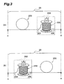
- the optical fiber transmission line 20 may have a construction to function one of the first and second optical fibers 200, 300 as an optical transmission line and arrange the other on the transmission line to be provided as a module.
- the optical fiber transmission line 20 constructed by a fiber module 350 including the first optical fiber 200 and second optical fiber 300 is shown in the area (a) of Fig. 3.
- the fiber module 350 has a container for storing the second optical fiber 300 wound at a diameter d.
- This container is provided with a connector 305 for connecting optically a signal input end of the second optical fiber 300 and a signal output end of the first optical fiber 200, and a connector 306 for connecting optically a signal output end of the second optical fiber 300 and a signal input end of a receiving station 20.
- an optical fiber transmission line 20 constructed by a fiber module 250 including a first optical fiber 200 and a second optical fiber 300 is shown in the area (b) of Fig. 3.
- the fiber module 250 has a container for storing the first optical fiber 200 wound at d in diameter. This container is provided with a connector 205 for connecting optically a signal input end of the first optical fiber 200 and a signal output end of a transmitting station, and a connector 206 for connecting optically a signal output end of the first optical fiber 200 and a signal input end of the second optical fiber 300.
- chromatic dispersion can be performed by a refractive index profile as shown in the area (b) of Fig. 4.
- Fig. 4 is a view illustrating a sectional structure from a typical structure of an optical fiber according to the present invention and its refractive index profile.
- first and second optical fibers 200, 300 each have a core region 21, and a cladding region 22 provided on an outer periphery of the core region 21 and having a refractive index of n 4 .
- the core region 21 comprises: a first core 21a extending along a predetermined axis, having an outer diameter 2a and having a refractive index n 1 (> n 4 ); a second core 21b provided on an outer periphery of the first core 21a, having an outer diameter 2b and having a refractive index n 2 ( ⁇ n 1 , n 4 ); and a third core 21c provided on an outer periphery of the first core 21 b, having an outer diameter 2c and having a refractive index n 3 ( ⁇ n 1 , > n 2 , n 4 ).
- a relative refractive index difference ⁇ + of the first core 21a, a relative refractive index difference ⁇ - of the second core 21b, and a relative refractive index difference ⁇ r of the third core 21c with respect to the cladding region 22 are provided with the following equations.
- Equation 2 ⁇ + ⁇ ( n 1 ⁇ n 4 ) / n 1 ⁇ 100 ⁇ ⁇ ⁇ ( n 2 ⁇ n 4 ) / n 2 ⁇ 100 ⁇ r ⁇ ( n 3 ⁇ n 4 ) / n 3 ⁇ 100
- a refractive profile 290 of an optical fiber corresponding to each of the first and second optical fibers 200, 300 shown in the area (a) of Fig. 4 is shown in the area (b) of Fig. 4.
- a region 291 represents a refractive index at each area on line L of the first core 21 a
- a region 292 represents a refractive index at each area on line L of the first core 21b
- a region 293 represents a refractive index at each area on line L of the third core 21c
- a region 294 represents a refractive index at each area on line L of the cladding region 22.
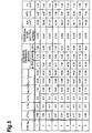
- Fig. 5 is a table listing specifications for nine types of optical fibers as the samples for the optical fiber according to the present invention.
- optical fibers of Types 1 to 5 are samples for the first optical fiber 200 having a positive chromatic dispersion in the wavelength range of 1460 nm to 1620 nm
- optical fibers of Types 6 to 9 are samples for the second optical fiber 300 having a negative chromatic dispersion in the wavelength range.
- all the optical fibers of Types 1 to 9 corresponding to any one of the first and second optical fibers 200, 300 have a sectional structure and refractive index profile shown in Fig. 4.
- the optical fiber of Type 1 corresponds to the first optical fiber 200, the outer diameter 2a of the first core is 7.92 ⁇ m, the outer diameter 2b of the second core is 12.29 ⁇ m, and the outer diameter of the third core is 18.20 ⁇ m.
- the relative refractive index difference ⁇ + of the first core is 0.65 %
- the relative refractive index difference ⁇ - of the second core is -0.7 %
- the relative refractive index difference ⁇ r of the third core is 0.3 %.
- this optical fiber of Type 1 has a chromatic dispersion of 7.74 ps/nm/km, a dispersion slope of -0.002 ps/nm 2 /km, and an effective area A eff of 37.55 ⁇ m 2 , and a mode field diameter MFD of 6.87 ⁇ m. Additionally, the optical fiber of Type 1 has the chromatic dispersions of 6.71 ps/nm/km and 7.09 ps/nm/km at the wavelengths of 1460 nm and 1630 nm, respectively. Then, the cutoff wavelength ⁇ c is 1.41 ⁇ m.
- the optical fiber of Type 2 corresponds to the first optical fiber 200, the outer diameter 2a of the first core is 7.97 ⁇ m, the outer diameter 2b of the second core is 13.54 ⁇ m, and the outer diameter of the third core is 19.20 ⁇ m.
- the relative refractive index difference ⁇ + of the first core is 0.65 %
- the relative refractive index difference ⁇ - of the second core is -0.5 %
- the relative refractive index difference ⁇ r of the third core is 0.3 %.
- this optical fiber of Type 2 has a chromatic dispersion of 8.38 ps/nm/km, a dispersion slope of 0.007 ps/nm 2 /km, and an effective area A eff of 38.06 ⁇ m 2 , and a mode field diameter MFD of 6.97 ⁇ m. Additionally, the optical fiber of Type 2 has the chromatic dispersions of 6.67 ps/nm/km and 8.40 ps/nm/km at the wavelengths of 1460 nm and 1630 nm, respectively. Then, the cutoff wavelength ⁇ c is 1.40 ⁇ m.
- the optical fiber of Type 3 also corresponds to the first optical fiber 200, the outer diameter 2a of the first core is 6.66 ⁇ m, the outer diameter 2b of the second core is 16.98 ⁇ m, and the outer diameter of the third core is 22.20 ⁇ m.
- the relative refractive index difference ⁇ + of the first core is 0.77 %
- the relative refractive index difference ⁇ - of the second core is -0.3 %
- the relative refractive index difference ⁇ r of the third core is 0.3 %.
- this optical fiber of Type 3 has a chromatic dispersion of 8.53 ps/nm/km, a dispersion slope of 0.024 ps/nm 2 /km, and an effective area A eff of 31.37 ⁇ m 2 , and a mode field diameter MFD of 6.43 ⁇ m. Additionally, the optical fiber of Type 3 has the chromatic dispersions of 5.32 ps/nm/km and 9.64 ps/nm/km at the wavelengths of 1460 nm and 1630 nm, respectively. Then, the cutoff wavelength ⁇ c is 1.44 ⁇ m.
- the optical fiber of Type 4 also corresponds to the first optical fiber 200, the outer diameter 2a of the first core is 8.42 ⁇ m, the outer diameter 2b of the second core is 13.96 ⁇ m, and the outer diameter of the third core is 19.80 ⁇ m.
- the relative refractive index difference ⁇ + of the first core is 0.57 %
- the relative refractive index difference ⁇ - of the second core is -0.5 %
- the relative refractive index difference ⁇ r of the third core is 0.3 %.
- this optical fiber of Type 4 has a chromatic dispersion of 8.06 ps/nm/km, a dispersion slope of 0.003 ps/nm 2 /km, and an effective area A eff of 43.84 ⁇ m 2 , and a mode field diameter MFD of 7.44 ⁇ m. Additionally, the optical fiber of Type 4 has the chromatic dispersions of 6.71 ps/nm/km and 7.79 ps/nm/km at the wavelengths of 1460 nm and 1630 nm, respectively. Then, the cutoff wavelength ⁇ c is 1.46 ⁇ m.
- the optical fiber of Type 5 also corresponds to the first optical fiber 200, the outer diameter 2a of the first core is 8.42 ⁇ m, the outer diameter 2b of the second core is 13.96 ⁇ m, and the outer diameter of the third core is 19.80 ⁇ m.
- the relative refractive index difference ⁇ + of the first core is 0.54 %
- the relative refractive index difference ⁇ - of the second core is -0.5 %
- the relative refractive index difference ⁇ r of the third core is 0.3 %.
- this optical fiber of Type 5 has a chromatic dispersion of 8.35 ps/nm/km, a dispersion slope of 0.002 ps/nm 2 /km, and an effective area A eff of 45.47 ⁇ m 2 , and a mode field diameter MFD of 7.57 ⁇ m. Additionally, the optical fiber of Type 5 has the chromatic dispersions of 7.04 ps/nm/km and 8.00 ps/nm/km at the wavelengths of 1460 nm and 1630 nm, respectively. Then, the cutoff wavelength ⁇ c is 1.48 ⁇ m.
- the optical fiber of Type 6 corresponds to the second optical fiber 300
- the outer diameter 2a of the first core is 6.83 ⁇ m
- the outer diameter 2b of the second core is 10.21 ⁇ m
- the outer diameter of the third core is 16.08 ⁇ m.
- the relative refractive index difference ⁇ + of the first core is 0.76 %
- the relative refractive index difference ⁇ - of the second core is -0.7 %
- the relative refractive index difference ⁇ r of the third core is 0.3 %.
- this optical fiber of Type 6 has a chromatic dispersion of -7.95 ps/nm/km, a dispersion slope of -0.021 ps/nm 2 /km, and an effective area A eff of 35.24 ⁇ m 2 , and a mode field diameter MFD of 6.65 ⁇ m. Additionally, the optical fiber of Type 6 has the chromatic dispersions of -6.28 ps/nm/km and -9.22 ps/nm/km at the wavelengths of 1460 nm and 1630 nm, respectively. Then, the cutoff wavelength ⁇ c is 1.39 ⁇ m.
- the optical fiber of Type 7 corresponds to the second optical fiber 300, the outer diameter 2a of the first core is 6.64 ⁇ m, the outer diameter 2b of the second core is 10.87 ⁇ m, and the outer diameter of the third core is 16.52 ⁇ m.
- the relative refractive index difference ⁇ + of the first core is 0.77 %
- the relative refractive index difference ⁇ - of the second core is -0.5 %
- the relative refractive index difference ⁇ r of the third core is 0.3 %.
- this optical fiber of Type 7 has a chromatic dispersion of -7.92 ps/nm/km, a dispersion slope of -0.019 ps/nm 2 /km, and an effective area A eff of 35.11 ⁇ m 2 , and a mode field diameter MFD of 6.69 ⁇ m. Additionally, the optical fiber of Type 7 has the chromatic dispersions of -6.52 ps/nm/km and -9.06 ps/nm/km at the wavelengths of 1460 nm and 1630 nm, respectively. Then, the cutoff wavelength ⁇ c is 1.40 ⁇ m.
- the optical fiber of Type 8 also corresponds to the second optical fiber 300, the outer diameter 2a of the first core is 6.18 ⁇ m, the outer diameter 2b of the second core is 12.27 ⁇ m, and the outer diameter of the third core is 17.40 ⁇ m.
- the relative refractive index difference ⁇ + of the first core is 0.81 %
- the relative refractive index difference ⁇ - of the second core is -0.3 %
- the relative refractive index difference ⁇ r of the third core is 0.3 %.
- this optical fiber of Type 8 has a chromatic dispersion of -7.79 ps/nm/km, a dispersion slope of -0.020 ps/nm 2 /km, and an effective area A eff of 33.17 ⁇ m 2 , and a mode field diameter MFD of 6.58 ⁇ m. Additionally, the optical fiber of Type 8 has the chromatic dispersions of -6.70 ps/nm/km and -9.28 ps/nm/km at the wavelengths of 1460 nm and 1630 nm, respectively. Then, the cutoff wavelength ⁇ c is 1.39 ⁇ m.
- the optical fiber of Type 9 also corresponds to the second optical fiber 300, the outer diameter 2a of the first core is 7.13 ⁇ m, the outer diameter 2b of the second core is 11.53 ⁇ m, and the outer diameter of the third core is 17.60 ⁇ m
- the relative refractive index difference ⁇ + of the first core is 0.69 %
- the relative refractive index difference ⁇ - of the second core is -0.5 %
- the relative refractive index difference ⁇ r of the third core is 0.3 %.
- this optical fiber of Type 9 has a chromatic dispersion of -7.75 ps/nm/km, a dispersion slope of -0.016 ps/nm 2 /km, and an effective area A eff of 40.52 ⁇ m 2 , and a mode field diameter MFD of 7.11 ⁇ m. Additionally, the optical fiber of Type 9 has the chromatic dispersions of -6.25 ps/nm/km and -8.47 ps/nm/km at the wavelengths of 1460 nm and 1630 nm, respectively. Then, the cutoff wavelength ⁇ c is 1.48 ⁇ m.
- the relative refractive index difference ⁇ - of the second core 21b with respect to the cladding region 22 is -0.7 % or more but -0.3 % or less.
- an effective area A eff of 43 ⁇ m 2 or more is provided at the wavelength of 1550 nm, and the relative refractive index difference ⁇ + of the first core 21 a with respect to the cladding region 22 is 0.5 % or more but 0.6 % or less.
- these optical fibers of Types 1 to 9 each have a transmission loss of 0.21 dB/km or less, a micro-bending loss of 10 dB/m or less when it is bent at a diameter of 20 mm, and a polarization mode dispersion of 0.25 dB ⁇ km -1/2 or less at the wavelength of 1550 nm.
- an optical fiber transmission line applicable to the optical transmission system according to the present invention can be constructed by a line component unit that comprises a pair of first and second optical fibers having the aforementioned structure
- this optical fiber transmission line may include a plurality of line components each having the same structure as that of the above-described line component.
- the first optical fiber 200 included in each of the plurality of line components preferably has a mode field diameter of 7.5 ⁇ m to 8.5 ⁇ m in the above-described wavelength range.
- the invention is applied to an optical transmission system that enables to reduce variations between wavelengths in chromatic dispersion over a wide wavelength range, and suppress non-linear optical effects.
Landscapes
- Chemical & Material Sciences (AREA)
- Dispersion Chemistry (AREA)
- Physics & Mathematics (AREA)
- General Physics & Mathematics (AREA)
- Optics & Photonics (AREA)
- Nonlinear Science (AREA)
- Electromagnetism (AREA)
- Engineering & Computer Science (AREA)
- Computer Networks & Wireless Communication (AREA)
- Signal Processing (AREA)
- Optical Communication System (AREA)
- Optical Fibers, Optical Fiber Cores, And Optical Fiber Bundles (AREA)
Abstract
The present invention provides an optical transmission system and so on having a structure that enables to reduce variations between wavelengths in chromatic dispersion over a wide wavelength range and control non-linear optical effects.
An optical fiber transmission line comprises a first optical fiber having a positive chromatic dispersion such that its wavelength dependence is reduced over a wide wavelength range, and a second optical fiber having a negative chromatic dispersion such that its wavelength dependence is reduced over the wavelength range. In this way, the first and second optical fibers each have a chromatic dispersion of a different polarity, thereby controlling accumulated chromatic dispersions at low level for a whole optical fiber transmission line, while the chromatic dispersion occurs to some extent in each of the first and second optical fibers, thereby controlling effectively non-linear optical effects such as four-wave mixing.
Description
- The present invention relates to an optical fiber, an optical fiber transmission line, and an optical transmission system that are available as an optical transmission line suitable for to an optical transmission for wavelength division multiplexing (WDM).
- A WDM optical transmission system is the one that transmits signal light involving a plurality of channels having different wavelengths from each other by way of an optical fiber as a transmission line, and that enables an information transmission of high speed and large capacity. Typically, a transmission fiber is an optical fiber mainly composed of silica and having the smallest transmission loss with respect to light in the 1.55 µm wavelength band. In the WDM transmission system having such an optical fiber as an optical transmission line, signal light in the 1.55 µm wavelength band is used. On the other hand, a standard single mode optical fiber having a zero dispersion wavelength in the 1.3 µm wavelength band has a positive chromatic dispersion in the 1.55 µm wavelength band. The chromatic dispersion depends greatly on wavelengths, while a waveform of the signal light is deteriorated easily when the chromatic dispersion is large. In addition, the waveform of the signal light is further deteriorated due to an interaction between the chromatic dispersion and non-linear optical phenomena.
- Thus, for a conventional optical transmission system, the following dispersion flattened fiber is proposed: wavelength dependence of chromatic dispersions is reduced over a wide wavelength range, while an absolute value of the chromatic dispersions is controlled at low level, thereby suppressing waveform distortion of signal light caused by the chromatic dispersions (for instance, see Patent Documents).
Patent Document 1: U. S. Patent No. 6,169,837 B1
Patent Document 2: Japanese Patent Application Laid-Open No. 8-248251 (EP 0 724 171 A2) - The inventors have studied a conventional optical transmission system and a dispersion flattened fiber applied thereto in detail, and as a result, have found problems as follows.
- Thus, in the WDM optical transmission, for the purpose of achieving further high-speed signal transmission, and large capacity development of information transmission, it is necessary to bring as small as possible an absolute value of an accumulated chromatic dispersion in a transmission line over a wider wavelength range. Therefore, a conventional dispersion flattened fiber is designed so that an absolute value of its chromatic dispersion is approximated to zero as nearly as possible.
- However, when multiplexed WDM signal light having a plurality of channels is transmitted, in a conventional dispersion flattened fiber designed so that the absolute value of its chromatic dispersion is approximated to zero more closely, there may occur easily a non-linear optical effect, particularly four-wave mixing, resulting in providing a factor to deteriorate transmission characteristics in a whole optical fiber transmission line.
- The present invention is made to solve the aforementioned problems, and it is an object to provide an optical transmission system having a structure to reduce variations between wavelengths in chromatic dispersion over a wider wavelength range and also suppress effectively a non-linear optical effect such as four-wave mixing, and to provide an optical fiber and an optical fiber transmission line applicable to this system.
- An optical transmission system according to the present invention includes an optical fiber transmission line for transmitting signal light having a plurality of channels having different wavelengths from each other, and then this optical fiber transmission line comprises at least one pair of optical fibers having chromatic dispersions having different polarities from each other in the wavelength range of 1460 nm to 1620 nm.
- In particular, optical fibers having chromatic dispersions having different signs from each other are included in the optical transmission system; with respect to any one of the optical fibers, in the wavelength range of 1460 nm to 1620 nm, the optical fiber having a chromatic dispersion whose absolute value is 5 ps/nm/km or more but 10 ps/nm/km or less and an optical property of 4 ps/nm/km or less in a difference between a maximum value and a minimum value of the chromatic dispersion in the same wavelength range, is applicable. Thus, a first optical fiber applicable as a part of the optical fiber transmission line has a dispersion versus wavelength characteristic of an upwardly convex shape in the wavelength range of 1460 to 1620 nm, and has a positive chromatic dispersion, while a second optical fiber applicable as a part of the optical fiber transmission line has a dispersion versus wavelength characteristic of an downwardly convex shape in the wavelength range, and has a negative chromatic dispersion. Specifically, the first optical fiber has a chromatic dispersion of +5 ps/nm/km or more but +10 ps/nm/km or less in the wavelength range and an optical property of 4 ps/nm/km or less in a difference between a maximum value and a minimum value of the chromatic dispersion in the wavelength range. On the other hand, the second optical fiber has a chromatic dispersion of -10 ps/nm/km or more but -5 ps/nm/km or less in the wavelength range and optical property of 4 ps/nm/km or less in a difference between a maximum value and a minimum value of the chromatic dispersion in the wavelength range. In addition, in order to reduce wavelength dependence of the chromatic dispersion, both the first and second optical fibers preferably has a dispersion slope whose absolute value is 0.02 ps/nm2/km or less at the wavelength of 1550 nm.
- As described above, the optical fiber transmission line (optical fiber transmission line according to the present invention) composes optical fibers having different chromatic dispersions in polarity from each other, and these optical fibers (optical fiber according to the present invention) have a larger chromatic dispersion as compared with conventional flattened fibers, while they have a smaller chromatic dispersion as compared with standard single mode optical fibers. That is, the optical fiber according to the present invention, optical fiber transmission line including the optical fiber, and further optical transmission system including the optical fiber transmission line each can reduce distortion of signal waveforms caused by an occurrence of the chromatic dispersion as compared with standard single mode optical fibers, and can also reduce wavelength dependence of the chromatic dispersion to be occurred, thereby being of extremely great value to be used as a wide range WDM optical transmission system.
- In addition, in the aforementioned first and second optical fibers, in order to reduce the wavelength dependence of the chromatic dispersion more efficiently, a difference between the chromatic dispersion at the wavelength of 1460 nm (lower limit wavelength of the wavelength range) and that at the wavelength of 1620 nm (upper limit wavelength of the wavelength range) is preferably 1 ps/nm/km or less.
- Each of the first and second optical fibers comprises a core region extending along a predetermined axis and a cladding region provided on an outer periphery of the core region. In particular, the core region is constructed by: a first core extending a predetermined axis, the first core region having an
outer diameter 2a and a maximum refractive index n1; a second core provided on an outer periphery of the first core, the second core region having anouter diameter 2b and a refractive index of n2 lower than that of the first core; and a third core provided on an outer periphery of the second core, the third core region having anouter diameter 2c and a refractive index of n3 higher than that of the second core. The cladding region is provided on an outer periphery of the third core, and has a refractive index of n4 lower than that of the third core. - In the first and second optical fibers having the aforementioned structure, the upper limit of a relative refractive index difference Δ- of the second core with respect to the cladding region is preferably -0.3 % or less. On the other hand, the lower limit of the relative refractive index difference Δ- of the second core with respect to the cladding region is preferably -0.7 % or more. In addition, preferably, the first optical fiber has an effective area Aeff 43 µm2 or more at the wavelength of 1550 nm, and a relative refractive index difference Δ+ of the first core with respect to the cladding region is 0.5 % or more but 0.6 % or less. On the other hand, preferably, the second optical fiber has an effective area Aeff of 35 µm2 or more at the wavelength of 1550 nm, and a relative refractive index difference Δ+ of the first core with respect to the cladding region is 0.65 % or more but 0.80 % or less.
- Note that as shown in
Patent Document 2, the effective area Aeff is provided by the following equation:
- where E is the electric field involved in propagation light, and r is the distance in a radius direction from the center of the core.
- Further, the first optical fiber preferably has a mode field diameter of 7.5 µm to 8.5 µm at the wavelength range, preferably at the wavelength of 1550 nm.
- Though an optical fiber transmission line applicable to the optical transmission system according to the present invention can be constructed by a line component unit that composes a pair of first and second optical fibers having the aforementioned structure, this optical fiber transmission line may include a plurality of line components each having the same structure as that of the above-described line component. In this case, the first optical fiber included in each of the plurality of line components preferably has a mode field diameter of 7.5µm to 8.5 µm in the wavelength range. Thus, deterioration of transmission characteristics caused by non-linear optical effects is effectively suppressed since it is possible to reduce an optical power density of propagating signal light. In addition, the optical fiber transmission line constructed by the plurality of line components may have a configuration to be arranged such that the first optical fibers included in the plurality of line components are arranged to be adjacent to each other, and that the second optical fibers included in the plurality of line components are arranged to be adjacent to each other. Thus, deterioration of transmission characteristics caused by non-linear optical effects is effectively suppressed by controlling the number of changes in polarity of the chromatic dispersion to be occurred along the longitudinal direction of the optical fiber transmission line.
- As described above, in accordance with the present invention, the optical fiber transmission line comprising the first optical fiber having a positive chromatic dispersion such that its wavelength dependence is reduced over a wide wavelength range of 1460 nm to 1620 nm, and the second optical fiber having a negative chromatic dispersion such that its wavelength dependence is reduced over the wavelength range. In this way, each of the first and second optical fibers has a chromatic dispersion of a different polarity, thereby controlling accumulated chromatic dispersion at low level for a whole optical fiber transmission line, while the chromatic dispersion occurs to some extent in each of the first and second optical fibers, thereby controlling effectively non-linear optical effects such as four-wave mixing.
- Fig. 1 is a diagram showing the constructions of an optical transmission system, a transmitting station, and a receiving station according to the present invention;
- Fig. 2 is a diagram for explaining constructions of optical fiber transmission lines and chromatic dispersion characteristics in the optical transmission system according to the present invention;
- Fig. 3 is a diagram for explaining other constructions of the optical fiber transmission lines in the optical transmission system according to the present invention;
- Fig. 4 illustrates a sectional structure for explaining a typical structure of an optical fiber and its refractive index profile according to the present invention; and
- Fig. 5 is a table listing specifications for the plurality of samples (samples No. 1 to No. 9) with respect to the optical fiber according to the present invention.
- 10...transmitting station; 20...optical fiber transmission line; 30...receiving station; 11a to 11n...transmitter; 12...multiplexer; 31...demultiplexer; 100...optical fiber; 110...core region; 120...cladding region; 32a to 32n...receiver; and 250, 350...fiber module.
- In the following, the best modes for carrying out the inventions will be explained in detail with reference to Figs. 1-5. In the explanation of the drawings, the same elements will be denoted by the same reference symbols and these redundant descriptions will be omitted.
- Fig. 1 is a diagram showing the constructions of an optical transmission system, a transmitting station, and a receiving station according to the present invention. The optical transmission system, shown in the area (a) of Fig. 1, composes a
transmitting station 10 for transmitting signal light, an opticalfiber transmission line 20 as a transmission medium through which the signal light propagates, and areceiving station 30 for receiving the signal light. A signal input end A of the opticalfiber transmission line 20 is connected to a signal output end of thetransmitting station 10, while a signal output end B of the opticalfiber transmission line 20 is connected to the signal input end of thereceiving station 30. - As shown in the area (b) of Fig. 1, the
transmitting station 10 comprises light sources (Tx1 to TXn) 11a to 11n for emitting light beams having wavelengths λ1 to λn respectively, and amultiplexer 12 for multiplexing the light beams having the wavelengths λ1 to λn emitted from thelight sources 11a to 11n, and outputs the signal light (WDM signal light), where signal channels of the wavelengths λ1 to λn are multiplexed, toward the opticalfiber transmission line 20. - As shown in the area (c) of Fig. 1, the
receiving station 30 comprises ademultiplexer 31 for demultiplexing the signal channels of the wavelengthsλ1 to λn contained in the WDM signal light which propagates through theoptical transmission line 20, and optical receivers (RX1 to RXn) 32a to 32n for receiving the light beams having the wavelengthsλ1 to λn and demultiplexed by thedemultiplexer 31 respectively. - In the optical transmission system according to the present invention, the optical
fiber transmission line 20 is constructed by at least one pair of optical fibers having chromatic dispersions having different polarities from each other in a wavelength range of 1460 nm to 1620 nm. For example, as shown in the area (a) of Fig. 2, thetransmission line 20 has a structure such that a firstoptical fiber 200 having a positive chromatic dispersion in the wavelength range of 1460 nm to 1620 nm is fusion-spliced with a secondoptical fiber 300 having a negative chromatic dispersion in the wavelength range. Each of theoptical fibers - That is, as shown by graph G210 in the area (c) of Fig. 2, the first
optical fiber 200 has a dispersion versus wavelength characteristic of an upwardly convex shape in the wavelength range. Specifically, the firstoptical fiber 200 has a positive chromatic dispersion of +5 ps/nm/km to +10 ps/nm/km in the wavelength range, and an optical property of 4 ps/nm/km or less in a difference between the maximum value and the minimum value of the chromatic dispersion in the wavelength range. On the other hand, as shown by graph G220 in the area (c) of Fig. 2, the secondoptical fiber 300 has a dispersion versus wavelength characteristic in a downwardly convex shape. Specifically, the secondoptical fiber 300 has a chromatic dispersion of -10 ps/nm/km or more but -5 ps/nm/km or less in the wavelength range, and an optical property of 4 ps/nm/km or less in a difference between the maximum value and the minimum value of the chromatic dispersion in the wavelength range. In order to reduce wavelength dependency in the chromatic dispersion, each of the first and secondoptical fibers - As described above, the optical
fiber transmission line 20 comprises the first and secondoptical fibers second fibers fiber transmission line 20 constructed by the first and secondoptical fibers fiber transmission line 20 having the aforementioned characteristics of chromatic dispersion can reduce distortion caused by an occurrence of the chromatic dispersion as compared with standard single mode optical fibers (accumulated chromatic dispersion viewed from the whole optical fiber transmission line is small), and can also reduce wavelength dependency of occurred chromatic dispersions, which enables usage as a wide-band WDM optical transmission system. - In addition, in the aforementioned first and second
optical fibers fiber transmission line 20 has a chromatic dispersion of 1 ps/nm/km or less in the range of 1460 nm to 1620 nm. - Further, as shown in the area (a) of Fig. 2, it is possible to construct the optical
fiber transmission line 20 by a pair of the first and secondoptical fibers 200, 300 (line components), each of which may contain a plurality of line components having the same structure as that of such a line component. In this case, as shown in the area (b) of Fig. 2, the opticalfiber transmission lien 20 may also be arranged such that firstoptical fibers optical fibers fiber transmission line 20. - In the optical transmission system according to the present invention, as shown in Fig. 3, the optical
fiber transmission line 20 may have a construction to function one of the first and secondoptical fibers - For example, the optical
fiber transmission line 20 constructed by afiber module 350 including the firstoptical fiber 200 and secondoptical fiber 300 is shown in the area (a) of Fig. 3. In the opticalfiber transmission line 20 in the area (a) of Fig. 3, thefiber module 350 has a container for storing the secondoptical fiber 300 wound at a diameter d. This container is provided with aconnector 305 for connecting optically a signal input end of the secondoptical fiber 300 and a signal output end of the firstoptical fiber 200, and aconnector 306 for connecting optically a signal output end of the secondoptical fiber 300 and a signal input end of a receivingstation 20. - On the other hand, an optical
fiber transmission line 20 constructed by afiber module 250 including a firstoptical fiber 200 and a secondoptical fiber 300 is shown in the area (b) of Fig. 3. In the opticalfiber transmission line 20 in the area (b) of Fig. 3, thefiber module 250 has a container for storing the firstoptical fiber 200 wound at d in diameter. This container is provided with aconnector 205 for connecting optically a signal input end of the firstoptical fiber 200 and a signal output end of a transmitting station, and aconnector 206 for connecting optically a signal output end of the firstoptical fiber 200 and a signal input end of the secondoptical fiber 300. - The aforementioned characteristics of chromatic dispersion can be performed by a refractive index profile as shown in the area (b) of Fig. 4.
- Fig. 4 is a view illustrating a sectional structure from a typical structure of an optical fiber according to the present invention and its refractive index profile. As shown in the area (a) of Fig. 4, first and second
optical fibers core region 21, and acladding region 22 provided on an outer periphery of thecore region 21 and having a refractive index of n4. In particular, thecore region 21 comprises: afirst core 21a extending along a predetermined axis, having anouter diameter 2a and having a refractive index n1 (> n4); asecond core 21b provided on an outer periphery of thefirst core 21a, having anouter diameter 2b and having a refractive index n2 (< n1, n4); and athird core 21c provided on an outer periphery of thefirst core 21 b, having anouter diameter 2c and having a refractive index n3 (< n1, > n2, n4). - For instance, when the
cladding region 22 is provided as a reference region, a relative refractive index difference Δ+ of thefirst core 21a, a relative refractive index difference Δ- of thesecond core 21b, and a relative refractive index difference Δr of thethird core 21c with respect to thecladding region 22 are provided with the following equations.


- A
refractive profile 290 of an optical fiber corresponding to each of the first and secondoptical fibers refractive index profile 290, aregion 291 represents a refractive index at each area on line L of thefirst core 21 a, aregion 292 represents a refractive index at each area on line L of thefirst core 21b, aregion 293 represents a refractive index at each area on line L of thethird core 21c, and aregion 294 represents a refractive index at each area on line L of thecladding region 22. - A sample of the optical fiber according to the present invention will next be described below. Fig. 5 is a table listing specifications for nine types of optical fibers as the samples for the optical fiber according to the present invention. In particular, optical fibers of
Types 1 to 5 are samples for the firstoptical fiber 200 having a positive chromatic dispersion in the wavelength range of 1460 nm to 1620 nm, and optical fibers ofTypes 6 to 9 are samples for the secondoptical fiber 300 having a negative chromatic dispersion in the wavelength range. In addition, all the optical fibers ofTypes 1 to 9 corresponding to any one of the first and secondoptical fibers - The optical fiber of
Type 1 corresponds to the firstoptical fiber 200, theouter diameter 2a of the first core is 7.92 µm, theouter diameter 2b of the second core is 12.29 µm, and the outer diameter of the third core is 18.20 µm. With respect to the cladding region as a reference region, the relative refractive index difference Δ+ of the first core is 0.65 %, the relative refractive index difference Δ- of the second core is -0.7 %, and the relative refractive index difference Δr of the third core is 0.3 %. Further, for a variety of characteristics at the wavelength of 1550 nm, this optical fiber ofType 1 has a chromatic dispersion of 7.74 ps/nm/km, a dispersion slope of -0.002 ps/nm2/km, and an effective area Aeff of 37.55 µm2, and a mode field diameter MFD of 6.87 µm. Additionally, the optical fiber ofType 1 has the chromatic dispersions of 6.71 ps/nm/km and 7.09 ps/nm/km at the wavelengths of 1460 nm and 1630 nm, respectively. Then, the cutoff wavelength λc is 1.41 µm. - The optical fiber of
Type 2 corresponds to the firstoptical fiber 200, theouter diameter 2a of the first core is 7.97 µm, theouter diameter 2b of the second core is 13.54 µm, and the outer diameter of the third core is 19.20 µm. With respect to the cladding region as a reference region, the relative refractive index difference Δ+ of the first core is 0.65 %, the relative refractive index difference Δ- of the second core is -0.5 %, and the relative refractive index difference Δr of the third core is 0.3 %. Further, for a variety of characteristics at the wavelength of 1550 nm, this optical fiber ofType 2 has a chromatic dispersion of 8.38 ps/nm/km, a dispersion slope of 0.007 ps/nm2/km, and an effective area Aeff of 38.06 µm2, and a mode field diameter MFD of 6.97 µm. Additionally, the optical fiber ofType 2 has the chromatic dispersions of 6.67 ps/nm/km and 8.40 ps/nm/km at the wavelengths of 1460 nm and 1630 nm, respectively. Then, the cutoff wavelength λc is 1.40 µm. - The optical fiber of
Type 3 also corresponds to the firstoptical fiber 200, theouter diameter 2a of the first core is 6.66 µm, theouter diameter 2b of the second core is 16.98 µm, and the outer diameter of the third core is 22.20 µm. With respect to the cladding region as a reference region, the relative refractive index difference Δ+ of the first core is 0.77 %, the relative refractive index difference Δ- of the second core is -0.3 %, and the relative refractive index difference Δr of the third core is 0.3 %. Further, for a variety of characteristics at the wavelength of 1550 nm, this optical fiber ofType 3 has a chromatic dispersion of 8.53 ps/nm/km, a dispersion slope of 0.024 ps/nm2/km, and an effective area Aeff of 31.37 µm2, and a mode field diameter MFD of 6.43 µm. Additionally, the optical fiber ofType 3 has the chromatic dispersions of 5.32 ps/nm/km and 9.64 ps/nm/km at the wavelengths of 1460 nm and 1630 nm, respectively. Then, the cutoff wavelength λc is 1.44 µm. - The optical fiber of
Type 4 also corresponds to the firstoptical fiber 200, theouter diameter 2a of the first core is 8.42 µm, theouter diameter 2b of the second core is 13.96 µm, and the outer diameter of the third core is 19.80 µm. With respect to the cladding region as a reference region, the relative refractive index difference Δ+ of the first core is 0.57 %, the relative refractive index difference Δ- of the second core is -0.5 %, and the relative refractive index difference Δr of the third core is 0.3 %. Further, for a variety of characteristics at the wavelength of 1550 nm, this optical fiber ofType 4 has a chromatic dispersion of 8.06 ps/nm/km, a dispersion slope of 0.003 ps/nm2/km, and an effective area Aeff of 43.84 µm2, and a mode field diameter MFD of 7.44 µm. Additionally, the optical fiber ofType 4 has the chromatic dispersions of 6.71 ps/nm/km and 7.79 ps/nm/km at the wavelengths of 1460 nm and 1630 nm, respectively. Then, the cutoff wavelength λc is 1.46 µm. - Further, the optical fiber of
Type 5 also corresponds to the firstoptical fiber 200, theouter diameter 2a of the first core is 8.42 µm, theouter diameter 2b of the second core is 13.96 µm, and the outer diameter of the third core is 19.80 µm. With respect to the cladding region as a reference region, the relative refractive index difference Δ+ of the first core is 0.54 %, the relative refractive index difference Δ- of the second core is -0.5 %, and the relative refractive index difference Δr of the third core is 0.3 %. Further, for a variety of characteristics at the wavelength of 1550 nm, this optical fiber ofType 5 has a chromatic dispersion of 8.35 ps/nm/km, a dispersion slope of 0.002 ps/nm2/km, and an effective area Aeff of 45.47 µm2, and a mode field diameter MFD of 7.57 µm. Additionally, the optical fiber ofType 5 has the chromatic dispersions of 7.04 ps/nm/km and 8.00 ps/nm/km at the wavelengths of 1460 nm and 1630 nm, respectively. Then, the cutoff wavelength λc is 1.48 µm. - On the other hand, the optical fiber of
Type 6 corresponds to the secondoptical fiber 300, theouter diameter 2a of the first core is 6.83 µm, theouter diameter 2b of the second core is 10.21 µm, and the outer diameter of the third core is 16.08 µm. With respect to the cladding region as a reference region, the relative refractive index difference Δ+ of the first core is 0.76 %, the relative refractive index difference Δ- of the second core is -0.7 %, and the relative refractive index difference Δr of the third core is 0.3 %. Further, for a variety of characteristics at the wavelength of 1550 nm, this optical fiber ofType 6 has a chromatic dispersion of -7.95 ps/nm/km, a dispersion slope of -0.021 ps/nm2/km, and an effective area Aeff of 35.24 µm2, and a mode field diameter MFD of 6.65 µm. Additionally, the optical fiber ofType 6 has the chromatic dispersions of -6.28 ps/nm/km and -9.22 ps/nm/km at the wavelengths of 1460 nm and 1630 nm, respectively. Then, the cutoff wavelength λc is 1.39 µm. - The optical fiber of
Type 7 corresponds to the secondoptical fiber 300, theouter diameter 2a of the first core is 6.64 µm, theouter diameter 2b of the second core is 10.87 µm, and the outer diameter of the third core is 16.52 µm. With respect to the cladding region as a reference region, the relative refractive index difference Δ+ of the first core is 0.77 %, the relative refractive index difference Δ- of the second core is -0.5 %, and the relative refractive index difference Δr of the third core is 0.3 %. Further, for a variety of characteristics at the wavelength of 1550 nm, this optical fiber ofType 7 has a chromatic dispersion of -7.92 ps/nm/km, a dispersion slope of -0.019 ps/nm2/km, and an effective area Aeff of 35.11 µm2, and a mode field diameter MFD of 6.69 µm. Additionally, the optical fiber ofType 7 has the chromatic dispersions of -6.52 ps/nm/km and -9.06 ps/nm/km at the wavelengths of 1460 nm and 1630 nm, respectively. Then, the cutoff wavelength λc is 1.40 µm. - The optical fiber of
Type 8 also corresponds to the secondoptical fiber 300, theouter diameter 2a of the first core is 6.18 µm, theouter diameter 2b of the second core is 12.27 µm, and the outer diameter of the third core is 17.40 µm. With respect to the cladding region as a reference region, the relative refractive index difference Δ+ of the first core is 0.81 %, the relative refractive index difference Δ- of the second core is -0.3 %, and the relative refractive index difference Δr of the third core is 0.3 %. Further, for a variety of characteristics at the wavelength of 1550 nm, this optical fiber ofType 8 has a chromatic dispersion of -7.79 ps/nm/km, a dispersion slope of -0.020 ps/nm2/km, and an effective area Aeff of 33.17 µm2, and a mode field diameter MFD of 6.58 µm. Additionally, the optical fiber ofType 8 has the chromatic dispersions of -6.70 ps/nm/km and -9.28 ps/nm/km at the wavelengths of 1460 nm and 1630 nm, respectively. Then, the cutoff wavelength λc is 1.39 µm. - Then, the optical fiber of
Type 9 also corresponds to the secondoptical fiber 300, theouter diameter 2a of the first core is 7.13 µm, theouter diameter 2b of the second core is 11.53 µm, and the outer diameter of the third core is 17.60 µm With respect to the cladding region as a reference region, the relative refractive index difference Δ+ of the first core is 0.69 %, the relative refractive index difference Δ- of the second core is -0.5 %, and the relative refractive index difference Δr of the third core is 0.3 %. Further, for a variety of characteristics at the wavelength of 1550 nm, this optical fiber ofType 9 has a chromatic dispersion of -7.75 ps/nm/km, a dispersion slope of -0.016 ps/nm2/km, and an effective area Aeff of 40.52 µm2, and a mode field diameter MFD of 7.11 µm. Additionally, the optical fiber ofType 9 has the chromatic dispersions of -6.25 ps/nm/km and -8.47 ps/nm/km at the wavelengths of 1460 nm and 1630 nm, respectively. Then, the cutoff wavelength λc is 1.48 µm. - As described above, in the optical fibers of
Types 1 to 9, the relative refractive index difference Δ- of thesecond core 21b with respect to thecladding region 22 is -0.7 % or more but -0.3 % or less. In addition, an effective area Aeff of 43 µm2 or more is provided at the wavelength of 1550 nm, and the relative refractive index difference Δ+ of thefirst core 21 a with respect to thecladding region 22 is 0.5 % or more but 0.6 % or less. Additionally, for other characteristics, these optical fibers ofTypes 1 to 9 each have a transmission loss of 0.21 dB/km or less, a micro-bending loss of 10 dB/m or less when it is bent at a diameter of 20 mm, and a polarization mode dispersion of 0.25 dB · km-1/2 or less at the wavelength of 1550 nm. - Though an optical fiber transmission line applicable to the optical transmission system according to the present invention can be constructed by a line component unit that comprises a pair of first and second optical fibers having the aforementioned structure, this optical fiber transmission line may include a plurality of line components each having the same structure as that of the above-described line component. In this case, the first
optical fiber 200 included in each of the plurality of line components preferably has a mode field diameter of 7.5 µm to 8.5 µm in the above-described wavelength range. Thus, deterioration of transmission characteristics caused by non-linear optical effects is effectively suppressed since it is possible to reduce an optical power density of propagating signal light. - In wavelength division multiplexing optical communication, the invention is applied to an optical transmission system that enables to reduce variations between wavelengths in chromatic dispersion over a wide wavelength range, and suppress non-linear optical effects.
Claims (18)
- An optical fiber having a core region and a cladding region arranged so as to obtain:a chromatic dispersion whose absolute value is 5 ps/nm/km or more but 10 ps/nm/km or less in a wavelength range of 1460 nm to 1620 nm; andan optical property of 4ps/nm/km or less in a difference between a maximum value and a minimum value of the chromatic dispersion in the wavelength range.
- An optical fiber according to claim 1, wherein the chromatic dispersion in the wavelength range of 1460 nm to 1620 nm is +5 ps/nm/km or more but +10 ps/nm/km or less.
- An optical fiber according to claim 1, wherein the chromatic dispersion in the wavelength range of 1460 nm to 1620 nm is -10 ps/nm/km or more but -5 ps/nm/km or less.
- An optical fiber according to any one of claims 1 to 3, wherein a difference between the chromatic dispersion at a wavelength of 1460 nm and the chromatic dispersion at a wavelength of 1620 nm is 1 ps/nm/km or less.
- An optical fiber according to any one of claims 1 to 3, wherein said core region includes: a first core extending along a predetermined axis, said first core region having an outer diameter 2a and a maximum refractive index n1; a second core provided on an outer periphery of said first core, said second core region having an outer diameter 2b and a refractive index n2 lower than that of said first core; and a third core provided on an outer periphery of said second core, said third core region having an outer diameter 2c and a refractive index n3 higher than that of said second core, and
wherein said cladding region is provided on an outer periphery of said third core and has a refractive index n4 lower than that of said third core. - An optical fiber according to claim 5, wherein a relative refractive index difference Δ- of said second core with respect to said cladding region is -0.3 % or less.
- An optical fiber according to claim 6, wherein a relative refractive index difference Δ- of said second core with respect to said cladding region is -0.7 % or more.
- An optical fiber according to claim 2, wherein said core region includes: a first core extending along a predetermined axis, said first core region having an outer diameter 2a and a maximum refractive index n1; a second core provided on an outer periphery of said first core, said second core region having an outer diameter 2b and a refractive index n2 lower than that of said first core; and a third core provided on an outer periphery of said second core, said third core region having an outer diameter 2c and a refractive index n3 higher than that of said second core, and said cladding region being provided on an outer periphery of said third core and having a refractive index n4 lower than that of said third core,
wherein said optical fiber further has an effective area of 43 µm2 or more at a wavelength of 1550 nm, and
wherein a relative refractive index difference Δ+ of said first core with respect to said cladding region is 0.5 % or more but 0.6 % or less. - An optical fiber according to claim 3, wherein said core region includes: a first core extending along a predetermined axis, said first core region having an outer diameter 2a and a maximum refractive index n1; a second core provided on an outer periphery of said first core, said second core region having an outer diameter 2b and a refractive index n2 lower than that of said first core; and a third core provided on an outer periphery of said second core, said third core region having an outer diameter 2c and a refractive index n3 higher than that of said second core, and said cladding region being provided on an outer periphery of said third core and having a refractive index n4 lower than that of said third core,
wherein said optical fiber further has an effective area of 35 µm2 or more at a wavelength of 1550 nm, and
wherein a relative refractive index difference Δ+ of said first core with respect to said cladding region is 0.65 % or more but 0.80 % or less. - An optical fiber according to any one of claims 1 to 3, further having a mode field diameter of 7.5µm to 8.5 µm at a wavelength of 1550 nm.
- An optical transmission system comprising:a first optical fiber having a chromatic dispersion whose absolute value is 5 ps/nm/km or more but 10 ps/nm/km or less in a wavelength range of 1460 nm to 1620 nm, and having an optical property of 4 ps/nm/km or less in a difference between a maximum value and a minimum value of the chromatic dispersion in the wavelength range;a second optical fiber optically connected with said first optical fiber, said second optical fiber having a chromatic dispersion with a inverse sign to said first optical fiber in the wavelength range.
- An optical transmission system according to claim 11, wherein said first optical fiber has a chromatic dispersion of +5 ps/nm/km or more but +10 ps/nm/km or less in the wavelength range of 1460 nm to 1620 nm, and said second optical fiber has a negative chromatic dispersion in the wavelength range.
- An optical transmission system according to claim 11, wherein said first optical fiber has a chromatic dispersion of -10 ps/nm/km or more but -5 ps/nm/km or less in the wavelength range and an optical property of 4 ps/nm/km or less in a difference between a maximum value and a minimum value of the chromatic dispersion of said second optical fiber in the wavelength range, and
wherein said second optical fiber has a positive chromatic dispersion in the wavelength range of 1460 nm to 1620 nm. - An optical fiber transmission line comprising one or more line components each including a first optical fiber and a second optical fiber,
wherein said first optical fiber has a chromatic dispersion of +5 ps/nm/km or more but +10 ps/nm/km or less in a wavelength range of 1460 nm to 1620 nm, and a dispersion slope whose absolute value is 0.02 ps/nm2/km or less, and
wherein said second optical fiber has a chromatic dispersion of -10 ps/nm/km or more but -5 ps/nm/km or less in the wavelength range, and a dispersion slope whose absolute value is 0.02 ps/nm2/km or less, and further has an optical property of 4 ps/nm/km or less in a difference between a maximum value and a minimum value of the chromatic dispersion at a wavelength of 1550 nm. - An optical fiber transmission line according to claim 14,
wherein said first optical fiber has a dispersion versus wavelength characteristic of an upwardly convex shape, and said second optical fiber has a dispersion versus wavelength characteristic of an downwardly convex shape. - An optical fiber transmission line according to claim 14,
wherein said first optical fiber included in each of said line components has a mode field diameter of 7.5 µm to 8.5 µm at the wavelength of 1550 nm. - An optical fiber transmission line according to claim 16,
wherein said first optical fibers included in said line components are arranged so as to be adjacent to each other, and said second optical fibers included in said line components are arranged so as to be adjacent to each other. - An optical fiber transmission line comprising: a first optical fiber having a dispersion versus wavelength characteristic of an upwardly convex shape and a positive chromatic dispersion, and a second optical fiber having a dispersion versus wavelength characteristic of an downwardly convex shape and a negative chromatic dispersion, thereby having a chromatic dispersion whose absolute value is I ps/nm/km or less in the wavelength range of 1460 nm to 1620 nm.
Applications Claiming Priority (2)
| Application Number | Priority Date | Filing Date | Title |
|---|---|---|---|
| JP2003273575A JP2005031581A (en) | 2003-07-11 | 2003-07-11 | Optical fiber, optical fiber transmission line and optical transmission system |
| PCT/JP2004/009840 WO2005006041A1 (en) | 2003-07-11 | 2004-07-09 | Fiberoptics, fiberoptic transmission line and optical transmission system |
Publications (2)
| Publication Number | Publication Date |
|---|---|
| EP1653640A1 true EP1653640A1 (en) | 2006-05-03 |
| EP1653640A4 EP1653640A4 (en) | 2011-07-06 |
Family
ID=34056025
Family Applications (1)
| Application Number | Title | Priority Date | Filing Date |
|---|---|---|---|
| EP04747308A Withdrawn EP1653640A4 (en) | 2003-07-11 | 2004-07-09 | OPTICAL FIBER, OPTICAL FIBER TRANSMISSION LINE, AND OPTICAL TRANSMISSION SYSTEM |
Country Status (4)
| Country | Link |
|---|---|
| US (1) | US20060257085A1 (en) |
| EP (1) | EP1653640A4 (en) |
| JP (1) | JP2005031581A (en) |
| WO (1) | WO2005006041A1 (en) |
Family Cites Families (12)
| Publication number | Priority date | Publication date | Assignee | Title |
|---|---|---|---|---|
| CA1248386A (en) * | 1982-03-11 | 1989-01-10 | Leonard G. Cohen | Quadruple-clad optical fiberguide |
| US5684909A (en) * | 1996-02-23 | 1997-11-04 | Corning Inc | Large effective area single mode optical waveguide |
| PL325278A1 (en) * | 1996-07-01 | 1998-07-20 | Corning Inc | Optical fibre with a sheating containing tantalum admixture |
| JP3320745B2 (en) * | 1997-12-05 | 2002-09-03 | 住友電気工業株式会社 | Dispersion flat optical fiber |
| TW451088B (en) * | 1999-04-16 | 2001-08-21 | Sumitomo Electric Industries | Optical fiber and optical transmission line including the same |
| JP2001166173A (en) * | 1999-12-13 | 2001-06-22 | Sumitomo Electric Ind Ltd | Optical fiber |
| JP5028706B2 (en) * | 2000-05-01 | 2012-09-19 | 住友電気工業株式会社 | Optical fiber and optical transmission system |
| JP2002365462A (en) * | 2001-06-12 | 2002-12-18 | Furukawa Electric Co Ltd:The | Optical communication link |
| FR2828939B1 (en) * | 2001-08-27 | 2004-01-16 | Cit Alcatel | OPTICAL FIBER FOR A WAVELENGTH MULTIPLEXED TRANSMISSION SYSTEM |
| JP2003188822A (en) * | 2001-10-10 | 2003-07-04 | Furukawa Electric Co Ltd:The | Optical transmission line and optical transmission system using the optical transmission line |
| JP2003255169A (en) * | 2002-03-04 | 2003-09-10 | Furukawa Electric Co Ltd:The | Optical fiber, optical transmission line and optical transmission link using the optical fiber |
| FR2842610B1 (en) * | 2002-07-18 | 2004-11-12 | Cit Alcatel | OPTICAL FIBER WITH DISPERSION MANAGEMENT |
-
2003
- 2003-07-11 JP JP2003273575A patent/JP2005031581A/en active Pending
-
2004
- 2004-07-09 WO PCT/JP2004/009840 patent/WO2005006041A1/en not_active Ceased
- 2004-07-09 EP EP04747308A patent/EP1653640A4/en not_active Withdrawn
- 2004-07-09 US US10/558,630 patent/US20060257085A1/en not_active Abandoned
Also Published As
| Publication number | Publication date |
|---|---|
| JP2005031581A (en) | 2005-02-03 |
| EP1653640A4 (en) | 2011-07-06 |
| WO2005006041A1 (en) | 2005-01-20 |
| US20060257085A1 (en) | 2006-11-16 |
Similar Documents
| Publication | Publication Date | Title |
|---|---|---|
| EP2362252B1 (en) | Optical fiber and optical communication system including same | |
| AU762657B2 (en) | Optical transmission line | |
| US6859595B2 (en) | Optical fiber and optical transmission system including the same | |
| EP2765443B1 (en) | Optical fiber and optical transmission system | |
| US20020018631A1 (en) | Optical fiber and optical transmission line using the same | |
| EP0862069A2 (en) | Optical fiber | |
| US6603913B1 (en) | Single-mode optical fiber having multiple cladding regions for dispersion compensation | |
| US20080273850A1 (en) | Optical fiber and optical-fiber transmission line | |
| US6556758B2 (en) | Optical fiber and optical transmission line including the same | |
| US6487353B2 (en) | Dispersion-shifted optical fiber | |
| US6862391B2 (en) | Optical transmission line, and optical fiber and dispersion compensating module employed in the same | |
| CN104067152A (en) | Few mode optical fibers for mode division multiplexing | |
| EP2045634A1 (en) | Optical transmission path and optical transmission system | |
| EP1148360A2 (en) | Photonic crystal fibers for dispersion control in optical communication systems | |
| US6587627B2 (en) | Dispersion-compensating fiber, and dispersion-compensating module and hybrid optical fiber link using the same | |
| US20030147610A1 (en) | Optical fiber, optical transmission line and optical communications system | |
| US6771864B2 (en) | Optical fiber transmission line, optical cable, and optical transmission system | |
| US6917743B2 (en) | Optical fiber, optical transmission line, and optical communications system | |
| US7027698B2 (en) | Optical fiber for WDM transmission | |
| JP4206623B2 (en) | Negative dispersion optical fiber and optical transmission line | |
| EP1191369A2 (en) | Optical fiber, and dispersion compensator using same, optical transmission line using same and optical transmission system using same | |
| JPWO1999032909A1 (en) | Optical transmission line | |
| US20060257085A1 (en) | Fiberoptics, fiberoptic transmission line and optical transmission system | |
| JP4675546B2 (en) | Chromatic dispersion compensation in broadband optical transmission systems | |
| EP1259840B1 (en) | Optical fiber for wdm transmission |
Legal Events
| Date | Code | Title | Description |
|---|---|---|---|
| PUAI | Public reference made under article 153(3) epc to a published international application that has entered the european phase |
Free format text: ORIGINAL CODE: 0009012 |
|
| 17P | Request for examination filed |
Effective date: 20060213 |
|
| AK | Designated contracting states |
Kind code of ref document: A1 Designated state(s): FR |
|
| DAX | Request for extension of the european patent (deleted) | ||
| RBV | Designated contracting states (corrected) |
Designated state(s): FR |
|
| A4 | Supplementary search report drawn up and despatched |
Effective date: 20110607 |
|
| 17Q | First examination report despatched |
Effective date: 20110621 |
|
| STAA | Information on the status of an ep patent application or granted ep patent |
Free format text: STATUS: THE APPLICATION IS DEEMED TO BE WITHDRAWN |
|
| 18D | Application deemed to be withdrawn |
Effective date: 20111103 |