EP2045634A1 - Optical transmission path and optical transmission system - Google Patents
Optical transmission path and optical transmission system Download PDFInfo
- Publication number
- EP2045634A1 EP2045634A1 EP08792010A EP08792010A EP2045634A1 EP 2045634 A1 EP2045634 A1 EP 2045634A1 EP 08792010 A EP08792010 A EP 08792010A EP 08792010 A EP08792010 A EP 08792010A EP 2045634 A1 EP2045634 A1 EP 2045634A1
- Authority
- EP
- European Patent Office
- Prior art keywords
- dispersion
- wavelength
- optical transmission
- optical
- transmission line
- Prior art date
- Legal status (The legal status is an assumption and is not a legal conclusion. Google has not performed a legal analysis and makes no representation as to the accuracy of the status listed.)
- Withdrawn
Links
Images


Classifications
-
- G—PHYSICS
- G02—OPTICS
- G02B—OPTICAL ELEMENTS, SYSTEMS OR APPARATUS
- G02B6/00—Light guides; Structural details of arrangements comprising light guides and other optical elements, e.g. couplings
- G02B6/02—Optical fibres with cladding with or without a coating
- G02B6/02295—Microstructured optical fibre
- G02B6/02314—Plurality of longitudinal structures extending along optical fibre axis, e.g. holes
- G02B6/02342—Plurality of longitudinal structures extending along optical fibre axis, e.g. holes characterised by cladding features, i.e. light confining region
- G02B6/02347—Longitudinal structures arranged to form a regular periodic lattice, e.g. triangular, square, honeycomb unit cell repeated throughout cladding
-
- G—PHYSICS
- G02—OPTICS
- G02B—OPTICAL ELEMENTS, SYSTEMS OR APPARATUS
- G02B6/00—Light guides; Structural details of arrangements comprising light guides and other optical elements, e.g. couplings
- G02B6/24—Coupling light guides
- G02B6/26—Optical coupling means
- G02B6/28—Optical coupling means having data bus means, i.e. plural waveguides interconnected and providing an inherently bidirectional system by mixing and splitting signals
- G02B6/293—Optical coupling means having data bus means, i.e. plural waveguides interconnected and providing an inherently bidirectional system by mixing and splitting signals with wavelength selective means
- G02B6/29371—Optical coupling means having data bus means, i.e. plural waveguides interconnected and providing an inherently bidirectional system by mixing and splitting signals with wavelength selective means operating principle based on material dispersion
- G02B6/29374—Optical coupling means having data bus means, i.e. plural waveguides interconnected and providing an inherently bidirectional system by mixing and splitting signals with wavelength selective means operating principle based on material dispersion in an optical light guide
- G02B6/29376—Optical coupling means having data bus means, i.e. plural waveguides interconnected and providing an inherently bidirectional system by mixing and splitting signals with wavelength selective means operating principle based on material dispersion in an optical light guide coupling light guides for controlling wavelength dispersion, e.g. by concatenation of two light guides having different dispersion properties
- G02B6/29377—Optical coupling means having data bus means, i.e. plural waveguides interconnected and providing an inherently bidirectional system by mixing and splitting signals with wavelength selective means operating principle based on material dispersion in an optical light guide coupling light guides for controlling wavelength dispersion, e.g. by concatenation of two light guides having different dispersion properties controlling dispersion around 1550 nm, i.e. S, C, L and U bands from 1460-1675 nm
-
- H—ELECTRICITY
- H04—ELECTRIC COMMUNICATION TECHNIQUE
- H04B—TRANSMISSION
- H04B10/00—Transmission systems employing electromagnetic waves other than radio-waves, e.g. infrared, visible or ultraviolet light, or employing corpuscular radiation, e.g. quantum communication
- H04B10/25—Arrangements specific to fibre transmission
- H04B10/2507—Arrangements specific to fibre transmission for the reduction or elimination of distortion or dispersion
- H04B10/2513—Arrangements specific to fibre transmission for the reduction or elimination of distortion or dispersion due to chromatic dispersion
- H04B10/2525—Arrangements specific to fibre transmission for the reduction or elimination of distortion or dispersion due to chromatic dispersion using dispersion-compensating fibres
- H04B10/25253—Arrangements specific to fibre transmission for the reduction or elimination of distortion or dispersion due to chromatic dispersion using dispersion-compensating fibres with dispersion management, i.e. using a combination of different kind of fibres in the transmission system
Definitions
- the present invention relates to an optical transmission line and an optical transmission system for transmitting an optical signal in a wavelength band of 1.0 ⁇ m.
- a holey fiber or a photonic crystal fiber is a new type of an optical fiber that includes a core region at its center and a cladding region arranged on an outer circumference of the core region.
- the cladding region includes a plurality of air holes around the core region to propagate light in the core region by lowering average refractive index of the cladding region using the air holes and by utilizing the principle of total reflection of light.
- the holey fiber controls the refractive index using the air holes, so that specific characteristics, such as an Endlessly Single Mode (ESM), which has been unachievable by conventional optical fibers, zero-dispersion wavelength, which is shifted toward a side of extremely short wavelengths, or the like, can be realized.
- ESM Endlessly Single Mode
- the ESM means characteristics in which the cutoff wavelength does not exist and lights at all wavelengths are transmitted in the single mode, so that high-transmission-speed optical transmission can be achieved across a broad bandwidth.
- YDF Ytterbium-doped optical fiber
- Nonpatent Document 1 K. Ieda, et al., "Visible to Infrared WDM transmission over PCF", ECOC2006-Tu3.3.4 (2006 )
- a wavelength dispersion in the 1.0- ⁇ m wavelength band is, for example, equal to or less than -20 ps/nm/km, so that an absolute value of the wavelength dispersion is large. Accordingly, when using this holey fiber as an optical transmission line to transmit an optical signal in the 1.0- ⁇ m wavelength band, there is a problem that the optical signal severely distorts and its quality degrades. Furthermore, because the conventional holey fiber has a dispersion slope, an optical signal differently distorts depending on the wavelength. Therefore, when using, for example, a wavelength-division multiplexing (WDM) signal as an optical signal, the quality of the optical signal may vary depending on the wavelength of the optical signal. Accordingly, the conventional holey fiber is not appropriate for an optical transmission across a broad bandwidth.
- WDM wavelength-division multiplexing
- the present invention has been achieved in view of the above, and it is an object of the present invention to provide an optical transmission line and an optical transmission system suitable for an optical transmission across a broad bandwidth in a wavelength band of 1.0 ⁇ m.
- an optical transmission line includes a negative-dispersion holey fiber that includes a core region arranged at a center, and a cladding region arranged on an outer circumference of the core region, which includes air holes arranged in a triangular lattice around the core region; and a dispersion-compensating optical fiber connected to the negative dispersion holey fiber.
- the negative-dispersion holey fiber has a negative wavelength dispersion at a wavelength of 1050 nm and a DPS value, which is obtained by dividing the wavelength dispersion at the wavelength of 1050 nm by a dispersion slope value, of -200 nm to -50 nm.
- the dispersion-compensating optical fiber has a positive wavelength dispersion at the wavelength of 1050 nm and the DPS value at the wavelength of 1050 nm of -800 nm to -50 nm.
- optical transmission line according to the present invention is featured in that, in the above-described invention, an absolute value of a residual dispersion at a wavelength of 1000 nm to 1100 nm is equal to or smaller than 5 ps/nm/km.
- the optical transmission line according to the present invention is featured in that, in the above-described invention, an absolute value of a residual dispersion at a wavelength of 1000 nm to 1300 nm is equal to or smaller than 10 ps/nm/km.
- the optical transmission line according to the present invention is featured in that, in the above-described invention, the negative dispersion holey fiber has A1 of 6 ⁇ m to 12 ⁇ m and d1/A1 of 0.3 to 0.7, where d1 is diameter of each of the air holes in [ ⁇ m] and A1 is lattice constant of the triangular lattice in [ ⁇ m], a confinement loss of equal to or smaller than 0.1 dB/km, a wavelength dispersion of -30 ps/nm/km to -15 ps/nm/km, and the DPS value of -150 nm to -100 nm at the wavelength of 1050 nm.
- the optical transmission line according to the present invention is featured in that, in the above-described invention, the negative dispersion holey fiber has an effective core area of equal to or larger than 45 ⁇ m 2 at the wavelength of 1050 nm.
- the optical transmission line according to the present invention is featured in that, in the above-described invention, the dispersion-compensating optical fiber is a holey fiber that includes a core region arranged at a center and a cladding region that is arranged on an outer circumference of the core region, the cladding region including air holes arranged in a triangular lattice around the core region.
- the dispersion-compensating optical fiber is a holey fiber that includes a core region arranged at a center and a cladding region that is arranged on an outer circumference of the core region, the cladding region including air holes arranged in a triangular lattice around the core region.
- the optical transmission line according to the present invention is featured in that, in the above-described invention, the dispersion-compensating optical fiber has A2 of 0.9 ⁇ m to 1.3 ⁇ m and d2/A2 of 0.5 to 0.9, where d2 is diameter of each of the air holes in [ ⁇ m] and A2 is lattice constant of the triangular lattice in [ ⁇ m], a confinement loss of equal to or smaller than 0.1 dB/km, and a wavelength dispersion of 20 ps/nm/km to 150 ps/nm/km at the wavelength of 1050 nm.
- the optical transmission line according to the present invention is featured in that, in the above-described invention, the dispersion-compensating optical fiber has an effective core area of equal to or larger than 1.0 ⁇ m 2 at the wavelength of 1050 nm.
- an optical transmission system includes an optical transmitter that outputs an optical signal; an optical transmission line according to any one of claims 1 to 8 that is connected to the optical transmitter and transmits the optical signal output from the optical transmitter; and an optical receiver that is connected to the optical transmission line and receives the optical signal transmitted by the optical transmission line.
- the optical transmission line is connected to the optical transmitter at the negative-dispersion holey fiber side.
- an optical transmission line and an optical transmission system suitable for an optical transmission across a broad bandwidth in a wavelength band of 1.0 ⁇ m are advantageously attainable.
- Fig. 1 is a block diagram explaining a schematic configuration of an optical transmission line 10 according to a first embodiment of the present invention.
- the optical transmission line 10 includes a negative-dispersion holey fiber 11 and a dispersion-compensating holey fiber 12 that is a dispersion-compensating optical fiber connected to the negative-dispersion holey fiber 11.
- Fig. 2 is a schematic cross section of the negative-dispersion holey fiber 11 shown in Fig. 1 .
- the negative-dispersion holey fiber 11 includes a core region 11a arranged at a center and a cladding region 11b arranged on an outer circumference of the core region 11a.
- the core region 11a and the cladding region 11b are both made of pure silica glass without doping a dopant for adjusting refractive index.
- the cladding region 11b has air holes 11c formed around the core region 11a.
- the adjacent air holes 11c are arranged to form a triangular lattice L1.
- a diameter of each of the air holes 11c is d1 and a lattice constant of the triangular lattice L1, that is, a pitch between centers of the adjacent air holes 11c is A1.
- the air holes 11c are placed on sides and vertexes of different regular hexagons relative to a center point of the core region 11a. Assuming that a combination of the air holes 11c placed on the same regular hexagon is a single layer, the air holes 11c are arranged in a five-layer structure in the present embodiment.
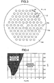
- Fig. 3 is a schematic cross section of the dispersion-compensating holey fiber 12 shown in Fig. 1 .
- the dispersion-compensating holey fiber 12 is a holey fiber having a structure similar to that of the negative-dispersion holey fiber 11.
- a core region 12a and a cladding region 12b are both made of pure silica glass, and adjacent air holes 12c are arranged to form a triangular lattice L2.
- a diameter of each of the air holes 12c is d2 and a pitch between centers of the adjacent air holes 12c is A2.
- the air holes 12c are arranged in a five-layer structure in the present embodiment.
- a wavelength dispersion is negative and a DPS (Dispersion Per Slope) value obtained by dividing the wavelength dispersion by a dispersion slope value is -200 nm to -50 nm at a wavelength of 1050 nm.
- the wavelength dispersion is positive and the DPS value is -800 nm to -50 nm at the wavelength of 1050 nm. That is, the optical transmission line 10 is configured by coupling the negative-dispersion holey fiber 11 to the dispersion-compensating holey fiber 12.
- the wavelength dispersion and the dispersion slope are concurrently compensated, the wavelength dispersion across a broad bandwidth including the wavelength of 1050 nm is reduced, and the wavelength dispersion is less dependent on the wavelength.
- the DPS value is -200 nm to -50 nm, an effective core area increases, so that optical nonlinearity can be reduced and confinement loss can be reduced. Therefore, the optical transmission line 10 is suitable for optical transmission across a broad bandwidth in the wavelength band of 1.0 ⁇ m.
- Design parameters to realize the negative-dispersion holey fiber 11 and the dispersion-compensating holey fiber 12 as described above and various characteristics obtained by the design parameters are specifically explained using results of calculation obtained by a simulation using a finite element method (FEM).
- FEM finite element method
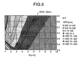
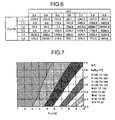
- Figs. 4 , 5 , 7 are graphs explaining relations between A and d/A with signs of wavelength dispersion, DPS value, and effective core area Aeff at the wavelength of 1050 nm in holey fibers having a similar structure to that shown in Fig. 2 .
- Fig. 6 is a table explaining results of more detailed calculations in a region where A is 1 ⁇ m to 1.5 ⁇ m shown in Fig. 5 .
- Fig. 8 is a graph explaining results of more detailed calculations in a region where A is 1 ⁇ m to 1.5 ⁇ m shown in Fig. 7 . As shown in Fig.
- FIG. 2 can realize an increased effective core area in the negative dispersion region, so that optical nonlinearity can be reduced.
- a region in which A is from 10 ⁇ m to 12 ⁇ m is not shown, however, each characteristics in this region is a characteristics that tends to be successive from the characteristics observed in the region where the A is equal to or less than 10 ⁇ m.
- This region is represented as the negative dispersion region shown in Fig. 4 and as the region with the DPS value in a range from -200 nm to -100 nm shown in Fig. 5 .
- this region is represented as the region in which the effective core area increases as the d/A decreases.
- the DPS value of -200 nm to -50 nm is attainable.
- the A increases, bending loss characteristics degrades.
- the d/ ⁇ decreases, it is getting harder to confine light into the core region, so that the number of the air hole layers required increases to keep confinement loss equal to or less than 0.1 dB/km. If the number of the air hole layers increases, for example, to equal to or more than eight layers, the total number of the air holes will be equal to or more than 200, leading to complicated manufacturing.
- the A and the d/A increase, it is getting harder to maintain a single-mode operation at a wavelength of 1000 nm.
- the A1 be 6 ⁇ m to 12 ⁇ m and the d1/A1 be 0.3 to 0.7 for the negative-dispersion holey fiber 11 according to the first embodiment. If the ⁇ 1 is 6 ⁇ m to 12 ⁇ m and the d1/ ⁇ 1 is 0.3 to 0.7, the confinement loss of equal to or less than 0.1 dB/km is attainable while keeping the number of the air hole layers equal to or less than seven layers.
- the effective core area can be made equal to or larger than 45 ⁇ m 2 . so that optical nonlinearity equivalent to or lower than that for a dispersion-shifted optical fiber (DSF) generally used as an optical transmission line and defined in ITU-T G.653 is attainable.
- DSF dispersion-shifted optical fiber
- the wavelength dispersion is -30 ps/nm/km to -15 ps/nm/km and the DPS value is -150 nm to -100 nm for the negative-dispersion holey fiber 11 at the wavelength of 1050 nm.
- Fig. 9 is a table explaining design parameters and optical characteristics at the wavelength of 1050 nm of holey fibers in calculation examples 1 to 20, for which preferable values are set to the design parameters of A, d/A, and the number of air hole layers.
- mode represents a state of a propagation mode of a holey fiber.
- SM represents that a holey fiber performs a single-mode operation and
- MM represents that a holey fiber performs a multimode operation.
- the calculation examples 1 to 20 exhibit satisfactory values in any of confinement loss, DPS value, and effective core area.
- bending loss for a diameter of 20 mm is equal to or less than 10 dB/m at wavelengths of 1050 nm and 1550 nm and realizes values usable as an optical transmission line.
- the dispersion-compensating holey fiber 12 has the DPS value of -800 nm to -50 nm at the wavelength of 1050 nm, of which absolute value is in a range larger than that of the DPS value for the negative-dispersion holey fiber 11.
- the absolute value of the DPS for the dispersion-compensating holey fiber 12 at the wavelength of 1050 nm is set to be larger than the absolute value of the DPS for the negative-dispersion holey fiber 11 at the wavelength of 1050 nm, even when there is necessity of compensating wavelength dispersion in a broader wavelength bandwidth between 1000 nm and 1300 nm later, residual dispersion within the wavelength bandwidth can be reduced. The detail will be explained later.
- the effective core area of a holey fiber is reduced in the positive dispersion region.
- the effective core area be equal to or larger than 1.0 ⁇ m 2 .
- the design parameters be such that the A2 is 0.9 ⁇ m to 1.3 ⁇ m and the d2/A2 is 0.5 to 0.9. If the A2 is 0.9 ⁇ m to 1.3 ⁇ m and the d2/A2 is 0.5 to 0.9, confinement loss can be made equal to or less than 0.1 dB/km at the wavelength of 1050 nm while the number of the air hole layers is equal to or less than seven layers.
- the effective core area is equal to or larger than 1.0 ⁇ m 2 . In this case, wavelength dispersion is 20 ps/nm/km to 150 ps/nm/km.
- Fig. 10 is a table explaining design parameters and optical characteristics at the wavelength of 1050 nm of holey fibers in the calculation examples 21 to 28, for which preferable values are set to the design parameters of A, d/A, and the number of air hole layers.
- the calculation examples 21 to 28 exhibit satisfactory values in any of confinement loss, DPS value, and effective core area.
- bending loss for a diameter of 20 mm is equal to or less than 10 dB/m at wavelengths of 1050 nm and 1550 nm and realizes values usable as an optical transmission line.
- Fig. 11 is a graph explaining dispersion characteristics of the negative-dispersion holey fiber 11 when the values of the calculation example 10 shown in Fig. 9 are set to the design parameters.
- Fig. 12 is a graph explaining residual dispersion in the optical transmission line 10 according to the first embodiment.
- the residual dispersion in the optical transmission line 10 is such a considerably small value as ⁇ 1.5 ps/nm/km at a wavelength of 1000 nm to 1100 nm.
- Transmission speed of an optical signal at a transmission distance of 100 km can be made 10 Gbps if the absolute value of the residual dispersion is equal to or less than 10 ps/nm/km, and the transmission speed at a transmission distance of 20 km can be made 40 Gbps if the absolute value of the residual dispersion is equal to or less than 5 ps/nm/km.
- Fig. 13 is a graph explaining a relation between d/A of the dispersion-compensating holey fiber 12 with a DPS value at the wavelength of 1050 nm and a maximum absolute value of residual dispersion in the optical transmission line 10 at a wavelength of 1000 nm to 1300 nm.
- the dispersion-compensating holey fiber 12 employs 1.0 ⁇ m for A and six layers for the number of the layers of the air holes 12c.
- FIG. 14 is a graph explaining a relation between d/A of the dispersion-compensating holey fibers 12 and wavelength dispersion at the wavelength of 1050 nm.
- the wavelength dispersion and the absolute value of the DPS value increases.
- the d/A is 0.78 and the DPS value is -300 nm, that is, the absolute value of the DPS value is set to be larger than that for the negative-dispersion holey fiber 11, the maximum absolute value of the residual dispersion in the optical transmission line 10 at the wavelengths of 1000 nm to 1300 nm is minimum; thereby compensating wavelength dispersion most satisfactorily.
- Fig. 15 is a graph explaining residual dispersion in the optical transmission line 10 when a DPS value for the dispersion-compensating holey fiber 12 is made to be - 300 nm.
- the curve showing residual dispersion shifts toward a side of long wavelengths compared with the case shown in Fig. 12 .
- the curve is nearly symmetrical about approximately 1150 nm that is the center wavelength of the wavelengths of 1000 nm to 1300 nm, and wavelength dispersion in the optical transmission line 10 can be most satisfactorily compensated.
- the length of the dispersion-compensating holey fiber 12 required for dispersion-compensating can be made short, which is preferable.
- Fig. 16 is a block diagram of an optical transmission system 100 according to the second embodiment.
- the optical transmission system 100 includes an optical transmitter 20 that outputs an optical signal, the optical transmission line 10 according to the first embodiment connected to the optical transmitter 20, and an optical receiver 30 connected to the optical transmission line 10.
- the optical transmitter 20 includes a light source such as a fiber laser.
- An optical signal having any one of wavelengths of 1000 nm to 1100 nm and, for example, a transmission speed of 10 GHz is output from this light source.
- the optical transmission line 10 transmits the optical signal output from the optical transmitter 20.
- the optical transmission line 10 has less residual dispersion at wavelengths of 1000 nm to 1100 nm, allowing to transmit the optical signal with less distortion.
- the optical receiver 30 includes a photodetector and receives the optical signal transmitted by the optical transmission line 10 with less distortion.
- the optical transmission line 10 is connected to the optical transmitter 20 at the side of the negative-dispersion holey fiber 11.
- the effective core area of the negative-dispersion holey fiber 11 is significantly increased compared with that of the dispersion-compensating holey fiber 12, so that the optical nonlinearity is significantly reduced. Therefore, by coupling the optical transmission line 10 such that an optical signal having high light intensity just after being output from the optical transmitter 20 is firstly input into the negative-dispersion holey fiber 11, an adverse effect on the optical signal caused by the optical nonlinearity of the optical transmission line 10 can be suppressed.
- the optical transmitter 20 and the optical receiver 30 are connected with the single optical transmission line 10; however, can be connected with an optical transmission line configured by continuously coupling a plurality of the optical transmission lines 10 via a regenerative repeater.
- a regenerative repeater for example, an optical fiber amplifier using YDF can be employed.
- a holey fiber is used for the dispersion-compensating optical fiber; however, it is not limited to the present embodiments as far as the dispersion-compensating optical fiber has a positive wavelength dispersion and a DPS value of -800 nm to -50 nm.
- a high-order-mode dispersion-compensating optical fiber as reported by Siddharth Ramachandran, et al., OFC/NFOEC 2007 Technical Digest, OWI1 is usable.
- the present invention can be preferably used to realize optical transmission across a broad bandwidth in a wavelength band of 1.0 ⁇ m.
Landscapes
- Physics & Mathematics (AREA)
- Chemical & Material Sciences (AREA)
- Dispersion Chemistry (AREA)
- General Physics & Mathematics (AREA)
- Optics & Photonics (AREA)
- Electromagnetism (AREA)
- Engineering & Computer Science (AREA)
- Computer Networks & Wireless Communication (AREA)
- Signal Processing (AREA)
- Optical Fibers, Optical Fiber Cores, And Optical Fiber Bundles (AREA)
- Optical Communication System (AREA)
Abstract
Description
- The present invention relates to an optical transmission line and an optical transmission system for transmitting an optical signal in a wavelength band of 1.0 µm.
- A holey fiber or a photonic crystal fiber is a new type of an optical fiber that includes a core region at its center and a cladding region arranged on an outer circumference of the core region. The cladding region includes a plurality of air holes around the core region to propagate light in the core region by lowering average refractive index of the cladding region using the air holes and by utilizing the principle of total reflection of light. The holey fiber controls the refractive index using the air holes, so that specific characteristics, such as an Endlessly Single Mode (ESM), which has been unachievable by conventional optical fibers, zero-dispersion wavelength, which is shifted toward a side of extremely short wavelengths, or the like, can be realized. The ESM means characteristics in which the cutoff wavelength does not exist and lights at all wavelengths are transmitted in the single mode, so that high-transmission-speed optical transmission can be achieved across a broad bandwidth.
- On the other hand, recently a technology for an Ytterbium-doped optical fiber (YDF) usable as an amplifying optical fiber in a wavelength band of 1.0 µm having a wavelength bandwidth from 1000 nm to 1100 nm or 1300 nm has been being matured. Accordingly, there are increasing demands for a fiber laser for the 1.0-µm wavelength band, an optical fiber for an SC light source, and an optical fiber applicable to an optical transmission line and the like. A holey fiber is expected to meet such a demand. For example, in
Nonpatent Document 1, results are reported of experiment on light transmissions across a broad bandwidth including a wavelength of 1064 nm using a holey fiber as an optical transmission line. - Nonpatent Document 1: K. Ieda, et al., "Visible to Infrared WDM transmission over PCF", ECOC2006-Tu3.3.4 (2006)
- In a conventional holey fiber, however, a wavelength dispersion in the 1.0-µm wavelength band is, for example, equal to or less than -20 ps/nm/km, so that an absolute value of the wavelength dispersion is large. Accordingly, when using this holey fiber as an optical transmission line to transmit an optical signal in the 1.0-µm wavelength band, there is a problem that the optical signal severely distorts and its quality degrades. Furthermore, because the conventional holey fiber has a dispersion slope, an optical signal differently distorts depending on the wavelength. Therefore, when using, for example, a wavelength-division multiplexing (WDM) signal as an optical signal, the quality of the optical signal may vary depending on the wavelength of the optical signal. Accordingly, the conventional holey fiber is not appropriate for an optical transmission across a broad bandwidth.
- The present invention has been achieved in view of the above, and it is an object of the present invention to provide an optical transmission line and an optical transmission system suitable for an optical transmission across a broad bandwidth in a wavelength band of 1.0 µm.
- To solve the above problems and to achieve the object, an optical transmission line according to the present invention includes a negative-dispersion holey fiber that includes a core region arranged at a center, and a cladding region arranged on an outer circumference of the core region, which includes air holes arranged in a triangular lattice around the core region; and a dispersion-compensating optical fiber connected to the negative dispersion holey fiber. The negative-dispersion holey fiber has a negative wavelength dispersion at a wavelength of 1050 nm and a DPS value, which is obtained by dividing the wavelength dispersion at the wavelength of 1050 nm by a dispersion slope value, of -200 nm to -50 nm. The dispersion-compensating optical fiber has a positive wavelength dispersion at the wavelength of 1050 nm and the DPS value at the wavelength of 1050 nm of -800 nm to -50 nm.
- Furthermore, the optical transmission line according to the present invention is featured in that, in the above-described invention, an absolute value of a residual dispersion at a wavelength of 1000 nm to 1100 nm is equal to or smaller than 5 ps/nm/km.
- Moreover, the optical transmission line according to the present invention is featured in that, in the above-described invention, an absolute value of a residual dispersion at a wavelength of 1000 nm to 1300 nm is equal to or smaller than 10 ps/nm/km.
- Furthermore, the optical transmission line according to the present invention is featured in that, in the above-described invention, the negative dispersion holey fiber has A1 of 6 µm to 12 µm and d1/A1 of 0.3 to 0.7, where d1 is diameter of each of the air holes in [µm] and A1 is lattice constant of the triangular lattice in [µm], a confinement loss of equal to or smaller than 0.1 dB/km, a wavelength dispersion of -30 ps/nm/km to -15 ps/nm/km, and the DPS value of -150 nm to -100 nm at the wavelength of 1050 nm.
- Moreover, the optical transmission line according to the present invention is featured in that, in the above-described invention, the negative dispersion holey fiber has an effective core area of equal to or larger than 45 µm2 at the wavelength of 1050 nm.
- Furthermore, the optical transmission line according to the present invention is featured in that, in the above-described invention, the dispersion-compensating optical fiber is a holey fiber that includes a core region arranged at a center and a cladding region that is arranged on an outer circumference of the core region, the cladding region including air holes arranged in a triangular lattice around the core region.
- Moreover, the optical transmission line according to the present invention is featured in that, in the above-described invention, the dispersion-compensating optical fiber has A2 of 0.9 µm to 1.3 µm and d2/A2 of 0.5 to 0.9, where d2 is diameter of each of the air holes in [µm] and A2 is lattice constant of the triangular lattice in [µm], a confinement loss of equal to or smaller than 0.1 dB/km, and a wavelength dispersion of 20 ps/nm/km to 150 ps/nm/km at the wavelength of 1050 nm.
- Furthermore, the optical transmission line according to the present invention is featured in that, in the above-described invention, the dispersion-compensating optical fiber has an effective core area of equal to or larger than 1.0 µm2 at the wavelength of 1050 nm.
- Moreover, an optical transmission system according to the present invention includes an optical transmitter that outputs an optical signal; an optical transmission line according to any one of
claims 1 to 8 that is connected to the optical transmitter and transmits the optical signal output from the optical transmitter; and an optical receiver that is connected to the optical transmission line and receives the optical signal transmitted by the optical transmission line. The optical transmission line is connected to the optical transmitter at the negative-dispersion holey fiber side. - According to the present invention, an optical transmission line and an optical transmission system suitable for an optical transmission across a broad bandwidth in a wavelength band of 1.0 µm are advantageously attainable.
-
- [
Fig. 1] Fig. 1 is a block diagram explaining a schematic configuration of an optical transmission line according to a first embodiment of the present invention. - [
Fig. 2] Fig. 2 is a schematic cross section of a negative-dispersion holey fiber shown inFig. 1 . - [
Fig. 3] Fig. 3 is a schematic cross section of a dispersion-compensating holey fiber shown inFig. 1 . - [
Fig. 4] Fig. 4 is a graph explaining a relation between A and d/A with signs of wavelength dispersion at a wavelength of 1050 nm in holey fibers having a similar structure to that shown inFig. 2 . - [
Fig. 5] Fig. 5 is a graph explaining a relation between A and d/A with a DPS value at the wavelength of 1050 nm in a holey fiber having a similar structure to that shown inFig. 2 . - [
Fig. 6] Fig. 6 is a table explaining results of more detailed calculations in a region where A is 1 µm to 1.5 µm shown inFig. 5 . - [
Fig. 7] Fig. 7 is a graph explaining a relation between A and d/A with an effective core area Aeff at the wavelength of 1050 nm in holey fibers having a similar structure to that shown inFig. 2 . - [
Fig. 8] Fig. 8 is a graph explaining results of more detailed calculations in a region where A is 1 µm to 1.5 µm in shownFig. 7 . - [
Fig. 9] Fig. 9 is a table explaining design parameters and optical characteristics at the wavelength of 1050 nm of holey fibers in calculation examples 1 to 20, for which preferable values are set to the design parameters of A, d/A, and the number of air hole layers. - [
Fig. 10] Fig. 10 is a table explaining design parameters and optical characteristics at the wavelength of 1050 nm of holey fibers in calculation examples 21 to 28, for which preferable values are set to the design parameters of A, d/A, and the number of air hole layers. - [
Fig. 11] Fig. 11 is a graph explaining dispersion characteristics of a negative-dispersion holey fiber when values of calculation example 10 shown inFig. 9 are set to design parameters. - [
Fig. 12] Fig. 12 is a graph explaining residual dispersion in the optical transmission line according to the first embodiment. - [
Fig. 13] Fig. 13 is a graph explaining relations of d/A of a dispersion-compensating holey fiber with a DPS value at the wavelength of 1050 nm and a maximum absolute value of residual dispersion in an optical transmission line at a wavelength of 1000 nm to 1300 nm. - [
Fig. 14] Fig. 14 is a graph explaining a relation between d/A of a dispersion-compensating holey fiber and wavelength dispersion at the wavelength of 1050 nm. - [
Fig. 15] Fig. 15 is a graph explaining residual dispersion in an optical transmission line when a DPS value for a dispersion-compensating holey fiber is made to be - 300 nm. - [
Fig. 16] Fig. 16 is a block diagram of an optical transmission system according to a second embodiment of the present invention. -
- 10 optical transmission line
- 11 negative-dispersion holey fiber
- 11a core region
- 11b cladding region
- 11c air hole
- 12 dispersion-compensating holey fiber
- 12a core region
- 12b cladding region
- 12c air hole
- 20 optical transmitter
- 30 optical receiver
- 100 optical transmission system
- L1, L2 triangular lattice
- Exemplary embodiments of an optical transmission line and an optical transmission system according to the present invention are explained in detail below with reference to the accompanying drawings. However, the present invention is not limited by the present embodiments. Unless otherwise specified herein, the terms are in accordance with the definitions or measurement methods in ITU-T (International Telecommunication Union Telecommunication Standardization Sector) G.650.1.
-
Fig. 1 is a block diagram explaining a schematic configuration of anoptical transmission line 10 according to a first embodiment of the present invention. As shown inFig. 1 , theoptical transmission line 10 includes a negative-dispersion holey fiber 11 and a dispersion-compensatingholey fiber 12 that is a dispersion-compensating optical fiber connected to the negative-dispersion holey fiber 11. -
Fig. 2 is a schematic cross section of the negative-dispersion holey fiber 11 shown inFig. 1 . As shown inFig. 2 , the negative-dispersion holey fiber 11 includes acore region 11a arranged at a center and acladding region 11b arranged on an outer circumference of thecore region 11a. Thecore region 11a and thecladding region 11b are both made of pure silica glass without doping a dopant for adjusting refractive index. - The
cladding region 11b hasair holes 11c formed around thecore region 11a. Theadjacent air holes 11c are arranged to form a triangular lattice L1. A diameter of each of theair holes 11c is d1 and a lattice constant of the triangular lattice L1, that is, a pitch between centers of theadjacent air holes 11c is A1. Furthermore, theair holes 11c are placed on sides and vertexes of different regular hexagons relative to a center point of thecore region 11a. Assuming that a combination of theair holes 11c placed on the same regular hexagon is a single layer, theair holes 11c are arranged in a five-layer structure in the present embodiment. - By contrast,
Fig. 3 is a schematic cross section of the dispersion-compensatingholey fiber 12 shown inFig. 1 . As shown inFig. 3 , the dispersion-compensatingholey fiber 12 is a holey fiber having a structure similar to that of the negative-dispersion holey fiber 11. Acore region 12a and acladding region 12b are both made of pure silica glass, andadjacent air holes 12c are arranged to form a triangular lattice L2. A diameter of each of theair holes 12c is d2 and a pitch between centers of theadjacent air holes 12c is A2. The air holes 12c are arranged in a five-layer structure in the present embodiment. - In the negative-
dispersion holey fiber 11, a wavelength dispersion is negative and a DPS (Dispersion Per Slope) value obtained by dividing the wavelength dispersion by a dispersion slope value is -200 nm to -50 nm at a wavelength of 1050 nm. By contrast, in the dispersion-compensatingholey fiber 12, the wavelength dispersion is positive and the DPS value is -800 nm to -50 nm at the wavelength of 1050 nm. That is, theoptical transmission line 10 is configured by coupling the negative-dispersion holey fiber 11 to the dispersion-compensatingholey fiber 12. Between the negative-dispersion holey fiber 11 and the dispersion-compensatingholey fiber 12, signs of the wavelength dispersions differ and the DPS values are similar levels. Therefore, the wavelength dispersion and the dispersion slope are concurrently compensated, the wavelength dispersion across a broad bandwidth including the wavelength of 1050 nm is reduced, and the wavelength dispersion is less dependent on the wavelength. Moreover, if the DPS value is -200 nm to -50 nm, an effective core area increases, so that optical nonlinearity can be reduced and confinement loss can be reduced. Therefore, theoptical transmission line 10 is suitable for optical transmission across a broad bandwidth in the wavelength band of 1.0 µm. - Design parameters to realize the negative-
dispersion holey fiber 11 and the dispersion-compensatingholey fiber 12 as described above and various characteristics obtained by the design parameters are specifically explained using results of calculation obtained by a simulation using a finite element method (FEM). -
Figs. 4 ,5 ,7 are graphs explaining relations between A and d/A with signs of wavelength dispersion, DPS value, and effective core area Aeff at the wavelength of 1050 nm in holey fibers having a similar structure to that shown inFig. 2 .Fig. 6 is a table explaining results of more detailed calculations in a region where A is 1 µm to 1.5 µm shown inFig. 5 .Fig. 8 is a graph explaining results of more detailed calculations in a region where A is 1 µm to 1.5 µm shown inFig. 7 . As shown inFig. 4 , there are a positive dispersion region in which the sign of wavelength dispersion is positive and a negative dispersion region in which the sign of wavelength dispersion is negative in a combination of the A and the d/A. By referring toFigs. 4 ,5 , and6 , there are solutions for the combinations of the A and the d/A in which the DPS values are similar levels between the positive dispersion region and the negative dispersion region. As shown inFig. 7 , the effective core area increases as the effective core area is reaching toward the lower right region in which the A increases and the d/A decreases. As shown inFig. 4 , this region is the negative dispersion region. Namely, the holey fibers having a similar structure to that shown inFig. 2 can realize an increased effective core area in the negative dispersion region, so that optical nonlinearity can be reduced. InFigs. 4 ,5 , and7 , a region in which A is from 10 µm to 12 µm is not shown, however, each characteristics in this region is a characteristics that tends to be successive from the characteristics observed in the region where the A is equal to or less than 10 µm. This region is represented as the negative dispersion region shown inFig. 4 and as the region with the DPS value in a range from -200 nm to -100 nm shown inFig. 5 . InFig. 7 , this region is represented as the region in which the effective core area increases as the d/A decreases. - As shown in
Fig. 5 , if the A1 is 5 µm to 12 µm and d1/A1 is 0.2 to 0.8 for the negative-dispersion holey fibers 11, the DPS value of -200 nm to -50 nm is attainable. On the other hand, as the A increases, bending loss characteristics degrades. Furthermore, as the d/Λ decreases, it is getting harder to confine light into the core region, so that the number of the air hole layers required increases to keep confinement loss equal to or less than 0.1 dB/km. If the number of the air hole layers increases, for example, to equal to or more than eight layers, the total number of the air holes will be equal to or more than 200, leading to complicated manufacturing. As the A and the d/A increase, it is getting harder to maintain a single-mode operation at a wavelength of 1000 nm. - Therefore, it is preferable that the A1 be 6 µm to 12 µm and the d1/A1 be 0.3 to 0.7 for the negative-
dispersion holey fiber 11 according to the first embodiment. If the Λ1 is 6 µm to 12 µm and the d1/Λ1 is 0.3 to 0.7, the confinement loss of equal to or less than 0.1 dB/km is attainable while keeping the number of the air hole layers equal to or less than seven layers. In addition, the effective core area can be made equal to or larger than 45 µm2. so that optical nonlinearity equivalent to or lower than that for a dispersion-shifted optical fiber (DSF) generally used as an optical transmission line and defined in ITU-T G.653 is attainable. In this case, the wavelength dispersion is -30 ps/nm/km to -15 ps/nm/km and the DPS value is -150 nm to -100 nm for the negative-dispersion holey fiber 11 at the wavelength of 1050 nm. - Preferable design parameters for the negative-
dispersion holey fiber 11 according to the first embodiment are explained based on specific calculation examples.Fig. 9 is a table explaining design parameters and optical characteristics at the wavelength of 1050 nm of holey fibers in calculation examples 1 to 20, for which preferable values are set to the design parameters of A, d/A, and the number of air hole layers. InFig. 9 , "mode" represents a state of a propagation mode of a holey fiber. "SM" represents that a holey fiber performs a single-mode operation and "MM" represents that a holey fiber performs a multimode operation. As shown inFig. 9 , the calculation examples 1 to 20 exhibit satisfactory values in any of confinement loss, DPS value, and effective core area. Moreover, in any of the calculation examples 1 to 20, bending loss for a diameter of 20 mm is equal to or less than 10 dB/m at wavelengths of 1050 nm and 1550 nm and realizes values usable as an optical transmission line. - Next, the dispersion-compensating
holey fiber 12 according to the first embodiment is specifically explained. As described above, the dispersion-compensatingholey fiber 12 has the DPS value of -800 nm to -50 nm at the wavelength of 1050 nm, of which absolute value is in a range larger than that of the DPS value for the negative-dispersion holey fiber 11. - In this manner, if the absolute value of the DPS for the dispersion-compensating
holey fiber 12 at the wavelength of 1050 nm is set to be larger than the absolute value of the DPS for the negative-dispersion holey fiber 11 at the wavelength of 1050 nm, even when there is necessity of compensating wavelength dispersion in a broader wavelength bandwidth between 1000 nm and 1300 nm later, residual dispersion within the wavelength bandwidth can be reduced. The detail will be explained later. - As shown in
Fig. 5 , if the A2 is 0.9 µm to 1.3 µm and d2/A2 is 0.5 to 0.9 for the dispersion-compensatingholey fiber 12, the DPS value of -800 nm to -50 nm is attainable. Furthermore, as shown inFigs 4 ,6 , the effective core area of a holey fiber is reduced in the positive dispersion region. However, in view of connectivity to another optical fiber, it is preferable that the effective core area be equal to or larger than 1.0 µm2. - In light of the above, in the dispersion-compensating
holey fiber 12 according to the first embodiment, it is preferable that the design parameters be such that the A2 is 0.9 µm to 1.3 µm and the d2/A2 is 0.5 to 0.9. If the A2 is 0.9 µm to 1.3 µm and the d2/A2 is 0.5 to 0.9, confinement loss can be made equal to or less than 0.1 dB/km at the wavelength of 1050 nm while the number of the air hole layers is equal to or less than seven layers. In addition, the effective core area is equal to or larger than 1.0 µm2. In this case, wavelength dispersion is 20 ps/nm/km to 150 ps/nm/km. - Preferable design parameters for the dispersion-compensating
holey fiber 12 according to the first embodiment are explained based on specific calculation examples.Fig. 10 is a table explaining design parameters and optical characteristics at the wavelength of 1050 nm of holey fibers in the calculation examples 21 to 28, for which preferable values are set to the design parameters of A, d/A, and the number of air hole layers. As shown inFig. 10 , the calculation examples 21 to 28 exhibit satisfactory values in any of confinement loss, DPS value, and effective core area. Moreover, in any of the calculation examples 21 to 28, bending loss for a diameter of 20 mm is equal to or less than 10 dB/m at wavelengths of 1050 nm and 1550 nm and realizes values usable as an optical transmission line. - Residual dispersion characteristics in the
optical transmission line 10 according to the first embodiment are explained. As the design parameters for the negative-dispersion holey fiber 11, the values of the calculation example 10 shown inFig. 9 are used, so that the DPS value at the wavelength of 1050 nm is -123.3 nm. As the design parameters for the dispersion-compensatingholey fiber 12, the values of the calculation example 22 shown inFig. 10 are used, so that the DPS value at the wavelength of 1050 nm is -149.3 nm that is similar level to the DPS value for the negative-dispersion holey fiber 11.Fig. 11 is a graph explaining dispersion characteristics of the negative-dispersion holey fiber 11 when the values of the calculation example 10 shown inFig. 9 are set to the design parameters. -
Fig. 12 is a graph explaining residual dispersion in theoptical transmission line 10 according to the first embodiment. As shown inFig. 12 , the residual dispersion in theoptical transmission line 10 is such a considerably small value as ±1.5 ps/nm/km at a wavelength of 1000 nm to 1100 nm. Transmission speed of an optical signal at a transmission distance of 100 km can be made 10 Gbps if the absolute value of the residual dispersion is equal to or less than 10 ps/nm/km, and the transmission speed at a transmission distance of 20 km can be made 40 Gbps if the absolute value of the residual dispersion is equal to or less than 5 ps/nm/km. - A case of dispersion-compensating the
optical transmission line 10 according to the first embodiment at a wavelength of 1000 nm to 1300 nm is explained.Fig. 13 is a graph explaining a relation between d/A of the dispersion-compensatingholey fiber 12 with a DPS value at the wavelength of 1050 nm and a maximum absolute value of residual dispersion in theoptical transmission line 10 at a wavelength of 1000 nm to 1300 nm. The dispersion-compensatingholey fiber 12 employs 1.0 µm for A and six layers for the number of the layers of theair holes 12c.Fig. 14 is a graph explaining a relation between d/A of the dispersion-compensatingholey fibers 12 and wavelength dispersion at the wavelength of 1050 nm. As shown inFigs. 13 ,14 , in the dispersion-compensatingholey fiber 12, as the d/A increases, the wavelength dispersion and the absolute value of the DPS value increases. When the d/A is 0.78 and the DPS value is -300 nm, that is, the absolute value of the DPS value is set to be larger than that for the negative-dispersion holey fiber 11, the maximum absolute value of the residual dispersion in theoptical transmission line 10 at the wavelengths of 1000 nm to 1300 nm is minimum; thereby compensating wavelength dispersion most satisfactorily. -
Fig. 15 is a graph explaining residual dispersion in theoptical transmission line 10 when a DPS value for the dispersion-compensatingholey fiber 12 is made to be - 300 nm. As shown inFig. 15 , by setting the larger absolute value of the DPS value for the dispersion-compensatingholey fiber 12, the curve showing residual dispersion shifts toward a side of long wavelengths compared with the case shown inFig. 12 . As a result, the curve is nearly symmetrical about approximately 1150 nm that is the center wavelength of the wavelengths of 1000 nm to 1300 nm, and wavelength dispersion in theoptical transmission line 10 can be most satisfactorily compensated. As the absolute value of the DPS value for the dispersion-compensatingholey fiber 12 increases, the wavelength dispersion increases. Accordingly, the length of the dispersion-compensatingholey fiber 12 required for dispersion-compensating can be made short, which is preferable. - An optical transmission system according to a second embodiment of the present invention is explained.
Fig. 16 is a block diagram of anoptical transmission system 100 according to the second embodiment. As shown inFig. 16 , theoptical transmission system 100 includes anoptical transmitter 20 that outputs an optical signal, theoptical transmission line 10 according to the first embodiment connected to theoptical transmitter 20, and anoptical receiver 30 connected to theoptical transmission line 10. - The
optical transmitter 20 includes a light source such as a fiber laser. An optical signal having any one of wavelengths of 1000 nm to 1100 nm and, for example, a transmission speed of 10 GHz is output from this light source. Theoptical transmission line 10 transmits the optical signal output from theoptical transmitter 20. As stated above, theoptical transmission line 10 has less residual dispersion at wavelengths of 1000 nm to 1100 nm, allowing to transmit the optical signal with less distortion. Moreover, theoptical receiver 30 includes a photodetector and receives the optical signal transmitted by theoptical transmission line 10 with less distortion. - Furthermore, the
optical transmission line 10 is connected to theoptical transmitter 20 at the side of the negative-dispersion holey fiber 11. The effective core area of the negative-dispersion holey fiber 11 is significantly increased compared with that of the dispersion-compensatingholey fiber 12, so that the optical nonlinearity is significantly reduced. Therefore, by coupling theoptical transmission line 10 such that an optical signal having high light intensity just after being output from theoptical transmitter 20 is firstly input into the negative-dispersion holey fiber 11, an adverse effect on the optical signal caused by the optical nonlinearity of theoptical transmission line 10 can be suppressed. - In the second embodiment, the
optical transmitter 20 and theoptical receiver 30 are connected with the singleoptical transmission line 10; however, can be connected with an optical transmission line configured by continuously coupling a plurality of theoptical transmission lines 10 via a regenerative repeater. In this case, as the regenerative repeater, for example, an optical fiber amplifier using YDF can be employed. - In the first and second embodiments, a holey fiber is used for the dispersion-compensating optical fiber; however, it is not limited to the present embodiments as far as the dispersion-compensating optical fiber has a positive wavelength dispersion and a DPS value of -800 nm to -50 nm. For example, a high-order-mode dispersion-compensating optical fiber (HOM-DCF) as reported by Siddharth Ramachandran, et al., OFC/NFOEC 2007 Technical Digest, OWI1 is usable.
- The present invention can be preferably used to realize optical transmission across a broad bandwidth in a wavelength band of 1.0 µm.
Claims (9)
- An optical transmission line comprising:a negative-dispersion holey fiber that includes
a core region arranged at a center, and
a cladding region arranged on an outer circumference of the core region, the cladding region including air holes arranged in a triangular lattice around the core region; anda dispersion-compensating optical fiber connected to the negative dispersion holey fiber, whereinthe negative-dispersion holey fiber has a negative wavelength dispersion at a wavelength of 1050 nm and a DPS value, which is obtained by dividing the wavelength dispersion at the wavelength of 1050 nm by a dispersion slope value, of -200 nm to -50 nm, andthe dispersion-compensating optical fiber has a positive wavelength dispersion at the wavelength of 1050 nm and the DPS value at the wavelength of 1050 nm of -800 nm to -50 nm. - The optical transmission line according to claim 1, wherein an absolute value of a residual dispersion at a wavelength of 1000 nm to 1100 nm is equal to or smaller than 5 ps/nm/km.
- The optical transmission line according to claim 1 or 2, wherein an absolute value of a residual dispersion at a wavelength of 1000 nm to 1300 nm is equal to or smaller than 10 ps/nm/km.
- The optical transmission line according to any one of claims 1 to 3, wherein the negative dispersion holey fiber has A1 of 6 µm to 12 µm and d1/Λ1 of 0.3 to 0.7, where d1 is diameter of each of the air holes in [µm] and Λ1 is lattice constant of the triangular lattice in [µm], a confinement loss of equal to or smaller than 0.1 dB/km, a wavelength dispersion of -30 ps/nm/km to -15 ps/nm/km, and the DPS value of -150 nm to -100 nm at the wavelength of 1050 nm.
- The optical transmission line according to any one of claims 1 to 4, wherein the negative dispersion holey fiber has an effective core area of equal to or larger than 45 µm2 at the wavelength of 1050 nm.
- The optical transmission line according to any one of claims 1 to 5, wherein the dispersion-compensating optical fiber is a holey fiber that includes a core region arranged at a center and a cladding region that is arranged on an outer circumference of the core region, the cladding region including air holes arranged in a triangular lattice around the core region.
- The optical transmission line according to claim 6, wherein the dispersion-compensating optical fiber has A2 of 0.9 µm to 1.3 µm and d2/A2 of 0.5 to 0.9, where d2 is diameter of each of the air holes in [µm] and A2 is lattice constant of the triangular lattice in [µm], a confinement loss of equal to or smaller than 0.1 dB/km, and a wavelength dispersion of 20 ps/nm/km to 150 ps/nm/km at the wavelength of 1050 nm.
- The optical transmission line according to claim 7, wherein the dispersion-compensating optical fiber has an effective core area of equal to or larger than 1.0 µm2 at the wavelength of 1050 nm.
- An optical transmission system comprising:an optical transmitter that outputs an optical signal;an optical transmission line according to any one of claims 1 to 8 that is connected to the optical transmitter and transmits the optical signal output from the optical transmitter; andan optical receiver that is connected to the optical transmission line and receives the optical signal transmitted by the optical transmission line, whereinthe optical transmission line is connected to the optical transmitter at the negative-dispersion holey fiber side.
Applications Claiming Priority (2)
| Application Number | Priority Date | Filing Date | Title |
|---|---|---|---|
| JP2007207741A JP5137492B2 (en) | 2007-08-09 | 2007-08-09 | Optical transmission line and optical transmission system |
| PCT/JP2008/063795 WO2009020049A1 (en) | 2007-08-09 | 2008-07-31 | Optical transmission path and optical transmission system |
Publications (2)
| Publication Number | Publication Date |
|---|---|
| EP2045634A1 true EP2045634A1 (en) | 2009-04-08 |
| EP2045634A4 EP2045634A4 (en) | 2013-08-14 |
Family
ID=40341283
Family Applications (1)
| Application Number | Title | Priority Date | Filing Date |
|---|---|---|---|
| EP08792010.4A Withdrawn EP2045634A4 (en) | 2007-08-09 | 2008-07-31 | Optical transmission path and optical transmission system |
Country Status (4)
| Country | Link |
|---|---|
| US (1) | US7693380B2 (en) |
| EP (1) | EP2045634A4 (en) |
| JP (1) | JP5137492B2 (en) |
| WO (1) | WO2009020049A1 (en) |
Cited By (1)
| Publication number | Priority date | Publication date | Assignee | Title |
|---|---|---|---|---|
| EP2765443A4 (en) * | 2011-10-04 | 2015-06-10 | Furukawa Electric Co Ltd | Optical fiber and optical transmission system |
Families Citing this family (8)
| Publication number | Priority date | Publication date | Assignee | Title |
|---|---|---|---|---|
| US7903919B2 (en) * | 2007-09-10 | 2011-03-08 | Furukawa Electric Co., Ltd. | Holey fiber |
| US20110091176A1 (en) * | 2009-08-03 | 2011-04-21 | Furukawa Electric Co., Ltd. | Holey fibers |
| JP5520622B2 (en) * | 2010-01-29 | 2014-06-11 | 古河電気工業株式会社 | Photonic band gap fiber manufacturing method and photonic band gap fiber |
| EP2549306A1 (en) | 2010-03-16 | 2013-01-23 | Furukawa Electric Co., Ltd. | Holey fiber |
| JP5619516B2 (en) | 2010-08-04 | 2014-11-05 | 古河電気工業株式会社 | Optical fiber |
| US9075243B2 (en) * | 2011-03-01 | 2015-07-07 | Ofs Fitel, Llc | Method and system for ultrashort pulse fiber delivery using higher order mode fiber |
| US8849083B1 (en) * | 2011-04-28 | 2014-09-30 | Nufern | All glass leakage channel fibers and devices using them |
| US8811784B2 (en) | 2011-10-04 | 2014-08-19 | Furukawa Electric Co., Ltd. | Optical fiber and optical transmission system |
Citations (1)
| Publication number | Priority date | Publication date | Assignee | Title |
|---|---|---|---|---|
| US20060159410A1 (en) * | 2004-11-01 | 2006-07-20 | Tatsuhiko Saito | Optical fiber |
Family Cites Families (9)
| Publication number | Priority date | Publication date | Assignee | Title |
|---|---|---|---|---|
| US5191631A (en) * | 1991-12-19 | 1993-03-02 | At&T Bell Laboratories | Hybrid optical fiber and method of increasing the effective area of optical transmission using same |
| US6718105B2 (en) | 2000-02-23 | 2004-04-06 | Sumitomo Electric Industries, Ltd. | Optical fiber |
| JP2001235649A (en) * | 2000-02-23 | 2001-08-31 | Sumitomo Electric Ind Ltd | Optical fiber |
| US6526209B1 (en) * | 2000-04-17 | 2003-02-25 | Sumitomo Electric Industries, Ltd. | Optical fiber having improved optics and structure |
| US6792188B2 (en) * | 2000-07-21 | 2004-09-14 | Crystal Fibre A/S | Dispersion manipulating fiber |
| CN1582519A (en) * | 2001-12-21 | 2005-02-16 | 皮雷利&C.有限公司 | Raman amplification usin microstructured fiber |
| US6901197B2 (en) * | 2003-01-13 | 2005-05-31 | Sumitomo Electric Industries, Ltd. | Microstructured optical fiber |
| US7280730B2 (en) * | 2004-01-16 | 2007-10-09 | Imra America, Inc. | Large core holey fibers |
| EP2051115A1 (en) * | 2007-02-02 | 2009-04-22 | The Furukawa Electric Co., Ltd. | Optical transmission system and dispersion-compensated optical fiber |
-
2007
- 2007-08-09 JP JP2007207741A patent/JP5137492B2/en not_active Expired - Fee Related
-
2008
- 2008-07-31 WO PCT/JP2008/063795 patent/WO2009020049A1/en active Application Filing
- 2008-07-31 EP EP08792010.4A patent/EP2045634A4/en not_active Withdrawn
-
2009
- 2009-01-28 US US12/361,281 patent/US7693380B2/en not_active Expired - Fee Related
Patent Citations (1)
| Publication number | Priority date | Publication date | Assignee | Title |
|---|---|---|---|---|
| US20060159410A1 (en) * | 2004-11-01 | 2006-07-20 | Tatsuhiko Saito | Optical fiber |
Non-Patent Citations (6)
| Title |
|---|
| KENJI KUROKAWA ET AL: "Penalty-Free Dispersion-Managed Soliton Transmission Over a 100-km Low-Loss PCF", JOURNAL OF LIGHTWAVE TECHNOLOGY, IEEE SERVICE CENTER, NEW YORK, NY, US, vol. 24, no. 1, 1 January 2006 (2006-01-01), pages 32-37, XP001545405, ISSN: 0733-8724, DOI: 10.1109/JLT.2005.861146 * |
| KOJI IEDA ET AL: "Visible to infrared high-speed WDM transmission over PCF", IEICE ELECTRONICS EXPRESS, DENSHI JOUHOU TSUUSHIN GAKKAI, JP, vol. 4, no. 12, 25 June 2007 (2007-06-25), pages 375-379, XP008104375, ISSN: 1349-2543, DOI: 10.1587/ELEX.4.375 * |
| KYOZO TSUJIKAWA ET AL: "Application of a Prechirp Technique to 10-Gb/s Transmission at 1064 nm Through 24 km of Photonic Crystal Fiber", IEEE PHOTONICS TECHNOLOGY LETTERS, IEEE SERVICE CENTER, PISCATAWAY, NJ, US, vol. 18, no. 19, 1 October 2006 (2006-10-01), pages 2026-2028, XP008104377, ISSN: 1041-1135, DOI: 10.1109/LPT.2006.883324 * |
| See also references of WO2009020049A1 * |
| TSUJIKAWA K ET AL: "Penalty-free 10 Gb/s transmission in 1.0 /spl mu/m band over 24 km low PCF", 31ST EUROPEAN CONFERENCE ON OPTICAL COMMUNICATION - 25-29 SEPT. 2005 - GLASGOW, UK, LONDON : INSTITUTION OF ELECTRICAL ENGINEERS, GB, 25 September 2005 (2005-09-25), pages 283-284vol.2, XP032173465, ISBN: 978-0-86341-543-2 * |
| ZHOU J ET AL: "Progress on low loss photonic crystal fibers", OPTICAL FIBER TECHNOLOGY, ACADEMIC PRESS, LONDON, US, vol. 11, no. 2, 1 April 2005 (2005-04-01), pages 101-110, XP004807486, ISSN: 1068-5200, DOI: 10.1016/J.YOFTE.2004.12.002 * |
Cited By (1)
| Publication number | Priority date | Publication date | Assignee | Title |
|---|---|---|---|---|
| EP2765443A4 (en) * | 2011-10-04 | 2015-06-10 | Furukawa Electric Co Ltd | Optical fiber and optical transmission system |
Also Published As
| Publication number | Publication date |
|---|---|
| JP5137492B2 (en) | 2013-02-06 |
| US7693380B2 (en) | 2010-04-06 |
| WO2009020049A1 (en) | 2009-02-12 |
| US20090162020A1 (en) | 2009-06-25 |
| EP2045634A4 (en) | 2013-08-14 |
| JP2009042523A (en) | 2009-02-26 |
Similar Documents
| Publication | Publication Date | Title |
|---|---|---|
| EP2045634A1 (en) | Optical transmission path and optical transmission system | |
| US7881579B2 (en) | Optical transmission system and dispersion-compensating optical fiber | |
| US10324253B2 (en) | Few mode optical fibers for mode division multiplexing having intermediate trenches | |
| CN105683791B (en) | Less fundamental mode optical fibre link used in space division multiplexing | |
| EP1116970A1 (en) | Optical transmission line | |
| EP1146358A1 (en) | Optical fiber and optical transmission system including the same | |
| EP1927872A1 (en) | Optical fiber | |
| JP2002365464A (en) | Positive dispersion optical fiber having large effective area | |
| JP5379689B2 (en) | Holey fiber | |
| JP6265960B2 (en) | Optical fiber and optical transmission system | |
| US20080219667A1 (en) | Optical communication system and dispersion-compensating optical fiber | |
| EP2293126A1 (en) | Holey fiber | |
| US20110026890A1 (en) | Holey fibers | |
| EP1148360A2 (en) | Photonic crystal fibers for dispersion control in optical communication systems | |
| US20110091176A1 (en) | Holey fibers | |
| JP5079664B2 (en) | Optical wavelength division multiplexing communication system, exciter and mode filter | |
| EP1507154B1 (en) | Dispersion shift optical fiber | |
| EP3414604B1 (en) | Few mode optical fibers for mode division multiplexing | |
| US7805040B2 (en) | Optical communication system | |
| EP1259840B1 (en) | Optical fiber for wdm transmission | |
| EP1653640A1 (en) | Fiberoptics, fiberoptic transmission line and optical transmission system | |
| JP2005003794A (en) | Optical fiber and optical transmission line using the same | |
| JP2009086558A (en) | Dispersion compensating optical fiber, optical transmission system, and method for designing dispersion compensating optical fiber |
Legal Events
| Date | Code | Title | Description |
|---|---|---|---|
| PUAI | Public reference made under article 153(3) epc to a published international application that has entered the european phase |
Free format text: ORIGINAL CODE: 0009012 |
|
| 17P | Request for examination filed |
Effective date: 20090202 |
|
| AK | Designated contracting states |
Kind code of ref document: A1 Designated state(s): AT BE BG CH CY CZ DE DK EE ES FI FR GB GR HR HU IE IS IT LI LT LU LV MC MT NL NO PL PT RO SE SI SK TR |
|
| AX | Request for extension of the european patent |
Extension state: AL BA MK RS |
|
| DAX | Request for extension of the european patent (deleted) | ||
| RBV | Designated contracting states (corrected) |
Designated state(s): DK GB |
|
| REG | Reference to a national code |
Ref country code: DE Ref legal event code: 8566 |
|
| A4 | Supplementary search report drawn up and despatched |
Effective date: 20130715 |
|
| RIC1 | Information provided on ipc code assigned before grant |
Ipc: G02B 6/032 20060101ALI20130709BHEP Ipc: G02B 6/00 20060101AFI20130709BHEP |
|
| STAA | Information on the status of an ep patent application or granted ep patent |
Free format text: STATUS: EXAMINATION IS IN PROGRESS |
|
| 17Q | First examination report despatched |
Effective date: 20151006 |
|
| STAA | Information on the status of an ep patent application or granted ep patent |
Free format text: STATUS: THE APPLICATION IS DEEMED TO BE WITHDRAWN |
|
| 18D | Application deemed to be withdrawn |
Effective date: 20160217 |