JP5028706B2 - Optical fiber and optical transmission system - Google Patents
Optical fiber and optical transmission system Download PDFInfo
- Publication number
- JP5028706B2 JP5028706B2 JP2000132652A JP2000132652A JP5028706B2 JP 5028706 B2 JP5028706 B2 JP 5028706B2 JP 2000132652 A JP2000132652 A JP 2000132652A JP 2000132652 A JP2000132652 A JP 2000132652A JP 5028706 B2 JP5028706 B2 JP 5028706B2
- Authority
- JP
- Japan
- Prior art keywords
- wavelength
- signal light
- refractive index
- optical fiber
- less
- Prior art date
- Legal status (The legal status is an assumption and is not a legal conclusion. Google has not performed a legal analysis and makes no representation as to the accuracy of the status listed.)
- Expired - Fee Related
Links
Images


Description
【0001】
【発明の属する技術分野】
本発明は、多波長の信号光を多重化して光伝送を行う波長多重(WDM: Wavelength Division Multiplexing)伝送システム、および、この光伝送システムにおいて光伝送路として用いられる光ファイバに関するものである。
【0002】
【従来の技術】
光ファイバ網を用いたWDM伝送システムは、大容量の情報を伝送することが可能であり、多波長の信号光を送信する送信器、これらの信号光を伝送する光ファイバ、これらの信号光を受信する受信器、および、信号光を光増幅する光増幅器、等を含んで構成される。このようなWDM伝送システムにおいて、伝送容量を拡大するために、信号光の波長帯域の幅を広げる試みがなされている。
【0003】
また、非線型光学現象(特に四光波混合)に因る信号光の波形劣化を抑制するためには、信号光波長帯域において光ファイバの波長分散の絶対値が小さすぎないことが重要である。一方、累積波長分散に因る信号光の波形劣化を抑制するためには、信号光波長帯域において光ファイバの波長分散の絶対値が大きすぎないことも重要である。
【0004】
ところで、光ファイバ増幅器が利得を有する波長帯域が1.53μm〜1.61μm程度であるのに対して、従来の分散シフト光ファイバの零分散波長は1.56μm〜1.60μmの範囲にある。したがって、このような光ファイバ増幅器と分散シフト光ファイバとを含む光伝送システムでは、光ファイバ増幅器が利得を有する波長帯域のうちであっても、分散シフト光ファイバの零分散波長の付近の波長で非線型光学現象が発生し易いので、この波長の信号光を用いて長距離伝送を行うことができない。
【0005】
このような問題点を解消することを意図した光ファイバが国際公開WO99/30194号公報に開示されている。この光ファイバは、零分散波長が1.61μm以上1.67μm以下であり、波長1.55μmにおける波長分散スロープが0.15ps/nm2/km以下である。そして、この光ファイバは、光ファイバ増幅器が利得を有する波長帯域1.53μm〜1.61μmにおいて、波長分散の絶対値が適切な値となって、非線型光学現象に因る信号光の波形劣化および累積波長分散に因る信号光の波形劣化の双方を抑制することができるというものである。また、この公報に実施例として示された光ファイバの波長分散スロープは0.07ps/nm2/km〜0.15ps/nm2/kmである。
【0006】
【発明が解決しようとする課題】
WDM伝送システムにおいて更なる伝送容量の拡大を図るには、信号光の波長帯域の幅を更に拡大することが望まれる。しかしながら、上記公報に開示された光ファイバは、波長1.55μm帯(Cバンド)および波長1.58μm帯(Lバンド)を含む波長帯域1.53μm〜1.61μmでの使用を意図したものであって、1.31μm帯および1.45μm帯(Sバンド)での使用については考慮されていない。すなわち、上記公報に示された光ファイバは、波長1.31μmにおいて、波長分散が−20ps/nm/kmより小さくなり、波長分散の絶対値が大きいことから、累積波長分散に因る信号光の波形劣化が生じ易いので、波長1.31μm帯の信号光を用いて長距離伝送を行うことができない。
【0007】
本発明は、上記問題点を解消する為になされたものであり、波長1.31μm帯、波長1.45μm帯、波長1.55μm帯および波長1.58μm帯を含む広い信号光波長帯域の多波長の信号光を用いて大容量の長距離伝送が可能な光ファイバ、および、この光ファイバを含む光伝送システムを提供することを目的とする。
【0008】
【課題を解決するための手段】
本発明に係る光ファイバは、波長1.30μm〜波長1.60μmの2波長以上の光を伝送できる光伝送路用の光ファイバであり、光軸中心を含み第1の屈折率を有する中心コア領域と、この中心コア領域を取り囲み第1の屈折率より小さい第2の屈折率を有する第2コア領域と、この第2コア領域を取り囲み第2の屈折率より大きい第3の屈折率を有する第3コア領域と、この第3コア領域を取り囲み第3の屈折率より小さい第4の屈折率を有するクラッド領域とを備え、クラッド領域が、第3の屈折率より小さい屈折率を有する内層クラッド領域と、この内層クラッドの屈折率より大きい屈折率を有する外層クラッド領域とを含み、中心コア領域の外径2aが5.0μm以上5.7μm以下であり、第2コア領域の外径2bが14.3μm以上15.1μm以下であり、第3コア領域の外径2cが21.3μm以上22.6μm以下であり、内層クラッド領域の外径2dが42.6μm以上45.2μm以下であり、クラッド領域の最外層の屈折率を基準として、中心コア領域の比屈折率差が0.5%以上0.59%以下であり、第2コア領域の比屈折率差が−0.2%以上−0.15%以下であり、第3コア領域の比屈折率差が0.25%以上0.30%以下であり、内層クラッド領域の比屈折率差が−0.2%以上−0.15%以下であり、波長帯域1.30μm〜1.60μmの全範囲において波長分散が−20ps/nm/km以上−3ps/nm/km以下であり、波長1.55μmにおける実効断面積が40μm2以上であり、波長1.38μmにおけるOH基に因るロス増が0.1dB/km以下であり、ケーブルカットオフ波長が1.33μm以下であることを特徴とする。
より好適には、上記の波長帯域1.30μm〜1.60μmの全範囲において波長分散が−12ps/nm/km以上−4ps/nm/km以下であることを特徴とする。また、より好適には、上記の波長帯域より広い波長帯域1.25μm〜1.65μmの全範囲において波長分散が−20ps/nm/km以上−3ps/nm/km以下であることを特徴とする。更に好適には、より広い波長帯域1.25μm〜1.65μmの全範囲において波長分散が−16ps/nm/km以上−4ps/nm/km以下であることを特徴とする。
【0009】
この光ファイバによれば、波長1.31μm帯、波長1.45μm帯、波長1.55μm帯および波長1.58μm帯を含む広い信号光波長帯域(1.30μm〜1.60μm、より好適には1.25μm〜1.65μm)において、波長分散が上記数値範囲内の値であるので、非線型光学現象に因る信号光の波形劣化および累積波長分散に因る信号光の波形劣化の双方が抑制される。したがって、この光ファイバを光伝送路として用いれば、この広い信号光波長帯域の多波長の信号光を用いて大容量の長距離伝送が可能である。なお、本発明に係る光ファイバの波長分散の絶対値が20ps/nm/km以下であるというのは、符号が異なるものの、ITUのG.654に規定されているシングルモード光ファイバの波長1.55μmにおける波長分散と同程度以下であり、信号光を伝送する上で問題はない。
【0010】
また、本発明に係る光ファイバは、波長1.55μmにおける実効断面積が52.1μm 2 以下であるのが好適である。
【0013】
本発明に係る光伝送システムは、(1) 波長帯域1.30μm〜1.60μm(より好適には、波長帯域1.25μm〜1.65μm)内の各波長の信号光を送出する複数の送信器と、(2) これら複数の送信器それぞれから送出された信号光を伝送する上記の本発明に係る光ファイバと、(3) この光ファイバを伝送してきて到達した信号光を受信する受信器とを備えることを特徴とする。この光伝送システムは、上記の本発明に係る光ファイバを光伝送路として用いているので、波長1.31μm帯、波長1.45μm帯、波長1.55μm帯および波長1.58μm帯を含む広い信号光波長帯域(1.30μm〜1.60μm、より好適には1.25μm〜1.65μm)において、非線型光学現象に因る信号光の波形劣化および累積波長分散に因る信号光の波形劣化の双方が抑制され、この広い信号光波長帯域の多波長の信号光を用いて大容量の長距離伝送が可能である。
【0014】
【発明の実施の形態】
以下、添付図面を参照して本発明の実施の形態を詳細に説明する。なお、図面の説明において同一の要素には同一の符号を付し、重複する説明を省略する。
【0015】
図1は、本実施形態に係る光ファイバの波長分散特性を説明する図である。本実施形態に係る光ファイバは、波長帯域1.30μm〜1.60μm(以下では「信号光波長帯域A」という。)の全範囲において、波長分散が−20ps/nm/km以上−3ps/nm/km以下である。この信号光波長帯域Aは、波長1.31μm帯、波長1.45μm帯、波長1.55μm帯および波長1.58μm帯を含んでいる。また、この信号光波長帯域Aの全範囲において波長分散が−20ps/nm/km以上−3ps/nm/km以下であるので、非線型光学現象に因る信号光の波形劣化および累積波長分散に因る信号光の波形劣化の双方が抑制される。したがって、この光ファイバを光伝送路として用いれば、この広い信号光波長帯域Aの多波長の信号光を用いて大容量の長距離伝送が可能である。
【0016】
より好適には、本実施形態に係る光ファイバは、信号光波長帯域Aの全範囲において、波長分散が−12ps/nm/km以上−4ps/nm/km以下である。この場合には、波長分散が−12ps/nm/km以上であることにより、累積波長分散に因る信号光の波形劣化が更に抑制され、波長分散が−4ps/nm/km以下であることにより、非線型光学現象に因る信号光の波形劣化が更に抑制される。したがって、信号光波長帯域Aの多波長の信号光を用いて更に大容量の長距離伝送が可能である。
【0017】
また、より好適には、本実施形態に係る光ファイバは、上記の信号光波長帯域Aより広い波長帯域1.25μm〜1.65μm(以下では「信号光波長帯域B」という。)の全範囲において、波長分散が−20ps/nm/km以上−3ps/nm/km以下である。この場合には、信号光波長帯域Aより広い信号光波長帯域Bの多波長の信号光を用いて更に大容量の長距離伝送が可能である。
【0018】
更に好適には、本実施形態に係る光ファイバは、信号光波長帯域Bの全範囲において、波長分散が−16ps/nm/km以上−4ps/nm/km以下である。この場合には、波長分散が−16ps/nm/km以上であることにより、累積波長分散に因る信号光の波形劣化が更に抑制され、波長分散が−4ps/nm/km以下であることにより、非線型光学現象に因る信号光の波形劣化が更に抑制される。したがって、信号光波長帯域Bの多波長の信号光を用いて更に大容量の長距離伝送が可能である。
【0019】
また、本実施形態に係る光ファイバは、波長1.55μmにおける実効断面積が40μm2以上であるのが好適である。この場合には、実効断面積が充分に大きいことから、非線型光学現象に因る信号光の波形劣化が更に抑制され、長距離伝送を行う上で好適である。
【0020】
また、本実施形態に係る光ファイバは、波長1.38μmにおけるOH基に因るロス増が0.1dB/km以下であるのが好適である。この場合には、波長1.38μm付近の波長をも信号光波長として用いることができるので、更に大容量の伝送が可能である。
【0021】
次に、本実施形態に係る光ファイバを実現するのに好適な屈折率プロファイルについて説明する。図2は、本実施形態に係る光ファイバの屈折率プロファイルの好適例を説明する図である。この図に示された屈折率プロファイルは、光軸中心から順に、中心コア領域(屈折率n1、外径2a)、第2コア領域(屈折率n2、外径2b)、第3コア領域(屈折率n3、外径2c)およびクラッド領域(屈折率n4)を有している。各屈折率の大小関係は n1>n2 であり、n2<n3 であり、n3>n4 である。より好適には、クラッド領域の最外層の屈折率を基準として中心コア領域の比屈折率差Δ1が0.4%以上0.7%以下である。このような屈折率プロファイルを有する光ファイバは、石英ガラスをベースとして、例えば、中心コア領域および第3コア領域それぞれにGeO2を添加することにより、及び/又は、第2コア領域およびクラッド領域それぞれにF元素を添加することにより、実現することができる。
【0022】
図3は、本実施形態に係る光ファイバの屈折率プロファイルの好適例を説明する図である。この図に示された屈折率プロファイルは、光軸中心から順に、中心コア領域(屈折率n1、外径2a)、第2コア領域(屈折率n2、外径2b)、第3コア領域(屈折率n3、外径2c)、内層クラッド領域(屈折率n4、外径2d)および外層クラッド領域(屈折率n5)を有している。各屈折率の大小関係は n1>n2 であり、n2<n3 であり、n3>n4 であり、n4<n5 である。より好適には、外層クラッド領域の最外層の屈折率を基準として中心コア領域の比屈折率差Δ1が0.4%以上0.7%以下である。このような屈折率プロファイルを有する光ファイバは、石英ガラスをベースとして、例えば、中心コア領域および第3コア領域それぞれにGeO2を添加することにより、及び/又は、第2コア領域および内層クラッド領域それぞれにF元素を添加することにより、実現することができる。
【0023】
次に、本実施形態に係る光ファイバの具体的な4つの実施例について説明する。何れの実施例の光ファイバも図3に示した屈折率プロファイルを有する。図4は、4つの実施例の光ファイバそれぞれの諸元および諸特性を纏めた図表である。図5は、4つの実施例の光ファイバそれぞれの波長分散特性を示すグラフである。
【0024】
第1実施例の光ファイバの諸元は以下のとおりである。中心コア領域の外径2aは5.7μmであり、第2コア領域の外径2bは14.7μmであり、第3コア領域の外径2cは22.6μmであり、内層クラッド領域の外径2dは45.2μmである。また、中心コア領域の屈折率差Δ1は0.50%であり、第2コア領域の屈折率差Δ2は−0.20%であり、第3コア領域の屈折率差Δ3は0.25%であり、内層クラッド領域の屈折率差Δ4は−0.20%である。
【0025】
そして、この第1実施例の光ファイバの諸特性は以下のとおりである。波長分散特性は、波長1.25μmで−11.98ps/nm/kmであり、波長1.31μmで−9.22ps/nm/kmであり、波長1.55μmで−8.07ps/nm/kmであり、波長1.65μmで−3.81ps/nm/kmである。波長1.55μmにおいて、波長分散スロープは0.016ps/nm2/kmであり、実効断面積は52.1μm2であり、モードフィールド径は7.95μmであり、曲げ径32mmΦでの曲げ損失は2.4dB/ターンである。零分散波長は1.694μmであり、ケーブルカットオフ波長は1.29μmである。また、波長1.38μmにおけるOH基に因るロス増Δα1.38は0.01dB/kmである。
【0026】
第2実施例の光ファイバの諸元は以下のとおりである。中心コア領域の外径2aは5.5μmであり、第2コア領域の外径2bは14.5μmであり、第3コア領域の外径2cは21.3μmであり、内層クラッド領域の外径2dは42.6μmである。また、中心コア領域の屈折率差Δ1は0.55%であり、第2コア領域の屈折率差Δ2は−0.20%であり、第3コア領域の屈折率差Δ3は0.30%であり、内層クラッド領域の屈折率差Δ4は−0.20%である。
【0027】
そして、この第2実施例の光ファイバの諸特性は以下のとおりである。波長分散特性は、波長1.25μmで−11.82ps/nm/kmであり、波長1.31μmで−8.81ps/nm/kmであり、波長1.55μmで−6.28ps/nm/kmであり、波長1.65μmで−3.32ps/nm/kmである。波長1.55μmにおいて、波長分散スロープは0.011ps/nm2/kmであり、実効断面積は46.6μm2であり、モードフィールド径は7.44μmであり、曲げ径32mmΦでの曲げ損失は0.2dB/ターンである。零分散波長は1.700μmであり、ケーブルカットオフ波長は1.31μmである。また、波長1.38μmにおけるOH基に因るロス増Δα1.38は0.06dB/kmである。
【0028】
第3実施例の光ファイバの諸元は以下のとおりである。中心コア領域の外径2aは5.2μmであり、第2コア領域の外径2bは15.1μmであり、第3コア領域の外径2cは21.6μmであり、内層クラッド領域の外径2dは43.2μmである。また、中心コア領域の屈折率差Δ1は0.57%であり、第2コア領域の屈折率差Δ2は−0.20%であり、第3コア領域の屈折率差Δ3は0.29%であり、内層クラッド領域の屈折率差Δ4は−0.20%である。
【0029】
そして、この第3実施例の光ファイバの諸特性は以下のとおりである。波長分散特性は、波長1.25μmで−12.60ps/nm/kmであり、波長1.31μmで−9.42ps/nm/kmであり、波長1.55μmで−7.99ps/nm/kmであり、波長1.65μmで−7.10ps/nm/kmである。波長1.55μmにおいて、波長分散スロープは−0.008ps/nm2/kmであり、実効断面積は42.1μm2であり、モードフィールド径は7.15μmであり、曲げ径32mmΦでの曲げ損失は1.5dB/ターンである。零分散波長は1.757μmであり、ケーブルカットオフ波長は1.22μmである。また、波長1.38μmにおけるOH基に因るロス増Δα1.38は0.03dB/kmである。
【0030】
第4実施例の光ファイバの諸元は以下のとおりである。中心コア領域の外径2aは5.0μmであり、第2コア領域の外径2bは14.3μmであり、第3コア領域の外径2cは21.6μmであり、内層クラッド領域の外径2dは43.2μmである。また、中心コア領域の屈折率差Δ1は0.59%であり、第2コア領域の屈折率差Δ2は−0.15%であり、第3コア領域の屈折率差Δ3は0.27%であり、内層クラッド領域の屈折率差Δ4は−0.15%である。
【0031】
そして、この第4実施例の光ファイバの諸特性は以下のとおりである。波長分散特性は、波長1.25μmで−16.40ps/nm/kmであり、波長1.31μmで−14.30ps/nm/kmであり、波長1.55μmで−14.70ps/nm/kmであり、波長1.65μmで−8.60ps/nm/kmである。波長1.55μmにおいて、波長分散スロープは0.027ps/nm2/kmであり、実効断面積は49.3μm2であり、モードフィールド径は7.75μmであり、曲げ径32mmΦでの曲げ損失は0.8dB/ターンである。零分散波長は1.724μmであり、ケーブルカットオフ波長は1.33μmである。また、波長1.38μmにおけるOH基に因るロス増Δα1.38は0.03dB/kmである。
【0032】
以上説明した第1〜第4実施例それぞれの光ファイバは、何れも、信号光波長帯域A(波長帯域1.30μm〜1.60μm)の全範囲において、波長分散が−20ps/nm/km以上−3ps/nm/km以下であり、また、信号光波長帯域B(波長帯域1.25μm〜1.65μm)の全範囲においても、波長分散が−20ps/nm/km以上−3ps/nm/km以下である。また、第1〜第4実施例それぞれの光ファイバは、何れも、波長1.55μmにおける実効断面積が40μm2以上であり、波長1.38μmにおけるOH基に因るロス増が0.1dB/km以下である。第1〜第3実施例それぞれの光ファイバは、信号光波長帯域Aの全範囲において、波長分散が−12ps/nm/km以上−4ps/nm/km以下である。また、第3実施例の光ファイバは、信号光波長帯域Bの全範囲において、波長分散が−16ps/nm/km以上−4ps/nm/km以下である。
【0033】
次に、本実施形態に係る光ファイバを光伝送路として用いた光伝送システムの第1の実施形態について説明する。図6は、第1の実施形態に係る光伝送システム1の概略構成図である。この光伝送システム1は、送信局110と受信局120との間に光ファイバ130が光伝送路として敷設されたものである。
【0034】
送信局110は、N台(N≧2)の送信器1111〜111Nおよび合波器112を含む。送信器111n(ただし、nは1以上N以下の任意の整数。以下同様。)は、信号光波長帯域A(または信号光波長帯域B)内の波長λnの信号光を出力する。波長λ1〜λNのうち、何れかの波長は波長1.31μm帯にあり、他の何れかの波長は波長1.45μm帯にあり、更に他の何れかの波長は波長1.55μm帯にあり、その他の波長は波長1.58μm帯にある。合波器112は、送信器1111〜111Nから送出された波長λ1〜λNの信号光を入力して合波し、この合波した多波長の信号光を光ファイバ130へ送出する。
【0035】
光ファイバ130は、送信局110の合波器112により合波されて送出された波長λ1〜λNの信号光を受信局120まで伝送する。この光ファイバ130は、信号光波長帯域Aの全範囲において波長分散が−20ps/nm/km以上−3ps/nm/km以下である。また、この光ファイバ130は、より好適には、信号光波長帯域Aの全範囲において波長分散が−12ps/nm/km以上−4ps/nm/km以下であり、或いは、信号光波長帯域Bの全範囲において波長分散が−20ps/nm/km以上−3ps/nm/km以下であり、更に好適には、信号光波長帯域Bの全範囲において波長分散が−16ps/nm/km以上−4ps/nm/km以下である。また、この光ファイバ130は、より好適には、波長1.55μmにおける実効断面積が40μm2以上であり、波長1.38μmにおけるOH基に因るロス増が0.1dB/km以下である。
【0036】
受信局120は、N台の受信器1211〜121Nおよび分波器122を含む。分波器122は、光ファイバ130を伝送してきて到達した波長λ1〜λNの信号光を入力して分波し、この分波した各波長の信号光を出力する。受信器121nは、分波器122から出力された波長λnの信号光を受信する。
【0037】
この光伝送システム1では、送信局110において送信器1111〜111Nから出力され合波器112により合波された波長λ1〜λNの信号光は、光ファイバ130を伝送されて受信局120に到達する。受信局120において、波長λ1〜λNの信号光は、分波器122により分波され、受信器1211〜121Nにより受信される。この光伝送システム1は、送信局110と受信局120との間の光伝送路として、上述した本実施形態に係る光ファイバ130を用いていることから、波長1.31μm帯、波長1.45μm帯、波長1.55μm帯および波長1.58μm帯を含む信号光波長帯域A(または信号光波長帯域B)の全範囲において、非線型光学現象に因る信号光の波形劣化および累積波長分散に因る信号光の波形劣化の双方が抑制される。したがって、この光伝送システム1は、この広い信号光波長帯域A(または信号光波長帯域B)の多波長の信号光λ1〜λNを用いて大容量の長距離伝送が可能である。
【0038】
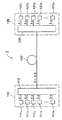
次に、本実施形態に係る光ファイバを光伝送路として用いた光伝送システムの第2の実施形態について説明する。図7は、第2の実施形態に係る光伝送システム2の概略構成図である。この光伝送システム2は、送信局210と中継局240との間に光ファイバ231が光伝送路として敷設され、また、中継局240と受信局220との間に光ファイバ232が光伝送路として敷設されたものである。
【0039】
送信局210は、N台の送信器2111〜211N、合波器2121,2122、光増幅器2131,2132、および、合波器214を含む。送信器211nは、信号光波長帯域A(または信号光波長帯域B)内の波長λnの信号光を出力する。波長λ1〜λNのうち、何れかの波長は波長1.31μm帯にあり、他の何れかの波長は波長1.45μm帯にあり、更に他の何れかの波長は波長1.55μm帯にあり、その他の波長は波長1.58μm帯にある。合波器2121は、送信器2111〜211Mから送出された第1の波長帯域に含まれる波長λ1〜λMの信号光を入力して合波して、光増幅器2131は、この合波した波長λ1〜λMの信号光を一括光増幅して出力する(ただし、1<M<N)。合波器2122は、送信器211M+1〜211Nから送出された第2の波長帯域に含まれる波長λM+1〜λNの信号光を入力して合波して、光増幅器2132は、この合波した波長λM+1〜λNの信号光を一括光増幅して出力する。合波器214は、光増幅器2131により光増幅されて出力された波長λ1〜λMの信号光、および、光増幅器2132により光増幅されて出力された波長λM+1〜λNの信号光を入力して合波し、この合波した多波長の信号光を光ファイバ231へ送出する。
【0040】
光ファイバ231は、送信局210の合波器214により合波されて送出された波長λ1〜λNの信号光を中継局240まで伝送する。この光ファイバ231は、信号光波長帯域Aの全範囲において波長分散が−20ps/nm/km以上−3ps/nm/km以下である。また、この光ファイバ231は、より好適には、信号光波長帯域Aの全範囲において波長分散が−12ps/nm/km以上−4ps/nm/km以下であり、或いは、信号光波長帯域Bの全範囲において波長分散が−20ps/nm/km以上−3ps/nm/km以下であり、更に好適には、信号光波長帯域Bの全範囲において波長分散が−16ps/nm/km以上−4ps/nm/km以下である。また、この光ファイバ231は、より好適には、波長1.55μmにおける実効断面積が40μm2以上であり、波長1.38μmにおけるOH基に因るロス増が0.1dB/km以下である。
【0041】
中継局240は、分波器241、光増幅器2421,2422および合波器243を含む。分波器241は、光ファイバ231を伝送してきて到達した波長λ1〜λNの信号光を入力して、波長λ1〜λMを含む第1の波長帯域と、波長λM+1〜λNを含む第2の波長帯域とに分波する。光増幅器2421は、分波器241から出力された第1の波長帯域に含まれる波長λ1〜λMの信号光を一括光増幅し、光増幅器2422は、分波器241から出力された第2の波長帯域に含まれる波長λM+1〜λNの信号光を一括光増幅する。そして、合波器243は、光増幅器2421により光増幅されて出力された波長λ1〜λMの信号光、および、光増幅器2422により光増幅されて出力された波長λM+1〜λNの信号光を入力して合波し、この合波した多波長の信号光を光ファイバ232へ送出する。
【0042】
光ファイバ232は、中継局240の合波器243により合波されて送出された波長λ1〜λNの信号光を受信局220まで伝送する。この光ファイバ232は、信号光波長帯域Aの全範囲において波長分散が−20ps/nm/km以上−3ps/nm/km以下である。また、この光ファイバ232は、より好適には、信号光波長帯域Aの全範囲において波長分散が−12ps/nm/km以上−4ps/nm/km以下であり、或いは、信号光波長帯域Bの全範囲において波長分散が−20ps/nm/km以上−3ps/nm/km以下であり、更に好適には、信号光波長帯域Bの全範囲において波長分散が−16ps/nm/km以上−4ps/nm/km以下である。また、この光ファイバ232は、より好適には、波長1.55μmにおける実効断面積が40μm2以上であり、波長1.38μmにおけるOH基に因るロス増が0.1dB/km以下である。
【0043】
受信局220は、N台の受信器2211〜221N、分波器2221,2222、光増幅器2231,2232、および、分波器224を含む。分波器224は、光ファイバ232を伝送してきて到達した波長λ1〜λNの信号光を入力して、波長λ1〜λMを含む第1の波長帯域と、波長λM+1〜λNを含む第2の波長帯域とに分波する。光増幅器2231は、分波器224から出力された第1の波長帯域に含まれる波長λ1〜λMの信号光を一括光増幅し、分波器2221は、この光増幅された波長λ1〜λMの信号光を波長毎に分波して出力する。光増幅器2232は、分波器224から出力された第2の波長帯域に含まれる波長λM+1〜λNの信号光を一括光増幅し、分波器2222は、この光増幅された波長λM+1〜λNの信号光を波長毎に分波して出力する。受信器221nは、分波器2221または2222から出力された波長λnの信号光を受信する。
【0044】
この光伝送システム2では、送信局210において、送信器2111〜211Mから出力された第1の波長帯域の波長λ1〜λMの信号光は、合波器2121により合波され、光増幅器2131により一括光増幅される。また、送信器211M+1〜211Nから出力された第2波長帯域の波長λM+1〜λNの信号光は、合波器2122により合波され、光増幅器2132により一括光増幅される。そして、光増幅器2131により光増幅されて出力された波長λ1〜λMの信号光、および、光増幅器2132により光増幅されて出力された波長λM+1〜λNの信号光は、合波器214により更に合波されて、光ファイバ231に送出される。送信局210から送出された波長λ1〜λNの信号光は、光ファイバ231を伝送されて中継局240に到達する。
【0045】
中継局240においては、光ファイバ231を伝送してきて到達した波長λ1〜λNの信号光は、分波器241により第1の波長帯域と第2の波長帯域とに分波される。第1の波長帯域に含まれる波長λ1〜λMの信号光は、光増幅器2421により一括光増幅され、第2の波長帯域に含まれる波長λM+1〜λNの信号光は、光増幅器2422により一括光増幅されて、これらは、合波器243により合波されて、光ファイバ232に送出される。中継局240から送出された波長λ1〜λNの信号光は、光ファイバ232を伝送されて受信局220に到達する。
【0046】
受信局220においては、光ファイバ232を伝送してきて到達した波長λ1〜λNの信号光は、分波器224により第1の波長帯域と第2の波長帯域とに分波される。第1の波長帯域に含まれる波長λ1〜λMの信号光は、光増幅器2231により一括光増幅され、分波器2221により波長毎に分波される。第2の波長帯域に含まれる波長λM+1〜λNの信号光は、光増幅器2232により一括光増幅され、分波器2222により波長毎に分波される。そして、波長λ1〜λNの信号光は、受信器2211〜221Nにより受信される。
【0047】
この光伝送システム2は、送信局210と中継局240との間の光伝送路、および、中継局240と受信局220との間の光伝送路として、上述した本実施形態に係る光ファイバ231,232を用いていることから、波長1.31μm帯、波長1.45μm帯、波長1.55μm帯および波長1.58μm帯を含む信号光波長帯域A(または信号光波長帯域B)の全範囲において、非線型光学現象に因る信号光の波形劣化および累積波長分散に因る信号光の波形劣化の双方が抑制される。したがって、この光伝送システム2は、この広い信号光波長帯域A(または信号光波長帯域B)の多波長の信号光λ1〜λNを用いて大容量の長距離伝送が可能である。
【0048】
また、この光伝送システム2では、第1の波長帯域に含まれる波長λ1〜λMの信号光を光増幅器2131,2421および2231により一括光増幅し、また、第2の波長帯域に含まれる波長λM+1〜λNの信号光を光増幅器2132,2422および2232により一括光増幅するので、この点でも長距離伝送が可能である。例えば、第1の波長帯域は波長1.55μm帯および波長1.58μm帯を含み、この第1の波長帯域内の信号光を一括光増幅する光増幅器として、Er元素が光導波領域に添加された光ファイバを光増幅媒体として用いたEr元素添加光ファイバ増幅器(EDFA: Erbium-Doped Fiber Amplifier)が好適に用いられる。一方、第2の波長帯域は波長1.31μm帯および波長1.45μm帯を含み、この第2の波長帯域内の信号光を一括光増幅する光増幅器として、半導体光増幅器やラマン増幅器が好適に用いられる。
【0049】
なお、図7に示した構成では、信号光を2つの波長帯域に分けて各々光増幅器により光増幅することとしたが、全体を1つの光増幅器により光増幅してもよいし、また、3以上の波長帯域に分けて各々光増幅器により光増幅するのも好適である。例えば、波長1.31μm帯、波長1.45μm帯、波長1.55μm帯および波長1.58μm帯の4つの波長帯域に分けてもよい。そして、波長1.31μm帯の信号光の光増幅には、Pr元素が光導波領域に添加された光ファイバを光増幅媒体として用いたPr元素添加光ファイバ増幅器(PDFA: Praseodymium-Doped Fiber Amplifier)が好適に用いられる。波長1.45μm帯の信号光の光増幅には、Tm元素が光導波領域に添加された光ファイバを光増幅媒体として用いたTm元素添加光ファイバ増幅器(TDFA: Thulium-Doped Fiber Amplifier)が好適に用いられる。波長1.55μm帯の信号光の光増幅にはEDFAが好適に用いられる。波長1.58μm帯の信号光の光増幅にもEDFAが好適に用いられる。また、何れの波長帯域の信号光の光増幅にも、半導体光増幅器やラマン増幅器が好適に用いられる。
【0050】
【発明の効果】
以上、詳細に説明したとおり、本発明に係る光ファイバは、波長帯域1.30μm〜1.60μmの全範囲において、波長分散が−20ps/nm/km以上−3ps/nm/km以下(より好適には、−12ps/nm/km以上−4ps/nm/km以下)である。また、より好適には、上記の波長帯域より広い波長帯域1.25μm〜1.65μmの全範囲において、波長分散が−20ps/nm/km以上−3ps/nm/km以下(より好適には、−16ps/nm/km以上−4ps/nm/km以下)である。この光ファイバによれば、波長1.31μm帯、波長1.45μm帯、波長1.55μm帯および波長1.58μm帯を含む広い信号光波長帯域において、波長分散が上記数値範囲内の値であるので、非線型光学現象に因る信号光の波形劣化および累積波長分散に因る信号光の波形劣化の双方が抑制される。したがって、この光ファイバを光伝送路として用いれば、この広い信号光波長帯域の多波長の信号光を用いて大容量の長距離伝送が可能である。
【0051】
本発明に係る光ファイバは、波長1.55μmにおける実効断面積が40μm2以上である場合には、非線型光学現象に因る信号光の波形劣化が更に抑制され、長距離伝送を行う上で好適である。また、本発明に係る光ファイバは、波長1.38μmにおけるOH基に因るロス増が0.1dB/km以下である場合には、波長1.38μm付近の波長をも信号光波長として用いることができるので、更に大容量の伝送が可能である。
【0052】
本発明に係る光伝送システムは、上記の本発明に係る光ファイバを光伝送路として用いているので、波長1.31μm帯、波長1.45μm帯、波長1.55μm帯および波長1.58μm帯を含む広い信号光波長帯域(1.30μm〜1.60μm、より好適には1.25μm〜1.65μm)において、非線型光学現象に因る信号光の波形劣化および累積波長分散に因る信号光の波形劣化の双方が抑制され、この広い信号光波長帯域の多波長の信号光を用いて大容量の長距離伝送が可能である。
【図面の簡単な説明】
【図1】本実施形態に係る光ファイバの波長分散特性を説明する図である。
【図2】本実施形態に係る光ファイバの屈折率プロファイルの好適例を説明する図である。
【図3】本実施形態に係る光ファイバの屈折率プロファイルの他の好適例を説明する図である。
【図4】4つの実施例の光ファイバそれぞれの諸元および諸特性を纏めた図表である。
【図5】4つの実施例の光ファイバそれぞれの波長分散特性を示すグラフである。
【図6】第1の実施形態に係る光伝送システムの概略構成図である。
【図7】第2の実施形態に係る光伝送システムの概略構成図である。
【符号の説明】
1,2…光伝送システム、110…送信局、1111〜111N…送信器、112…合波器、120…受信局、1211〜121N…受信器、122…分波器、130…光ファイバ、210…送信局、2111〜211N…送信器、2121,2122…合波器、2131,2132…光増幅器、214…合波器、220…受信局、2211〜221N…受信器、2221,2222…分波器、2231,2232…光増幅器、224…分波器、231,232…光ファイバ、240…中継局、241…分波器、2421,2422…光増幅器、243…合波器。[0001]
BACKGROUND OF THE INVENTION
The present invention relates to a wavelength division multiplexing (WDM) transmission system that performs optical transmission by multiplexing signal light of multiple wavelengths, and an optical fiber that is used as an optical transmission line in the optical transmission system.
[0002]
[Prior art]
A WDM transmission system using an optical fiber network is capable of transmitting a large amount of information, a transmitter that transmits multi-wavelength signal light, an optical fiber that transmits these signal lights, and these signal lights. The receiver includes a receiver, an optical amplifier that optically amplifies signal light, and the like. In such a WDM transmission system, an attempt has been made to expand the width of the wavelength band of signal light in order to increase the transmission capacity.
[0003]
Further, in order to suppress the waveform deterioration of the signal light due to the nonlinear optical phenomenon (particularly, four-wave mixing), it is important that the absolute value of the chromatic dispersion of the optical fiber is not too small in the signal light wavelength band. On the other hand, in order to suppress the waveform deterioration of the signal light due to the accumulated chromatic dispersion, it is also important that the absolute value of the chromatic dispersion of the optical fiber is not too large in the signal light wavelength band.
[0004]
By the way, the wavelength band in which the optical fiber amplifier has a gain is about 1.53 μm to 1.61 μm, whereas the zero dispersion wavelength of the conventional dispersion shifted optical fiber is in the range of 1.56 μm to 1.60 μm. Therefore, in such an optical transmission system including an optical fiber amplifier and a dispersion-shifted optical fiber, even in a wavelength band in which the optical fiber amplifier has a gain, at a wavelength near the zero-dispersion wavelength of the dispersion-shifted optical fiber. Since non-linear optical phenomena are likely to occur, long-distance transmission cannot be performed using signal light of this wavelength.
[0005]
An optical fiber intended to solve such problems is disclosed in International Publication No. WO99 / 30194. This optical fiber has a zero dispersion wavelength of 1.61 μm or more and 1.67 μm or less, and a chromatic dispersion slope at a wavelength of 1.55 μm is 0.15 ps / nm.2/ Km or less. In this optical fiber, the absolute value of chromatic dispersion becomes an appropriate value in the wavelength band 1.53 μm to 1.61 μm in which the optical fiber amplifier has gain, and the waveform degradation of the signal light due to the nonlinear optical phenomenon In addition, it is possible to suppress both the waveform deterioration of the signal light due to the accumulated chromatic dispersion. Further, the chromatic dispersion slope of the optical fiber shown as an example in this publication is 0.07 ps / nm.2/Km-0.15ps/nm2/ Km.
[0006]
[Problems to be solved by the invention]
In order to further increase the transmission capacity in the WDM transmission system, it is desired to further increase the width of the wavelength band of the signal light. However, the optical fiber disclosed in the above publication is intended for use in the wavelength band 1.53 μm to 1.61 μm including the wavelength 1.55 μm band (C band) and the wavelength 1.58 μm band (L band). Thus, use in the 1.31 μm band and the 1.45 μm band (S band) is not considered. That is, the optical fiber disclosed in the above publication has a wavelength dispersion of less than −20 ps / nm / km at a wavelength of 1.31 μm and a large absolute value of the wavelength dispersion. Since waveform deterioration tends to occur, long-distance transmission cannot be performed using signal light having a wavelength of 1.31 μm band.
[0007]
The present invention has been made to solve the above problems, and has a wide range of signal light wavelength bands including a wavelength 1.31 μm band, a wavelength 1.45 μm band, a wavelength 1.55 μm band, and a wavelength 1.58 μm band. It is an object of the present invention to provide an optical fiber capable of long-distance transmission with a large capacity using signal light having a wavelength, and an optical transmission system including the optical fiber.
[0008]
[Means for Solving the Problems]
An optical fiber according to the present invention is an optical fiber for an optical transmission line capable of transmitting light having a wavelength of 1.30 [mu] m to a wavelength of 1.60 [mu] m, and has a first refractive index including the center of the optical axis. A second core region surrounding the central core region and having a second refractive index less than the first refractive index and having a third refractive index surrounding the second core region and greater than the second refractive index A third core region, and a cladding region surrounding the third core region and having a fourth refractive index smaller than the third refractive index,The cladding region includes an inner cladding region having a refractive index smaller than a third refractive index, and an outer cladding region having a refractive index greater than the refractive index of the inner cladding,The outer diameter 2a of the central core region is 5.0 μm or more and 5.7 μm or less,The
More preferably, the chromatic dispersion is -12 ps / nm / km or more and -4 ps / nm / km or less over the entire range of the wavelength band from 1.30 μm to 1.60 μm. More preferably, the chromatic dispersion is -20 ps / nm / km or more and -3 ps / nm / km or less in the entire wavelength band 1.25 μm to 1.65 μm wider than the above wavelength band. . More preferably, the chromatic dispersion is -16 ps / nm / km or more and -4 ps / nm / km or less in the entire range of a wider wavelength band of 1.25 μm to 1.65 μm.
[0009]
According to this optical fiber, a wide signal light wavelength band (1.30 μm to 1.60 μm, more preferably including a wavelength 1.31 μm band, a wavelength 1.45 μm band, a wavelength 1.55 μm band, and a wavelength 1.58 μm band) 1.25 μm to 1.65 μm), the chromatic dispersion is a value within the above numerical range. Therefore, both the waveform degradation of the signal light due to the nonlinear optical phenomenon and the waveform degradation of the signal light due to the accumulated chromatic dispersion are both present. It is suppressed. Therefore, if this optical fiber is used as an optical transmission line, large-capacity long-distance transmission is possible using multi-wavelength signal light in this wide signal light wavelength band. The absolute value of the chromatic dispersion of the optical fiber according to the present invention is 20 ps / nm / km or less, although the sign is different, the wavelength of the single-mode optical fiber defined in ITU G.654 is 1. It is less than or equal to the chromatic dispersion at 55 μm, and there is no problem in transmitting signal light.
[0010]
The optical fiber according to the present invention has an effective area of 52.1 μm at a wavelength of 1.55 μm. 2 The following is preferred.
[0013]
The optical transmission system according to the present invention is (1) a plurality of transmissions for transmitting signal light of each wavelength within a wavelength band of 1.30 μm to 1.60 μm (more preferably, a wavelength band of 1.25 μm to 1.65 μm). And (2) the optical fiber according to the present invention that transmits the signal light transmitted from each of the plurality of transmitters, and (3) a receiver that receives the signal light transmitted through the optical fiber. It is characterized by providing. Since this optical transmission system uses the above-described optical fiber according to the present invention as an optical transmission line, the optical transmission system has a wide band including a wavelength band of 1.31 μm, a wavelength of 1.45 μm, a wavelength of 1.55 μm, and a wavelength of 1.58 μm. In the signal light wavelength band (1.30 μm to 1.60 μm, more preferably 1.25 μm to 1.65 μm), the waveform of the signal light due to the waveform degradation due to the nonlinear optical phenomenon and the accumulated wavelength dispersion Both degradations are suppressed, and large-capacity long-distance transmission is possible using multi-wavelength signal light in this wide signal light wavelength band.
[0014]
DETAILED DESCRIPTION OF THE INVENTION
Hereinafter, embodiments of the present invention will be described in detail with reference to the accompanying drawings. In the description of the drawings, the same elements are denoted by the same reference numerals, and redundant description is omitted.
[0015]
FIG. 1 is a diagram for explaining chromatic dispersion characteristics of an optical fiber according to this embodiment. The optical fiber according to this embodiment has a chromatic dispersion of −20 ps / nm / km or more to −3 ps / nm over the entire wavelength band of 1.30 μm to 1.60 μm (hereinafter referred to as “signal light wavelength band A”). / Km or less. This signal light wavelength band A includes a wavelength band of 1.31 μm, a wavelength of 1.45 μm, a wavelength of 1.55 μm, and a wavelength of 1.58 μm. Further, since the chromatic dispersion is -20 ps / nm / km or more and -3 ps / nm / km or less in the entire range of the signal light wavelength band A, the waveform deterioration of the signal light and the accumulated chromatic dispersion due to the nonlinear optical phenomenon are caused. Therefore, both of the waveform deterioration of the signal light are suppressed. Therefore, if this optical fiber is used as an optical transmission line, large-capacity long-distance transmission is possible using the multi-wavelength signal light in the wide signal light wavelength band A.
[0016]
More preferably, the optical fiber according to the present embodiment has a chromatic dispersion of −12 ps / nm / km or more and −4 ps / nm / km or less in the entire range of the signal light wavelength band A. In this case, when the chromatic dispersion is −12 ps / nm / km or more, the waveform degradation of the signal light due to the accumulated chromatic dispersion is further suppressed, and the chromatic dispersion is −4 ps / nm / km or less. The waveform deterioration of the signal light due to the nonlinear optical phenomenon is further suppressed. Therefore, a large-capacity long-distance transmission is possible by using multi-wavelength signal light in the signal light wavelength band A.
[0017]
More preferably, the optical fiber according to the present embodiment has a wavelength range of 1.25 μm to 1.65 μm (hereinafter referred to as “signal light wavelength band B”) wider than the signal light wavelength band A described above. , The chromatic dispersion is -20 ps / nm / km or more and -3 ps / nm / km or less. In this case, long-distance transmission with a larger capacity is possible by using multi-wavelength signal light in the signal light wavelength band B wider than the signal light wavelength band A.
[0018]
More preferably, the optical fiber according to the present embodiment has a chromatic dispersion of −16 ps / nm / km or more and −4 ps / nm / km or less in the entire range of the signal light wavelength band B. In this case, when the chromatic dispersion is −16 ps / nm / km or more, the waveform deterioration of the signal light due to the accumulated chromatic dispersion is further suppressed, and the chromatic dispersion is −4 ps / nm / km or less. The waveform deterioration of the signal light due to the nonlinear optical phenomenon is further suppressed. Therefore, a large-capacity long-distance transmission is possible using signal light of multiple wavelengths in the signal light wavelength band B.
[0019]
The optical fiber according to this embodiment has an effective area of 40 μm at a wavelength of 1.55 μm.2The above is preferable. In this case, since the effective cross-sectional area is sufficiently large, the waveform deterioration of the signal light due to the nonlinear optical phenomenon is further suppressed, which is suitable for long-distance transmission.
[0020]
In the optical fiber according to this embodiment, it is preferable that the loss increase due to the OH group at a wavelength of 1.38 μm is 0.1 dB / km or less. In this case, since a wavelength in the vicinity of a wavelength of 1.38 μm can be used as the signal light wavelength, transmission with a larger capacity is possible.
[0021]
Next, a refractive index profile suitable for realizing the optical fiber according to the present embodiment will be described. FIG. 2 is a view for explaining a preferred example of the refractive index profile of the optical fiber according to the present embodiment. The refractive index profile shown in this figure shows the central core region (refractive index n) in order from the center of the optical axis.1, Outer diameter 2a), second core region (refractive index n2,
[0022]
FIG. 3 is a view for explaining a preferred example of the refractive index profile of the optical fiber according to the present embodiment. The refractive index profile shown in this figure shows the central core region (refractive index n) in order from the center of the optical axis.1, Outer diameter 2a), second core region (refractive index n2,
[0023]
Next, four specific examples of the optical fiber according to the present embodiment will be described. The optical fiber of any embodiment has the refractive index profile shown in FIG. FIG. 4 is a table summarizing the specifications and characteristics of the optical fibers of the four examples. FIG. 5 is a graph showing the chromatic dispersion characteristics of the optical fibers of the four examples.
[0024]
The specifications of the optical fiber of the first embodiment are as follows. The outer diameter 2a of the central core region is 5.7 μm, the
[0025]
The characteristics of the optical fiber according to the first embodiment are as follows. The chromatic dispersion characteristics are -11.98 ps / nm / km at a wavelength of 1.25 μm, −9.22 ps / nm / km at a wavelength of 1.31 μm, and −8.07 ps / nm / km at a wavelength of 1.55 μm. And −3.81 ps / nm / km at a wavelength of 1.65 μm. At a wavelength of 1.55 μm, the chromatic dispersion slope is 0.016 ps / nm.2/ Km, effective area is 52.1 μm2The mode field diameter is 7.95 μm, and the bending loss at a bending diameter of 32 mmΦ is 2.4 dB / turn. The zero dispersion wavelength is 1.694 μm, and the cable cutoff wavelength is 1.29 μm. In addition, loss increase Δα due to OH group at a wavelength of 1.38 μm1.38Is 0.01 dB / km.
[0026]
The specifications of the optical fiber of the second embodiment are as follows. The outer diameter 2a of the central core region is 5.5 μm, the
[0027]
The characteristics of the optical fiber according to the second embodiment are as follows. The wavelength dispersion characteristics are −11.82 ps / nm / km at a wavelength of 1.25 μm, −8.81 ps / nm / km at a wavelength of 1.31 μm, and −6.28 ps / nm / km at a wavelength of 1.55 μm. It is −3.32 ps / nm / km at a wavelength of 1.65 μm. At a wavelength of 1.55 μm, the chromatic dispersion slope is 0.011 ps / nm.2/ Km, and the effective area is 46.6 μm.2The mode field diameter is 7.44 μm, and the bending loss at a bending diameter of 32 mmΦ is 0.2 dB / turn. The zero dispersion wavelength is 1.700 μm, and the cable cutoff wavelength is 1.31 μm. In addition, loss increase Δα due to OH group at a wavelength of 1.38 μm1.38Is 0.06 dB / km.
[0028]
The specifications of the optical fiber of the third embodiment are as follows. The outer diameter 2a of the central core region is 5.2 μm, the
[0029]
The characteristics of the optical fiber according to the third embodiment are as follows. The wavelength dispersion characteristics are -12.60 ps / nm / km at a wavelength of 1.25 μm, −9.42 ps / nm / km at a wavelength of 1.31 μm, and −7.99 ps / nm / km at a wavelength of 1.55 μm. It is −7.10 ps / nm / km at a wavelength of 1.65 μm. At a wavelength of 1.55 μm, the chromatic dispersion slope is -0.008 ps / nm.2/ Km, effective area is 42.1 μm2The mode field diameter is 7.15 μm, and the bending loss at a bending diameter of 32 mmΦ is 1.5 dB / turn. The zero dispersion wavelength is 1.757 μm and the cable cutoff wavelength is 1.22 μm. In addition, loss increase Δα due to OH group at a wavelength of 1.38 μm1.38Is 0.03 dB / km.
[0030]
The specifications of the optical fiber of the fourth embodiment are as follows. The outer diameter 2a of the central core region is 5.0 μm, the
[0031]
The characteristics of the optical fiber according to the fourth embodiment are as follows. The wavelength dispersion characteristics are -16.40 ps / nm / km at a wavelength of 1.25 μm, -14.30 ps / nm / km at a wavelength of 1.31 μm, and -14.70 ps / nm / km at a wavelength of 1.55 μm. And −8.60 ps / nm / km at a wavelength of 1.65 μm. At a wavelength of 1.55 μm, the chromatic dispersion slope is 0.027 ps / nm.2/ Km, and the effective area is 49.3 μm.2The mode field diameter is 7.75 μm, and the bending loss at a bending diameter of 32 mmΦ is 0.8 dB / turn. The zero dispersion wavelength is 1.724 μm, and the cable cutoff wavelength is 1.33 μm. In addition, loss increase Δα due to OH group at a wavelength of 1.38 μm1.38Is 0.03 dB / km.
[0032]
Each of the optical fibers of the first to fourth embodiments described above has a chromatic dispersion of −20 ps / nm / km or more in the entire range of the signal light wavelength band A (wavelength band 1.30 μm to 1.60 μm). -3 ps / nm / km or less, and chromatic dispersion is -20 ps / nm / km or more to -3 ps / nm / km in the entire range of the signal light wavelength band B (wavelength band 1.25 μm to 1.65 μm). It is as follows. Each of the optical fibers of the first to fourth embodiments has an effective area of 40 μm at a wavelength of 1.55 μm.2The increase in loss due to the OH group at a wavelength of 1.38 μm is 0.1 dB / km or less. The optical fibers of the first to third embodiments each have a chromatic dispersion of −12 ps / nm / km or more and −4 ps / nm / km or less over the entire range of the signal light wavelength band A. Further, the optical fiber of the third embodiment has a chromatic dispersion of −16 ps / nm / km or more and −4 ps / nm / km or less in the entire range of the signal light wavelength band B.
[0033]
Next, a first embodiment of an optical transmission system using the optical fiber according to the present embodiment as an optical transmission line will be described. FIG. 6 is a schematic configuration diagram of the
[0034]
The transmitting
[0035]
The
[0036]
The receiving
[0037]
In this
[0038]
Next, a second embodiment of the optical transmission system using the optical fiber according to the present embodiment as an optical transmission line will be described. FIG. 7 is a schematic configuration diagram of an
[0039]
The transmitting
[0040]
The
[0041]
The
[0042]
The
[0043]
The receiving
[0044]
In the
[0045]
In the
[0046]
At the receiving
[0047]
The
[0048]
In the
[0049]
In the configuration shown in FIG. 7, the signal light is divided into two wavelength bands and each optically amplified by an optical amplifier. However, the whole may be optically amplified by one optical amplifier, and 3 It is also preferable to optically amplify each of the above wavelength bands using an optical amplifier. For example, it may be divided into four wavelength bands, a wavelength 1.31 μm band, a wavelength 1.45 μm band, a wavelength 1.55 μm band, and a wavelength 1.58 μm band. For optical amplification of signal light having a wavelength of 1.31 μm band, a Pr element-doped optical fiber amplifier (PDFA: Praseodymium-Doped Fiber Amplifier) using an optical fiber in which Pr element is added to the optical waveguide region as an optical amplification medium. Are preferably used. For optical amplification of signal light in the wavelength band of 1.45 μm, a Tm element-doped fiber amplifier (TDFA: Thulium-Doped Fiber Amplifier) using an optical fiber in which a Tm element is added to the optical waveguide region as an optical amplification medium is suitable. Used for. An EDFA is preferably used for optical amplification of signal light having a wavelength of 1.55 μm. An EDFA is also preferably used for optical amplification of signal light having a wavelength of 1.58 μm. A semiconductor optical amplifier or a Raman amplifier is preferably used for optical amplification of signal light in any wavelength band.
[0050]
【The invention's effect】
As described above in detail, the optical fiber according to the present invention has a chromatic dispersion of −20 ps / nm / km or more and −3 ps / nm / km or less (more preferable) in the entire wavelength band of 1.30 μm to 1.60 μm. Is -12 ps / nm / km or more and -4 ps / nm / km or less). More preferably, the chromatic dispersion is -20 ps / nm / km or more and -3 ps / nm / km or less (more preferably, in the entire range of the wavelength band 1.25 μm to 1.65 μm wider than the above wavelength band). -16 ps / nm / km or more and -4 ps / nm / km or less). According to this optical fiber, the chromatic dispersion is a value within the above numerical range in a wide signal light wavelength band including a wavelength 1.31 μm band, a wavelength 1.45 μm band, a wavelength 1.55 μm band, and a wavelength 1.58 μm band. Therefore, both the waveform degradation of the signal light due to the nonlinear optical phenomenon and the waveform degradation of the signal light due to the accumulated chromatic dispersion are suppressed. Therefore, if this optical fiber is used as an optical transmission line, large-capacity long-distance transmission is possible using multi-wavelength signal light in this wide signal light wavelength band.
[0051]
The optical fiber according to the present invention has an effective area of 40 μm at a wavelength of 1.55 μm.2In the case described above, the waveform deterioration of the signal light due to the nonlinear optical phenomenon is further suppressed, which is suitable for long-distance transmission. Further, in the optical fiber according to the present invention, when the loss increase due to the OH group at a wavelength of 1.38 μm is 0.1 dB / km or less, the wavelength near 1.38 μm is also used as the signal light wavelength. Therefore, transmission with a larger capacity is possible.
[0052]
Since the optical transmission system according to the present invention uses the optical fiber according to the present invention as an optical transmission line, the wavelength 1.31 μm band, the wavelength 1.45 μm band, the wavelength 1.55 μm band, and the wavelength 1.58 μm band In a wide signal light wavelength band including 1.30 μm to 1.60 μm, more preferably 1.25 μm to 1.65 μm, a signal due to waveform degradation of signal light due to nonlinear optical phenomenon and cumulative chromatic dispersion Both deterioration of the waveform of the light is suppressed, and large-capacity long-distance transmission is possible using the multi-wavelength signal light in this wide signal light wavelength band.
[Brief description of the drawings]
FIG. 1 is a diagram for explaining chromatic dispersion characteristics of an optical fiber according to an embodiment.
FIG. 2 is a diagram illustrating a preferred example of a refractive index profile of an optical fiber according to the present embodiment.
FIG. 3 is a diagram illustrating another preferred example of the refractive index profile of the optical fiber according to the present embodiment.
FIG. 4 is a table summarizing specifications and characteristics of optical fibers of four examples.
FIG. 5 is a graph showing chromatic dispersion characteristics of optical fibers of four examples.
FIG. 6 is a schematic configuration diagram of an optical transmission system according to the first embodiment.
FIG. 7 is a schematic configuration diagram of an optical transmission system according to a second embodiment.
[Explanation of symbols]
1, 2 ... Optical transmission system, 110 ... Transmitting station, 1111~ 111N... Transmitter, 112 ... Multiplexer, 120 ... Receiving station, 1211~ 121N... Receiver, 122 ... Demultiplexer, 130 ... Optical fiber, 210 ... Transmitting station, 2111~ 211N... Transmitter, 2121, 2122... multiplexer, 2131, 2132... optical amplifier, 214 ... multiplexer, 220 ... receiving station, 2211~ 221N... Receiver, 2221, 2222... Branch, 2231, 2232... Optical amplifier, 224 ... Demultiplexer, 231, 232 ... Optical fiber, 240 ... Relay station, 241 ... Demultiplexer, 24212422... optical amplifier, 243 ... multiplexer.
Claims (7)
光軸中心を含み第1の屈折率を有する中心コア領域と、この中心コア領域を取り囲み前記第1の屈折率より小さい第2の屈折率を有する第2コア領域と、この第2コア領域を取り囲み前記第2の屈折率より大きい第3の屈折率を有する第3コア領域と、この第3コア領域を取り囲み前記第3の屈折率より小さい第4の屈折率を有するクラッド領域とを備え、
前記クラッド領域が、前記第3の屈折率より小さい屈折率を有する内層クラッド領域と、この内層クラッドの屈折率より大きい屈折率を有する外層クラッド領域とを含み、
前記中心コア領域の外径2aが5.0μm以上5.7μm以下であり、前記第2コア領域の外径2bが14.3μm以上15.1μm以下であり、前記第3コア領域の外径2cが21.3μm以上22.6μm以下であり、前記内層クラッド領域の外径2dが42.6μm以上45.2μm以下であり、
前記クラッド領域の最外層の屈折率を基準として、前記中心コア領域の比屈折率差が0.5%以上0.59%以下であり、前記第2コア領域の比屈折率差が−0.2%以上−0.15%以下であり、前記第3コア領域の比屈折率差が0.25%以上0.30%以下であり、前記内層クラッド領域の比屈折率差が−0.2%以上−0.15%以下であり、
波長帯域1.30μm〜1.60μmの全範囲において波長分散が−20ps/nm/km以上−3ps/nm/km以下であり、
波長1.55μmにおける実効断面積が40μm2以上であり、
波長1.38μmにおけるOH基に因るロス増が0.1dB/km以下であり、
ケーブルカットオフ波長が1.33μm以下である
ことを特徴とする光伝送路用の光ファイバ。An optical fiber for an optical transmission line capable of transmitting light having a wavelength of 1.30 μm to a wavelength of 1.60 μm.
A central core region including the center of the optical axis and having a first refractive index, a second core region surrounding the central core region and having a second refractive index smaller than the first refractive index, and the second core region A third core region surrounding the third core region having a third refractive index greater than the second refractive index; and a cladding region surrounding the third core region and having a fourth refractive index less than the third refractive index;
The cladding region includes an inner cladding region having a refractive index smaller than the third refractive index, and an outer cladding region having a refractive index greater than the refractive index of the inner cladding,
The outer diameter 2a of the central core region is 5.0 μm or more and 5.7 μm or less, the outer diameter 2b of the second core region is 14.3 μm or more and 15.1 μm or less, and the outer diameter 2c of the third core region. Is 21.3 μm or more and 22.6 μm or less, and the outer diameter 2d of the inner layer cladding region is 42.6 μm or more and 45.2 μm or less,
The reference to the refractive index of the outermost layer of the cladding region, the relative refractive index difference of the central core region is not less less 0.59% 0.5% or more, the relative refractive index difference of the second core region -0. 2% or more and −0.15% or less, a relative refractive index difference of the third core region is 0.25% or more and 0.30% or less, and a relative refractive index difference of the inner cladding region is −0.2. % To -0.15%,
Chromatic dispersion is -20 ps / nm / km or more and -3 ps / nm / km or less in the entire wavelength band range of 1.30 μm to 1.60 μm,
The effective area at a wavelength of 1.55 μm is 40 μm 2 or more,
Loss increase due to OH group at a wavelength of 1.38 μm is 0.1 dB / km or less,
An optical fiber for an optical transmission line, wherein the cable cutoff wavelength is 1.33 μm or less.
この送信局から送出された多波長の信号光を伝送する請求項1記載の光ファイバと、
この光ファイバを伝送してきて到達した多波長の信号光を分波して各波長の信号光を受信する受信局と
を備えることを特徴とする光伝送システム。A plurality of transmitting stations that combine and send out signal light of each wavelength within a wavelength band of 1.30 μm to 1.60 μm;
The optical fiber according to claim 1, which transmits multi-wavelength signal light transmitted from the transmitting station;
An optical transmission system comprising: a receiving station that demultiplexes multi-wavelength signal light that has been transmitted through the optical fiber and receives the signal light of each wavelength.
この送信局から送出された多波長の信号光を伝送する請求項3記載の光ファイバと、
この光ファイバを伝送してきて到達した多波長の信号光を分波して各波長の信号光を受信する受信局と
を備えることを特徴とする光伝送システム。A plurality of transmitting stations that combine and send out signal light of each wavelength within a wavelength band of 1.25 μm to 1.65 μm;
The optical fiber according to claim 3, which transmits multi-wavelength signal light transmitted from the transmitting station;
An optical transmission system comprising: a receiving station that demultiplexes multi-wavelength signal light that has been transmitted through the optical fiber and receives the signal light of each wavelength.
Priority Applications (6)
| Application Number | Priority Date | Filing Date | Title |
|---|---|---|---|
| JP2000132652A JP5028706B2 (en) | 2000-05-01 | 2000-05-01 | Optical fiber and optical transmission system |
| EP00125219A EP1111414A3 (en) | 1999-12-13 | 2000-11-22 | Optical fiber and optical transmission system |
| CA002327128A CA2327128A1 (en) | 1999-12-13 | 2000-11-30 | Optical fiber and optical transmission system |
| AU71942/00A AU7194200A (en) | 1999-12-13 | 2000-11-30 | Optical fiber and optical transmission system |
| US09/732,725 US6856738B2 (en) | 1999-12-13 | 2000-12-11 | Optical fiber and optical transmission system |
| CN00135579.1A CN1199061C (en) | 1999-12-13 | 2000-12-13 | Optical fiber and optical transmission system |
Applications Claiming Priority (1)
| Application Number | Priority Date | Filing Date | Title |
|---|---|---|---|
| JP2000132652A JP5028706B2 (en) | 2000-05-01 | 2000-05-01 | Optical fiber and optical transmission system |
Publications (3)
| Publication Number | Publication Date |
|---|---|
| JP2001311848A JP2001311848A (en) | 2001-11-09 |
| JP2001311848A5 JP2001311848A5 (en) | 2007-03-29 |
| JP5028706B2 true JP5028706B2 (en) | 2012-09-19 |
Family
ID=18641307
Family Applications (1)
| Application Number | Title | Priority Date | Filing Date |
|---|---|---|---|
| JP2000132652A Expired - Fee Related JP5028706B2 (en) | 1999-12-13 | 2000-05-01 | Optical fiber and optical transmission system |
Country Status (1)
| Country | Link |
|---|---|
| JP (1) | JP5028706B2 (en) |
Families Citing this family (2)
| Publication number | Priority date | Publication date | Assignee | Title |
|---|---|---|---|---|
| JP2005031581A (en) * | 2003-07-11 | 2005-02-03 | Sumitomo Electric Ind Ltd | Optical fiber, optical fiber transmission line and optical transmission system |
| JP4750678B2 (en) * | 2006-11-27 | 2011-08-17 | 日本電信電話株式会社 | Negative dispersion optical fiber, broadband optical transmission line and optical transmission system |
Family Cites Families (7)
| Publication number | Priority date | Publication date | Assignee | Title |
|---|---|---|---|---|
| JPH09304640A (en) * | 1996-02-12 | 1997-11-28 | Corning Inc | Single-mode optical waveguide with large effective area |
| CN1196799A (en) * | 1996-07-01 | 1998-10-21 | 康宁股份有限公司 | Optical fiber with tantalum doped clad |
| JP3675579B2 (en) * | 1996-08-08 | 2005-07-27 | 住友電気工業株式会社 | Manufacturing method of optical fiber preform |
| JPH10167770A (en) * | 1996-12-02 | 1998-06-23 | Furukawa Electric Co Ltd:The | Production of carbon-coated optical core fiber |
| DE69836402T2 (en) * | 1997-09-12 | 2007-09-20 | Corning Inc. | Optical waveguide with low attenuation |
| CA2312717A1 (en) * | 1997-12-05 | 1999-06-17 | Sumitomo Electric Industries, Ltd. | Dispersion-shifted optical fiber |
| EP1046069A1 (en) * | 1998-09-17 | 2000-10-25 | Alcatel | Optical fibre with optimised ratio of effective area to dispersion scope for optical fibre transmission system with wavelength multiplexing |
-
2000
- 2000-05-01 JP JP2000132652A patent/JP5028706B2/en not_active Expired - Fee Related
Also Published As
| Publication number | Publication date |
|---|---|
| JP2001311848A (en) | 2001-11-09 |
Similar Documents
| Publication | Publication Date | Title |
|---|---|---|
| JP3893877B2 (en) | Dispersion compensating fiber | |
| JP4494691B2 (en) | Optical transmission line | |
| JP3760557B2 (en) | Dispersion compensating fiber and optical transmission system including the same | |
| EP1146358A1 (en) | Optical fiber and optical transmission system including the same | |
| JPH0611620A (en) | Dispersion compensated optical waveguide fiber | |
| US6941054B2 (en) | Optical transmission link with low slope, raman amplified fiber | |
| US6684016B2 (en) | Optical fiber for wavelength division multiplexing optical transmission system using densely spaced optical channels | |
| CA2370528A1 (en) | Optical fiber and optical transmission line comprising the same | |
| AU1173299A (en) | Dispersion-shifted optical fiber | |
| AU2934102A (en) | Optical transmission line, and optical fiber and dispersion compensating module employed in the same | |
| EP1314268B1 (en) | Optical transmission link with low slope, raman amplified fiber | |
| US6952518B2 (en) | Dispersion-shifted single-mode fiber having low dispersion slope for large capacity transmission | |
| JP2002341157A (en) | Wavelength multiplex transmission line and dispersion compensating optical fiber used for the same | |
| US6856738B2 (en) | Optical fiber and optical transmission system | |
| JP3999957B2 (en) | Fiber that compensates for S-band chromatic dispersion of single-mode fiber | |
| KR20020012319A (en) | Dispersion compensation system | |
| JP2004226964A (en) | Wideband dispersion control optical fiber | |
| JP4206623B2 (en) | Negative dispersion optical fiber and optical transmission line | |
| JP2003156649A (en) | Optical fiber | |
| JP2002148464A (en) | Optical fiber | |
| JP5028706B2 (en) | Optical fiber and optical transmission system | |
| US20020126973A1 (en) | Optical fiber, dispersion compensator using the same, and optical transmission system | |
| JP2005196231A (en) | Optical transmission system | |
| KR19990029630A (en) | Wavelength Division Multiplexing Optical Fiber | |
| JP4070106B2 (en) | Dispersion shifted optical fiber and optical communication system using the same |
Legal Events
| Date | Code | Title | Description |
|---|---|---|---|
| A521 | Request for written amendment filed |
Free format text: JAPANESE INTERMEDIATE CODE: A523 Effective date: 20070209 |
|
| A621 | Written request for application examination |
Free format text: JAPANESE INTERMEDIATE CODE: A621 Effective date: 20070209 |
|
| A131 | Notification of reasons for refusal |
Free format text: JAPANESE INTERMEDIATE CODE: A131 Effective date: 20090728 |
|
| A977 | Report on retrieval |
Free format text: JAPANESE INTERMEDIATE CODE: A971007 Effective date: 20090728 |
|
| A521 | Request for written amendment filed |
Free format text: JAPANESE INTERMEDIATE CODE: A523 Effective date: 20090909 |
|
| A131 | Notification of reasons for refusal |
Free format text: JAPANESE INTERMEDIATE CODE: A131 Effective date: 20101130 |
|
| A521 | Request for written amendment filed |
Free format text: JAPANESE INTERMEDIATE CODE: A523 Effective date: 20110124 |
|
| A131 | Notification of reasons for refusal |
Free format text: JAPANESE INTERMEDIATE CODE: A131 Effective date: 20120321 |
|
| A521 | Request for written amendment filed |
Free format text: JAPANESE INTERMEDIATE CODE: A523 Effective date: 20120508 |
|
| TRDD | Decision of grant or rejection written | ||
| A01 | Written decision to grant a patent or to grant a registration (utility model) |
Free format text: JAPANESE INTERMEDIATE CODE: A01 Effective date: 20120529 |
|
| A01 | Written decision to grant a patent or to grant a registration (utility model) |
Free format text: JAPANESE INTERMEDIATE CODE: A01 |
|
| A61 | First payment of annual fees (during grant procedure) |
Free format text: JAPANESE INTERMEDIATE CODE: A61 Effective date: 20120611 |
|
| R150 | Certificate of patent or registration of utility model |
Free format text: JAPANESE INTERMEDIATE CODE: R150 |
|
| FPAY | Renewal fee payment (event date is renewal date of database) |
Free format text: PAYMENT UNTIL: 20150706 Year of fee payment: 3 |
|
| LAPS | Cancellation because of no payment of annual fees |