EP1653629B1 - Méthod de poinçonnage de codes LDPC - Google Patents
Méthod de poinçonnage de codes LDPC Download PDFInfo
- Publication number
- EP1653629B1 EP1653629B1 EP05023563A EP05023563A EP1653629B1 EP 1653629 B1 EP1653629 B1 EP 1653629B1 EP 05023563 A EP05023563 A EP 05023563A EP 05023563 A EP05023563 A EP 05023563A EP 1653629 B1 EP1653629 B1 EP 1653629B1
- Authority
- EP
- European Patent Office
- Prior art keywords
- bit
- puncturing
- nodes
- node
- punctured
- Prior art date
- Legal status (The legal status is an assumption and is not a legal conclusion. Google has not performed a legal analysis and makes no representation as to the accuracy of the status listed.)
- Active
Links
- 238000000034 method Methods 0.000 title claims description 44
- 239000011159 matrix material Substances 0.000 claims description 44
- 230000007423 decrease Effects 0.000 claims description 2
- 238000011084 recovery Methods 0.000 claims 1
- 238000010586 diagram Methods 0.000 description 12
- 230000005540 biological transmission Effects 0.000 description 6
- 238000005516 engineering process Methods 0.000 description 5
- 238000010276 construction Methods 0.000 description 4
- 238000013461 design Methods 0.000 description 4
- 238000004891 communication Methods 0.000 description 3
- 238000012937 correction Methods 0.000 description 2
- 230000001788 irregular Effects 0.000 description 2
- 230000000750 progressive effect Effects 0.000 description 2
- 239000000654 additive Substances 0.000 description 1
- 230000000996 additive effect Effects 0.000 description 1
- 230000001419 dependent effect Effects 0.000 description 1
- 230000006866 deterioration Effects 0.000 description 1
- 238000010295 mobile communication Methods 0.000 description 1
- 238000012545 processing Methods 0.000 description 1
- 230000000644 propagated effect Effects 0.000 description 1
- 230000009897 systematic effect Effects 0.000 description 1
Images

Classifications
-
- H—ELECTRICITY
- H03—ELECTRONIC CIRCUITRY
- H03M—CODING; DECODING; CODE CONVERSION IN GENERAL
- H03M13/00—Coding, decoding or code conversion, for error detection or error correction; Coding theory basic assumptions; Coding bounds; Error probability evaluation methods; Channel models; Simulation or testing of codes
- H03M13/63—Joint error correction and other techniques
- H03M13/635—Error control coding in combination with rate matching
- H03M13/6362—Error control coding in combination with rate matching by puncturing
- H03M13/6368—Error control coding in combination with rate matching by puncturing using rate compatible puncturing or complementary puncturing
- H03M13/6393—Rate compatible low-density parity check [LDPC] codes
-
- H—ELECTRICITY
- H03—ELECTRONIC CIRCUITRY
- H03M—CODING; DECODING; CODE CONVERSION IN GENERAL
- H03M13/00—Coding, decoding or code conversion, for error detection or error correction; Coding theory basic assumptions; Coding bounds; Error probability evaluation methods; Channel models; Simulation or testing of codes
- H03M13/03—Error detection or forward error correction by redundancy in data representation, i.e. code words containing more digits than the source words
- H03M13/05—Error detection or forward error correction by redundancy in data representation, i.e. code words containing more digits than the source words using block codes, i.e. a predetermined number of check bits joined to a predetermined number of information bits
- H03M13/11—Error detection or forward error correction by redundancy in data representation, i.e. code words containing more digits than the source words using block codes, i.e. a predetermined number of check bits joined to a predetermined number of information bits using multiple parity bits
- H03M13/1102—Codes on graphs and decoding on graphs, e.g. low-density parity check [LDPC] codes
Definitions
- the present invention relates generally to Low Density Parity Check (LDPC) codes, and in particular, to an LDPC channel code puncturing method for dividing a parity part to be punctured into predetermined groups and assigning different puncturing priorities to the individual groups in order to reduce structural complexity and handle a variation in coding rate while maintaining optimal performance.
- LDPC Low Density Parity Check
- a 3 rd generation (3G) wireless communication system uses convolutional codes for transmission of voice and control signals, and turbo codes for efficient transmission of high-speed data.
- Turbo codes for transmission of high-speed data are advantageous in that they can obtain a very low bit error rate (BER) at a low signal-to-noise ratio (SNR).
- BER bit error rate
- SNR signal-to-noise ratio
- the turbo code is high in decoding error rate and decoding complexity and cannot employ a parallel structure, it has a limitation on speed improvement. Therefore, an LDPC code, which has superior performance, lower decoding complexity, and higher decoding rate, due to its possible parallel processing as compared with the turbo code, is now attracting public attention as a code for a 4 th generation (4G) mobile communication system.
- the LDPC code which is defined as a parity check matrix, for which most elements are '0', was first proposed by Gallager in 1962, it had not been used due to its low practicality in light of the then-technology. However, in 1995, the LDPC code was rediscovered by MacKay and Neal and it was proved that the LDPC code using a Gallager's simple probabilistic decoding technique is very superior in performance.
- the LDPC code is defined as a parity check matrix H in which the number of '1's in each row and column is very small, when compared to the number of '0's.
- the LDPC code is used to determine if a received signal has been subject to normal decoding. That is, if the product of a coded received signal and the parity check matrix becomes '0', it means that there is no reception error. Therefore, for the LDPC code, a predetermined parity check matrix is first designed such that a product of the parity check matrix and all coded received signals becomes '0', and then a coding matrix for coding a transmission signal is inversely calculated according to the determined parity check matrix.
- a probabilistic iterative decoding technique For decoding using the parity check matrix H of the LDPC code, a probabilistic iterative decoding technique is used, using simple parity check equations, and the probabilistic iterative decoding technique finds a codeword that most probabilistically approximates the codeword in which a product of a received signal vector and the parity check matrix satisfies '0'.
- a sum-product algorithm which is the typical known decoding method for the LDPC code, finds such a codeword by performing soft-decision iterative decoding using a probability value. That is, the sum-product algorithm determines a codeword designed such that a product of a received signal vector and the parity check matrix satisfies '0' by updating a probability value of each bit using characteristics of a received vector and a channel during every iterative decoding.
- Another decoding method for the LDPC code is an algorithm for calculating a transmitted message using a log likelihood ratio (LLR).
- LLR log likelihood ratio
- FIG. 1 is a diagram illustrating an exemplary parity check matrix of a simple LDPC code
- FIG. 2 is a diagram illustrating an exemplary factor graph for the parity check matrix of FIG. 1
- the parity check matrix can also be expressed with a factor graph including check nodes, variable nodes (also known as "bit nodes") and edges for connecting the check nodes to the bit nodes.
- check nodes also known as "bit nodes”
- bit nodes also known as "bit nodes”
- edges for connecting the check nodes to the bit nodes.
- the use of the expression of the LDPC code through the factor graph can divide a complicated function into simple partial functions, thereby facilitating implementation of the iterative decoding process.
- the sum-product algorithm is achieved through a process in which a message value delivered through an edge between nodes connected to each other is iteratively updated with a new value in each of the nodes, and one iteration is achieved when a value in each of the nodes is fully updated.
- a channel coding system for correcting errors should be able to flexibly vary a coding rate based on channel state information (CSI).
- CSI channel state information
- a second algorithm performs puncturing according to a coding rate, after a coding process.
- a transmitter performs puncturing according to a predetermined pattern, e.g., random puncturing rule, before transmission, and then a decoder in a receiver enables decoding of a punctured bit node using an error correction function of the LDPC code.
- the known sum-product algorithm can be used.
- This puncturing algorithm can simply create a desired coding rate, is not subject to change in coding complexity, and supports rate compatibility, i.e., the same puncturing pattern is used at all coding rates, so it can be applied to the H-ARQ technology.
- an LDPC code generated using this algorithm is often inferior to the LDPC code having an optimal parity check matrix at each coding rate.
- the LDPC code generated by this algorithm suffers serious change in performance according to random seed value.
- the above object and other aspects are achieved by providing a method for puncturing a low density parity check (LDPC) code that is decoded through a parity check matrix expressed by a factor graph including check nodes and bit nodes connected to the check nodes through edges.
- the method includes: classifying the bit nodes mapped to a parity part of a codeword into hierarchical groups according to their decoding facilities when the bit nodes are punctured; determining puncturing order of the groups; and sequentially performing puncturing on the bit nodes from a bit node belonging to a corresponding group according to the puncturing order of the groups to acquire a codeword with a desired coding rate.
- LDPC low density parity check
- a method for puncturing a low density parity check (LDPC) code that is decoded through a parity check matrix expressed by a factor graph including check nodes and bit nodes connected to the check nodes through edges.
- the method includes the steps of: identifying bit nodes mapped to a parity part of a codeword that can be punctured satisfy a predetermined classification condition in a current decoding step; classifying corresponding bit nodes into bit node groups recoverable with the number of iterations in the current decoding step; classifying message and parity parts of the codeword that should not be punctured into a group with '0' indicating the number of iterations; determining an order of the bit node groups according to the number of their iterations; and creating a parity check matrix in which puncturing order is taken into account by arranging columns of a parity check matrix corresponding to the determined order.
- LDPC low density parity check
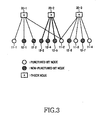
- FIG 3 is a diagram illustrating an exemplary factor graph for a description of terms defined in a puncturing method proposed in the present invention.
- the factor graph is based upon the parity check matrix and the factor graph of the LDPC code illustrated in FIGs. 1 and 2 .
- some of the bit nodes connected to check nodes 20-1 through 20-3 are non-punctured bit nodes 12-1 through 12-7, and the other bit nodes are punctured bit nodes 11-1 through 11-4.
- the non-punctured bit nodes 12-1 through 12-7 will be referred to as "0-step recoverable (0-SR) nodes," and for the check node 20-2 connected only to the 0-SR nodes 12-1 through 12-7, except for at least one punctured bit node 11-2 among the check nodes 20-1 through 20-3 connected through the edges, the punctured bit node 11-2 will be referred to as a "1-step recoverable (1-SR) node.”
- the 1-SR node is recoverable through one iterative decoding process during iterative decoding, and can be designated by a designer by randomly determining an initial puncturing pattern or taking into account a coding rate variation region or a characteristic of a mother code.
- a k-SR node becomes a recoverable node through k iterative decoding processes. This will be described mathematically in more detail below.
- the punctured bit node can be referred to as a k-step recoverable (k-SR) node.
- k-SR k-step recoverable
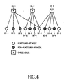
- FIG. 4 is a diagram illustrating an exemplary factor graph for a description of the k-SR node.
- at least one check node 35-2 among neighboring check nodes 35-1 through 35-3 includes one (k-1)-SR node 31-2 (recovered in a previous (k-1) th iterative decoding process) except for its k-SR node 31-3, and because the other connected bit nodes 32-3 and 32-4 will be the bit nodes (0-SR nodes in this embodiment) recovered in 0 th through (k-1) th iterative decoding processes, the punctured bit node 31-3 being adjacent to (connected to) the check node 35-2 will be classified as a k-SR node.
- k-SR k-step recoverable
- a 2-SR node must include a 1-SR node among the bit nodes connected to a check node given to determine a corresponding node as a 2-SR node among neighboring check nodes, and this means that the 1-SR node must be recovered in the previous decoding step in order to recover the 2-SR node.
- one of the check nodes being adjacent to the k-SR node must include a (k-1)-SR node recovered in the previous decoding step as described above, and the other bit nodes must also be fully decoded in any step of the previous decoding steps or must be a 0-SR node.
- a summary thereof is the k-SR node's definition described above.
- bit nodes are classified as step recoverable nodes one by one sequentially passing through decoding processes, and thereafter, are grouped according to nodes recoverable in the same step, it is preferable, for performance improvement, to sequentially perform puncturing on from a 1-SR node-group having the highest recovering possibility due to the fewer number of steps needed for decoding.
- the grouping up to this step it is possible to fully improve puncturing performance desired in the present invention.
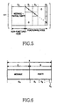
- FIG. 5 is a diagram illustrating a parity check matrix of an LDPC code, in which the grouped nodes are expressed as columns mapped to their associated nodes in the group order, and thereafter, arranged to have regularity for facilitation of hardware implementation.
- 1-SR nodes are classified as G 1 and k-SR nodes are classified as G k .
- columns of the parity check matrix are classified into G 0 through G k , and then, subject to column permutation so that the parity check matrix has regularity This is possible because a characteristic of the parity check matrix is constant even though the parity check matrix undergoes column permutation or row permutation, and it is preferable to design the parity check matrix such that it is simple in parity part, in order to reduce complexity.
- columns mapped to G 0 are columns mapped to the message and parity not to be punctured, correspond to the bit nodes not to be punctured, and columns mapped to G 1 correspond to the bit nodes to be punctured first and the parity belonging thereto can be recovered with one iteration in the iterative decoding when the channel is error-free.
- G 2 corresponds to the parities to be punctured after all of the parities mapped to the G 1 are punctured
- G 3 corresponds to the parities to be punctured after all of the parities mapped to the G 1 and G 2 are punctured
- G k corresponds to the parities to be punctured after all of the parities belonging to G 1 , G 2 , ..., G k-1 are punctured.
- FIG. 6 is a diagram illustrating a codeword that is coded through a generator matrix G generated using the parity check matrix H illustrated in FIG. 5 , or directly coded through the parity check matrix H.
- a codeword with a length N having a coding rate of the mother code coded by the parity check matrix H described above corresponds to systematic arrangement of the groups classified according to the present invention. That is, a message with a length K and a part of a parity with a length M are mapped to G 0 , the other parity parts are sequentially mapped to G 1 , G 2 , ..., G k according to their puncturing priorities, and a desired coding rate is achieved by puncturing the parity of the mother code. In this case, a puncturing length needed for the desired coding rate is calculated using Equation (1).
- N p N - K R p
- N denotes a codeword length of the mother code
- K denotes a message length of the mother code
- R p denotes a desired coding rate
- Np denotes a needed puncturing length
- the puncturing length N p needed at the desired coding rate is calculated, and then, the parities included in G 1 , G 2 , ..., G k are sequentially punctured by the corresponding length. Accordingly, the desired coding rate can be simply matched to any coding rate being higher than or equal to the coding rate of the mother code, and the same puncturing pattern in the fixed order of G 1 , G 2 , ..., G k is used at all coding rates, thereby supporting rate compatibility, so it can be applied to the H-ARQ technology.
- the 1-SR nodes can be recovered through 1-step iterative decoding, this is for the case where there is no error in a channel.
- AWGN additive white Gaussian noise
- the novel LDPC channel code puncturing method classifies parities included in the mother code into parity groups according to their puncturing priorities, arranges the parity groups in the puncturing order, and performs puncturing on the groups in order, thereby achieving a desiring coding rate. Accordingly, the puncturing method minimizes a loss due to the puncturing, thereby showing better performance than that of the random puncturing algorithm.
- the proposed code can show performance approximating that of the dedicated code that requires a plurality of encoder-decoder pairs, thereby contributing to a decrease in implementation complexity.
- the puncturing method can perform grouping on the parities to be punctured through a simple definition and an algorithm based thereon, and cope with a variation in coding rate through puncturing length adjustment for a desired coding rate, thereby offering high design and application conveniences as compared with the dedicated code that has high design complexity and has a limitation on possible coding rates.
- the proposed code uses the same puncturing order for all coding rates, it can be applied to the H-ARQ technology combined of retransmission and error correction functions, thereby contributing to an increase in error control performance as compared with the dedicated code that can be hardly applied to the H-ARQ technology.
Claims (7)
- Procédé pour retirer des bits de parité d'un code de contrôle de parité à faible densité, LDPC (pour "Low Density Parity Check"), qui est décodé au moyen d'une matrice de contrôle de parité exprimée par un graphe de facteurs incluant des noeuds de contrôle et des noeuds de bit connectés aux noeuds de contrôle par des arêtes, le procédé comprenant les étapes :de classification des noeuds de bit transposés en une partie de parité d'un mot de code dans des groupes hiérarchiques en fonction de leur possibilité de récupération ;de détermination d'un ordre de retrait des groupes hiérarchiques basé sur la possibilité de récupération ; etd'acquisition d'un mot de code avec un débit voulu de codage par retrait des noeuds de bit appartenant à un groupe hiérarchique correspondant choisi séquentiellement en fonction de l'ordre déterminé de retrait ;dans lequel la possibilité de récupération d'un noeud de bit est déterminée en se basant sur le nombre d'itérations nécessaires pour récupérer le noeud de bit retiré respectif lorsque la voie est exempte d'erreurs.
- Procédé selon la revendication 1, dans lequel à mesure que le nombre d'itérations diminue, le noeud de bit correspondant est classé dans un groupe hiérarchique ayant une priorité plus élevée de retrait.
- Procédé selon la revendication 1, dans lequel, s'il y a un noeud de contrôle connecté seulement à des noeuds de bit qui ne sont pas à retirer, excepté pour son noeud de bit à retirer, parmi les noeuds de contrôle connectés au noeud de bit à retirer, le noeud de bit à retirer est classé dans un groupe ayant la priorité la plus élevée de retrait.
- Procédé selon la revendication 1, dans lequel, s'il y a un noeud de contrôle connecté seulement à des noeuds de bit qui sont l'un des noeuds de bit récupérables au cours d'un processus antérieur de décodage itératif ou des noeuds de bit qui ne sont pas à retirer, excepté pour son noeud de bit à retirer parmi les noeuds de contrôle connectés au noeud de bit à retirer, le nombre d'itérations nécessaires pour la récupération dans le processus de décodage itératif lorsque la voie est exempte d'erreurs est utilisé comme critère pour classer le noeud de bit à retirer dans le groupe correspondant.
- Procédé selon la revendication 4, dans lequel au moins l'un des noeuds de bit connectés au noeud de contrôle est un noeud de bit récupérable à partir de l'itération immédiatement précédente dans le processus de décodage itératif.
- Procédé selon l'une des revendications 1 à 3, comprenant en outre l'étape de création d'une matrice de contrôle de parité dans laquelle l'ordre de retrait est pris en compte dans l'agencement de colonnes d'une matrice de contrôle de parité correspondant à l'ordre déterminé de retrait.
- Procédé selon la revendication 6, comprenant en outre l'étape d'exécution d'une permutation de colonnes de façon qu'une partie des groupes susceptibles d'être retirés dans une partie de parité de la matrice de contrôle de parité dans laquelle l'ordre de retrait est pris en compte forme une matrice d'identité.
Applications Claiming Priority (2)
| Application Number | Priority Date | Filing Date | Title |
|---|---|---|---|
| US62247304P | 2004-10-27 | 2004-10-27 | |
| KR1020050039919A KR100640399B1 (ko) | 2004-10-27 | 2005-05-12 | 저밀도 패리티 검사 채널 부호의 천공 방법 |
Publications (2)
| Publication Number | Publication Date |
|---|---|
| EP1653629A1 EP1653629A1 (fr) | 2006-05-03 |
| EP1653629B1 true EP1653629B1 (fr) | 2008-02-20 |
Family
ID=35636805
Family Applications (1)
| Application Number | Title | Priority Date | Filing Date |
|---|---|---|---|
| EP05023563A Active EP1653629B1 (fr) | 2004-10-27 | 2005-10-27 | Méthod de poinçonnage de codes LDPC |
Country Status (2)
| Country | Link |
|---|---|
| EP (1) | EP1653629B1 (fr) |
| DE (1) | DE602005004863T2 (fr) |
Cited By (1)
| Publication number | Priority date | Publication date | Assignee | Title |
|---|---|---|---|---|
| RU2450442C2 (ru) * | 2008-02-18 | 2012-05-10 | Самсунг Электроникс Ко., Лтд. | Способ и устройство для кодирования и декодирования канала в системе связи с использованием кодов с низкой плотностью проверок на четность |
Families Citing this family (6)
| Publication number | Priority date | Publication date | Assignee | Title |
|---|---|---|---|---|
| KR101157246B1 (ko) * | 2005-05-16 | 2012-06-15 | 삼성전자주식회사 | 저밀도 패리티 검사 부호의 패딩 및 천공 방법 |
| KR100943623B1 (ko) * | 2005-09-30 | 2010-02-24 | 삼성전자주식회사 | 저밀도 패러티 검사 부호의 천공기법 |
| KR20070080392A (ko) | 2006-02-07 | 2007-08-10 | 삼성전자주식회사 | 저밀도 패러티 검사 부호의 천공 방법 |
| WO2009104898A2 (fr) | 2008-02-18 | 2009-08-27 | Samsung Electronics Co., Ltd. | Appareil et procédé de codage et de décodage de canal dans un système de communication utilisant des codes de contrôle de parité à faible densité |
| KR100964610B1 (ko) | 2008-04-18 | 2010-06-21 | 한국전자통신연구원 | 오류정정 부호를 이용한 다이버시티 방법 |
| CN101877138B (zh) * | 2009-04-30 | 2014-01-15 | 国际商业机器公司 | 动态图的动画规划方法和装置 |
Family Cites Families (1)
| Publication number | Priority date | Publication date | Assignee | Title |
|---|---|---|---|---|
| EP1589663A1 (fr) * | 2004-04-22 | 2005-10-26 | Samsung Electronics Co., Ltd. | Système, appareil et procédé pour transmettre et recevoir des données codées par LDPC avec un taux de codage variable. |
-
2005
- 2005-10-27 DE DE200560004863 patent/DE602005004863T2/de active Active
- 2005-10-27 EP EP05023563A patent/EP1653629B1/fr active Active
Non-Patent Citations (1)
| Title |
|---|
| None * |
Cited By (1)
| Publication number | Priority date | Publication date | Assignee | Title |
|---|---|---|---|---|
| RU2450442C2 (ru) * | 2008-02-18 | 2012-05-10 | Самсунг Электроникс Ко., Лтд. | Способ и устройство для кодирования и декодирования канала в системе связи с использованием кодов с низкой плотностью проверок на четность |
Also Published As
| Publication number | Publication date |
|---|---|
| DE602005004863D1 (de) | 2008-04-03 |
| EP1653629A1 (fr) | 2006-05-03 |
| DE602005004863T2 (de) | 2009-02-19 |
Similar Documents
| Publication | Publication Date | Title |
|---|---|---|
| US7657824B2 (en) | Method for puncturing an LDPC channel code | |
| EP1596501B1 (fr) | Dispositif et procédé pour le codage et le décodage de codes LDPC de longueur variable | |
| US7882414B2 (en) | Apparatus and method for transmitting/receiving signal supporting variable coding rate in a communication system | |
| CN101689866B (zh) | 低密度奇偶校验卷积码编码器和低密度奇偶校验卷积码解码器 | |
| US8020062B2 (en) | Apparatus and method of encoding/decoding block low density parity check codes in a communication system | |
| US7734988B2 (en) | Method for puncturing a low density parity check code | |
| EP1576733B1 (fr) | Codes de controle de parite basse densite (ldcp) compatibles avec le debit | |
| US7526717B2 (en) | Apparatus and method for coding and decoding semi-systematic block low density parity check codes | |
| US7743312B2 (en) | Method for puncturing low density parity check code | |
| KR100881002B1 (ko) | 통신 시스템에서 지그재그 코드를 이용한 저밀도 패리티 검사 부호 생성 장치 및 방법 | |
| US20040268205A1 (en) | Low-density parity-check codes for multiple code rates | |
| EP1653629B1 (fr) | Méthod de poinçonnage de codes LDPC | |
| US20110164705A1 (en) | Bit mapping scheme for an ldpc coded 32apsk system | |
| EP1901433A1 (fr) | Famille de codes LDPC pour applications de diffusion de vidéo | |
| US8468430B2 (en) | Product code decoding method and device | |
| US20080155385A1 (en) | Apparatus and method to encode/decode block low density parity check codes in a communication system | |
| US11646818B2 (en) | Method and apparatus for encoding/decoding channel in communication or broadcasting system | |
| US11791845B2 (en) | Method and apparatus for channel encoding and decoding in communication or broadcasting system | |
| US20150280744A1 (en) | Decoding apparatus and method in mobile communication system using non-binary low-density parity-check code | |
| Inaba et al. | Reliability-based hybrid ARQ (RB-HARQ) schemes using low-density parity-check (LDPC) codes | |
| KR20080084058A (ko) | 모델 행렬을 이용하여 ldpc 부호화를 수행한 데이터를천공하는 방법 | |
| WO2008034288A1 (fr) | Schéma de mappage binaire pour système 16apsk codé par ldpc | |
| US20110173509A1 (en) | Bit mapping scheme for an ldpc coded 16apsk system |
Legal Events
| Date | Code | Title | Description |
|---|---|---|---|
| PUAI | Public reference made under article 153(3) epc to a published international application that has entered the european phase |
Free format text: ORIGINAL CODE: 0009012 |
|
| 17P | Request for examination filed |
Effective date: 20051027 |
|
| AK | Designated contracting states |
Kind code of ref document: A1 Designated state(s): AT BE BG CH CY CZ DE DK EE ES FI FR GB GR HU IE IS IT LI LT LU LV MC NL PL PT RO SE SI SK TR |
|
| AX | Request for extension of the european patent |
Extension state: AL BA HR MK YU |
|
| 17Q | First examination report despatched |
Effective date: 20060731 |
|
| AKX | Designation fees paid |
Designated state(s): DE FI FR GB SE |
|
| GRAP | Despatch of communication of intention to grant a patent |
Free format text: ORIGINAL CODE: EPIDOSNIGR1 |
|
| GRAS | Grant fee paid |
Free format text: ORIGINAL CODE: EPIDOSNIGR3 |
|
| GRAA | (expected) grant |
Free format text: ORIGINAL CODE: 0009210 |
|
| AK | Designated contracting states |
Kind code of ref document: B1 Designated state(s): DE FI FR GB SE |
|
| REG | Reference to a national code |
Ref country code: GB Ref legal event code: FG4D |
|
| REF | Corresponds to: |
Ref document number: 602005004863 Country of ref document: DE Date of ref document: 20080403 Kind code of ref document: P |
|
| REG | Reference to a national code |
Ref country code: SE Ref legal event code: TRGR |
|
| ET | Fr: translation filed | ||
| PLBE | No opposition filed within time limit |
Free format text: ORIGINAL CODE: 0009261 |
|
| STAA | Information on the status of an ep patent application or granted ep patent |
Free format text: STATUS: NO OPPOSITION FILED WITHIN TIME LIMIT |
|
| 26N | No opposition filed |
Effective date: 20081121 |
|
| REG | Reference to a national code |
Ref country code: FR Ref legal event code: PLFP Year of fee payment: 12 |
|
| REG | Reference to a national code |
Ref country code: FR Ref legal event code: PLFP Year of fee payment: 13 |
|
| REG | Reference to a national code |
Ref country code: FR Ref legal event code: PLFP Year of fee payment: 14 |
|
| PGFP | Annual fee paid to national office [announced via postgrant information from national office to epo] |
Ref country code: GB Payment date: 20230914 Year of fee payment: 19 |
|
| PGFP | Annual fee paid to national office [announced via postgrant information from national office to epo] |
Ref country code: SE Payment date: 20230926 Year of fee payment: 19 Ref country code: FR Payment date: 20230921 Year of fee payment: 19 |
|
| PGFP | Annual fee paid to national office [announced via postgrant information from national office to epo] |
Ref country code: FI Payment date: 20231011 Year of fee payment: 19 Ref country code: DE Payment date: 20230919 Year of fee payment: 19 |