EP1653122A1 - Belt drive for a harvester with a movable cutter. - Google Patents
Belt drive for a harvester with a movable cutter. Download PDFInfo
- Publication number
- EP1653122A1 EP1653122A1 EP05110060A EP05110060A EP1653122A1 EP 1653122 A1 EP1653122 A1 EP 1653122A1 EP 05110060 A EP05110060 A EP 05110060A EP 05110060 A EP05110060 A EP 05110060A EP 1653122 A1 EP1653122 A1 EP 1653122A1
- Authority
- EP
- European Patent Office
- Prior art keywords
- pulley
- belt
- length
- pulleys
- movable pulley
- Prior art date
- Legal status (The legal status is an assumption and is not a legal conclusion. Google has not performed a legal analysis and makes no representation as to the accuracy of the status listed.)
- Granted
Links
- 230000033001 locomotion Effects 0.000 claims abstract description 30
- 230000007423 decrease Effects 0.000 claims description 4
- 238000006073 displacement reaction Methods 0.000 claims description 4
- 238000010276 construction Methods 0.000 description 2
- 241001124569 Lycaenidae Species 0.000 description 1
- 230000005540 biological transmission Effects 0.000 description 1
- 239000004459 forage Substances 0.000 description 1
- 230000002452 interceptive effect Effects 0.000 description 1
Images

Classifications
-
- F—MECHANICAL ENGINEERING; LIGHTING; HEATING; WEAPONS; BLASTING
- F16—ENGINEERING ELEMENTS AND UNITS; GENERAL MEASURES FOR PRODUCING AND MAINTAINING EFFECTIVE FUNCTIONING OF MACHINES OR INSTALLATIONS; THERMAL INSULATION IN GENERAL
- F16H—GEARING
- F16H7/00—Gearings for conveying rotary motion by endless flexible members
- F16H7/08—Means for varying tension of belts, ropes, or chains
- F16H7/10—Means for varying tension of belts, ropes, or chains by adjusting the axis of a pulley
- F16H7/12—Means for varying tension of belts, ropes, or chains by adjusting the axis of a pulley of an idle pulley
-
- A—HUMAN NECESSITIES
- A01—AGRICULTURE; FORESTRY; ANIMAL HUSBANDRY; HUNTING; TRAPPING; FISHING
- A01D—HARVESTING; MOWING
- A01D41/00—Combines, i.e. harvesters or mowers combined with threshing devices
- A01D41/12—Details of combines
- A01D41/14—Mowing tables
- A01D41/142—Header drives
-
- A—HUMAN NECESSITIES
- A01—AGRICULTURE; FORESTRY; ANIMAL HUSBANDRY; HUNTING; TRAPPING; FISHING
- A01D—HARVESTING; MOWING
- A01D69/00—Driving mechanisms or parts thereof for harvesters or mowers
Definitions
- the present invention relates to a belt drive for a harvester with a movable cutter.
- One type of header that is fitted to combine and forage harvesters comprises a reel that extends transversely to the direction of travel.
- a scissor-action cutter located beneath the reel cuts the stalks of the crop, spring tines projecting from the rotating reel pick up the cut crop and pushes them on to two augers that advance the crop towards the centre of the harvester. From there, the crop is carried into the processing machinery of the harvester.
- the ideal distance between the cutter and the auger depends on the type of crop being harvested and it is known to mount the cutter in such a manner that it can be moved forwards and backwards relative to the auger.
- the cutter is formed of two blades, one being movable in a reciprocated movement relative to the other by means of a so-called wobble box, the cutter and its drive mechanism being mounted on a sub-frame that can be moved relative to the main frame of the header by some 50 cms, typically.
- the wobble box has a drive pulley that is driven by a belt which passes over a stationary powered pulley mounted on the main frame of the header. A belt configuration is therefore required which does not obstruct the movement of the cutter sub-frame yet which maintains the drive belt under the correct tension to drive the wobble box in all positions of the cutter sub-frame.
- the geometry of the belt drive for a movable cutter of a harvester is further complicated by the magnitude of the permissible movement because it is necessary to ensure that the different runs of the belt never touch one another in any position of the cutter sub-frame. Furthermore, the belt and its various drive, guide and tensioning pulleys must all remain protected within a housing that covers the entire drive mechanism to prevent entanglement of the crop.
- a belt drive for connecting a stationary pulley to a relatively movable pulley, comprising a first guide pulley mounted in a fixed position in relation to the stationary pulley and a second guide pulley mounted for movement with the movable pulley, characterised in that the second guide pulley is mounted in such a manner as to be capable of a limited degree of movement relative to the movable pulley and is spring biased in a direction to maintain the belt in tension.
- the first guide pulley that is to say the one mounted on the same frame as the stationary pulley, was used as the belt tensioner.
- the axle of the tensioning pulley was supported for movement along two parallel guide tracks which made for a complex and costly construction.
- the second guide pulley that is mounted for movement with the movable pulley is the one that is used as the belt tensioning pulley.
- Such mounting of the tensioning pulley makes for a simpler and more compact construction in that the movement of the tensioning pulley need no longer be rectilinear.
- the second guide pulley is carried on one end of a lever arm that is pivotably mounted on a sub-frame supporting the movable pulley, the opposite end of the lever being acted upon by a spring acting to rotate the lever arm in a direction to increase the belt tension. Since these changes in length of the belt occur during the lifetime of the belt and the tensioning of the belt is done automatically by the spring biased rod, the driver does not need to follow up the stretching of the belt or take care of it.
- the path traced by the belt around the pulleys includes two runs that change in length during displacement of the movable pulley.
- the relative positions of the pulleys are such that while the length of one of these two runs increases the length of the other decreases by a substantially equal amount, whereby the length of the path traced by the belt does not change significantly with the position of the movable pulley relative to the stationary pulley.
- the amount of movement required of the belt tensioner pulley in order to take up the slack in the belt is reduced.
- the distance between the stationary and movable pulleys may be too long when the cutter is moved into its most forward position to be spanned by a single run of the belt. It is therefore advantageous to provide two support pulleys to contact the opposite sides of the run of the belt that extends from the stationary pulley to the movable pulley.
- one of the support pulleys may be stationary and the other movable with the movable pulley, the run extending between the two support pulleys being one of the two runs of varying length.
- a belt drive for connecting a stationary pulley to a relatively movable pulley comprising a first guide pulley mounted in a fixed position in relation to the stationary pulley and a second guide pulley mounted for movement with the movable pulley, characterised in that the path traced by the belt around the pulleys includes two runs that change in length during displacement of the movable pulley and in that the relative positions of the pulleys are such that while the length of one of said two runs increases the length of the other decreases by a substantially equal amount, whereby the length of the path traced by the belt does not change significantly with the position of the movable pulley relative to the stationary pulley.
- a drive pulley 10 is mounted on the frame of the header of a harvester and is connected by a chain and sprocket transmission (not shown) for rotation with the auger of the header.
- a driven pulley 12 is mounted on a sub-frame 15 which is movable relative to the frame of the header. The pulley 12 is fitted to the input shaft of a wobble box that reciprocates one of the blades of the cutter.
- a first guide pulley 14 is mounted on the frame of the header and a second guide pulley 16 is mounted on the movable sub-frame 15.
- the pulleys 20 and 22 supporting the run of the belt 18 between the pulleys 12 and 16 are mounted on the movable sub-frame 15 whereas of the two pulleys 24 and 26 supporting the run of the belt 18 extending between the pulleys 12 and 10, the pulley 24 is mounted on the sub-frame 15 and the pulley 26 is stationarily mounted on the frame of the header.
- the guide pulley 14 acts as a tensioning pulley and its axle 28 is guided for movement along slots 30 in a bracket 34 that is secured to the frame of the header.
- the axle of the pulley 14 is received in a clevis that slides along the slots 30 and is connected to a rod 36 that applies a spring bias to the axle to maintain the belt 18 in tension in all positions of the pulley 12.
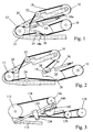
- the embodiment of the invention differs from the prior art belt drive shown in Figures 1 and 2 in that the run that extends between the pulleys 112 and 116 does not require the addition of a support pulley as it does not risk to interfere with any other part of the belt drive in any position of the sub-frame 115. All the remaining pulleys do however have counterparts in the embodiment of Figures 3 to 5.
- the pulley 114 is directly mounted on the frame of the header and it is the pulley 116 that acts as the tensioning pulley for the belt 118.
- the pulley 116 is not guided for rectilinear motion but is instead carried by a lever arm 140 which is pivoted at its centre on the sub-frame 115.
- the axle of the pulley 116 is mounted on one end of the lever arm 140 and the other end of the lever arm 140 is connected to a clevis 142 on one end of a spring biased rod 144 which biases the lever arm 140 in a clockwise direction to maintain the belt 118 under tension.
- a further important difference resides in the geometry of the pulleys. If the runs 118a and 118b were to lie parallel to one another and parallel to the direction of movement of the pulley 112, there would be no change in the length of the path traced by the belt 118 in the different positions of the sub-frame 115. Because this is difficult to achieve, on account of the need to support the run of the belt between the pulley 110 and 112, the two variable length runs 118a and 118b are instead inclined at the same shallow angle as one another to the direction of movement to direction movement of the sub-frame. Consequently, during movement of the sub-frame 115, these two runs 118a and 118b change length by substantially equal amounts, with the one being lengthened as the other is shortened.
Landscapes
- Life Sciences & Earth Sciences (AREA)
- Environmental Sciences (AREA)
- Engineering & Computer Science (AREA)
- General Engineering & Computer Science (AREA)
- Mechanical Engineering (AREA)
- Harvester Elements (AREA)
- Devices For Conveying Motion By Means Of Endless Flexible Members (AREA)
- Perforating, Stamping-Out Or Severing By Means Other Than Cutting (AREA)
- Treatment Of Fiber Materials (AREA)
- Auxiliary Devices For And Details Of Packaging Control (AREA)
- Harvesting Machines For Specific Crops (AREA)
Abstract
Description
- The present invention relates to a belt drive for a harvester with a movable cutter.
- One type of header that is fitted to combine and forage harvesters comprises a reel that extends transversely to the direction of travel. A scissor-action cutter located beneath the reel cuts the stalks of the crop, spring tines projecting from the rotating reel pick up the cut crop and pushes them on to two augers that advance the crop towards the centre of the harvester. From there, the crop is carried into the processing machinery of the harvester.
- The ideal distance between the cutter and the auger depends on the type of crop being harvested and it is known to mount the cutter in such a manner that it can be moved forwards and backwards relative to the auger. The cutter is formed of two blades, one being movable in a reciprocated movement relative to the other by means of a so-called wobble box, the cutter and its drive mechanism being mounted on a sub-frame that can be moved relative to the main frame of the header by some 50 cms, typically. The wobble box has a drive pulley that is driven by a belt which passes over a stationary powered pulley mounted on the main frame of the header. A belt configuration is therefore required which does not obstruct the movement of the cutter sub-frame yet which maintains the drive belt under the correct tension to drive the wobble box in all positions of the cutter sub-frame.
- The geometry of the belt drive for a movable cutter of a harvester is further complicated by the magnitude of the permissible movement because it is necessary to ensure that the different runs of the belt never touch one another in any position of the cutter sub-frame. Furthermore, the belt and its various drive, guide and tensioning pulleys must all remain protected within a housing that covers the entire drive mechanism to prevent entanglement of the crop.
- Prior art attempts to meet the above criteria have resulted in belt geometries having as many as eight different pulleys and, despite their complexity, holes were needed in the frame to allow pulleys to be repositioned to achieve the desired belt tension in different positions of the cutter.
- In accordance with a first aspect of the present invention, there is provided a belt drive for connecting a stationary pulley to a relatively movable pulley, comprising a first guide pulley mounted in a fixed position in relation to the stationary pulley and a second guide pulley mounted for movement with the movable pulley, characterised in that the second guide pulley is mounted in such a manner as to be capable of a limited degree of movement relative to the movable pulley and is spring biased in a direction to maintain the belt in tension.
- In the prior art, the first guide pulley, that is to say the one mounted on the same frame as the stationary pulley, was used as the belt tensioner. To avoid its interfering with components mounted on the same sub-frame as the movable pulley, this necessitated that the movement of the tensioning pulley should be confined to a rectilinear motion. To achieve this, the axle of the tensioning pulley was supported for movement along two parallel guide tracks which made for a complex and costly construction.
- In the present invention, the second guide pulley that is mounted for movement with the movable pulley is the one that is used as the belt tensioning pulley. Such mounting of the tensioning pulley makes for a simpler and more compact construction in that the movement of the tensioning pulley need no longer be rectilinear.
- Conveniently, the second guide pulley is carried on one end of a lever arm that is pivotably mounted on a sub-frame supporting the movable pulley, the opposite end of the lever being acted upon by a spring acting to rotate the lever arm in a direction to increase the belt tension. Since these changes in length of the belt occur during the lifetime of the belt and the tensioning of the belt is done automatically by the spring biased rod, the driver does not need to follow up the stretching of the belt or take care of it.
- The path traced by the belt around the pulleys includes two runs that change in length during displacement of the movable pulley. In preferred embodiment of the invention, the relative positions of the pulleys are such that while the length of one of these two runs increases the length of the other decreases by a substantially equal amount, whereby the length of the path traced by the belt does not change significantly with the position of the movable pulley relative to the stationary pulley.
- If the length of the path traced by the belt does not vary significantly with movement of the movable pulley, the amount of movement required of the belt tensioner pulley in order to take up the slack in the belt is reduced.
- Because of the extent of possible movement of the cutter, the distance between the stationary and movable pulleys may be too long when the cutter is moved into its most forward position to be spanned by a single run of the belt. It is therefore advantageous to provide two support pulleys to contact the opposite sides of the run of the belt that extends from the stationary pulley to the movable pulley.
- In this case, one of the support pulleys may be stationary and the other movable with the movable pulley, the run extending between the two support pulleys being one of the two runs of varying length.
- In accordance with a second aspect of the invention, there is provided a belt drive for connecting a stationary pulley to a relatively movable pulley, comprising a first guide pulley mounted in a fixed position in relation to the stationary pulley and a second guide pulley mounted for movement with the movable pulley, characterised in that the path traced by the belt around the pulleys includes two runs that change in length during displacement of the movable pulley and in that the relative positions of the pulleys are such that while the length of one of said two runs increases the length of the other decreases by a substantially equal amount, whereby the length of the path traced by the belt does not change significantly with the position of the movable pulley relative to the stationary pulley.
- The invention will now be described further, by way of example, with reference to the accompanying drawings, in which:
- Figure 1 is a schematic representation of a known belt drive for a harvester header having a movable cutter,
- Figure 2 shows the belt drive of Figure 1 when the cutter is moved forwards,
- Figure 3 is a similar schematic representation of a belt drive of the invention, and
- Figures 4 and 5 are views of parts of the belt drive shown in Figure 3, drawn to an enlarged scale, showing the configuration of the belt drive in different positions of the movable pulley.
- In Figures 1 and 2, a
drive pulley 10 is mounted on the frame of the header of a harvester and is connected by a chain and sprocket transmission (not shown) for rotation with the auger of the header. A drivenpulley 12 is mounted on asub-frame 15 which is movable relative to the frame of the header. Thepulley 12 is fitted to the input shaft of a wobble box that reciprocates one of the blades of the cutter. Afirst guide pulley 14 is mounted on the frame of the header and asecond guide pulley 16 is mounted on themovable sub-frame 15. Thebelt 18, if passing only around the above four pulleys mentioned above, would include two long runs from thepulley 12 to thepulleys belt 18 along these two runs, they are each guided over a respective pair of support pulleys. Thepulleys belt 18 between thepulleys movable sub-frame 15 whereas of the twopulleys belt 18 extending between thepulleys pulley 24 is mounted on thesub-frame 15 and thepulley 26 is stationarily mounted on the frame of the header. - The
guide pulley 14 acts as a tensioning pulley and itsaxle 28 is guided for movement alongslots 30 in abracket 34 that is secured to the frame of the header. The axle of thepulley 14 is received in a clevis that slides along theslots 30 and is connected to arod 36 that applies a spring bias to the axle to maintain thebelt 18 in tension in all positions of thepulley 12. - A comparison of Figures 1 and 2 will show that when the
sub-frame 15 and the various pulleys mounted on it are moved, only two runs of the belt change in length, namely therun 18a that extends between thepulleys run 18b that extends between thepulleys sub-frame 15 moves. The tensioningroller 14 needs therefore a considerable degree of travel to take up the slack created in the belt. This is in addition to the movement of thetensioning pulley 16 that is required to compensate for stretching of thebelt 18 as it ages. For this reason, in the prior art, in addition to providinglong slots 30 for the movement ofpulley 14, holes (not shown) were provided into thesub-frame 15 to allow thepulley 16 to be repositioned when necessary. - It will also be noted, from Figure 1 in particular, that the space in which one can accommodate a tensioning pulley capable of a large degree of travel is severely limited and consequently, the
tensioning pulley 14 needs to be guided for linear movement. - In the embodiment of the invention now to be described with reference to Figures 3 to 5, in order to avoid unnecessary repetition, items that serve the same function as described with reference to Figures 1 and 2 have been allocated the same reference numerals in the one hundred series (i.e. 100 has been added to the numerical values of each reference numeral).
- The embodiment of the invention differs from the prior art belt drive shown in Figures 1 and 2 in that the run that extends between the
pulleys sub-frame 115. All the remaining pulleys do however have counterparts in the embodiment of Figures 3 to 5. - An important difference between the embodiment of the invention and the prior art is that in this case the
pulley 114 is directly mounted on the frame of the header and it is thepulley 116 that acts as the tensioning pulley for thebelt 118. Furthermore, thepulley 116 is not guided for rectilinear motion but is instead carried by alever arm 140 which is pivoted at its centre on thesub-frame 115. The axle of thepulley 116 is mounted on one end of thelever arm 140 and the other end of thelever arm 140 is connected to aclevis 142 on one end of a springbiased rod 144 which biases thelever arm 140 in a clockwise direction to maintain thebelt 118 under tension. - A further important difference resides in the geometry of the pulleys. If the
runs pulley 112, there would be no change in the length of the path traced by thebelt 118 in the different positions of thesub-frame 115. Because this is difficult to achieve, on account of the need to support the run of the belt between thepulley sub-frame 115, these two runs 118a and 118b change length by substantially equal amounts, with the one being lengthened as the other is shortened. The little variation in the attitude of these runs in the different positions of thesub-frame 115 shown in Figures 3 to 5 is to be contrasted with the significant variation that occurs between Figures 1 and 2 in the prior art. As a result of this design, the movement of thepulley 116 to tension the belt is required predominantly to compensate for stretching of the belt with age, not for the slack that is created and taken up as thesub-frame 115 moves.
Claims (6)
- A belt drive for connecting a stationary pulley (110) to a relatively movable pulley (112), comprising a first guide pulley (114) mounted in a fixed position in relation to the stationary pulley (110) and a second guide pulley (116) mounted for movement with the movable pulley (112), characterised in that the second guide pulley (116) is mounted in such a manner as to be capable of a limited degree of movement relative to the movable pulley (112) and is spring biased in a direction to maintain the belt (118) in tension.
- A belt drive as claimed in claim 1, wherein the second guide pulley (116) is carried on one end of a lever arm (140) that is pivotably mounted on a sub-frame (115) supporting the movable pulley (112), the opposite end of the lever (140) being acted upon by a spring (144) acting to rotate the lever arm (140) in a direction to increase the belt tension.
- A belt drive as claimed in claim 1 or 2, wherein the path traced by the belt (118) around the pulleys (110, 112,114,116) includes two runs (118a,118b) that change in length during displacement of the movable pulley (112) and wherein the relative positions of the pulleys (110,112,114, 116) are such that while the length of one of said two runs (118a) increases the length of the other (118b) decreases by a substantially equal amount, whereby the length of the path traced by the belt (118) does not change significantly with the position of the movable pulley (112) relative to the stationary pulley (110).
- A belt drive as claimed in any preceding claim, wherein two support pulleys (124,126)are provided to contact the opposite sides of the run of the belt (118) that extends from the stationary pulley (110) to the movable pulley (112).
- A belt drive as claimed in claim 4, wherein one (126) of the support pulleys is stationary and the other (124) movable with the movable pulley (112), the run (118b) extending between the two support pulleys (124,126) being one of the two runs of varying length.
- A belt drive for connecting a stationary pulley (110) to a relatively movable pulley (112), comprising a first guide pulley (114) mounted in a fixed position in relation to the stationary pulley (110) and a second guide pulley (116) mounted for movement with the movable pulley (112), characterised in that the path traced by the belt (118) around the pulleys (110,112,114,116) includes two runs (118a,118b) that change in length during displacement of the movable pulley (112) and in that the relative positions of the pulleys (110,112,114,116) are such that while the length of one (118a) of said two runs increases the length of the other (118b) decreases by a substantially equal amount, whereby the length of the path traced by the belt (118) does not change significantly with the position of the movable pulley (112) relative to the stationary pulley (110).
Applications Claiming Priority (1)
| Application Number | Priority Date | Filing Date | Title |
|---|---|---|---|
| GB0423798A GB2419650A (en) | 2004-10-27 | 2004-10-27 | Belt drive for a harvester with a movable cutter |
Publications (2)
| Publication Number | Publication Date |
|---|---|
| EP1653122A1 true EP1653122A1 (en) | 2006-05-03 |
| EP1653122B1 EP1653122B1 (en) | 2008-10-08 |
Family
ID=33515598
Family Applications (1)
| Application Number | Title | Priority Date | Filing Date |
|---|---|---|---|
| EP05110060A Active EP1653122B1 (en) | 2004-10-27 | 2005-10-27 | Belt drive for a harvester with a movable cutter. |
Country Status (6)
| Country | Link |
|---|---|
| US (1) | US20060089219A1 (en) |
| EP (1) | EP1653122B1 (en) |
| AT (1) | ATE410621T1 (en) |
| DE (1) | DE602005010181D1 (en) |
| DK (1) | DK1653122T3 (en) |
| GB (1) | GB2419650A (en) |
Cited By (5)
| Publication number | Priority date | Publication date | Assignee | Title |
|---|---|---|---|---|
| EP2147589A1 (en) | 2008-07-22 | 2010-01-27 | CNH Belgium N.V. | Belt drive for a harvesting header with a movable cutterbar |
| WO2011098479A1 (en) | 2010-02-09 | 2011-08-18 | Cnh Belgium N.V. | Header of a harvester |
| DE102016212646A1 (en) | 2016-07-12 | 2018-01-18 | Deere & Company | Drive arrangement for driving a Mähwerksbalkens a cutting unit |
| DE102017220148A1 (en) | 2017-11-13 | 2019-05-16 | Deere & Company | Discharge device for a forage harvester |
| EP3571916A2 (en) | 2018-05-24 | 2019-11-27 | Deere & Company | Drive assembly for driving a mower beam of a cutting system |
Families Citing this family (6)
| Publication number | Priority date | Publication date | Assignee | Title |
|---|---|---|---|---|
| US20080276590A1 (en) * | 2006-02-10 | 2008-11-13 | Agco Corporation | Flexible draper and cutter bar with tilt arm for cutterbar drive |
| BR102013026992B1 (en) * | 2012-10-19 | 2020-01-07 | Cnh Industrial America Llc | AGRICULTURAL HARVESTER, FORCE TRANSMISSION SYSTEM AND METHOD OF MAINTAINING A PRESSURE ON A FLEXIBLE CONNECTION OF A FORCE TRANSMISSION SYSTEM |
| US9581224B1 (en) * | 2013-03-16 | 2017-02-28 | Eric N. Anderfaas | Final drive chain adjuster for single and multi track vehicles |
| BE1021999B1 (en) * | 2014-07-11 | 2016-02-03 | Cnh Industrial Belgium Nv | MOWER |
| BE1022840B1 (en) * | 2015-03-09 | 2016-09-20 | Cnh Industrial Belgium Nv | Mower for a harvesting machine that contains a movable cutter bar table |
| US11293529B2 (en) * | 2019-05-20 | 2022-04-05 | Deere & Company | Snowblower belt drive system |
Citations (5)
| Publication number | Priority date | Publication date | Assignee | Title |
|---|---|---|---|---|
| US4069650A (en) * | 1975-10-15 | 1978-01-24 | Massey-Ferguson Services N.V. | Crop gathering apparatus |
| EP0282311A2 (en) * | 1987-03-10 | 1988-09-14 | Tecumseh Products Company | Belt drive system |
| US5557912A (en) * | 1995-06-13 | 1996-09-24 | Western Combine Corporation | Stripper header attachment |
| US5769747A (en) * | 1996-09-05 | 1998-06-23 | Deere & Company | Belt tensioning mechanism with stop feature |
| US5778644A (en) * | 1996-08-09 | 1998-07-14 | Deere & Company | Crop harvesting platform having a reversible drive for the reel, cutterbar center-feed augers and conditioner rolls |
Family Cites Families (3)
| Publication number | Priority date | Publication date | Assignee | Title |
|---|---|---|---|---|
| US3643720A (en) * | 1970-08-26 | 1972-02-22 | Sperry Rand Corp | Forage harvester feed roll drive |
| SU718040A1 (en) * | 1978-08-08 | 1980-02-29 | Предприятие П/Я Р-6130 | Delivery conveyer to machines for picking and loading root and tuber crops |
| GB9926580D0 (en) * | 1999-11-11 | 2000-01-12 | Medicine | Crop processor and blower arrangement for a forage harvester |
-
2004
- 2004-10-27 GB GB0423798A patent/GB2419650A/en not_active Withdrawn
-
2005
- 2005-05-19 US US11/133,116 patent/US20060089219A1/en not_active Abandoned
- 2005-10-27 AT AT05110060T patent/ATE410621T1/en active
- 2005-10-27 DK DK05110060T patent/DK1653122T3/en active
- 2005-10-27 EP EP05110060A patent/EP1653122B1/en active Active
- 2005-10-27 DE DE602005010181T patent/DE602005010181D1/en active Active
Patent Citations (5)
| Publication number | Priority date | Publication date | Assignee | Title |
|---|---|---|---|---|
| US4069650A (en) * | 1975-10-15 | 1978-01-24 | Massey-Ferguson Services N.V. | Crop gathering apparatus |
| EP0282311A2 (en) * | 1987-03-10 | 1988-09-14 | Tecumseh Products Company | Belt drive system |
| US5557912A (en) * | 1995-06-13 | 1996-09-24 | Western Combine Corporation | Stripper header attachment |
| US5778644A (en) * | 1996-08-09 | 1998-07-14 | Deere & Company | Crop harvesting platform having a reversible drive for the reel, cutterbar center-feed augers and conditioner rolls |
| US5769747A (en) * | 1996-09-05 | 1998-06-23 | Deere & Company | Belt tensioning mechanism with stop feature |
Cited By (8)
| Publication number | Priority date | Publication date | Assignee | Title |
|---|---|---|---|---|
| EP2147589A1 (en) | 2008-07-22 | 2010-01-27 | CNH Belgium N.V. | Belt drive for a harvesting header with a movable cutterbar |
| US7730702B2 (en) | 2008-07-22 | 2010-06-08 | Cnh America Llc | Belt drive for a harvesting header with a movable cutterbar |
| WO2011098479A1 (en) | 2010-02-09 | 2011-08-18 | Cnh Belgium N.V. | Header of a harvester |
| DE102016212646A1 (en) | 2016-07-12 | 2018-01-18 | Deere & Company | Drive arrangement for driving a Mähwerksbalkens a cutting unit |
| US10356976B2 (en) | 2016-07-12 | 2019-07-23 | Deere & Company | Drive arrangement for driving a cutter bar of a cutting mechanism |
| DE102017220148A1 (en) | 2017-11-13 | 2019-05-16 | Deere & Company | Discharge device for a forage harvester |
| EP3571916A2 (en) | 2018-05-24 | 2019-11-27 | Deere & Company | Drive assembly for driving a mower beam of a cutting system |
| US11160209B2 (en) | 2018-05-24 | 2021-11-02 | Deere & Company | Hydraulic drive arrangement to drive a reciprocating cutter bar |
Also Published As
| Publication number | Publication date |
|---|---|
| GB2419650A (en) | 2006-05-03 |
| US20060089219A1 (en) | 2006-04-27 |
| DK1653122T3 (en) | 2008-11-10 |
| GB0423798D0 (en) | 2004-12-01 |
| EP1653122B1 (en) | 2008-10-08 |
| ATE410621T1 (en) | 2008-10-15 |
| DE602005010181D1 (en) | 2008-11-20 |
Similar Documents
| Publication | Publication Date | Title |
|---|---|---|
| EP1653122B1 (en) | Belt drive for a harvester with a movable cutter. | |
| US7730702B2 (en) | Belt drive for a harvesting header with a movable cutterbar | |
| AU2008202930B8 (en) | Reciprocating knife cutter system | |
| US8438823B2 (en) | Flexible draper belt drive for an agricultural harvesting machine | |
| US9781879B2 (en) | Timing apparatus for separately driven sickle knives | |
| JP2008072919A (en) | Combine harvester | |
| US3380313A (en) | Reel drive mechanism | |
| US11154007B2 (en) | Harvester cutterbar knife drive with cylindrical cam or self reversing lead screw mechanism | |
| US9538707B2 (en) | Harvester header with belt length adapting mechanism | |
| KR910006202B1 (en) | Header devices of combine | |
| JP3308172B2 (en) | Combine harvester slide structure | |
| JP3310562B2 (en) | Combine harvester | |
| SU1197581A1 (en) | Grain harvesting combine header | |
| JP2007300894A (en) | Reaping clutch mechanism | |
| JP3385571B2 (en) | Combine harvester | |
| JP2012170398A (en) | Reaping portion structure of general purpose combine harvester | |
| JP3567556B2 (en) | Combine slide harvester | |
| JP3452965B2 (en) | Combine harvester | |
| JP2022070660A (en) | combine | |
| JP2005211043A (en) | Combine harvester | |
| JPH10276546A (en) | Combine | |
| JP2020080716A (en) | Combine harvester | |
| JP2019118274A (en) | Combine-harvester | |
| JP2018102253A (en) | combine | |
| JP2005211044A (en) | Raking reel driving structure of combine harvester |
Legal Events
| Date | Code | Title | Description |
|---|---|---|---|
| PUAI | Public reference made under article 153(3) epc to a published international application that has entered the european phase |
Free format text: ORIGINAL CODE: 0009012 |
|
| AK | Designated contracting states |
Kind code of ref document: A1 Designated state(s): AT BE BG CH CY CZ DE DK EE ES FI FR GB GR HU IE IS IT LI LT LU LV MC NL PL PT RO SE SI SK TR |
|
| AX | Request for extension of the european patent |
Extension state: AL BA HR MK YU |
|
| 17P | Request for examination filed |
Effective date: 20060720 |
|
| 17Q | First examination report despatched |
Effective date: 20060825 |
|
| AKX | Designation fees paid |
Designated state(s): AT BE BG CH CY CZ DE DK EE ES FI FR GB GR HU IE IS IT LI LT LU LV MC NL PL PT RO SE SI SK TR |
|
| 17Q | First examination report despatched |
Effective date: 20060825 |
|
| 17Q | First examination report despatched |
Effective date: 20060825 |
|
| GRAP | Despatch of communication of intention to grant a patent |
Free format text: ORIGINAL CODE: EPIDOSNIGR1 |
|
| GRAS | Grant fee paid |
Free format text: ORIGINAL CODE: EPIDOSNIGR3 |
|
| GRAA | (expected) grant |
Free format text: ORIGINAL CODE: 0009210 |
|
| AK | Designated contracting states |
Kind code of ref document: B1 Designated state(s): AT BE BG CH CY CZ DE DK EE ES FI FR GB GR HU IE IS IT LI LT LU LV MC NL PL PT RO SE SI SK TR |
|
| REG | Reference to a national code |
Ref country code: GB Ref legal event code: FG4D |
|
| REG | Reference to a national code |
Ref country code: CH Ref legal event code: EP |
|
| REG | Reference to a national code |
Ref country code: DK Ref legal event code: T3 |
|
| REG | Reference to a national code |
Ref country code: IE Ref legal event code: FG4D |
|
| REF | Corresponds to: |
Ref document number: 602005010181 Country of ref document: DE Date of ref document: 20081120 Kind code of ref document: P |
|
| PG25 | Lapsed in a contracting state [announced via postgrant information from national office to epo] |
Ref country code: SI Free format text: LAPSE BECAUSE OF FAILURE TO SUBMIT A TRANSLATION OF THE DESCRIPTION OR TO PAY THE FEE WITHIN THE PRESCRIBED TIME-LIMIT Effective date: 20081008 |
|
| NLV1 | Nl: lapsed or annulled due to failure to fulfill the requirements of art. 29p and 29m of the patents act | ||
| PG25 | Lapsed in a contracting state [announced via postgrant information from national office to epo] |
Ref country code: LT Free format text: LAPSE BECAUSE OF FAILURE TO SUBMIT A TRANSLATION OF THE DESCRIPTION OR TO PAY THE FEE WITHIN THE PRESCRIBED TIME-LIMIT Effective date: 20081008 Ref country code: ES Free format text: LAPSE BECAUSE OF FAILURE TO SUBMIT A TRANSLATION OF THE DESCRIPTION OR TO PAY THE FEE WITHIN THE PRESCRIBED TIME-LIMIT Effective date: 20090119 Ref country code: BG Free format text: LAPSE BECAUSE OF FAILURE TO SUBMIT A TRANSLATION OF THE DESCRIPTION OR TO PAY THE FEE WITHIN THE PRESCRIBED TIME-LIMIT Effective date: 20090108 |
|
| PG25 | Lapsed in a contracting state [announced via postgrant information from national office to epo] |
Ref country code: MC Free format text: LAPSE BECAUSE OF NON-PAYMENT OF DUE FEES Effective date: 20081031 Ref country code: FI Free format text: LAPSE BECAUSE OF FAILURE TO SUBMIT A TRANSLATION OF THE DESCRIPTION OR TO PAY THE FEE WITHIN THE PRESCRIBED TIME-LIMIT Effective date: 20081008 Ref country code: NL Free format text: LAPSE BECAUSE OF FAILURE TO SUBMIT A TRANSLATION OF THE DESCRIPTION OR TO PAY THE FEE WITHIN THE PRESCRIBED TIME-LIMIT Effective date: 20081008 Ref country code: PL Free format text: LAPSE BECAUSE OF FAILURE TO SUBMIT A TRANSLATION OF THE DESCRIPTION OR TO PAY THE FEE WITHIN THE PRESCRIBED TIME-LIMIT Effective date: 20081008 Ref country code: PT Free format text: LAPSE BECAUSE OF FAILURE TO SUBMIT A TRANSLATION OF THE DESCRIPTION OR TO PAY THE FEE WITHIN THE PRESCRIBED TIME-LIMIT Effective date: 20090218 Ref country code: LV Free format text: LAPSE BECAUSE OF FAILURE TO SUBMIT A TRANSLATION OF THE DESCRIPTION OR TO PAY THE FEE WITHIN THE PRESCRIBED TIME-LIMIT Effective date: 20081008 Ref country code: IS Free format text: LAPSE BECAUSE OF FAILURE TO SUBMIT A TRANSLATION OF THE DESCRIPTION OR TO PAY THE FEE WITHIN THE PRESCRIBED TIME-LIMIT Effective date: 20090208 |
|
| PG25 | Lapsed in a contracting state [announced via postgrant information from national office to epo] |
Ref country code: EE Free format text: LAPSE BECAUSE OF FAILURE TO SUBMIT A TRANSLATION OF THE DESCRIPTION OR TO PAY THE FEE WITHIN THE PRESCRIBED TIME-LIMIT Effective date: 20081008 Ref country code: RO Free format text: LAPSE BECAUSE OF FAILURE TO SUBMIT A TRANSLATION OF THE DESCRIPTION OR TO PAY THE FEE WITHIN THE PRESCRIBED TIME-LIMIT Effective date: 20081008 |
|
| PLBE | No opposition filed within time limit |
Free format text: ORIGINAL CODE: 0009261 |
|
| STAA | Information on the status of an ep patent application or granted ep patent |
Free format text: STATUS: NO OPPOSITION FILED WITHIN TIME LIMIT |
|
| PG25 | Lapsed in a contracting state [announced via postgrant information from national office to epo] |
Ref country code: CZ Free format text: LAPSE BECAUSE OF FAILURE TO SUBMIT A TRANSLATION OF THE DESCRIPTION OR TO PAY THE FEE WITHIN THE PRESCRIBED TIME-LIMIT Effective date: 20081008 Ref country code: SE Free format text: LAPSE BECAUSE OF FAILURE TO SUBMIT A TRANSLATION OF THE DESCRIPTION OR TO PAY THE FEE WITHIN THE PRESCRIBED TIME-LIMIT Effective date: 20090108 |
|
| 26N | No opposition filed |
Effective date: 20090709 |
|
| PG25 | Lapsed in a contracting state [announced via postgrant information from national office to epo] |
Ref country code: SK Free format text: LAPSE BECAUSE OF FAILURE TO SUBMIT A TRANSLATION OF THE DESCRIPTION OR TO PAY THE FEE WITHIN THE PRESCRIBED TIME-LIMIT Effective date: 20081008 |
|
| PG25 | Lapsed in a contracting state [announced via postgrant information from national office to epo] |
Ref country code: IE Free format text: LAPSE BECAUSE OF NON-PAYMENT OF DUE FEES Effective date: 20081027 |
|
| REG | Reference to a national code |
Ref country code: CH Ref legal event code: PL |
|
| PG25 | Lapsed in a contracting state [announced via postgrant information from national office to epo] |
Ref country code: HU Free format text: LAPSE BECAUSE OF FAILURE TO SUBMIT A TRANSLATION OF THE DESCRIPTION OR TO PAY THE FEE WITHIN THE PRESCRIBED TIME-LIMIT Effective date: 20090409 Ref country code: LU Free format text: LAPSE BECAUSE OF NON-PAYMENT OF DUE FEES Effective date: 20081027 Ref country code: CY Free format text: LAPSE BECAUSE OF FAILURE TO SUBMIT A TRANSLATION OF THE DESCRIPTION OR TO PAY THE FEE WITHIN THE PRESCRIBED TIME-LIMIT Effective date: 20081008 |
|
| PG25 | Lapsed in a contracting state [announced via postgrant information from national office to epo] |
Ref country code: TR Free format text: LAPSE BECAUSE OF FAILURE TO SUBMIT A TRANSLATION OF THE DESCRIPTION OR TO PAY THE FEE WITHIN THE PRESCRIBED TIME-LIMIT Effective date: 20081008 |
|
| PG25 | Lapsed in a contracting state [announced via postgrant information from national office to epo] |
Ref country code: CH Free format text: LAPSE BECAUSE OF NON-PAYMENT OF DUE FEES Effective date: 20091031 Ref country code: LI Free format text: LAPSE BECAUSE OF NON-PAYMENT OF DUE FEES Effective date: 20091031 Ref country code: GR Free format text: LAPSE BECAUSE OF FAILURE TO SUBMIT A TRANSLATION OF THE DESCRIPTION OR TO PAY THE FEE WITHIN THE PRESCRIBED TIME-LIMIT Effective date: 20090109 |
|
| REG | Reference to a national code |
Ref country code: DE Ref legal event code: R082 Ref document number: 602005010181 Country of ref document: DE Representative=s name: PATENTANWAELTE WALLACH, KOCH & PARTNER, DE |
|
| REG | Reference to a national code |
Ref country code: DE Ref legal event code: R082 Ref document number: 602005010181 Country of ref document: DE Representative=s name: PATENTANWAELTE WALLACH, KOCH & PARTNER, DE Effective date: 20140428 Ref country code: DE Ref legal event code: R081 Ref document number: 602005010181 Country of ref document: DE Owner name: CNH INDUSTRIAL BELGIUM NV, BE Free format text: FORMER OWNER: CNH BELGIUM NV, ZEDELGEM, BE Effective date: 20140428 Ref country code: DE Ref legal event code: R082 Ref document number: 602005010181 Country of ref document: DE Representative=s name: PATENTANWAELTE WALLACH, KOCH, DR. HAIBACH, FEL, DE Effective date: 20140428 |
|
| REG | Reference to a national code |
Ref country code: FR Ref legal event code: CD Owner name: CNH INDUSTRIAL BELGIUM NV Effective date: 20140725 |
|
| REG | Reference to a national code |
Ref country code: FR Ref legal event code: PLFP Year of fee payment: 11 |
|
| REG | Reference to a national code |
Ref country code: FR Ref legal event code: PLFP Year of fee payment: 12 |
|
| PGFP | Annual fee paid to national office [announced via postgrant information from national office to epo] |
Ref country code: DK Payment date: 20161022 Year of fee payment: 12 |
|
| REG | Reference to a national code |
Ref country code: FR Ref legal event code: PLFP Year of fee payment: 13 |
|
| PGFP | Annual fee paid to national office [announced via postgrant information from national office to epo] |
Ref country code: AT Payment date: 20171025 Year of fee payment: 13 |
|
| REG | Reference to a national code |
Ref country code: DK Ref legal event code: EBP Effective date: 20171031 |
|
| REG | Reference to a national code |
Ref country code: FR Ref legal event code: PLFP Year of fee payment: 14 |
|
| PG25 | Lapsed in a contracting state [announced via postgrant information from national office to epo] |
Ref country code: DK Free format text: LAPSE BECAUSE OF NON-PAYMENT OF DUE FEES Effective date: 20171031 |
|
| REG | Reference to a national code |
Ref country code: AT Ref legal event code: MM01 Ref document number: 410621 Country of ref document: AT Kind code of ref document: T Effective date: 20181027 |
|
| PG25 | Lapsed in a contracting state [announced via postgrant information from national office to epo] |
Ref country code: AT Free format text: LAPSE BECAUSE OF NON-PAYMENT OF DUE FEES Effective date: 20181027 |
|
| PGFP | Annual fee paid to national office [announced via postgrant information from national office to epo] |
Ref country code: BE Payment date: 20191025 Year of fee payment: 15 |
|
| PGFP | Annual fee paid to national office [announced via postgrant information from national office to epo] |
Ref country code: GB Payment date: 20191025 Year of fee payment: 15 |
|
| REG | Reference to a national code |
Ref country code: DE Ref legal event code: R082 Ref document number: 602005010181 Country of ref document: DE Representative=s name: MEISSNER BOLTE PATENTANWAELTE RECHTSANWAELTE P, DE |
|
| REG | Reference to a national code |
Ref country code: DE Ref legal event code: R084 Ref document number: 602005010181 Country of ref document: DE |
|
| PG25 | Lapsed in a contracting state [announced via postgrant information from national office to epo] |
Ref country code: FR Free format text: LAPSE BECAUSE OF NON-PAYMENT OF DUE FEES Effective date: 20191031 |
|
| GBPC | Gb: european patent ceased through non-payment of renewal fee |
Effective date: 20201027 |
|
| REG | Reference to a national code |
Ref country code: BE Ref legal event code: MM Effective date: 20201031 |
|
| PG25 | Lapsed in a contracting state [announced via postgrant information from national office to epo] |
Ref country code: BE Free format text: LAPSE BECAUSE OF NON-PAYMENT OF DUE FEES Effective date: 20201031 Ref country code: GB Free format text: LAPSE BECAUSE OF NON-PAYMENT OF DUE FEES Effective date: 20201027 |
|
| PGFP | Annual fee paid to national office [announced via postgrant information from national office to epo] |
Ref country code: IT Payment date: 20221012 Year of fee payment: 18 |
|
| PGFP | Annual fee paid to national office [announced via postgrant information from national office to epo] |
Ref country code: DE Payment date: 20231030 Year of fee payment: 19 |