EP1653064A2 - Gas turbine engine with counter rotating blades - Google Patents
Gas turbine engine with counter rotating blades Download PDFInfo
- Publication number
- EP1653064A2 EP1653064A2 EP05256559A EP05256559A EP1653064A2 EP 1653064 A2 EP1653064 A2 EP 1653064A2 EP 05256559 A EP05256559 A EP 05256559A EP 05256559 A EP05256559 A EP 05256559A EP 1653064 A2 EP1653064 A2 EP 1653064A2
- Authority
- EP
- European Patent Office
- Prior art keywords
- fan assembly
- turbine
- rotor
- coupled
- rotational speed
- Prior art date
- Legal status (The legal status is an assumption and is not a legal conclusion. Google has not performed a legal analysis and makes no representation as to the accuracy of the status listed.)
- Granted
Links
Images


Classifications
-
- F—MECHANICAL ENGINEERING; LIGHTING; HEATING; WEAPONS; BLASTING
- F02—COMBUSTION ENGINES; HOT-GAS OR COMBUSTION-PRODUCT ENGINE PLANTS
- F02K—JET-PROPULSION PLANTS
- F02K3/00—Plants including a gas turbine driving a compressor or a ducted fan
- F02K3/02—Plants including a gas turbine driving a compressor or a ducted fan in which part of the working fluid by-passes the turbine and combustion chamber
- F02K3/04—Plants including a gas turbine driving a compressor or a ducted fan in which part of the working fluid by-passes the turbine and combustion chamber the plant including ducted fans, i.e. fans with high volume, low pressure outputs, for augmenting the jet thrust, e.g. of double-flow type
- F02K3/072—Plants including a gas turbine driving a compressor or a ducted fan in which part of the working fluid by-passes the turbine and combustion chamber the plant including ducted fans, i.e. fans with high volume, low pressure outputs, for augmenting the jet thrust, e.g. of double-flow type with counter-rotating, e.g. fan rotors
-
- F—MECHANICAL ENGINEERING; LIGHTING; HEATING; WEAPONS; BLASTING
- F01—MACHINES OR ENGINES IN GENERAL; ENGINE PLANTS IN GENERAL; STEAM ENGINES
- F01D—NON-POSITIVE DISPLACEMENT MACHINES OR ENGINES, e.g. STEAM TURBINES
- F01D1/00—Non-positive-displacement machines or engines, e.g. steam turbines
- F01D1/24—Non-positive-displacement machines or engines, e.g. steam turbines characterised by counter-rotating rotors subjected to same working fluid stream without intermediate stator blades or the like
-
- F—MECHANICAL ENGINEERING; LIGHTING; HEATING; WEAPONS; BLASTING
- F02—COMBUSTION ENGINES; HOT-GAS OR COMBUSTION-PRODUCT ENGINE PLANTS
- F02C—GAS-TURBINE PLANTS; AIR INTAKES FOR JET-PROPULSION PLANTS; CONTROLLING FUEL SUPPLY IN AIR-BREATHING JET-PROPULSION PLANTS
- F02C3/00—Gas-turbine plants characterised by the use of combustion products as the working fluid
- F02C3/04—Gas-turbine plants characterised by the use of combustion products as the working fluid having a turbine driving a compressor
- F02C3/06—Gas-turbine plants characterised by the use of combustion products as the working fluid having a turbine driving a compressor the compressor comprising only axial stages
- F02C3/067—Gas-turbine plants characterised by the use of combustion products as the working fluid having a turbine driving a compressor the compressor comprising only axial stages having counter-rotating rotors
-
- Y—GENERAL TAGGING OF NEW TECHNOLOGICAL DEVELOPMENTS; GENERAL TAGGING OF CROSS-SECTIONAL TECHNOLOGIES SPANNING OVER SEVERAL SECTIONS OF THE IPC; TECHNICAL SUBJECTS COVERED BY FORMER USPC CROSS-REFERENCE ART COLLECTIONS [XRACs] AND DIGESTS
- Y02—TECHNOLOGIES OR APPLICATIONS FOR MITIGATION OR ADAPTATION AGAINST CLIMATE CHANGE
- Y02T—CLIMATE CHANGE MITIGATION TECHNOLOGIES RELATED TO TRANSPORTATION
- Y02T50/00—Aeronautics or air transport
- Y02T50/60—Efficient propulsion technologies, e.g. for aircraft
Definitions
- This invention relates generally to aircraft gas turbine engines, and more specifically to counter-rotating gas turbine engines.
- At least some known gas turbine engines include a forward fan, a core engine, and a power turbine.
- the core engine includes at least one compressor, a combustor, a high-pressure turbine, and a low-pressure turbine coupled together in a serial flow relationship. More specifically, the compressor and high-pressure turbine are coupled through a high-pressure shaft to define a high-pressure rotor.
- the compressor compresses air entering the core engine that is then mixed with fuel and ignited to form a high energy gas stream.
- the gas stream flows through the high-pressure turbine, rotatably driving it and the high-pressure shaft that, in turn, rotatably drives the compressor.
- the gas stream is expanded as it flows through the low-pressure turbine.
- the low-pressure turbine rotatably drives the fan through a low-pressure shaft such that a low-pressure rotor is defined by the fan, the low-pressure shaft, and the low-pressure turbine.
- At least some known low pressure turbines include counter-rotating turbines that power counter-rotating fans and counter-rotating boosters and/or low pressure compressors.
- a method for assembling a gas turbine engine includes providing a first fan assembly including a plurality of rotor blades that are configured to rotate in a first rotational direction at a first rotational speed, rotatably coupling a second fan assembly axially aft of the first fan assembly, wherein the second fan assembly includes a plurality of rotor blades that are configured to rotate in a second rotational direction, and coupling a gearbox to the second fan assembly that is configured to rotate the second fan assembly at a second rotational speed that is different than the first rotational speed.
- a fan assembly in another aspect of the invention, includes a first fan assembly comprising a plurality of rotor blades configured to rotate in a first rotational direction and at a first rotational speed, a second fan assembly including a plurality of rotor blades configured to rotate in a second rotational direction, wherein the second fan assembly is coupled axially aft of the first fan assembly, and a gearbox coupled to the second fan assembly, the gearbox is configured to rotate the second fan assembly at a second rotational speed that is different than the first rotational speed.
- a gas turbine engine in a further aspect of the invention, includes a first fan assembly comprising a plurality of rotor blades configured to rotate in a first rotational direction and at a first rotational speed, a second fan assembly including a plurality of rotor blades configured to rotate in a second rotational direction, wherein the second fan assembly is coupled axially aft of the first fan assembly, and a gearbox coupled to the second fan assembly, the gearbox is configured to rotate the second fan assembly at a second rotational speed that is different than the first rotational speed.
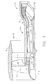
- FIG. 1 is a cross-sectional view of a portion of an exemplary gas turbine engine 10 that includes a forward fan assembly 12 and an aft fan assembly 14 disposed about a longitudinal centerline axis 16.
- the terms "forward fan” and “aft fan” are used herein to indicate that one of the fans 12 is coupled axially upstream from the other fan 14.
- fan assemblies 12 and 14 are positioned at a forward end of gas turbine engine 10 as illustrated.
- fan assemblies 12 and 14 are positioned at an aft end of gas turbine engine 10.
- Fan assemblies 12 and 14 each include a plurality of rows of rotor blades 19 positioned within a nacelle 18. Blades 19 are joined to respective rotor disks 21 that are rotatably coupled through a respective fan shaft 20 to forward fan assembly 12 and through a fan shaft 22 to aft fan assembly 14.
- Gas turbine engine 10 also includes a core engine 24 that is downstream from fan assemblies 12 and 14.
- Core engine 24 includes a high-pressure compressor (HPC) 26, a combustor 28, and a high-pressure turbine (HPT) 30 that is coupled to HPC 26 via a core rotor or shaft 32.
- HPC high-pressure compressor
- HPT high-pressure turbine
- core engine 24 generates combustion gases that are channeled downstream to a counter-rotating low-pressure turbine 34 which extracts energy from the gases for powering fan assemblies 12 and 14 through their respective fan shafts 20 and 22.
- FIG 2 is a schematic diagram of an exemplary gas turbine engine 100 that includes a gearbox assembly 102 and a counter-rotating low-pressure turbine 104.
- Turbine 104 includes a first turbine rotor 106 and a second turbine rotor 108.
- gas turbine engine 100 is substantially similar to gas turbine engine 10 (shown in Figure 1), and components of gas turbine engine 100 that are identical to components of gas turbine engine 10 are identified in Figure 2 using the same reference numerals used in Figure 1.
- Gas turbine engine 100 includes forward fan assembly 12 and aft fan assembly 14 disposed about longitudinal centerline axis 16. Fan assemblies 12 and 14 each include plurality of rows of rotor blades 19 positioned within nacelle 18. Blades 19 are coupled to respective rotor disks 21. Gas turbine engine 100 also includes core engine 24 that is downstream from fan assemblies 12 and 14. Core engine 24 includes high-pressure compressor (HPC) 26, combustor 28, and high-pressure turbine (HPT) 30 that is coupled to HPC 26 via core rotor or shaft 32 (shown in Figure 1).
- HPC high-pressure compressor
- HPT high-pressure turbine
- gas turbine engine 100 includes first shaft 110 that rotatably couples aft fan 14 to gearbox assembly 102, a second shaft 112 that rotatably couples gearbox assembly 102 to first turbine rotor 106, and third shaft 20 that rotatably couples forward fan 12 to a second turbine rotor 108.
- gearbox assembly 102 includes a forward end 120 that is coupled to aft fan assembly 14 using shaft 110, and an aft end 122 that is coupled to first turbine rotor 106 using shaft 112.
- gearbox assembly 102 has a gear ratio of between approximately 2.5 to 1 and approximately 4.5 to 1.
- gearbox assembly 102 has a gear ratio of approximately 3.5 to 1 such that first turbine rotor 106 rotates at a rotational speed that is approximately 3.5 times the rotational speed of aft fan 14.
- forward fan assembly 12 rotates at a rotational speed that is between approximately .9 and 2.1 times the rotational speed of aft fan assembly 14 in the opposite rotational direction.
- forward fan assembly 12 rotates at a rotational speed that is approximately 1.5 times the rotational speed of aft fan assembly 14 in the opposite rotational direction.
- forward fan assembly 12 rotates at a rotational speed that is greater than the rotational speed of aft fan assembly 14, and in an alternative embodiment, forward fan assembly 12 rotates at a rotational speed that is less than the rotational speed of aft fan assembly 14.
- Gas turbine engine 100 also includes a booster compressor 124 that is coupled to shaft 112.
- booster compressor 124 includes at least one row of rotor blades 125 that are coupled to a respective rotor disk 126.
- booster compressor 124 is positioned axially aft of an inlet guide vane 127 and rotates at a rotational speed that is substantially equal to a rotational speed of first turbine rotor 106.
- booster compressor 124 is shown having a single row of rotor blades 125, it should be realized that booster compressor 124 may have a plurality of rows of rotor blades 125 that are interdigitated with a plurality of inlet guide vanes 127.
- inlet guide vanes 127 are fixedly coupled to a booster case 129.
- rotor blades 125 are rotatably coupled to rotor disk 126 such that inlet guide vanes 127 are movable during engine operation to facilitate varying a quantity of air channeled through booster compressor 124.
- low-pressure turbine first rotor 106 is positioned axially forward of low-pressure turbine rotor 108.
- Turbine rotor 106 includes a plurality of circumferentially-spaced rotor blades 130 that extend radially outwardly. Blades 130 are arranged in axially-spaced rows of turbine blades 132.
- first turbine rotor 106 may have any quantity of rows of turbine blades 132 without affecting the scope of the method and apparatus described herein.
- first turbine rotor 106 includes a first row 134 that is positioned axially aft of a first vane 136 and axially forward of a second vane 138, and a second row 140 that is positioned axially aft of second vane 138. More specifically, first turbine rotor 106 includes a plurality of rows of turbine blades 132 that are interdigitated with a plurality of vanes 136 and 138, for example. In the exemplary embodiment, first turbine rotor 106 rotates in a first rotational direction. During operation, combustion air is channeled from high-pressure turbine 30 through vane 136, first row 134, second vane 138, and through second row 140. The combustion air that is discharged from second row 140 is then channeled to second turbine rotor 108.
- second turbine rotor 108 is positioned axially aft of first turbine rotor 106 and configured to rotate in a second rotational direction that is opposite the first rotational direction of first turbine rotor 106.
- Second turbine rotor 108 includes a plurality of circumferentially-spaced rotor blades 150 that extend radially outwardly. Blades 150 are arranged in axially-spaced rows of turbine blades 152.
- the exemplary embodiment illustrates only four rows of turbine blades 152, it should be realized that second turbine rotor 108 may have any quantity of rows of turbine blades 152 without affecting the scope of the method and apparatus described herein.
- plurality of rows of turbine blades 152 are interdigitated with a plurality of vanes 154.
- second turbine rotor 108 includes a first row of turbine blades 160 that is positioned axially aft of turbine blade row 140 and axially forward of a vane 162, and a second row of turbine blades 164 that is positioned axially aft of a second vane 166 such that plurality of rows of turbine blades 152 straddle plurality of vanes 154.
- At least one row of turbine blades 152 is positioned axially forward of a plurality of vanes 154, and at least one row of turbine blades 152 is positioned axially aft of plurality of vanes 154 such that rotor 108 straddles plurality of vanes 154.
- forward fan assembly 12 is operably coupled to second turbine rotor 108
- aft fan assembly is operably coupled to first turbine rotor 106 through gearbox assembly 102 such that aft fan assembly 14 operates at a lower rotational speed than forward fan assembly 12 to facilitate increasing total fan pressure ratios.
- coupling fan assembly 14 to gearbox assembly 102 to a lower a rotational speed of fan assembly 14 facilitates reducing a diameter of fan assemblies 12 and 14 compared to known gas turbine engines fan assemblies while also significantly reducing engine noise.
- aft fan assembly 14 is matched with high performance booster 124 and first turbine rotor 106 using gearbox assembly 102.
- Gearbox assembly 102 has a gear ratio of between approximately 2.5 to 1 and approximately 4.5 to 1 to facilitate enabling relatively small, high speed, one or two stage boosters 124, and/or a low-pressure turbine that includes one or two low-pressure turbine stages 134 to be utilized within gas turbine engine 10.
- booster assembly 124 is coupled between aft fan assembly 14 and core engine 24 such that booster assembly 124 is not nested, i.e. interdigitatedly driven by both fans as accomplished in known gas turbine engines.
- gearbox assembly 102 drives only aft fan assembly 14
- gearbox horsepower required to drive aft fan assembly is also reduced, thus a size of gearbox assembly 102 can be reduced.
- quantity of rows of turbine blades required to drive aft fan assembly 14 can be reduced by several stages compared to known gas turbine engines.
- FIG 3 is a schematic diagram of a straddle-mounted counter-rotating low-pressure turbine assembly 200 that may be used with a gas turbine engine similar to gas turbine engine 100 (shown in Figure 2).
- low-pressure turbine 200 includes a stationary outer casing 36 that is coupled to core engine 24 (shown in Figure 2) downstream from high-pressure turbine 30 (shown in Figure 2).
- Low-pressure turbine 200 includes a first rotor 210 that has a generally frusto-conical shape and includes a plurality of circumferentially-spaced rotor blades 212 that extend radially outwardly. Blades 212 are arranged in axially-spaced rows of blades 214. Although, the exemplary embodiment illustrates only two rows of blades 214, it should be realized that first rotor 210 may have any quantity of rows of blades 214 without affecting the scope of the method and apparatus described herein. More specifically, first rotor 210, in the exemplary embodiment, includes M rows of turbine blades 214 and is rotatably coupled to gearbox assembly 102 (shown in Figure 2) via shaft 112.
- Low-pressure turbine 200 also includes a second rotor 220 that includes a plurality of circumferentially-spaced rotor blades 222 that extend radially outwardly. Blades 222 are arranged in axially-spaced rows of blades 224. Although, the exemplary embodiment illustrates only four rows of blades 224, it should be realized that second rotor 220 may have any quantity of rows of blades 224 without affecting the scope of the method and apparatus described herein. More specifically, in the exemplary embodiment, second rotor 220 includes N rows of turbine blades 224, wherein N is greater than M. Second rotor 220 is rotatably coupled to forward fan assembly 12 (shown in Figure 2) via shaft 20.
- At least one of the plurality of rows of turbine blades 224 is coupled axially forward of at least one of the plurality of rows of turbine blades 214.
- second rotor 220 includes a first row of turbine blades 230 that is coupled to a second row of turbine blades 232 utilizing a connecting member 234.
- at least one row of turbine blades 230 is positioned between two adjacent rows of turbine blades 214 such that at least a portion of second rotor 220 is interdigitated with at least a portion of first rotor 210.
- forward fan assembly 12 is rotatably coupled to second turbine rotor 108, and aft fan assembly is rotatably coupled to first turbine rotor 106 through gearbox assembly 102 such that aft fan assembly 14 operates with a lower rotational speed than forward fan assembly 12.
- the lower rotational speed of aft fan assembly 14 facilitates increasing total fan pressure ratios while utilizing fan assemblies 12 and 14 that have smaller fan diameters than known gas turbine engines fan assemblies.
- the combination of the reduced rotational speed and the small diameters of fan assemblies 12 and 14 facilitates significantly reducing engine noise in comparison to known gas turbine engines.
- the overall size of low-pressure turbine 200 can be reduced by several stages and is not nested compared to known low pressure turbines.
- aft fan assembly 14 is coupled to gearbox assembly 102 to facilitate utilizing a tandem low-pressure turbine that is lighter in weight compared to a known five stage nested counter-rotating low pressure turbine.
- gas turbine engines 100 and 200 each include a booster compressor that facilitates speed match control at all power settings.
- the gas turbine engines described herein include a counter-rotating low-pressure turbine that includes a smaller diameter to facilitate reducing the weight of the gas turbine engine. Since the low-pressure turbines described herein have a smaller diameter, the turbine mid-frame can be shortened. Moreover, the low-pressure turbines described herein do not require a rotating frame structure or disks in the outer flowpath. Additionally, seals currently required in at least some known low-pressure turbine outer cases can be eliminated as the quantity of air required to cool the low-pressure turbine structure can be reduced.
Abstract
Description
- This invention relates generally to aircraft gas turbine engines, and more specifically to counter-rotating gas turbine engines.
- At least some known gas turbine engines include a forward fan, a core engine, and a power turbine. The core engine includes at least one compressor, a combustor, a high-pressure turbine, and a low-pressure turbine coupled together in a serial flow relationship. More specifically, the compressor and high-pressure turbine are coupled through a high-pressure shaft to define a high-pressure rotor. The compressor compresses air entering the core engine that is then mixed with fuel and ignited to form a high energy gas stream. The gas stream flows through the high-pressure turbine, rotatably driving it and the high-pressure shaft that, in turn, rotatably drives the compressor.
- The gas stream is expanded as it flows through the low-pressure turbine. The low-pressure turbine rotatably drives the fan through a low-pressure shaft such that a low-pressure rotor is defined by the fan, the low-pressure shaft, and the low-pressure turbine. At least some known low pressure turbines include counter-rotating turbines that power counter-rotating fans and counter-rotating boosters and/or low pressure compressors.
- When operating such counter-rotating turbines, torque is split substantially equally between the forward and aft fan shafts to facilitate optimizing the efficiency of such turbines. Moreover, engine performance may be improved, for example, by operating the forward fan at a higher fan pressure ratio and/or higher rotational speed than the aft fan. However, operating the aft fan at a lower fan speed and/or a lower fan pressure ratio may cause booster stages that are driven off the aft fan to operate below a peak efficiency and/or reduce the performance of the low-pressure turbine driving the aft fan.
- In one aspect of the invention, a method for assembling a gas turbine engine is provided. The method includes providing a first fan assembly including a plurality of rotor blades that are configured to rotate in a first rotational direction at a first rotational speed, rotatably coupling a second fan assembly axially aft of the first fan assembly, wherein the second fan assembly includes a plurality of rotor blades that are configured to rotate in a second rotational direction, and coupling a gearbox to the second fan assembly that is configured to rotate the second fan assembly at a second rotational speed that is different than the first rotational speed.
- In another aspect of the invention, a fan assembly is provided. The fan assembly includes a first fan assembly comprising a plurality of rotor blades configured to rotate in a first rotational direction and at a first rotational speed, a second fan assembly including a plurality of rotor blades configured to rotate in a second rotational direction, wherein the second fan assembly is coupled axially aft of the first fan assembly, and a gearbox coupled to the second fan assembly, the gearbox is configured to rotate the second fan assembly at a second rotational speed that is different than the first rotational speed.
- In a further aspect of the invention, a gas turbine engine is provided. The gas turbine engine includes a first fan assembly comprising a plurality of rotor blades configured to rotate in a first rotational direction and at a first rotational speed, a second fan assembly including a plurality of rotor blades configured to rotate in a second rotational direction, wherein the second fan assembly is coupled axially aft of the first fan assembly, and a gearbox coupled to the second fan assembly, the gearbox is configured to rotate the second fan assembly at a second rotational speed that is different than the first rotational speed.
- The invention will now be described in greater detail, by way of example, with reference to the drawings, in which:-
- Figure 1 is a cross-sectional view of a portion of an exemplary gas turbine engine;
- Figure 2 is a schematic diagram of an exemplary gas turbine engine that includes a gear assembly; and
- Figure 3 is a schematic diagram of an exemplary counter-rotating low-pressure turbine that can be used with the gas turbine engine shown in Figure 2.
- Figure 1 is a cross-sectional view of a portion of an exemplary
gas turbine engine 10 that includes aforward fan assembly 12 and anaft fan assembly 14 disposed about alongitudinal centerline axis 16. The terms "forward fan" and "aft fan" are used herein to indicate that one of thefans 12 is coupled axially upstream from theother fan 14. In one embodiment,fan assemblies gas turbine engine 10 as illustrated. In an alternative embodiment,fan assemblies gas turbine engine 10.Fan assemblies rotor blades 19 positioned within anacelle 18.Blades 19 are joined torespective rotor disks 21 that are rotatably coupled through arespective fan shaft 20 toforward fan assembly 12 and through afan shaft 22 toaft fan assembly 14. -
Gas turbine engine 10 also includes acore engine 24 that is downstream fromfan assemblies Core engine 24 includes a high-pressure compressor (HPC) 26, acombustor 28, and a high-pressure turbine (HPT) 30 that is coupled to HPC 26 via a core rotor orshaft 32. In operation,core engine 24 generates combustion gases that are channeled downstream to a counter-rotating low-pressure turbine 34 which extracts energy from the gases for powering fan assemblies 12 and 14 through theirrespective fan shafts - Figure 2 is a schematic diagram of an exemplary
gas turbine engine 100 that includes agearbox assembly 102 and a counter-rotating low-pressure turbine 104. Turbine 104 includes afirst turbine rotor 106 and asecond turbine rotor 108. In the exemplary embodiment,gas turbine engine 100 is substantially similar to gas turbine engine 10 (shown in Figure 1), and components ofgas turbine engine 100 that are identical to components ofgas turbine engine 10 are identified in Figure 2 using the same reference numerals used in Figure 1. -
Gas turbine engine 100 includesforward fan assembly 12 andaft fan assembly 14 disposed aboutlongitudinal centerline axis 16. Fan assemblies 12 and 14 each include plurality of rows ofrotor blades 19 positioned withinnacelle 18.Blades 19 are coupled torespective rotor disks 21.Gas turbine engine 100 also includescore engine 24 that is downstream fromfan assemblies Core engine 24 includes high-pressure compressor (HPC) 26,combustor 28, and high-pressure turbine (HPT) 30 that is coupled to HPC 26 via core rotor or shaft 32 (shown in Figure 1). - In the exemplary embodiment,
gas turbine engine 100 includesfirst shaft 110 that rotatablycouples aft fan 14 togearbox assembly 102, asecond shaft 112 that rotatablycouples gearbox assembly 102 tofirst turbine rotor 106, andthird shaft 20 that rotatably couplesforward fan 12 to asecond turbine rotor 108. More specifically,gearbox assembly 102 includes aforward end 120 that is coupled toaft fan assembly 14 usingshaft 110, and anaft end 122 that is coupled tofirst turbine rotor 106 usingshaft 112. In one embodiment,gearbox assembly 102 has a gear ratio of between approximately 2.5 to 1 and approximately 4.5 to 1. In the exemplary embodiment,gearbox assembly 102 has a gear ratio of approximately 3.5 to 1 such thatfirst turbine rotor 106 rotates at a rotational speed that is approximately 3.5 times the rotational speed ofaft fan 14. In one embodiment,forward fan assembly 12 rotates at a rotational speed that is between approximately .9 and 2.1 times the rotational speed ofaft fan assembly 14 in the opposite rotational direction. In the exemplary embodiment,forward fan assembly 12 rotates at a rotational speed that is approximately 1.5 times the rotational speed ofaft fan assembly 14 in the opposite rotational direction. Accordingly, in one embodiment,forward fan assembly 12 rotates at a rotational speed that is greater than the rotational speed ofaft fan assembly 14, and in an alternative embodiment,forward fan assembly 12 rotates at a rotational speed that is less than the rotational speed ofaft fan assembly 14. -
Gas turbine engine 100 also includes abooster compressor 124 that is coupled toshaft 112. In the exemplary embodiment,booster compressor 124 includes at least one row of rotor blades 125 that are coupled to arespective rotor disk 126. In the exemplary embodiment,booster compressor 124 is positioned axially aft of aninlet guide vane 127 and rotates at a rotational speed that is substantially equal to a rotational speed offirst turbine rotor 106. Althoughbooster compressor 124 is shown having a single row of rotor blades 125, it should be realized thatbooster compressor 124 may have a plurality of rows of rotor blades 125 that are interdigitated with a plurality ofinlet guide vanes 127. In one embodiment,inlet guide vanes 127 are fixedly coupled to a booster case 129. In another embodiment, rotor blades 125 are rotatably coupled torotor disk 126 such thatinlet guide vanes 127 are movable during engine operation to facilitate varying a quantity of air channeled throughbooster compressor 124. - In the exemplary embodiment, low-pressure turbine
first rotor 106 is positioned axially forward of low-pressure turbine rotor 108.Turbine rotor 106 includes a plurality of circumferentially-spacedrotor blades 130 that extend radially outwardly.Blades 130 are arranged in axially-spaced rows ofturbine blades 132. Although, the exemplary embodiment illustrates only two rows ofturbine blades 132, it should be realized thatfirst turbine rotor 106 may have any quantity of rows ofturbine blades 132 without affecting the scope of the method and apparatus described herein. More specifically,first turbine rotor 106 includes afirst row 134 that is positioned axially aft of afirst vane 136 and axially forward of asecond vane 138, and asecond row 140 that is positioned axially aft ofsecond vane 138. More specifically,first turbine rotor 106 includes a plurality of rows ofturbine blades 132 that are interdigitated with a plurality ofvanes first turbine rotor 106 rotates in a first rotational direction. During operation, combustion air is channeled from high-pressure turbine 30 throughvane 136,first row 134,second vane 138, and throughsecond row 140. The combustion air that is discharged fromsecond row 140 is then channeled tosecond turbine rotor 108. - In the exemplary embodiment,
second turbine rotor 108 is positioned axially aft offirst turbine rotor 106 and configured to rotate in a second rotational direction that is opposite the first rotational direction offirst turbine rotor 106.Second turbine rotor 108 includes a plurality of circumferentially-spacedrotor blades 150 that extend radially outwardly.Blades 150 are arranged in axially-spaced rows ofturbine blades 152. Although, the exemplary embodiment illustrates only four rows ofturbine blades 152, it should be realized thatsecond turbine rotor 108 may have any quantity of rows ofturbine blades 152 without affecting the scope of the method and apparatus described herein. In the exemplary embodiment, plurality of rows ofturbine blades 152 are interdigitated with a plurality ofvanes 154. More specifically,second turbine rotor 108 includes a first row ofturbine blades 160 that is positioned axially aft ofturbine blade row 140 and axially forward of avane 162, and a second row ofturbine blades 164 that is positioned axially aft of asecond vane 166 such that plurality of rows ofturbine blades 152 straddle plurality ofvanes 154. In the exemplary embodiment, at least one row ofturbine blades 152 is positioned axially forward of a plurality ofvanes 154, and at least one row ofturbine blades 152 is positioned axially aft of plurality ofvanes 154 such thatrotor 108 straddles plurality ofvanes 154. - During operation,
forward fan assembly 12 is operably coupled tosecond turbine rotor 108, and aft fan assembly is operably coupled tofirst turbine rotor 106 throughgearbox assembly 102 such thataft fan assembly 14 operates at a lower rotational speed thanforward fan assembly 12 to facilitate increasing total fan pressure ratios. Moreover, couplingfan assembly 14 togearbox assembly 102 to a lower a rotational speed offan assembly 14 facilitates reducing a diameter offan assemblies - More specifically, during assembly,
aft fan assembly 14 is matched withhigh performance booster 124 andfirst turbine rotor 106 usinggearbox assembly 102.Gearbox assembly 102 has a gear ratio of between approximately 2.5 to 1 and approximately 4.5 to 1 to facilitate enabling relatively small, high speed, one or twostage boosters 124, and/or a low-pressure turbine that includes one or two low-pressure turbine stages 134 to be utilized withingas turbine engine 10. Moreover,booster assembly 124 is coupled betweenaft fan assembly 14 andcore engine 24 such thatbooster assembly 124 is not nested, i.e. interdigitatedly driven by both fans as accomplished in known gas turbine engines. Sincegearbox assembly 102 drives onlyaft fan assembly 14, the gearbox horsepower required to drive aft fan assembly is also reduced, thus a size ofgearbox assembly 102 can be reduced. Moreover, the quantity of rows of turbine blades required to driveaft fan assembly 14 can be reduced by several stages compared to known gas turbine engines. - Figure 3 is a schematic diagram of a straddle-mounted counter-rotating low-
pressure turbine assembly 200 that may be used with a gas turbine engine similar to gas turbine engine 100 (shown in Figure 2). In the exemplary embodiment, low-pressure turbine 200 includes a stationaryouter casing 36 that is coupled to core engine 24 (shown in Figure 2) downstream from high-pressure turbine 30 (shown in Figure 2). - Low-
pressure turbine 200 includes afirst rotor 210 that has a generally frusto-conical shape and includes a plurality of circumferentially-spacedrotor blades 212 that extend radially outwardly.Blades 212 are arranged in axially-spaced rows ofblades 214. Although, the exemplary embodiment illustrates only two rows ofblades 214, it should be realized thatfirst rotor 210 may have any quantity of rows ofblades 214 without affecting the scope of the method and apparatus described herein. More specifically,first rotor 210, in the exemplary embodiment, includes M rows ofturbine blades 214 and is rotatably coupled to gearbox assembly 102 (shown in Figure 2) viashaft 112. - Low-
pressure turbine 200 also includes asecond rotor 220 that includes a plurality of circumferentially-spacedrotor blades 222 that extend radially outwardly.Blades 222 are arranged in axially-spaced rows ofblades 224. Although, the exemplary embodiment illustrates only four rows ofblades 224, it should be realized thatsecond rotor 220 may have any quantity of rows ofblades 224 without affecting the scope of the method and apparatus described herein. More specifically, in the exemplary embodiment,second rotor 220 includes N rows ofturbine blades 224, wherein N is greater thanM. Second rotor 220 is rotatably coupled to forward fan assembly 12 (shown in Figure 2) viashaft 20. - In the exemplary embodiment, at least one of the plurality of rows of
turbine blades 224 is coupled axially forward of at least one of the plurality of rows ofturbine blades 214. More specifically,second rotor 220 includes a first row ofturbine blades 230 that is coupled to a second row of turbine blades 232 utilizing a connecting member 234. In the exemplary embodiment, at least one row ofturbine blades 230 is positioned between two adjacent rows ofturbine blades 214 such that at least a portion ofsecond rotor 220 is interdigitated with at least a portion offirst rotor 210. - During operation,
forward fan assembly 12 is rotatably coupled tosecond turbine rotor 108, and aft fan assembly is rotatably coupled tofirst turbine rotor 106 throughgearbox assembly 102 such thataft fan assembly 14 operates with a lower rotational speed thanforward fan assembly 12. The lower rotational speed ofaft fan assembly 14 facilitates increasing total fan pressure ratios while utilizingfan assemblies fan assemblies pressure turbine 200 can be reduced by several stages and is not nested compared to known low pressure turbines. Moreover,aft fan assembly 14 is coupled togearbox assembly 102 to facilitate utilizing a tandem low-pressure turbine that is lighter in weight compared to a known five stage nested counter-rotating low pressure turbine. Additionally,gas turbine engines - The gas turbine engines described herein include a counter-rotating low-pressure turbine that includes a smaller diameter to facilitate reducing the weight of the gas turbine engine. Since the low-pressure turbines described herein have a smaller diameter, the turbine mid-frame can be shortened. Moreover, the low-pressure turbines described herein do not require a rotating frame structure or disks in the outer flowpath. Additionally, seals currently required in at least some known low-pressure turbine outer cases can be eliminated as the quantity of air required to cool the low-pressure turbine structure can be reduced.
Claims (10)
- A fan assembly comprising:a first fan assembly (12) comprising a plurality of rotor blades (19) configured to rotate in a first rotational direction and at a first rotational speed;a second fan assembly (14) comprising a plurality of rotor blades configured to rotate in a second rotational direction, wherein said second fan assembly is coupled axially aft of said first fan assembly; anda gearbox (102) coupled to said second fan assembly, said gearbox configured to rotate said second fan assembly at a second rotational speed that is different than the first rotational speed.
- A fan assembly in accordance with Claim 1 wherein said gearbox (102) has a gear ratio that is approximately equal to 3.5 to 1.
- A fan assembly in accordance with Claim 1 wherein said second fan assembly (14) is coupled axially aft of said first fan assembly (12).
- A fan assembly in accordance with Claim 1 wherein said second rotational speed is less than said first rotational speed.
- A fan assembly in accordance with Claim 1 wherein said first fan assembly (12) is coupled to a first turbine rotor (108), said second fan assembly (14) is coupled to a second turbine rotor (106) that is positioned axially forward of said first turbine rotor such that said gearbox (102) is coupled between said second fan assembly and said second turbine rotor.
- A fan assembly in accordance with Claim 5 wherein said first turbine rotor (108) comprises a first plurality of rows (152) of turbine blades (150), said second turbine rotor (106) comprises a second plurality of rows (132) of turbine blades (130) that is different than the first plurality of rows of turbine blades.
- A gas turbine engine (10) comprising:a first fan assembly (12) comprising a plurality of rotor blades (19)configured to rotate in a first rotational direction and at a first rotational speed;a second fan assembly (14) comprising a plurality of rotor blades configured to rotate in a second rotational direction, wherein said second fan assembly is coupled axially aft of said first fan assembly; anda gearbox (102) coupled to said second fan assembly, said gearbox configured to rotate said second fan at a second rotational speed that is different than the first rotational speed.
- A gas turbine engine (10) in accordance with Claim 7 wherein said gearbox (102) has a gear ratio that is approximately equal to 3.5 to 1 such that the second rotational speed is less than the first rotational speed.
- A gas turbine engine (10) in accordance with Claim 7 further comprising:a first low-pressure turbine rotor (108) that is coupled to said first fan assembly (12); anda second low-pressure turbine rotor (106) that is coupled to said gearbox (102), at least a portion of said second turbine rotor is positioned upstream from at least a portion of said first turbine rotor.
- A gas turbine engine (10) in accordance with Claim 9 further comprising:a shaft (112) coupled between said second fan assembly (14) and said second turbine rotor (106), anda booster compressor (124) coupled to said shaft, said booster compressor coupled between said second fan assembly and said second turbine rotor.
Applications Claiming Priority (1)
| Application Number | Priority Date | Filing Date | Title |
|---|---|---|---|
| US10/977,075 US7334392B2 (en) | 2004-10-29 | 2004-10-29 | Counter-rotating gas turbine engine and method of assembling same |
Publications (3)
| Publication Number | Publication Date |
|---|---|
| EP1653064A2 true EP1653064A2 (en) | 2006-05-03 |
| EP1653064A3 EP1653064A3 (en) | 2011-05-04 |
| EP1653064B1 EP1653064B1 (en) | 2013-12-11 |
Family
ID=35448079
Family Applications (1)
| Application Number | Title | Priority Date | Filing Date |
|---|---|---|---|
| EP05256559.5A Expired - Fee Related EP1653064B1 (en) | 2004-10-29 | 2005-10-21 | Gas turbine engine with counter rotating blades |
Country Status (3)
| Country | Link |
|---|---|
| US (1) | US7334392B2 (en) |
| EP (1) | EP1653064B1 (en) |
| JP (1) | JP4906311B2 (en) |
Cited By (11)
| Publication number | Priority date | Publication date | Assignee | Title |
|---|---|---|---|---|
| GB2443534A (en) * | 2006-10-31 | 2008-05-07 | Gen Electric | Turbofan engine |
| EP2009270A2 (en) * | 2007-06-28 | 2008-12-31 | United Technologies Corporation | Gas turbine with multiple gas flow paths |
| WO2010059321A3 (en) * | 2008-11-21 | 2011-04-14 | General Electric Company | Gas turbine engine booster having rotatable radially inwardly extending blades and non-rotatable vanes |
| US7926259B2 (en) | 2006-10-31 | 2011-04-19 | General Electric Company | Turbofan engine assembly and method of assembling same |
| EP2270315A3 (en) * | 2009-06-30 | 2011-06-01 | General Electric Company | Aircraft gas turbine engine counter-rotatable generator |
| US8063528B2 (en) | 2009-12-18 | 2011-11-22 | General Electric Company | Counter-rotatable generator |
| EP2776318A1 (en) * | 2011-12-30 | 2014-09-17 | United Technologies Corporation | Gas turbine engine with low stage count low pressure turbine |
| EP2884056A1 (en) * | 2013-12-11 | 2015-06-17 | United Technologies Corporation | Systems and methods involving multiple torque paths for gas turbine engines |
| EP2820250A4 (en) * | 2012-02-28 | 2015-12-09 | United Technologies Corp | Gas turbine engine with fan-tied inducer section |
| US9359960B2 (en) | 2007-06-28 | 2016-06-07 | United Technologies Corporation | Gas turbines with multiple gas flow paths |
| US9850821B2 (en) | 2012-02-28 | 2017-12-26 | United Technologies Corporation | Gas turbine engine with fan-tied inducer section |
Families Citing this family (85)
| Publication number | Priority date | Publication date | Assignee | Title |
|---|---|---|---|---|
| ZA200609927B (en) | 2004-05-28 | 2008-07-30 | Unigen Pharmaceuticals Inc | Diarylalkanes as potent inhibitors of binuclear enzymes |
| DE102004042739A1 (en) * | 2004-09-03 | 2006-03-09 | Mtu Aero Engines Gmbh | Fan for an aircraft engine and aircraft engine |
| US7513103B2 (en) * | 2005-10-19 | 2009-04-07 | General Electric Company | Gas turbine engine assembly and methods of assembling same |
| US7526913B2 (en) * | 2005-10-19 | 2009-05-05 | General Electric Company | Gas turbine engine assembly and methods of assembling same |
| US7685808B2 (en) * | 2005-10-19 | 2010-03-30 | General Electric Company | Gas turbine engine assembly and methods of assembling same |
| US7726113B2 (en) * | 2005-10-19 | 2010-06-01 | General Electric Company | Gas turbine engine assembly and methods of assembling same |
| US7490461B2 (en) * | 2005-10-19 | 2009-02-17 | General Electric Company | Gas turbine engine assembly and methods of assembling same |
| US7493753B2 (en) * | 2005-10-19 | 2009-02-24 | General Electric Company | Gas turbine engine assembly and methods of assembling same |
| US7694505B2 (en) * | 2006-07-31 | 2010-04-13 | General Electric Company | Gas turbine engine assembly and method of assembling same |
| WO2008105815A2 (en) * | 2006-08-22 | 2008-09-04 | Rolls-Royce North American Technologies, Inc. | Gas turbine engine with intermediate speed booster |
| US20110049894A1 (en) * | 2006-10-06 | 2011-03-03 | Green William M | Electricity Generating Assembly |
| US7966806B2 (en) * | 2006-10-31 | 2011-06-28 | General Electric Company | Turbofan engine assembly and method of assembling same |
| US7921634B2 (en) * | 2006-10-31 | 2011-04-12 | General Electric Company | Turbofan engine assembly and method of assembling same |
| US7841165B2 (en) * | 2006-10-31 | 2010-11-30 | General Electric Company | Gas turbine engine assembly and methods of assembling same |
| US8104289B2 (en) * | 2007-10-09 | 2012-01-31 | United Technologies Corp. | Systems and methods involving multiple torque paths for gas turbine engines |
| US8015798B2 (en) * | 2007-12-13 | 2011-09-13 | United Technologies Corporation | Geared counter-rotating gas turbofan engine |
| US8181442B2 (en) * | 2008-05-05 | 2012-05-22 | Pratt & Whitney Canada Corp. | Gas turbine aircraft engine with power variability |
| EP2123884B1 (en) * | 2008-05-13 | 2015-03-04 | Rolls-Royce Corporation | Dual clutch arrangement |
| US8807477B2 (en) | 2008-06-02 | 2014-08-19 | United Technologies Corporation | Gas turbine engine compressor arrangement |
| US8800914B2 (en) | 2008-06-02 | 2014-08-12 | United Technologies Corporation | Gas turbine engine with low stage count low pressure turbine |
| US8128021B2 (en) | 2008-06-02 | 2012-03-06 | United Technologies Corporation | Engine mount system for a turbofan gas turbine engine |
| US20140174056A1 (en) | 2008-06-02 | 2014-06-26 | United Technologies Corporation | Gas turbine engine with low stage count low pressure turbine |
| US9097137B2 (en) * | 2008-06-12 | 2015-08-04 | United Technologies Corporation | Integrated actuator module for gas turbine engine |
| US20100005810A1 (en) * | 2008-07-11 | 2010-01-14 | Rob Jarrell | Power transmission among shafts in a turbine engine |
| KR102527742B1 (en) | 2008-07-21 | 2023-04-28 | 유니젠, 인크. | Series of skin-whitening (lightening) compounds |
| US8480527B2 (en) * | 2008-08-27 | 2013-07-09 | Rolls-Royce Corporation | Gearing arrangement |
| US8834315B2 (en) * | 2008-10-12 | 2014-09-16 | Christopher C. Sappenfield | Rotary units, rotary mechanisms, and related applications |
| US8075438B2 (en) * | 2008-12-11 | 2011-12-13 | Rolls-Royce Corporation | Apparatus and method for transmitting a rotary input into counter-rotating outputs |
| US8021267B2 (en) * | 2008-12-11 | 2011-09-20 | Rolls-Royce Corporation | Coupling assembly |
| US8191352B2 (en) * | 2008-12-19 | 2012-06-05 | General Electric Company | Geared differential speed counter-rotatable low pressure turbine |
| US8162615B2 (en) * | 2009-03-17 | 2012-04-24 | United Technologies Corporation | Split disk assembly for a gas turbine engine |
| US8371127B2 (en) * | 2009-10-01 | 2013-02-12 | Pratt & Whitney Canada Corp. | Cooling air system for mid turbine frame |
| US8586799B2 (en) | 2011-03-24 | 2013-11-19 | Unigen, Inc. | Compounds and methods for preparation of diarylpropanes |
| US8777793B2 (en) | 2011-04-27 | 2014-07-15 | United Technologies Corporation | Fan drive planetary gear system integrated carrier and torque frame |
| US9631558B2 (en) | 2012-01-03 | 2017-04-25 | United Technologies Corporation | Geared architecture for high speed and small volume fan drive turbine |
| US9239012B2 (en) | 2011-06-08 | 2016-01-19 | United Technologies Corporation | Flexible support structure for a geared architecture gas turbine engine |
| US9279341B2 (en) | 2011-09-22 | 2016-03-08 | Pratt & Whitney Canada Corp. | Air system architecture for a mid-turbine frame module |
| US9038366B2 (en) | 2012-01-31 | 2015-05-26 | United Technologies Corporation | LPC flowpath shape with gas turbine engine shaft bearing configuration |
| US8863491B2 (en) | 2012-01-31 | 2014-10-21 | United Technologies Corporation | Gas turbine engine shaft bearing configuration |
| US10400629B2 (en) | 2012-01-31 | 2019-09-03 | United Technologies Corporation | Gas turbine engine shaft bearing configuration |
| US20130192240A1 (en) * | 2012-01-31 | 2013-08-01 | Peter M. Munsell | Buffer system for a gas turbine engine |
| US20130192256A1 (en) | 2012-01-31 | 2013-08-01 | Gabriel L. Suciu | Geared turbofan engine with counter-rotating shafts |
| US20130192198A1 (en) | 2012-01-31 | 2013-08-01 | Lisa I. Brilliant | Compressor flowpath |
| US20130219859A1 (en) * | 2012-02-29 | 2013-08-29 | Gabriel L. Suciu | Counter rotating low pressure compressor and turbine each having a gear system |
| US9011076B2 (en) | 2012-02-29 | 2015-04-21 | United Technologies Corporation | Counter-rotating low pressure turbine with gear system mounted to turbine exhaust case |
| US9028200B2 (en) | 2012-02-29 | 2015-05-12 | United Technologies Corporation | Counter rotating low pressure turbine with splitter gear system |
| US10138809B2 (en) | 2012-04-02 | 2018-11-27 | United Technologies Corporation | Geared turbofan engine with a high ratio of thrust to turbine volume |
| US20130255275A1 (en) * | 2012-04-02 | 2013-10-03 | Frederick M. Schwarz | Geared turbofan engine with power density range |
| US9074485B2 (en) | 2012-04-25 | 2015-07-07 | United Technologies Corporation | Geared turbofan with three turbines all counter-rotating |
| US8756908B2 (en) | 2012-05-31 | 2014-06-24 | United Technologies Corporation | Fundamental gear system architecture |
| US20150308351A1 (en) | 2012-05-31 | 2015-10-29 | United Technologies Corporation | Fundamental gear system architecture |
| US8572943B1 (en) | 2012-05-31 | 2013-11-05 | United Technologies Corporation | Fundamental gear system architecture |
| US9869190B2 (en) | 2014-05-30 | 2018-01-16 | General Electric Company | Variable-pitch rotor with remote counterweights |
| US9410430B2 (en) * | 2014-06-19 | 2016-08-09 | Jay HASKIN | Turbine apparatus with counter-rotating blades |
| US10072510B2 (en) | 2014-11-21 | 2018-09-11 | General Electric Company | Variable pitch fan for gas turbine engine and method of assembling the same |
| US10077660B2 (en) * | 2014-12-03 | 2018-09-18 | General Electric Company | Turbine engine assembly and method of manufacturing |
| US10100653B2 (en) | 2015-10-08 | 2018-10-16 | General Electric Company | Variable pitch fan blade retention system |
| US10273812B2 (en) | 2015-12-18 | 2019-04-30 | Pratt & Whitney Canada Corp. | Turbine rotor coolant supply system |
| US9745860B1 (en) * | 2016-11-02 | 2017-08-29 | Jay HASKIN | Power transmission system for turbine or compressor having counter-rotating blades |
| US10260367B2 (en) | 2016-11-02 | 2019-04-16 | Jay HASKIN | Power transmission system for turbines or compressors having counter-rotating blades |
| US10539020B2 (en) * | 2017-01-23 | 2020-01-21 | General Electric Company | Two spool gas turbine engine with interdigitated turbine section |
| US10655537B2 (en) * | 2017-01-23 | 2020-05-19 | General Electric Company | Interdigitated counter rotating turbine system and method of operation |
| US10544734B2 (en) * | 2017-01-23 | 2020-01-28 | General Electric Company | Three spool gas turbine engine with interdigitated turbine section |
| US10793281B2 (en) | 2017-02-10 | 2020-10-06 | General Electric Company | Propulsion system for an aircraft |
| US11149578B2 (en) | 2017-02-10 | 2021-10-19 | General Electric Company | Propulsion system for an aircraft |
| US10822103B2 (en) | 2017-02-10 | 2020-11-03 | General Electric Company | Propulsor assembly for an aircraft |
| US10669893B2 (en) | 2017-05-25 | 2020-06-02 | General Electric Company | Air bearing and thermal management nozzle arrangement for interdigitated turbine engine |
| US10718265B2 (en) | 2017-05-25 | 2020-07-21 | General Electric Company | Interdigitated turbine engine air bearing and method of operation |
| US10787931B2 (en) | 2017-05-25 | 2020-09-29 | General Electric Company | Method and structure of interdigitated turbine engine thermal management |
| US10605168B2 (en) | 2017-05-25 | 2020-03-31 | General Electric Company | Interdigitated turbine engine air bearing cooling structure and method of thermal management |
| US10508546B2 (en) * | 2017-09-20 | 2019-12-17 | General Electric Company | Turbomachine with alternatingly spaced turbine rotor blades |
| US10914194B2 (en) * | 2017-09-20 | 2021-02-09 | General Electric Company | Turbomachine with alternatingly spaced turbine rotor blades |
| US10823000B2 (en) | 2017-09-20 | 2020-11-03 | General Electric Company | Turbomachine with alternatingly spaced turbine rotor blades |
| US11098592B2 (en) | 2017-09-20 | 2021-08-24 | General Electric Company | Turbomachine with alternatingly spaced turbine rotor blades |
| US10738617B2 (en) | 2017-09-20 | 2020-08-11 | General Electric Company | Turbomachine with alternatingly spaced turbine rotor blades |
| US10823001B2 (en) | 2017-09-20 | 2020-11-03 | General Electric Company | Turbomachine with alternatingly spaced turbine rotor blades |
| US10781717B2 (en) | 2017-09-20 | 2020-09-22 | General Electric Company | Turbomachine with alternatingly spaced turbine rotor blades |
| EP3578763A1 (en) | 2018-06-07 | 2019-12-11 | Haskin, Jay | Power transmission system for turbine, a turbocharger, a compressor, or a pump |
| GB201902980D0 (en) * | 2019-03-06 | 2019-04-17 | Rolls Royce Plc | Shaft apparatus for a gas turbine engine |
| IT201900014724A1 (en) | 2019-08-13 | 2021-02-13 | Ge Avio Srl | Elements for retaining blades for turbomachinery. |
| IT201900014736A1 (en) | 2019-08-13 | 2021-02-13 | Ge Avio Srl | Integral sealing elements for blades held in a rotatable annular outer drum rotor in a turbomachinery. |
| IT201900014739A1 (en) | 2019-08-13 | 2021-02-13 | Ge Avio Srl | Elements for retaining blades for turbomachinery. |
| US11428160B2 (en) | 2020-12-31 | 2022-08-30 | General Electric Company | Gas turbine engine with interdigitated turbine and gear assembly |
| US11674435B2 (en) | 2021-06-29 | 2023-06-13 | General Electric Company | Levered counterweight feathering system |
| US11795964B2 (en) | 2021-07-16 | 2023-10-24 | General Electric Company | Levered counterweight feathering system |
Family Cites Families (19)
| Publication number | Priority date | Publication date | Assignee | Title |
|---|---|---|---|---|
| GB2195712B (en) * | 1986-10-08 | 1990-08-29 | Rolls Royce Plc | A turbofan gas turbine engine |
| DE3738703A1 (en) * | 1987-05-27 | 1988-12-08 | Mtu Muenchen Gmbh | COMBINED, SWITCHABLE JET ENGINE FOR DRIVING PLANES AND SPACES |
| DE3812027A1 (en) * | 1988-04-11 | 1989-10-26 | Mtu Muenchen Gmbh | PROPFAN TURBO ENGINE |
| US5010729A (en) * | 1989-01-03 | 1991-04-30 | General Electric Company | Geared counterrotating turbine/fan propulsion system |
| FR2646473B1 (en) * | 1989-04-26 | 1991-07-05 | Snecma | MOTOR WITH CONTRAROTATIVE TRACTOR BLOWERS |
| DE4122008A1 (en) * | 1991-07-03 | 1993-01-14 | Mtu Muenchen Gmbh | GAUGE ENGINE WITH COUNTER-PRESSURE LOW-PRESSURE COMPRESSOR (BOOSTER) |
| US5307622A (en) * | 1993-08-02 | 1994-05-03 | General Electric Company | Counterrotating turbine support assembly |
| US5806303A (en) | 1996-03-29 | 1998-09-15 | General Electric Company | Turbofan engine with a core driven supercharged bypass duct and fixed geometry nozzle |
| US5809772A (en) | 1996-03-29 | 1998-09-22 | General Electric Company | Turbofan engine with a core driven supercharged bypass duct |
| US5867980A (en) | 1996-12-17 | 1999-02-09 | General Electric Company | Turbofan engine with a low pressure turbine driven supercharger in a bypass duct operated by a fuel rich combustor and an afterburner |
| US5813214A (en) | 1997-01-03 | 1998-09-29 | General Electric Company | Bearing lubrication configuration in a turbine engine |
| US6619030B1 (en) | 2002-03-01 | 2003-09-16 | General Electric Company | Aircraft engine with inter-turbine engine frame supported counter rotating low pressure turbine rotors |
| US6732502B2 (en) | 2002-03-01 | 2004-05-11 | General Electric Company | Counter rotating aircraft gas turbine engine with high overall pressure ratio compressor |
| US6739120B2 (en) | 2002-04-29 | 2004-05-25 | General Electric Company | Counterrotatable booster compressor assembly for a gas turbine engine |
| US6684626B1 (en) * | 2002-07-30 | 2004-02-03 | General Electric Company | Aircraft gas turbine engine with control vanes for counter rotating low pressure turbines |
| US6711887B2 (en) | 2002-08-19 | 2004-03-30 | General Electric Co. | Aircraft gas turbine engine with tandem non-interdigitated counter rotating low pressure turbines |
| US6763653B2 (en) | 2002-09-24 | 2004-07-20 | General Electric Company | Counter rotating fan aircraft gas turbine engine with aft booster |
| US6763652B2 (en) | 2002-09-24 | 2004-07-20 | General Electric Company | Variable torque split aircraft gas turbine engine counter rotating low pressure turbines |
| US6763654B2 (en) | 2002-09-30 | 2004-07-20 | General Electric Co. | Aircraft gas turbine engine having variable torque split counter rotating low pressure turbines and booster aft of counter rotating fans |
-
2004
- 2004-10-29 US US10/977,075 patent/US7334392B2/en not_active Expired - Fee Related
-
2005
- 2005-10-21 EP EP05256559.5A patent/EP1653064B1/en not_active Expired - Fee Related
- 2005-10-24 JP JP2005307939A patent/JP4906311B2/en not_active Expired - Fee Related
Non-Patent Citations (1)
| Title |
|---|
| None |
Cited By (19)
| Publication number | Priority date | Publication date | Assignee | Title |
|---|---|---|---|---|
| US7905083B2 (en) | 2006-10-31 | 2011-03-15 | General Electric Company | Turbofan engine assembly and method of assembling same |
| US7926259B2 (en) | 2006-10-31 | 2011-04-19 | General Electric Company | Turbofan engine assembly and method of assembling same |
| GB2443535B (en) * | 2006-10-31 | 2011-07-27 | Gen Electric | Turbofan engine assembly and method of assembling same |
| GB2443534B (en) * | 2006-10-31 | 2011-08-31 | Gen Electric | Turbofan engine assembly and method of assembling same |
| GB2443534A (en) * | 2006-10-31 | 2008-05-07 | Gen Electric | Turbofan engine |
| EP2009270B1 (en) * | 2007-06-28 | 2016-05-04 | United Technologies Corporation | Gas turbine with multiple gas flow paths |
| EP2009270A2 (en) * | 2007-06-28 | 2008-12-31 | United Technologies Corporation | Gas turbine with multiple gas flow paths |
| US9359960B2 (en) | 2007-06-28 | 2016-06-07 | United Technologies Corporation | Gas turbines with multiple gas flow paths |
| WO2010059321A3 (en) * | 2008-11-21 | 2011-04-14 | General Electric Company | Gas turbine engine booster having rotatable radially inwardly extending blades and non-rotatable vanes |
| US8166748B2 (en) | 2008-11-21 | 2012-05-01 | General Electric Company | Gas turbine engine booster having rotatable radially inwardly extending blades and non-rotatable vanes |
| EP2270315A3 (en) * | 2009-06-30 | 2011-06-01 | General Electric Company | Aircraft gas turbine engine counter-rotatable generator |
| US8375695B2 (en) | 2009-06-30 | 2013-02-19 | General Electric Company | Aircraft gas turbine engine counter-rotatable generator |
| US8063528B2 (en) | 2009-12-18 | 2011-11-22 | General Electric Company | Counter-rotatable generator |
| EP2776318A4 (en) * | 2011-12-30 | 2014-11-26 | United Technologies Corp | Gas turbine engine with low stage count low pressure turbine |
| EP2776318A1 (en) * | 2011-12-30 | 2014-09-17 | United Technologies Corporation | Gas turbine engine with low stage count low pressure turbine |
| EP3674220A1 (en) * | 2011-12-30 | 2020-07-01 | United Technologies Corporation | Gas turbine engine with low stage count low stage pressure turbine |
| EP2820250A4 (en) * | 2012-02-28 | 2015-12-09 | United Technologies Corp | Gas turbine engine with fan-tied inducer section |
| US9850821B2 (en) | 2012-02-28 | 2017-12-26 | United Technologies Corporation | Gas turbine engine with fan-tied inducer section |
| EP2884056A1 (en) * | 2013-12-11 | 2015-06-17 | United Technologies Corporation | Systems and methods involving multiple torque paths for gas turbine engines |
Also Published As
| Publication number | Publication date |
|---|---|
| US7334392B2 (en) | 2008-02-26 |
| EP1653064A3 (en) | 2011-05-04 |
| JP2006125400A (en) | 2006-05-18 |
| EP1653064B1 (en) | 2013-12-11 |
| US20060090451A1 (en) | 2006-05-04 |
| JP4906311B2 (en) | 2012-03-28 |
Similar Documents
| Publication | Publication Date | Title |
|---|---|---|
| EP1653064B1 (en) | Gas turbine engine with counter rotating blades | |
| US9726113B2 (en) | Turbine engine assembly and methods of assembling same | |
| EP1921290B1 (en) | Turbofan engine assembly | |
| EP1626002B1 (en) | Gas turbine engine turbine assembly | |
| EP1387060B1 (en) | Aircraft gas turbine engine with control vanes for counter rotating low pressure turbines | |
| JP5667668B2 (en) | Gas turbine engine assembly method | |
| EP1403485B1 (en) | Gas turbine engine with low pressure turbine comprising counter rotatable low pressure inner and outer shaft turbines | |
| EP1921253B1 (en) | Turbofan engine assembly | |
| EP1825117B1 (en) | Turbine engine with differential gear driven fan and compressor | |
| US20050226720A1 (en) | Contra rotatable turbine system | |
| EP1403500A1 (en) | Aircraft gas turbine engine having variable torque split counter rotating low pressure turbines and single direction of rotation booster aft of counter rotating fans | |
| US20040055275A1 (en) | Counter rotating fan aircraft gas turbine engine with aft booster | |
| EP1777369A2 (en) | Gas turbine engine assembly and methods of assembling same | |
| US20110200424A1 (en) | Counter-rotating gearbox for tip turbine engine | |
| EP2233721A1 (en) | Gas turbine engine |
Legal Events
| Date | Code | Title | Description |
|---|---|---|---|
| PUAI | Public reference made under article 153(3) epc to a published international application that has entered the european phase |
Free format text: ORIGINAL CODE: 0009012 |
|
| AK | Designated contracting states |
Kind code of ref document: A2 Designated state(s): AT BE BG CH CY CZ DE DK EE ES FI FR GB GR HU IE IS IT LI LT LU LV MC NL PL PT RO SE SI SK TR |
|
| AX | Request for extension of the european patent |
Extension state: AL BA HR MK YU |
|
| PUAL | Search report despatched |
Free format text: ORIGINAL CODE: 0009013 |
|
| AK | Designated contracting states |
Kind code of ref document: A3 Designated state(s): AT BE BG CH CY CZ DE DK EE ES FI FR GB GR HU IE IS IT LI LT LU LV MC NL PL PT RO SE SI SK TR |
|
| AX | Request for extension of the european patent |
Extension state: AL BA HR MK YU |
|
| 17P | Request for examination filed |
Effective date: 20111104 |
|
| AKX | Designation fees paid |
Designated state(s): DE FR GB IT |
|
| 17Q | First examination report despatched |
Effective date: 20120621 |
|
| REG | Reference to a national code |
Ref country code: DE Ref legal event code: R079 Ref document number: 602005042101 Country of ref document: DE Free format text: PREVIOUS MAIN CLASS: F02C0003067000 Ipc: F01D0001240000 |
|
| RIC1 | Information provided on ipc code assigned before grant |
Ipc: F01D 1/24 20060101AFI20130515BHEP Ipc: F02C 3/067 20060101ALI20130515BHEP Ipc: F02K 3/072 20060101ALI20130515BHEP |
|
| GRAP | Despatch of communication of intention to grant a patent |
Free format text: ORIGINAL CODE: EPIDOSNIGR1 |
|
| INTG | Intention to grant announced |
Effective date: 20130723 |
|
| GRAS | Grant fee paid |
Free format text: ORIGINAL CODE: EPIDOSNIGR3 |
|
| GRAA | (expected) grant |
Free format text: ORIGINAL CODE: 0009210 |
|
| AK | Designated contracting states |
Kind code of ref document: B1 Designated state(s): DE FR GB IT |
|
| REG | Reference to a national code |
Ref country code: GB Ref legal event code: FG4D |
|
| REG | Reference to a national code |
Ref country code: DE Ref legal event code: R096 Ref document number: 602005042101 Country of ref document: DE Effective date: 20140130 |
|
| REG | Reference to a national code |
Ref country code: DE Ref legal event code: R097 Ref document number: 602005042101 Country of ref document: DE |
|
| PLBE | No opposition filed within time limit |
Free format text: ORIGINAL CODE: 0009261 |
|
| STAA | Information on the status of an ep patent application or granted ep patent |
Free format text: STATUS: NO OPPOSITION FILED WITHIN TIME LIMIT |
|
| 26N | No opposition filed |
Effective date: 20140912 |
|
| REG | Reference to a national code |
Ref country code: DE Ref legal event code: R097 Ref document number: 602005042101 Country of ref document: DE Effective date: 20140912 |
|
| REG | Reference to a national code |
Ref country code: FR Ref legal event code: PLFP Year of fee payment: 11 |
|
| PGFP | Annual fee paid to national office [announced via postgrant information from national office to epo] |
Ref country code: DE Payment date: 20151028 Year of fee payment: 11 Ref country code: IT Payment date: 20151026 Year of fee payment: 11 Ref country code: GB Payment date: 20151027 Year of fee payment: 11 |
|
| PGFP | Annual fee paid to national office [announced via postgrant information from national office to epo] |
Ref country code: FR Payment date: 20151019 Year of fee payment: 11 |
|
| REG | Reference to a national code |
Ref country code: DE Ref legal event code: R119 Ref document number: 602005042101 Country of ref document: DE |
|
| GBPC | Gb: european patent ceased through non-payment of renewal fee |
Effective date: 20161021 |
|
| REG | Reference to a national code |
Ref country code: FR Ref legal event code: ST Effective date: 20170630 |
|
| PG25 | Lapsed in a contracting state [announced via postgrant information from national office to epo] |
Ref country code: DE Free format text: LAPSE BECAUSE OF NON-PAYMENT OF DUE FEES Effective date: 20170503 Ref country code: GB Free format text: LAPSE BECAUSE OF NON-PAYMENT OF DUE FEES Effective date: 20161021 Ref country code: FR Free format text: LAPSE BECAUSE OF NON-PAYMENT OF DUE FEES Effective date: 20161102 |
|
| PG25 | Lapsed in a contracting state [announced via postgrant information from national office to epo] |
Ref country code: IT Free format text: LAPSE BECAUSE OF NON-PAYMENT OF DUE FEES Effective date: 20161021 |