EP2233721A1 - Gas turbine engine - Google Patents
Gas turbine engine Download PDFInfo
- Publication number
- EP2233721A1 EP2233721A1 EP10153070A EP10153070A EP2233721A1 EP 2233721 A1 EP2233721 A1 EP 2233721A1 EP 10153070 A EP10153070 A EP 10153070A EP 10153070 A EP10153070 A EP 10153070A EP 2233721 A1 EP2233721 A1 EP 2233721A1
- Authority
- EP
- European Patent Office
- Prior art keywords
- compressor
- shaft
- gas turbine
- pressure
- gearbox
- Prior art date
- Legal status (The legal status is an assumption and is not a legal conclusion. Google has not performed a legal analysis and makes no representation as to the accuracy of the status listed.)
- Withdrawn
Links
- 230000001141 propulsive effect Effects 0.000 description 5
- 238000002485 combustion reaction Methods 0.000 description 4
- 230000006835 compression Effects 0.000 description 1
- 238000007906 compression Methods 0.000 description 1
- 230000001010 compromised effect Effects 0.000 description 1
- 239000000446 fuel Substances 0.000 description 1
- 239000000203 mixture Substances 0.000 description 1
Images

Classifications
-
- F—MECHANICAL ENGINEERING; LIGHTING; HEATING; WEAPONS; BLASTING
- F02—COMBUSTION ENGINES; HOT-GAS OR COMBUSTION-PRODUCT ENGINE PLANTS
- F02C—GAS-TURBINE PLANTS; AIR INTAKES FOR JET-PROPULSION PLANTS; CONTROLLING FUEL SUPPLY IN AIR-BREATHING JET-PROPULSION PLANTS
- F02C3/00—Gas-turbine plants characterised by the use of combustion products as the working fluid
- F02C3/04—Gas-turbine plants characterised by the use of combustion products as the working fluid having a turbine driving a compressor
- F02C3/107—Gas-turbine plants characterised by the use of combustion products as the working fluid having a turbine driving a compressor with two or more rotors connected by power transmission
-
- F—MECHANICAL ENGINEERING; LIGHTING; HEATING; WEAPONS; BLASTING
- F02—COMBUSTION ENGINES; HOT-GAS OR COMBUSTION-PRODUCT ENGINE PLANTS
- F02C—GAS-TURBINE PLANTS; AIR INTAKES FOR JET-PROPULSION PLANTS; CONTROLLING FUEL SUPPLY IN AIR-BREATHING JET-PROPULSION PLANTS
- F02C3/00—Gas-turbine plants characterised by the use of combustion products as the working fluid
- F02C3/04—Gas-turbine plants characterised by the use of combustion products as the working fluid having a turbine driving a compressor
- F02C3/06—Gas-turbine plants characterised by the use of combustion products as the working fluid having a turbine driving a compressor the compressor comprising only axial stages
- F02C3/067—Gas-turbine plants characterised by the use of combustion products as the working fluid having a turbine driving a compressor the compressor comprising only axial stages having counter-rotating rotors
-
- F—MECHANICAL ENGINEERING; LIGHTING; HEATING; WEAPONS; BLASTING
- F02—COMBUSTION ENGINES; HOT-GAS OR COMBUSTION-PRODUCT ENGINE PLANTS
- F02C—GAS-TURBINE PLANTS; AIR INTAKES FOR JET-PROPULSION PLANTS; CONTROLLING FUEL SUPPLY IN AIR-BREATHING JET-PROPULSION PLANTS
- F02C3/00—Gas-turbine plants characterised by the use of combustion products as the working fluid
- F02C3/04—Gas-turbine plants characterised by the use of combustion products as the working fluid having a turbine driving a compressor
- F02C3/107—Gas-turbine plants characterised by the use of combustion products as the working fluid having a turbine driving a compressor with two or more rotors connected by power transmission
- F02C3/113—Gas-turbine plants characterised by the use of combustion products as the working fluid having a turbine driving a compressor with two or more rotors connected by power transmission with variable power transmission between rotors
-
- F—MECHANICAL ENGINEERING; LIGHTING; HEATING; WEAPONS; BLASTING
- F02—COMBUSTION ENGINES; HOT-GAS OR COMBUSTION-PRODUCT ENGINE PLANTS
- F02C—GAS-TURBINE PLANTS; AIR INTAKES FOR JET-PROPULSION PLANTS; CONTROLLING FUEL SUPPLY IN AIR-BREATHING JET-PROPULSION PLANTS
- F02C7/00—Features, components parts, details or accessories, not provided for in, or of interest apart form groups F02C1/00 - F02C6/00; Air intakes for jet-propulsion plants
- F02C7/26—Starting; Ignition
- F02C7/268—Starting drives for the rotor, acting directly on the rotor of the gas turbine to be started
- F02C7/275—Mechanical drives
-
- F—MECHANICAL ENGINEERING; LIGHTING; HEATING; WEAPONS; BLASTING
- F02—COMBUSTION ENGINES; HOT-GAS OR COMBUSTION-PRODUCT ENGINE PLANTS
- F02C—GAS-TURBINE PLANTS; AIR INTAKES FOR JET-PROPULSION PLANTS; CONTROLLING FUEL SUPPLY IN AIR-BREATHING JET-PROPULSION PLANTS
- F02C7/00—Features, components parts, details or accessories, not provided for in, or of interest apart form groups F02C1/00 - F02C6/00; Air intakes for jet-propulsion plants
- F02C7/36—Power transmission arrangements between the different shafts of the gas turbine plant, or between the gas-turbine plant and the power user
-
- F—MECHANICAL ENGINEERING; LIGHTING; HEATING; WEAPONS; BLASTING
- F05—INDEXING SCHEMES RELATING TO ENGINES OR PUMPS IN VARIOUS SUBCLASSES OF CLASSES F01-F04
- F05D—INDEXING SCHEME FOR ASPECTS RELATING TO NON-POSITIVE-DISPLACEMENT MACHINES OR ENGINES, GAS-TURBINES OR JET-PROPULSION PLANTS
- F05D2260/00—Function
- F05D2260/40—Transmission of power
- F05D2260/403—Transmission of power through the shape of the drive components
- F05D2260/4031—Transmission of power through the shape of the drive components as in toothed gearing
- F05D2260/40311—Transmission of power through the shape of the drive components as in toothed gearing of the epicyclical, planetary or differential type
Definitions
- the present invention relates to a gas turbine engine arrangement.
- Conventional two-shaft gas turbine engines comprise high and low pressure turbine connected to a high pressure compressor and a propulsive fan.
- a booster compressor situated between the fan and high pressure compressor, is often provided and which is attached to the low pressure spool.
- a contra-rotating booster compressor is provided.
- This booster compressor comprises first rotor stages that are connected to and rotate with the propulsive (low pressure) fan and second rotor stages that are driven in an opposite direction to the first rotor stages via a gearbox.
- the gearbox is driven via the low pressure shaft.
- the gearbox is configured to rotate the second rotor at a speed less than the first rotor and low pressure compressor.
- Two shaft engines are disadvantaged because their high pressure compressors require many stages and a high pressure gain across each rotor stage to achieve a suitable overall pressure ratio. Even with a booster compressor this pressure ratio is difficult to attain.
- the booster compressor is compromised by the relatively slow rotational speed of the low pressure shaft.
- Two shaft engines are also disadvantaged relative to three shaft engines because they require more compressor stages meaning a longer and heavier engine for the same power output.
- a three-shaft engine provides a theoretically better solution to achieving desired overall pressure gain as it comprises three rotating shafts whose rotational speeds can each be independently set.
- a drawback to the three-shaft engine is the mechanical complexity of having three shafts. In particular, there are three shafts passing radially inwardly of the combustion chamber, and two shafts passing under the high-pressure turbine disc.
- a gas turbine engine comprising an intermediate compressor and two shafts connecting respective high and low pressure turbines and compressors respectively is characterised by the intermediate pressure compressor connecting to either the high pressure shaft or the low pressure shaft via a gearbox.
- the intermediate compressor is rotated at a speed between that of the high and low compressors.
- the engine configured with the intermediate pressure compressor connecting to the high pressure shaft and the gearbox is a reduction gearbox.
- the engine configured with the intermediate pressure compressor connecting to the low pressure shaft the gearbox is an overdrive gearbox.
- the high pressure turbine comprises two or more rotor stages.
- a ducted fan gas turbine engine generally indicated at 10 has a principal and rotational axis 11.
- the engine 10 comprises, in axial flow series, an air intake 12, a propulsive fan 13, an intermediate pressure compressor 14, a high-pressure compressor 15, combustion equipment 16, a high-pressure turbine 17, an intermediate pressure turbine 18, a low-pressure turbine 19 and a core engine exhaust nozzle 20.
- a nacelle 21 generally surrounds the engine 10 and defines the intake 12, a bypass duct 22 and a bypass exhaust nozzle 23.
- the fan 13 is circumferentially surrounded by a fan casing 26, which is supported by an annular array of outlet guide vanes 27.
- the gas turbine engine 10 works in a conventional manner so that air entering the intake 11 is accelerated by the fan 13 to produce two air flows: a first air flow into the intermediate pressure compressor 14 and a second air flow which passes through a bypass duct 22 to provide propulsive thrust.
- the intermediate pressure compressor 14 compresses the air flow directed into it before delivering that air to the high pressure compressor 15 where further compression takes place.
- the compressed air exhausted from the high-pressure compressor 15 is directed into the combustion equipment 16 where it is mixed with fuel and the mixture combusted.
- the resultant hot combustion products then expand through, and thereby drive the high, intermediate and low-pressure turbines 17, 18, 19 before being exhausted through the nozzle 20 to provide additional propulsive thrust.
- the high, intermediate and low-pressure turbines 17, 18, 19 respectively drive the high and intermediate pressure compressors 15, 14 and the fan 13 by interconnecting shafts 24, 25, 26 respectively thereby making up high, intermediate and low-pressure spools.
- a new gas turbine engine 30 comprises two turbines 17, 19 and three compressors 13, 14, 15.
- a low pressure turbine 19 drives the fan 13 via shaft 26 similarly as seen in Figure 1 .
- the high pressure turbine 17 drives the high pressure compressor 15 via shaft 24.
- the intermediate compressor 14 is connected to the high pressure shaft 24 via a gearbox 32.
- the gearbox 32 is arranged to drive the intermediate compressor 14 at a lower rotational speed than the high pressure compressor 15 / high pressure shaft 24. Accordingly, the high pressure turbine 17 is required to drive both the intermediate pressure compressor 14 and the high pressure compressor 15 and is therefore an increased capacity to a conventional three-shaft high pressure turbine.
- a two stage rotor turbine is provided.
- the low pressure turbine 19 drives the fan 13 via low pressure shaft 26 again similarly to the engine shown in Figure 1 .
- the low pressure shaft 26 is connected via an overdrive gearbox 33 to the intermediate compressor 14.
- the high pressure turbine 17 drives only the high pressure compressor 15 via shaft 24.
- the overdrive gearbox 33 is arranged to drive the intermediate compressor 14 at a higher rotational speed than the low pressure compressor 13/low pressure shaft 26. Accordingly, the high pressure turbine 17 is required to drive both the intermediate pressure compressor 14 and the low pressure compressor 13 and is therefore an increased capacity to a conventional three-shaft low pressure turbine.
- additional rotor stages in the low pressure turbine may be provided.
- each compressor 14, 15 may comprise any desirable number of rotor and stator stages. Nonetheless, the total number of turbine stages will be reduced from that of an equivalent power, three-shaft engine.
- the gearboxes 32, 33 are preferably configured as an epicyclic gearbox as is well known in the art. However, a simple spur gearbox or other suitable device could be used.
Abstract
Description
- The present invention relates to a gas turbine engine arrangement.
- Conventional three-shaft gas turbine engines comprise high, intermediate and low pressure spools each having respective turbines and compressors.
Figure 1 shows such an arrangement and it is discussed in more detail in the description. - Conventional two-shaft gas turbine engines comprise high and low pressure turbine connected to a high pressure compressor and a propulsive fan. A booster compressor, situated between the fan and high pressure compressor, is often provided and which is attached to the low pressure spool. Furthermore, as described in
EP1939430A2 , a contra-rotating booster compressor is provided. This booster compressor comprises first rotor stages that are connected to and rotate with the propulsive (low pressure) fan and second rotor stages that are driven in an opposite direction to the first rotor stages via a gearbox. The gearbox is driven via the low pressure shaft. Furthermore, the gearbox is configured to rotate the second rotor at a speed less than the first rotor and low pressure compressor. - Two shaft engines are disadvantaged because their high pressure compressors require many stages and a high pressure gain across each rotor stage to achieve a suitable overall pressure ratio. Even with a booster compressor this pressure ratio is difficult to attain. The booster compressor is compromised by the relatively slow rotational speed of the low pressure shaft. Two shaft engines are also disadvantaged relative to three shaft engines because they require more compressor stages meaning a longer and heavier engine for the same power output.
- A three-shaft engine provides a theoretically better solution to achieving desired overall pressure gain as it comprises three rotating shafts whose rotational speeds can each be independently set. However, a drawback to the three-shaft engine is the mechanical complexity of having three shafts. In particular, there are three shafts passing radially inwardly of the combustion chamber, and two shafts passing under the high-pressure turbine disc.
- Therefore it is an object of the present invention to provide a new gas turbine arrangement which obviates the complexity of a three shaft engine and the difficulties of achieving a desired overall pressure gain of a two-shaft engine.
- In accordance with the present invention there is provided a gas turbine engine comprising an intermediate compressor and two shafts connecting respective high and low pressure turbines and compressors respectively is characterised by the intermediate pressure compressor connecting to either the high pressure shaft or the low pressure shaft via a gearbox.
- Preferably, the intermediate compressor is rotated at a speed between that of the high and low compressors.
- Preferably, the engine configured with the intermediate pressure compressor connecting to the high pressure shaft and the gearbox is a reduction gearbox.
- Alternatively, the engine configured with the intermediate pressure compressor connecting to the low pressure shaft the gearbox is an overdrive gearbox.
- Possibly, the high pressure turbine comprises two or more rotor stages.
- The present invention will be more fully described by way of example with reference to the accompanying drawings in which:
-
Figure 1 is a schematic section of a prior art three-shaft ducted fan gas turbine engine; -
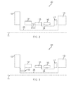
Figure 2 is a schematic section of a first gas turbine engine in accordance with the present invention; -
Figure 3 is a schematic section of a second gas turbine engine in accordance with the present invention. - With reference to
Figure 1 , a ducted fan gas turbine engine generally indicated at 10 has a principal and rotational axis 11. The engine 10 comprises, in axial flow series, anair intake 12, apropulsive fan 13, an intermediate pressure compressor 14, a high-pressure compressor 15, combustion equipment 16, a high-pressure turbine 17, an intermediate pressure turbine 18, a low-pressure turbine 19 and a coreengine exhaust nozzle 20. A nacelle 21 generally surrounds the engine 10 and defines theintake 12, a bypass duct 22 and a bypass exhaust nozzle 23. Thefan 13 is circumferentially surrounded by afan casing 26, which is supported by an annular array ofoutlet guide vanes 27. - The gas turbine engine 10 works in a conventional manner so that air entering the intake 11 is accelerated by the
fan 13 to produce two air flows: a first air flow into the intermediate pressure compressor 14 and a second air flow which passes through a bypass duct 22 to provide propulsive thrust. The intermediate pressure compressor 14 compresses the air flow directed into it before delivering that air to thehigh pressure compressor 15 where further compression takes place. The compressed air exhausted from the high-pressure compressor 15 is directed into the combustion equipment 16 where it is mixed with fuel and the mixture combusted. The resultant hot combustion products then expand through, and thereby drive the high, intermediate and low-pressure turbines 17, 18, 19 before being exhausted through thenozzle 20 to provide additional propulsive thrust. The high, intermediate and low-pressure turbines 17, 18, 19 respectively drive the high andintermediate pressure compressors 15, 14 and thefan 13 by interconnectingshafts - Referring to
Figure 2 , where like components have the same reference numerals as inFigure 1 , a new gas turbine engine 30 comprises twoturbines 17, 19 and threecompressors low pressure turbine 19 drives thefan 13 viashaft 26 similarly as seen inFigure 1 . The high pressure turbine 17 drives thehigh pressure compressor 15 viashaft 24. However, in this arrangement there is no intermediate turbine (18 inFigure 1 ) and no respective shaft (25 inFigure 1 ). Instead the intermediate compressor 14 is connected to thehigh pressure shaft 24 via a gearbox 32. In this first embodiment of the present invention, the gearbox 32 is arranged to drive the intermediate compressor 14 at a lower rotational speed than thehigh pressure compressor 15 /high pressure shaft 24. Accordingly, the high pressure turbine 17 is required to drive both the intermediate pressure compressor 14 and thehigh pressure compressor 15 and is therefore an increased capacity to a conventional three-shaft high pressure turbine. In particular, a two stage rotor turbine is provided. - In a second embodiment of the present invention, referring to
Figure 3 , thelow pressure turbine 19 drives thefan 13 vialow pressure shaft 26 again similarly to the engine shown inFigure 1 . However, thelow pressure shaft 26 is connected via an overdrive gearbox 33 to the intermediate compressor 14. The high pressure turbine 17 drives only thehigh pressure compressor 15 viashaft 24. In this arrangement there is no intermediate turbine (18 inFigure 1 ) and no respective shaft (25). In this second embodiment, the overdrive gearbox 33 is arranged to drive the intermediate compressor 14 at a higher rotational speed than thelow pressure compressor 13/low pressure shaft 26. Accordingly, the high pressure turbine 17 is required to drive both the intermediate pressure compressor 14 and thelow pressure compressor 13 and is therefore an increased capacity to a conventional three-shaft low pressure turbine. In particular, additional rotor stages in the low pressure turbine may be provided. - In either of these arrangements of this gas turbine engine 30 the three
compressors main shafts - For each application of the present invention, each
compressor 14, 15 may comprise any desirable number of rotor and stator stages. Nonetheless, the total number of turbine stages will be reduced from that of an equivalent power, three-shaft engine. - The gearboxes 32, 33 are preferably configured as an epicyclic gearbox as is well known in the art. However, a simple spur gearbox or other suitable device could be used.
Claims (5)
- A gas turbine engine (30) comprising an intermediate compressor (14) and two shafts (24, 26) connecting respective high and low pressure turbines (17, 19) and compressors (13, 15) respectively is characterised by the intermediate pressure compressor (14) connecting to either the high pressure shaft (24) or the low pressure shaft (26) via a gearbox (32, 33).
- The gas turbine engine (30) as claimed in claim 1 wherein the intermediate compressor is rotated at a speed between that of the high and low compressors.
- The gas turbine engine (30) as claimed in any one of claims 1-2 wherein the engine configured with the intermediate pressure compressor (14) connecting to the high pressure shaft (24) and the gearbox (32) is a reduction gearbox.
- The gas turbine engine (30) as claimed in any one of claims 1-2 wherein the engine configured with the intermediate pressure compressor (14) connecting to the low pressure shaft (26) the gearbox (33) is an overdrive gearbox.
- The gas turbine engine (30) as claimed in any one of claims 1-4 wherein the high pressure turbine (17) comprises two or more rotor stages.
Applications Claiming Priority (1)
| Application Number | Priority Date | Filing Date | Title |
|---|---|---|---|
| GBGB0903935.5A GB0903935D0 (en) | 2009-03-09 | 2009-03-09 | Gas turbine engine |
Publications (1)
| Publication Number | Publication Date |
|---|---|
| EP2233721A1 true EP2233721A1 (en) | 2010-09-29 |
Family
ID=40600661
Family Applications (1)
| Application Number | Title | Priority Date | Filing Date |
|---|---|---|---|
| EP10153070A Withdrawn EP2233721A1 (en) | 2009-03-09 | 2010-02-09 | Gas turbine engine |
Country Status (3)
| Country | Link |
|---|---|
| US (1) | US20100223904A1 (en) |
| EP (1) | EP2233721A1 (en) |
| GB (1) | GB0903935D0 (en) |
Cited By (6)
| Publication number | Priority date | Publication date | Assignee | Title |
|---|---|---|---|---|
| WO2014177836A1 (en) * | 2013-05-01 | 2014-11-06 | Derwent Aviation Consulting Ltd | Compressor system |
| WO2015006162A1 (en) | 2013-07-12 | 2015-01-15 | United Technologies Corporation | Three spool geared turbofan with low pressure compressor drive gear system |
| EP2859202A4 (en) * | 2012-06-07 | 2015-07-15 | United Technologies Corp | Single turbine driving dual compressors |
| EP2956649A4 (en) * | 2013-02-13 | 2016-10-12 | United Technologies Corp | Gas turbine engine geared architecture |
| CN110177921A (en) * | 2017-01-23 | 2019-08-27 | 通用电气公司 | The three rotary shaft gas-turbine units with staggered turbine |
| EP3667042A3 (en) * | 2018-12-10 | 2020-08-19 | United Technologies Corporation | Low pressure compressor control for a gas turbine engine |
Families Citing this family (9)
| Publication number | Priority date | Publication date | Assignee | Title |
|---|---|---|---|---|
| US10018119B2 (en) * | 2012-04-02 | 2018-07-10 | United Technologies Corporation | Geared architecture with inducer for gas turbine engine |
| GB201219544D0 (en) * | 2012-10-31 | 2012-12-12 | Rolls Royce Deutschland | Geared compressor for gas turbine engine |
| US9752500B2 (en) * | 2013-03-14 | 2017-09-05 | Pratt & Whitney Canada Corp. | Gas turbine engine with transmission and method of adjusting rotational speed |
| US9853581B2 (en) * | 2013-03-15 | 2017-12-26 | Rolls-Royce Corporation | Lifing and performance optimization limit management for turbine engine |
| WO2015130386A2 (en) * | 2013-12-12 | 2015-09-03 | United Technologies Corporation | Turbomachinery with high relative velocity |
| US10669946B2 (en) | 2015-06-05 | 2020-06-02 | Raytheon Technologies Corporation | Geared architecture for a gas turbine engine |
| US10746181B2 (en) | 2016-08-22 | 2020-08-18 | Raytheon Technologies Corporation | Variable speed boost compressor for gas turbine engine cooling air supply |
| US10677159B2 (en) * | 2017-10-27 | 2020-06-09 | General Electric Company | Gas turbine engine including a dual-speed split compressor |
| US11578663B2 (en) * | 2018-09-11 | 2023-02-14 | Pratt & Whitney Canada Corp. | Engine family platform design |
Citations (6)
| Publication number | Priority date | Publication date | Assignee | Title |
|---|---|---|---|---|
| GB2198791A (en) * | 1986-08-20 | 1988-06-22 | Rolls Royce Plc | A geared turbofan gas turbine engine with a booster compressor |
| DE3933776A1 (en) * | 1989-10-10 | 1991-04-18 | Mtu Muenchen Gmbh | Prop-fan aircraft engine with contra-rotating fan rotors - has epicyclic gear train to connect turbines to fan rotors |
| EP0659234A1 (en) * | 1993-07-06 | 1995-06-28 | ROLLS-ROYCE plc | Shaft power transfer in gas turbine engines |
| EP0787895A2 (en) * | 1996-02-02 | 1997-08-06 | ROLLS-ROYCE plc | Improved method of combining ducted fan gas turbine engine modules and aircraft structure |
| GB2411437A (en) * | 2004-02-28 | 2005-08-31 | Rolls Royce Plc | Aircraft gas turbine engine |
| EP1939430A2 (en) | 2006-12-21 | 2008-07-02 | General Electric Company | Turbofan engine assembly and method of assembling same |
Family Cites Families (12)
| Publication number | Priority date | Publication date | Assignee | Title |
|---|---|---|---|---|
| US2981063A (en) * | 1957-06-17 | 1961-04-25 | Wickman Axel Charles | Variable speed power transmission mechanisms |
| GB1120658A (en) * | 1967-04-20 | 1968-07-24 | Rolls Royce | Power plant for a helicopter |
| GB1484898A (en) * | 1974-09-11 | 1977-09-08 | Rolls Royce | Ducted fan gas turbine engine |
| GB8630754D0 (en) * | 1986-12-23 | 1987-02-04 | Rolls Royce Plc | Turbofan gas turbine engine |
| US6158210A (en) * | 1998-12-03 | 2000-12-12 | General Electric Company | Gear driven booster |
| US20050183540A1 (en) * | 2004-02-25 | 2005-08-25 | Miller Guy W. | Apparatus for driving an accessory gearbox in a gas turbine engine |
| US20080219833A1 (en) * | 2004-12-01 | 2008-09-11 | United Technologies Corporation | Inducer for a Fan Blade of a Tip Turbine Engine |
| US7552582B2 (en) * | 2005-06-07 | 2009-06-30 | Honeywell International Inc. | More electric aircraft power transfer systems and methods |
| US7694505B2 (en) * | 2006-07-31 | 2010-04-13 | General Electric Company | Gas turbine engine assembly and method of assembling same |
| US7832193B2 (en) * | 2006-10-27 | 2010-11-16 | General Electric Company | Gas turbine engine assembly and methods of assembling same |
| US7966806B2 (en) * | 2006-10-31 | 2011-06-28 | General Electric Company | Turbofan engine assembly and method of assembling same |
| US8161728B2 (en) * | 2007-06-28 | 2012-04-24 | United Technologies Corp. | Gas turbines with multiple gas flow paths |
-
2009
- 2009-03-09 GB GBGB0903935.5A patent/GB0903935D0/en not_active Ceased
-
2010
- 2010-02-09 EP EP10153070A patent/EP2233721A1/en not_active Withdrawn
- 2010-02-12 US US12/704,634 patent/US20100223904A1/en not_active Abandoned
Patent Citations (6)
| Publication number | Priority date | Publication date | Assignee | Title |
|---|---|---|---|---|
| GB2198791A (en) * | 1986-08-20 | 1988-06-22 | Rolls Royce Plc | A geared turbofan gas turbine engine with a booster compressor |
| DE3933776A1 (en) * | 1989-10-10 | 1991-04-18 | Mtu Muenchen Gmbh | Prop-fan aircraft engine with contra-rotating fan rotors - has epicyclic gear train to connect turbines to fan rotors |
| EP0659234A1 (en) * | 1993-07-06 | 1995-06-28 | ROLLS-ROYCE plc | Shaft power transfer in gas turbine engines |
| EP0787895A2 (en) * | 1996-02-02 | 1997-08-06 | ROLLS-ROYCE plc | Improved method of combining ducted fan gas turbine engine modules and aircraft structure |
| GB2411437A (en) * | 2004-02-28 | 2005-08-31 | Rolls Royce Plc | Aircraft gas turbine engine |
| EP1939430A2 (en) | 2006-12-21 | 2008-07-02 | General Electric Company | Turbofan engine assembly and method of assembling same |
Cited By (17)
| Publication number | Priority date | Publication date | Assignee | Title |
|---|---|---|---|---|
| EP2859202A4 (en) * | 2012-06-07 | 2015-07-15 | United Technologies Corp | Single turbine driving dual compressors |
| EP3961016A1 (en) * | 2013-02-13 | 2022-03-02 | Raytheon Technologies Corporation | Gas turbine engine geared architecture |
| US11286863B2 (en) | 2013-02-13 | 2022-03-29 | Raytheon Technologies Corporation | Gas turbine engine geared architecture |
| EP2956649A4 (en) * | 2013-02-13 | 2016-10-12 | United Technologies Corp | Gas turbine engine geared architecture |
| US10119475B2 (en) | 2013-02-13 | 2018-11-06 | United Technologies Corporation | Gas turbine engine geared architecture |
| US20190153959A1 (en) * | 2013-02-13 | 2019-05-23 | United Technologies Corporation | Gas turbine engine geared architecture |
| CN105164385A (en) * | 2013-05-01 | 2015-12-16 | 德稳航空咨询有限公司 | Compressor system |
| WO2014177836A1 (en) * | 2013-05-01 | 2014-11-06 | Derwent Aviation Consulting Ltd | Compressor system |
| CN105164385B (en) * | 2013-05-01 | 2017-04-26 | 德稳航空咨询有限公司 | Compressor system |
| US9890704B2 (en) | 2013-05-01 | 2018-02-13 | Derwent Aviation Consulting Ltd. | Compressor system |
| EP3019728A4 (en) * | 2013-07-12 | 2016-07-27 | United Technologies Corp | Three spool geared turbofan with low pressure compressor drive gear system |
| US10330017B2 (en) | 2013-07-12 | 2019-06-25 | United Technologies Corporation | Three spool geared turbofan with low pressure compressor drive gear system |
| WO2015006162A1 (en) | 2013-07-12 | 2015-01-15 | United Technologies Corporation | Three spool geared turbofan with low pressure compressor drive gear system |
| CN110177921A (en) * | 2017-01-23 | 2019-08-27 | 通用电气公司 | The three rotary shaft gas-turbine units with staggered turbine |
| CN110177921B (en) * | 2017-01-23 | 2022-06-14 | 通用电气公司 | Three-spool gas turbine engine with staggered turbine sections |
| EP3667042A3 (en) * | 2018-12-10 | 2020-08-19 | United Technologies Corporation | Low pressure compressor control for a gas turbine engine |
| US11566567B2 (en) | 2018-12-10 | 2023-01-31 | Raytheon Technologies Corporation | Low pressure compressor control for a gas turbine engine |
Also Published As
| Publication number | Publication date |
|---|---|
| US20100223904A1 (en) | 2010-09-09 |
| GB0903935D0 (en) | 2009-04-22 |
Similar Documents
| Publication | Publication Date | Title |
|---|---|---|
| EP2233721A1 (en) | Gas turbine engine | |
| EP1653064B1 (en) | Gas turbine engine with counter rotating blades | |
| US9726113B2 (en) | Turbine engine assembly and methods of assembling same | |
| US9017028B2 (en) | Turbine engine with contra-rotating non-ducted propellers | |
| CN104937251B (en) | Engine framework with reverse rotation monoblock type driver and without stator turbine | |
| EP1921290B1 (en) | Turbofan engine assembly | |
| EP2992198B1 (en) | Two shaft turbo machine | |
| US7832193B2 (en) | Gas turbine engine assembly and methods of assembling same | |
| CA2612031C (en) | Turbofan engine assembly and method of assembling same | |
| EP1626002B1 (en) | Gas turbine engine turbine assembly | |
| CN109386384A (en) | Gas-turbine unit | |
| US10677159B2 (en) | Gas turbine engine including a dual-speed split compressor | |
| US8292570B2 (en) | Low pressure turbine with counter-rotating drives for single spool | |
| EP2128419A1 (en) | Three-spool gas turbine engine | |
| EP3020953B1 (en) | Gas turbine engine | |
| GB2408072A (en) | Contra rotatable turbine system | |
| US8956108B2 (en) | Geared fan assembly | |
| CN112211732A (en) | Gas turbine engine generator | |
| EP3594447B1 (en) | Gas turbine engine outlet guide vanes |
Legal Events
| Date | Code | Title | Description |
|---|---|---|---|
| PUAI | Public reference made under article 153(3) epc to a published international application that has entered the european phase |
Free format text: ORIGINAL CODE: 0009012 |
|
| 17P | Request for examination filed |
Effective date: 20100823 |
|
| AK | Designated contracting states |
Kind code of ref document: A1 Designated state(s): AT BE BG CH CY CZ DE DK EE ES FI FR GB GR HR HU IE IS IT LI LT LU LV MC MK MT NL NO PL PT RO SE SI SK SM TR |
|
| AX | Request for extension of the european patent |
Extension state: AL BA RS |
|
| RIC1 | Information provided on ipc code assigned before grant |
Ipc: F02C 3/113 20060101ALI20110111BHEP Ipc: F02C 3/067 20060101AFI20110111BHEP Ipc: F02C 3/107 20060101ALI20110111BHEP Ipc: F02C 7/275 20060101ALI20110111BHEP Ipc: F02C 7/36 20060101ALI20110111BHEP |
|
| RAP1 | Party data changed (applicant data changed or rights of an application transferred) |
Owner name: ROLLS-ROYCE PLC |
|
| 17Q | First examination report despatched |
Effective date: 20160525 |
|
| STAA | Information on the status of an ep patent application or granted ep patent |
Free format text: STATUS: THE APPLICATION IS DEEMED TO BE WITHDRAWN |
|
| 18D | Application deemed to be withdrawn |
Effective date: 20161005 |