EP1652679A2 - Tintenbehalter und Drucker - Google Patents
Tintenbehalter und Drucker Download PDFInfo
- Publication number
- EP1652679A2 EP1652679A2 EP05256047A EP05256047A EP1652679A2 EP 1652679 A2 EP1652679 A2 EP 1652679A2 EP 05256047 A EP05256047 A EP 05256047A EP 05256047 A EP05256047 A EP 05256047A EP 1652679 A2 EP1652679 A2 EP 1652679A2
- Authority
- EP
- European Patent Office
- Prior art keywords
- ink
- cartridge
- main body
- carriage
- ink cartridge
- Prior art date
- Legal status (The legal status is an assumption and is not a legal conclusion. Google has not performed a legal analysis and makes no representation as to the accuracy of the status listed.)
- Withdrawn
Links
- 238000003860 storage Methods 0.000 claims abstract description 51
- 239000012530 fluid Substances 0.000 claims abstract description 24
- 238000004891 communication Methods 0.000 claims description 5
- 230000000717 retained effect Effects 0.000 claims description 4
- 239000002184 metal Substances 0.000 description 13
- 238000005192 partition Methods 0.000 description 13
- 230000004048 modification Effects 0.000 description 8
- 238000012986 modification Methods 0.000 description 8
- 238000000465 moulding Methods 0.000 description 8
- 238000003780 insertion Methods 0.000 description 6
- 230000037431 insertion Effects 0.000 description 6
- 230000007547 defect Effects 0.000 description 4
- 238000011161 development Methods 0.000 description 4
- 230000008878 coupling Effects 0.000 description 3
- 238000010168 coupling process Methods 0.000 description 3
- 238000005859 coupling reaction Methods 0.000 description 3
- 230000003292 diminished effect Effects 0.000 description 3
- 238000004519 manufacturing process Methods 0.000 description 3
- 238000007639 printing Methods 0.000 description 3
- 239000003086 colorant Substances 0.000 description 2
- 230000006835 compression Effects 0.000 description 2
- 238000007906 compression Methods 0.000 description 2
- 239000006260 foam Substances 0.000 description 2
- 230000006872 improvement Effects 0.000 description 2
- 230000007246 mechanism Effects 0.000 description 2
- 238000000034 method Methods 0.000 description 2
- 239000002245 particle Substances 0.000 description 2
- 230000009467 reduction Effects 0.000 description 2
- 230000015572 biosynthetic process Effects 0.000 description 1
- 230000002950 deficient Effects 0.000 description 1
- 230000003467 diminishing effect Effects 0.000 description 1
- 230000005489 elastic deformation Effects 0.000 description 1
- 230000002708 enhancing effect Effects 0.000 description 1
- 230000006870 function Effects 0.000 description 1
- 238000005304 joining Methods 0.000 description 1
- 238000012423 maintenance Methods 0.000 description 1
- 238000000638 solvent extraction Methods 0.000 description 1
- 229920003002 synthetic resin Polymers 0.000 description 1
- 239000000057 synthetic resin Substances 0.000 description 1
Images


Classifications
-
- B—PERFORMING OPERATIONS; TRANSPORTING
- B41—PRINTING; LINING MACHINES; TYPEWRITERS; STAMPS
- B41J—TYPEWRITERS; SELECTIVE PRINTING MECHANISMS, i.e. MECHANISMS PRINTING OTHERWISE THAN FROM A FORME; CORRECTION OF TYPOGRAPHICAL ERRORS
- B41J2/00—Typewriters or selective printing mechanisms characterised by the printing or marking process for which they are designed
- B41J2/005—Typewriters or selective printing mechanisms characterised by the printing or marking process for which they are designed characterised by bringing liquid or particles selectively into contact with a printing material
- B41J2/01—Ink jet
- B41J2/17—Ink jet characterised by ink handling
- B41J2/175—Ink supply systems ; Circuit parts therefor
- B41J2/17503—Ink cartridges
- B41J2/17553—Outer structure
Definitions
- the present invention relates to an ink cartridge containing ink fluid in an ink storage chamber, as well as to a printer equipped with the ink cartridge.
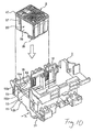
- Fig. 10 shows a related-art example of a carriage to be set in an inkjet printer and a related-art example of an ink cartridge set in this carriage.
- the carriage 1 shown in Fig. 10 has a first cartridge mount section 13 for housing a color ink cartridge on an upper surface of a carriage main body 11 which is reciprocally driven by an unillustrated carriage drive mechanism in a direction (direction of arrow A in the drawing) orthogonal to a transport direction of print paper in a printer; and a second cartridge mount section 15 for housing a black ink cartridge.
- a print head 21 is provided on a lower portion of the carriage main body 11, and ejects, on print paper and in the form of ink droplets of predetermined particle sizes, ink fluids supplied from the respective ink cartridges mounted on the first and second cartridge mount sections 13, 15.
- the ink cartridge 3 shown in Fig. 10 is a color ink cartridge independently containing ink fluids of three colors; namely, cyan, magenta, and yellow, for color printing purpose.
- this ink cartridge 3 comprises a cartridge main body 35 which forms three ink storage chambers 31, 32, and 33, whose upper portions are opened, by means of partitioning; porous elastic bodies (foam bodies) 37 which are housed and retained by the respective ink storage chambers 31, 32, and 33; ink supply ports 39 formed in bottom sections of the respective ink storage chambers 31, 32, and 33 for supplying to the print head 21 of the inkjet printer the ink fluids, which are stored in the respective ink storage chambers 31, 32, and 33 while the porous elastic bodies 37 are impregnated with the ink fluids ⁇ ; elastic-body retaining ribs 43 which are projectingly provided on the interior surface of a front wall 41 of the cartridge main body 35 ⁇ the front wall forming the respective ink storage chambers 31, 32, and 33 by partitioning ⁇ and retain the porous elastic bodies 37 in a predetermined compressed state; and a cover member 47 bonded to the upper surface of the cartridge main body 35 so as to cover the upper open sections of the
- the front wall 41 of the cartridge main body 35 is a side-face wall provided essentially perpendicular to the bottom wall of the cartridge main body 35.
- the elastic-body retaining ribs 43 provided projectingly on the interior surface of the front wall 41 press one end face 37a of the corresponding porous elastic body 37, to thus retain the porous elastic body 37 as being compressed at a predetermined compression rate and, simultaneously, to ensure a space 42 required to prevent occurrence of fluctuations in pressure, which would otherwise be caused by sucking an ink fluid at a negative pressure, between the one end face 37a of the porous elastic body 37 and the interior surface of the front wall 41.
- a data recorder 51 is attached to an exterior surface of the front wall 41 of the cartridge main body 35.
- This data recorder 51 is formed from a memory element which enables reading or writing of data pertaining to the quantities of ink remaining in the respective ink storage chambers 31, 32, and 33 and the date of manufacture of the ink cartridge; and a plurality of connection terminals 51a by way of which information is input to or output from the memory element.
- the connection terminals 51a are attached to the exterior surface of the front wall 41 so as to become exposed on the outer surface of the cartridge main body 35.
- a carriage-side connection terminal 53 to be electrically connected to the connection terminal 51a is provided, in correspondence to the position on the ink cartridge 3 where the data recorder 51 is to be provided, on the first cartridge mount section 13 of the carriage main body 11 into which the ink cartridge 3 is to be mounted.
- the carriage-side connection terminal 53 is provided in the interior surface of a front partition 13a which partitions the first cartridge mount section 13.
- the carriage-side connection terminal 53 is connected to a control circuit in a printer, and the carriage-side connection terminal 53 and the connection terminal 51a are electrically connected together. As a result, the control circuit in the printer can read or write data from and into the data recorder 51 on the ink cartridge 3.
- the carriage main body 11 is provided with an erroneous-insertion-prevention groove 54 which prevents insertion of the ink cartridge 3 into the first cartridge mount section 13 while being oriented in a wrong direction; and a positioning groove 55 for aligning the position of the connection terminal 51a on the ink cartridge 3 with the carriage-side connection terminal 53 of the carriage main body 11 in connection with the ink cartridge 3 inserted into the first cartridge mount section 13 in an appropriate orientation.
- the erroneous-insertion-prevention groove 54 is formed at an upper end portion of a side partition 13b which forms the first cartridge mount section 13, and the positioning groove 55 is formed at an upper end portion of the front partition 13a.
- an erroneous-insertion-prevention rib 57 to fit into the erroneous-insertion-prevention groove 54 is projectingly formed on one side wall 38 of the cartridge main body 35.
- a positioning rib 58 to fit into the positioning groove 55 is projectingly provided on an exterior surface of the front wall 41 equipped with the data recorder 51.
- the ink cartridge 3 cannot be inserted into the first cartridge mount section 13.
- positional adjustment is performed such that the extremity of the positioning rib 58 comes into intimate contact with a positioning surface 55b, which is formed on one side of the positioning groove 55, by means of a tapered surface 55a formed in the positioning groove 55.
- the plurality of connection terminals 51a are accurately connected to the carriage-side connection terminal 53 (see, e.g., Patent Document 1).
- Patent Document 1 JP-A-2004-1430
- the ink cartridge as discussed above suffers from the following problems:
- the positioning rib 58 provided on the related-art ink cartridge 3 shown in Fig. 11 is a single piece of thin-walled plate.
- the carriage main body 11 is manufactured by a method for ejecting and molding synthetic resin, the rib exhibits superior moldability.
- the rib has become deficient in rigidity strength, there may be a possibility of positioning accuracy being reduced by elastic deformation, and the like, which would otherwise be caused when the rib comes into contact with the positioning groove 55.
- an object of the present invention is to solve the problem and to provide an ink cartridge which can maintain high positional accuracy when being set to a carriage of a printer by virtue of having a positioning projection of high rigidity strength, as well as to provide a printer.
- the outer dimension of the ink cartridge 3 must match the dimension of the first cartridge mount section 13 of the carriage main body 11, in order to achieve electrical conduction between the connection terminal 51a and the carriage-side connection terminal 53 and positional alignment of the ink supply port 39 with an ink supply passage for the print head 21. For instance, even when the porous elastic bodies 37 are made compact, changes must be prevented from arising in the outer dimension of the principal section.
- the metal mold for the carriage main body 11 as well as metal mold used for manufacturing the ink cartridge 3 must be newly created, which in turn entails high development cost.
- the storage space for the porous elastic body 37 in each of the ink storage chambers 31, 32, and 33 is diminished by means of increasing the protruding length of the elastic-body retaining ribs 43 which protrude toward the inside of the ink storage chambers 31, 32, and 33, thereby maintaining the outer dimension of the ink cartridge.
- Another object of the present invention is to solve the above-described problem and to provide an ink cartridge which enables miniaturization of a porous elastic body and reduction of ink remaining in the cartridge, as well as to provide a printer.
- An embodiment of the present invention is directed to an ink cartridge having a cartridge main body forming an ink storage chamber, an ink supply port formed in a bottom section of the ink storage chamber for supplying an ink fluid stored in the ink storage chamber to a print head mounted on a carriage of a printer, and a positioning protrusion projectingly provided on a side-face wall of the cartridge main body, the positioning protrusion fitting into a positioning groove of the carriage, so that the cartridge main body is positioned at a cartridge mount section of the carriage.
- the positioning protrusion has a pair of plate-like sections opposing each other with a partition therebetween, and a joint section which joins the plate-like sections together. An outer surface of the one plate-like section is set as a positioning surface which comes into contact with the positioning groove.
- a pair of mutually-opposing plate-like sections are coupled together by means of a joint section, thereby forming a positioning protrusion. Even when each of the plate-like sections is a single piece of thin plate, rigidity strength, which is higher than that achieved in a case where each of the plate-like sections is solely used for positioning, can be achieved.
- the positioning protrusion preferably includes the pair of plate-like sections and the joint section, and is preferably formed integrally into a bag structure whose inside is hollowed by a relief which is in mutual communication with the ink storage chamber.
- the structure of the positioning protrusion becomes a bag structure, whereby a further improvement in rigidity strength can be expected.
- the positioning protrusion being formed into a hollow structure, occurrence of molding distortions, such as sink marks, can be suppressed, thereby enabling an attempt can be made to improve dimensional accuracy of the positioning protrusion.
- a data recorder having a connection terminal electrically connected to a carriage-side connection terminal provided on a cartridge mount section of the carriage is preferably mounted on the side-face wall of the cartridge main body.
- connection terminal of the data recorder attached to the side-face wall of the cartridge main body is matched, with high accuracy, to the carriage-side connection terminal provided on the cartridge mount section. Hence, the operation reliability of the data recorder can be enhanced.
- the positioning protrusion is formed by joining a pair of mutually-opposing plate-like sections. Even when each of the plate-like sections is a single piece of thin plate, high rigidity strength can be acquired.
- each of the pair of plate-like sections constituting the positioning protrusion and the joint section requires only a thin-walled structure. Therefore, molding distortions, such as sink marks, tend not to arise, thereby enabling an attempt to improve dimensional accuracy.
- an ink cartridge capable of maintaining high positional accuracy when being mounted to the carriage of the printer, as well as a printer.
- Another embodiment of the present invention is directed to an ink cartridge having a cartridge main body forming an ink storage chamber, a porous elastic body retained in the ink storage chamber, an ink fluid stored in the ink storage chamber while the porous elastic body is impregnated with the ink fluid, an ink supply port formed in a bottom section of the ink storage chamber for supplying the ink fluid stored in the ink storage chamber to a print head of the printer, and an elastic-body retaining rib which is provided projectingly on an interior surface of a side-face wall of the cartridge main body and retains the porous elastic body in a compressed state.
- the ink cartridge comprises recessed sections, which cause an interior surface of the side-face wall to protrude toward the inside of the ink storage chamber, formed on the side-face wall of the cartridge main body on which the elastic-body retaining rib is projectingly provided, such that a projecting height of the elastic-body retaining rib with reference to an interior surface of the side-face wall becomes smaller.
- the interior surface of the side-face wall is caused to protrude toward the inside of the ink storage chamber by means of the recessed sections formed on the side-face wall of the cartridge main body on which the elastic-body retaining ribs are projectingly provided.
- the projecting height of the elastic-body retaining ribs with reference to the interior surface of the side-face wall can be reduced.
- the space ⁇ which is formed between the interior surface of the side-face wall of the cartridge main body on which the elastic-body retaining ribs are projectingly provided and the one end face of the porous elastic body pressed by the elastic-body retaining ribs ⁇ is suppressed to a minimum-required space. Occurrence of pressure fluctuations, which would otherwise arise during suction of an ink fluid at a negative pressure, can be prevented, and the amount of ink remaining during replacement of the cartridge can be diminished.
- the recessed sections which cause the interior surface of the side-face wall to protrude toward the inside of the ink storage chamber are solely limited to the range where the elastic-body retaining ribs are projectingly provided. Areas outside the range can be maintained to outer dimensions in the related art. The outer dimensions of the principal sections of the ink cartridge which contribute to attachment of the ink cartridge to the carriage on the printer can be maintained to the conventional dimensions.
- modifications in the metal mold associated with miniaturization of the porous elastic bodies are limited solely to the metal mold for a cartridge main body.
- a known metal mold for a carriage can also be used, and development cost attributable to modifications in the metal molds can also be reduced.
- the side-face wall of the cartridge main body preferably stands at an inclination with reference to a bottom wall of the cartridge main body such that a space formed between the interior surface of the side-face wall of the cartridge main body, on which the elastic-body retaining rib is projectingly provided, and one end face of the porous elastic body pressed by the elastic-body retaining rib gradually becomes larger in size upward from the bottom wall of the cartridge main body.
- the ink remaining in the space is guided to the porous elastic body by means of the interior surface of the inclined side-face wall. Consequently, the quantity of ink remaining in the space can be reduced to a great extent.
- Another embodiment of the present invention is directed to a printer, in which the ink cartridge having the above-described configuration is attached to a carriage with a print head mounted thereon.
- the printer comprises: guide protrusions which are provided on a carriage main body of the carriage opposing the recessed sections formed on the side-face wall of the cartridge main body and which come into slidable contact with exterior surfaces of the recessed sections to thus insert and guide the ink cartridge when the ink cartridge is attached to the carriage.
- the space ⁇ which is formed between the interior surface of the side-face wall of the cartridge main body on which the elastic-body retaining ribs are projectingly provided and the one end face of the porous elastic body pressed by the elastic-body retaining ribs ⁇ is suppressed to a minimum-required space. Occurrence of pressure fluctuations, which would otherwise arise during suction of an ink fluid at a negative pressure, can be prevented, and the amount of ink remaining during replacement of the cartridge can be diminished.
- an ink cartridge which enables miniaturization of a porous elastic body and reduction of ink remaining in the cartridge and provides superior operability, as well as a printer.
- Fig. 1 is a perspective view of an ink cartridge of an embodiment of the present invention as well as a carriage of a printer to which the ink cartridge is to be mounted.
- Fig. 2 is a perspective view achieved when the ink cartridge shown in Fig. 1 is viewed from an oblique lower rear position.
- Fig. 3 is a perspective view achieved when the ink cartridge shown in Fig. 1 is viewed from an oblique lower front position.
- Fig. 4 is a front view of the ink cartridge shown in Fig. 1.
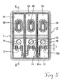
- Fig. 5 is a top view of the ink cartridge main body of the cartridge main body shown in Fig. 1.
- Fig. 6 is a cross-sectional view taken along line B-B shown in Fig. 5.
- Fig. 7 is an enlarged cross-sectional view of the principal section for describing insertion guidance performed when the ink cartridge shown in Fig. 1 is mounted to the carriage main body.
- Fig. 8 is an enlarged cross-sectional view of the principal section for describing a section for positioning the ink cartridge and the carriage main body shown in Fig. 1.
- Fig. 9 is an enlarged cross-sectional view of the principal section showing a modification of the positioning protrusion shown in Fig. 8.
- Fig. 10 is a perspective view showing a carriage and an ink cartridge, both pertaining to a related-art inkjet printer.
- Fig. 11 is an exploded perspective view of the ink cartridge shown in Fig. 10.
- Fig. 1 is a perspective view of an ink cartridge and a carriage of a printer equipped with the ink cartridge, both of which pertain to one embodiment of the present invention
- Fig. 2 is a perspective view of the ink cartridge shown in Fig. 1 when viewed froman obliquely-lower rear position
- Fig. 3 is a perspective view of the ink cartridge shown in Fig. 1 from an obliquely-lower front position
- Fig. 4 is a front view of the ink cartridge shown in Fig. 1
- Fig. 5 is a top view of a cartridge main body shown in Fig. 1
- Fig. 6 is a cross-sectional view taken along line B-B shown in Fig. 5.
- an ink cartridge 7 of the present embodiment is mounted to a carriage 6 attached to the inkjet printer.
- the carriage 6 of the present embodiment comprises a first cartridge mount section 63 which stores a color ink cartridge on an upper surface of a carriage main body 61 which is reciprocally driven by an unillustrated carriage drive mechanism in a direction (direction of arrow A in the drawing) orthogonal to a transport direction of print paper in the printer; and a second cartridge mount section 65 which houses a black ink cartridge.
- a print head 21 is mounted on a lower portion of the carriage main body 61, and ejects, in the form of ink droplets of predetermined particle sizes on print paper, ink fluids supplied from respective ink cartridges attached to the first and second ink cartridge mount sections 63, 65.
- the ink cartridge 7 shown in Figs. 1 through 6 is a color ink cartridge for color printing purpose which independently houses ink fluids of three colors; namely, cyan, magenta, and yellow.
- the ink cartridge 7 of the present embodiment comprises a cartridge main body 71 which partitions three ink storage chambers 31, 32, and 33 whose upper portions are opened; porous elastic bodies (foam bodies) 37 housed and retained in the respective ink storage chambers 31, 32, and 33; ink supply ports 39 formed in bottom sections of the respective ink storage chambers 31, 32, and 33 for supplying to the print head 21 of the inkjet printer the ink fluids, which are stored in the respective ink storage chambers 31, 32, and 33 while the porous elastic bodies 37 are impregnated with the ink fluids ⁇ ; elastic-body-retaining ribs 75 which are projectingly provided on an interior surface 73a of a front wall 73 of the cartridge main body 71 ⁇ the front wall partitions the respective ink storage chambers 31, 32, and 33 ⁇ and retain the porous elastic bodies 37 in a predetermined compressed state; and a cover member 47 bonded to the upper surface of the cartridge main body
- the cartridge main body of the black ink cartridge which is to be attached to the second cartridge mounting section 65 of the carriage main body 61 and which independently contains a black ink fluid for monochrome printing purpose, is essentially identical in configuration with the cartridge main body 71 of the color ink cartridge, except that the number of the ink storage chambers into which the porous elastic bodies 37 are to be set is limited to one.
- the cartridge main body 71 of the color ink cartridge will be described hereinbelow, and detailed description of the cartridge main body of the black ink cartridge is omitted.
- the front wall 73 of the cartridge main body 71 of the present embodiment is a side-face wall standing upright on the bottom wall of the cartridge main body 71.
- the elastic-body retaining ribs 5 projectingly provided on the interior surface 73a of the front wall 73 press one end face 37a of the porous elastic body 37, thereby retaining the porous elastic body 37 while compressing the same at a predetermined compression rate.
- the front wall 73 of the cartridge main body 71 of the present embodiment is provided with recessed sections 83 such that the projecting height T of the elastic-body-retaining ribs 75 in relation to the interior surface 73a of the front wall 73 becomes smaller, wherein the recessed sections 83 are formed by causing a range L of a lower portion of the interior surface 73a ⁇ into which the elastic-body-retaining ribs 75 are projected ⁇ to protrude toward the insides of the ink storage chambers 31, 32, and 33.
- a space 77 is formed between the interior surface 73a of the front wall 73 of the cartridge main body 71 ⁇ on which the elastic-body retaining ribs 75 are projectingly formed ⁇ and an end face 37a of the porous elastic body 37 pressed by the elastic-body-retaining ribs 75.
- the front wall 73 located between the recessed sections 83 stands at an inclination of ⁇ with reference to the normal line on the bottom wall of the cartridge main body 71 such that the space 77 becomes gradually wider with upward movement from the bottom wall of the cartridge main body 71.
- a recorder mounting section 81 on which a data recorder 51 is to be mounted is provided on the exterior surface of the cartridge main body 71.
- the data recorder mount section 81 becomes relatively protruded to the position of the exterior surface of the front wall 41 of the related-art ink cartridge main body 35 in Fig. 11, but is level with the exterior surface of the front wall 41 of the related-art ink cartridge main body 35 shown in Fig. 11.
- the data recorder 51 is formed from a memory element which enables reading or writing of data pertaining to the quantities of ink remaining in the respective ink storage chambers 31, 32, and 33 and the date of manufacture of the ink cartridge; and a plurality of connection terminals 51a by way of which data are input to or output from the memory element.
- the connection terminals 51a are attached to the front surface of the recorder mount section 81 of the front wall 73 so as to become exposed on the outer surface of the cartridge main body 71.
- a carriage-side connection terminal 53 to be electrically connected to the connection terminal 51a is provided, in correspondence to the position on the ink cartridge 7 where the data recorder 51 is to be provided, on the first cartridge mount section 63 of the carriage main body 61 into which the ink cartridge 7 is to be mounted.
- the carriage-side connection terminal 53 is provided in the interior surface of a front partition 63a which partitions the first cartridge mount section 63.
- the carriage-side connection terminal 53 is connected to a control circuit in a printer, and the carriage-side connection terminal 53 and the connection terminal 51a are electrically connected together.
- the control circuit in the printer can read or write data from and into the data recorder 51 on the ink cartridge 7.
- the positioning accuracy of the ink cartridge 7 to the first cartridge mount section 63 of the carriage main body 61 must be enhanced.
- the carriage main body 61 is provided with an erroneous-insertion-prevention groove 54 which prevents insertion of the ink cartridge 7 into the first cartridge mount section 63 with an incorrect orientation; and a positioning groove 85 for aligning the position of the connection terminal 51a on the ink cartridge 7 with the carriage-side connection terminal 53 of the carriage main body 61 in connection with the ink cartridge 7 inserted into the first cartridge mount section 63 with an appropriate orientation.
- the erroneous-insertion-prevention groove 54 is formed at an upper end portion of a side partition 63b which partitions the first cartridge mount section 63, and the positioning groove 85 is formed at an upper end portion of the front partition 63a.
- an erroneous-insertion-prevention rib 57 to fit into the erroneous-insertion-prevention groove 54 is projectingly formed on one side wall 78 of the cartridge main body 71.
- a positioning protuberance 87 to fit into the positioning groove 85 is projectingly provided on an exterior surface of a front wall 73 equipped with the data recorder 51.
- the ink cartridge 7 cannot be inserted into the first cartridge mount section 63.
- positional adjustment is performed such that the extremity of the positioning protuberance 87 comes into intimate contact with a positioning surface 85b, which is formed on one side of the positioning groove 85, by means of a tapered surface 85a formed in the positioning groove 85.
- the plurality of connection terminals 51a are accurately connected to the carriage-side connection terminal 53.
- the positioning protuberance 87 of the present embodiment is formed into a bag structure comprising a pair of plate-like sections 87a, 87b which mutually oppose while being horizontally separated from each other; an extremity joint wall 87c coupling e_xtremities of the plate-like sections 87a, 87b; and a joint bottom wall 87d which is a joint section for coupling lower edges of the left and right plate-like sections 87a, 87b together.
- the rigidity strength of the positioning protuberance is enhanced.
- a rib made of a single piece of thin-walled plate such as the positioning rib 58 of the related-art ink cartridge 3 shown in Fig. 11, is merely formed into a thick-walled plate in order to enhance the rigidity strength of the rib, dimensional accuracy of the rib becomes difficult to maintain upon occurrence of molding defects such as sink marks.
- the positioning protuberance 87 of the present embodiment enables improvement in rigidity strength and maintenance of dimensional accuracy, by integrally molding the positioning protuberance 87 into a bag structure whose inside is hollowed by a relief remaining in mutual communication with the ink storage chamber 33 at the time of formation of the cartridge main body 71.
- the pair of plate-like sections 87a, 87b which oppose each other with the hollow section therebetween function as a pair of ribs to fit into the positioning groove 85 of the carriage 6.
- An outer surface of the one plate-like section 87a is set as a positioning surface which comes into contact with the positioning surface 85b of the positioning groove 85.
- the positioning protuberance 87 of the present embodiment is formed into a bag structure for enhancing rigidity strength, a different structure may also be adopted, so long as required rigidity strength can be achieved.
- the joint bottom wall 87d which couples the lower edges of the pair of plate-like sections 87a, 87b is omitted, and a partition 87e is interposed between the ink storage chambers 33.
- a structure equipped with a relief remaining in mutual communication with the outside of cartridges can also be employed.
- the carriage 6 of the inkjet printer of the present embodiment is provided with a pair of guide protrusions 89, 89, wherein the pair of guide protrusions 89, 89 are provided on the carriage main body 61 opposing the recessed sections 83 formed on the front wall 73 of the cartridge main body 71 and which come into slidable contact with and insert to guide exterior surfaces 83a of the recessed sections 83 when the ink cartridge 7 is attached to the carriage 6.
- the pair of guide protrusions 89, 89 of the present embodiment are arranged such that both side surfaces of the recorder mount section 81, which is imparted with a raised shape by the exterior surfaces 83a of the recessed sections 83 formed on both sides of the recorder mount section 81, are sandwiched between the exterior surfaces.
- the entirety of the recorder mount section 81 is formed as an engagement protrusion section which is to fit between the pair of guide protrusions 89, 89.
- the positioning protrusion 87 is formed by coupling the pair of mutually-opposing plate-like sections 87a, 87b to the extremity joint wall 87c and the joint bottom wall 87d. Even when the plate-like sections 87a, 87b correspond to pieces of thin-walled plate sections, higher rigidity strength can be achieved as compared with a case where the singlepiece of thin-walled plate-like section, such as the positioning rib 58 in the related-art ink cartridge 3 shown in Fig. 11, is solely used for positioning.
- the ink cartridge 7 when the ink cartridge 7 is attached to the carriage 6 of the printer, high positioning accuracy can be maintained by the positioning protrusion 87 having high rigidity strength.
- the pair of plate-like sections 87a, 87b, the extremity joint wall 87c, and the joint bottom wall 87d, all of which constitute the positioning protrusion 87, require only a structure where individual sections have a small wall thickness. Hence, molding defects, such as sinkmarks, tend not to arise, and dimensional accuracy can be expected.
- the data recorder 51 ⁇ which is equipped with the connection terminal 51a electrically connected to the carriage-side connection terminal 53 provided in the cartridge mount section 63 of the carriage 6 ⁇ is attached to the front wall 73 of the cartridge main body 71 of the ink cartridge 7 of the present embodiment.
- the connection terminal 51a of the data recorder 51 is matched with the carriage-side connection terminal 53 provided on the cartridge mount section 63 by the above-mentioned positioning protrusion 87 with high accuracy. Hence, operation reliability of the data recorder 51 can be enhanced.
- the interior surface 73a of the front wall 73 is caused to protrude inside the ink storage chambers 31, 32, and 33 by means of the recessed sections 83 provided on both sides of the front wall 73 of the cartridge main body 71 on which the elastic-body retaining ribs 75 are projectingly provided.
- the projecting height T of the elastic-body retaining ribs 75 with reference to the interior surface 73a of the front wall 73 can be reduced by the amount corresponding to the extent to which the interior surface 73a projects inside.
- pressure fluctuations which would otherwise arise during negative suction of an ink fluid, can be prevented, thereby diminishing the amount of ink remaining during replacement of the cartridge.
- the outer dimension of the principal section of the ink cartridge 7, which pertains to the first cartridge mount section 61 of the carriage 6 of the printer, can be maintained to a related-art dimension.
- modifications in the metal mold associated with miniaturization of the porous elastic body 37, or the like are limited solely to the metal mold for the cartridge main body 71.
- a known metal mold can also be used, in its present form, for the metal mold for the carriage 6. Even when modifications are made, the modifications can be minimized. Hence, development cost incurred by modifications in the metal mold, and the like, can be reduced.
- the front wall 73 stands at an inclination ⁇ with reference to the normal line on the bottom wall of the cartridge main body 71.
- the space 77 formed between the interior surface 73a of the front wall 73 and the one end face 37a of the porous elastic body 37 gradually increases in size upward from the bottom wall of the cartridge main body 71.
- the ink remaining in the space 77 is guided to the porous elastic body 37 by the interior surface 73a of the inclined front wall 73, so that the amount of ink remaining in the space 77 can be reduced to a great extent.
- the recorder mount section 81 formed from the recessed sections 83 formed on both sides of the front wall 73 of the cartridge main body 71 is formed as an engagement protrusion section which fits between the pair of guide protrusions 89, 89 which oppose the recorder mount section 81 and are projectingly provided on the carriage main body 61. Accordingly, operability required when the ink cartridge 7 is mounted to the carriage 6 can be enhanced.
- the configuration of the ink storage chamber, that of the cartridge main body, that of the ink supply port, that of the positioning protrusions, that of the cartridge mount section, that of the positioning groove, that of the upper portion of the plate, that of the joint section, and those of other sections, all these sections belonging to the ink cartridge and the printer of the present invention, are not limited to the configurations of the embodiment. As a matter of course, various modes can be adopted on the basis of the gist of the present invention.
Landscapes
- Ink Jet (AREA)
Applications Claiming Priority (2)
| Application Number | Priority Date | Filing Date | Title |
|---|---|---|---|
| JP2004288699A JP4529626B2 (ja) | 2004-09-30 | 2004-09-30 | インクカートリッジ及びプリンタ |
| JP2004288698A JP2006102964A (ja) | 2004-09-30 | 2004-09-30 | インクカートリッジ及びプリンタ |
Publications (2)
| Publication Number | Publication Date |
|---|---|
| EP1652679A2 true EP1652679A2 (de) | 2006-05-03 |
| EP1652679A3 EP1652679A3 (de) | 2006-11-22 |
Family
ID=35871204
Family Applications (1)
| Application Number | Title | Priority Date | Filing Date |
|---|---|---|---|
| EP05256047A Withdrawn EP1652679A3 (de) | 2004-09-30 | 2005-09-28 | Tintenbehalter und Drucker |
Country Status (2)
| Country | Link |
|---|---|
| EP (1) | EP1652679A3 (de) |
| RU (1) | RU2302344C2 (de) |
Cited By (1)
| Publication number | Priority date | Publication date | Assignee | Title |
|---|---|---|---|---|
| EP1892103A2 (de) | 2006-08-23 | 2008-02-27 | Canon Kabushiki Kaisha | Tintenbehälter |
Families Citing this family (1)
| Publication number | Priority date | Publication date | Assignee | Title |
|---|---|---|---|---|
| JP5393400B2 (ja) * | 2008-11-18 | 2014-01-22 | キヤノン株式会社 | 液体吐出ヘッド |
Citations (3)
| Publication number | Priority date | Publication date | Assignee | Title |
|---|---|---|---|---|
| JP2004001430A (ja) | 2002-03-29 | 2004-01-08 | Seiko Epson Corp | インクカートリッジ及び記録装置 |
| JP2004288698A (ja) | 2003-03-19 | 2004-10-14 | Rohm Co Ltd | チップ型led |
| JP2004288699A (ja) | 2003-03-19 | 2004-10-14 | Seiko Epson Corp | 半導体装置及びその製造方法 |
Family Cites Families (12)
| Publication number | Priority date | Publication date | Assignee | Title |
|---|---|---|---|---|
| ATE160316T1 (de) * | 1991-01-18 | 1997-12-15 | Canon Kk | Tintenstrahlaufzeichnungskopf und aufzeichnungsgerät damit versehen |
| EP0860285B1 (de) * | 1991-12-11 | 2002-03-06 | Canon Kabushiki Kaisha | Tintenstrahlpatrone |
| US6293662B1 (en) * | 1998-01-19 | 2001-09-25 | Canon Kabushiki Kaisha | Ink tank coupling method, ink jet recording apparatus, and ink tank |
| SG100699A1 (en) * | 1998-05-13 | 2003-12-26 | Seiko Epson Corp | Ink cartridge for ink-jet printing apparatus |
| ATE477934T1 (de) * | 1998-05-18 | 2010-09-15 | Seiko Epson Corp | Tintenstrahldruckvorrichtung und zugehörige tintenpatrone |
| US6224192B1 (en) * | 1998-10-06 | 2001-05-01 | Hewlett-Packard Company | Inkjet printing systems using a modular print cartridge assembly |
| TW541247B (en) * | 2000-01-31 | 2003-07-11 | Hewlett Packard Co | Latch and handle arrangement for a replaceable ink container |
| US6666542B2 (en) * | 2001-03-30 | 2003-12-23 | Brother Kogyo Kabushiki Kaisha | Ink cartridge for printer or the like and ink cartridge positioning and locking mechanism |
| KR20040020146A (ko) * | 2002-08-29 | 2004-03-09 | 삼성전자주식회사 | 잉크카트리지 |
| SG107613A1 (en) * | 2002-09-11 | 2004-12-29 | Inke Pte Ltd | Ink tank (inkjet ink cartridge) |
| ATE390289T1 (de) * | 2002-11-26 | 2008-04-15 | Seiko Epson Corp | Tintenpatrone |
| US7168801B2 (en) * | 2003-01-28 | 2007-01-30 | Samsung Electronics Co., Ltd. | Ink cartridge |
-
2005
- 2005-09-28 EP EP05256047A patent/EP1652679A3/de not_active Withdrawn
- 2005-09-29 RU RU2005130351/12A patent/RU2302344C2/ru not_active IP Right Cessation
Patent Citations (3)
| Publication number | Priority date | Publication date | Assignee | Title |
|---|---|---|---|---|
| JP2004001430A (ja) | 2002-03-29 | 2004-01-08 | Seiko Epson Corp | インクカートリッジ及び記録装置 |
| JP2004288698A (ja) | 2003-03-19 | 2004-10-14 | Rohm Co Ltd | チップ型led |
| JP2004288699A (ja) | 2003-03-19 | 2004-10-14 | Seiko Epson Corp | 半導体装置及びその製造方法 |
Cited By (5)
| Publication number | Priority date | Publication date | Assignee | Title |
|---|---|---|---|---|
| EP1892103A2 (de) | 2006-08-23 | 2008-02-27 | Canon Kabushiki Kaisha | Tintenbehälter |
| EP1892103A3 (de) * | 2006-08-23 | 2009-04-01 | Canon Kabushiki Kaisha | Tintenbehälter |
| CN101130309B (zh) * | 2006-08-23 | 2010-06-16 | 佳能株式会社 | 墨盒 |
| US8011768B2 (en) | 2006-08-23 | 2011-09-06 | Canon Kabushiki Kaisha | Ink tank |
| US8439491B2 (en) | 2006-08-23 | 2013-05-14 | Canon Kabushiki Kaisha | Ink tank |
Also Published As
| Publication number | Publication date |
|---|---|
| EP1652679A3 (de) | 2006-11-22 |
| RU2005130351A (ru) | 2007-04-27 |
| RU2302344C2 (ru) | 2007-07-10 |
Similar Documents
| Publication | Publication Date | Title |
|---|---|---|
| US7954935B2 (en) | Liquid container with mounting and removal guide for regulating movement of the liquid container | |
| US7552999B2 (en) | Liquid container and circuit board for liquid container | |
| CN101535054B (zh) | 液体容纳容器 | |
| AU2011346241B2 (en) | Cartridge | |
| EP1380429B1 (de) | Tintenpatrone und diese enthaltendes Vakuumverpackungsprodukt | |
| JP4946751B2 (ja) | 容器ホルダ、液体消費装置及び液体収容容器 | |
| US7438401B2 (en) | Inkjet recording apparatus and ink cartridge | |
| JP2020019280A (ja) | カートリッジ、印刷材供給システム、印刷装置、液体収容容器、印刷システム、及び端子接続構造 | |
| EP1095777B1 (de) | Tintenpatrone zur Benutzung in einem Tintenstrahlaufzeichnungsgerät | |
| JP7651980B2 (ja) | カートリッジ、および、印刷システム | |
| CN100352658C (zh) | 液体容器 | |
| EP1880858A1 (de) | Druckvorrichtung und Tintenkartusche dafür | |
| US9114623B2 (en) | Liquid cartridge and image forming apparatus with same | |
| KR20010013265A (ko) | 교환가능한 잉크 용기 및 오프-축형 프린팅 시스템과오프-축형 프린팅 시스템내로 잉크 용기를 삽입하는 방법 | |
| JP2008273173A (ja) | 液体収容容器 | |
| JP2007301979A (ja) | 液体収容容器 | |
| TWI429541B (zh) | 液體容器 | |
| JP4153915B2 (ja) | インクカートリッジ | |
| JP2002113881A (ja) | インクカートリッジの接続構造およびこれを用いたインクジェット式記録装置 | |
| EP1652679A2 (de) | Tintenbehalter und Drucker | |
| CN1907719B (zh) | 液体容器 | |
| JP4529626B2 (ja) | インクカートリッジ及びプリンタ | |
| JP2006102964A (ja) | インクカートリッジ及びプリンタ | |
| JP5055867B2 (ja) | 液体収容容器 | |
| CN119704886B (zh) | 墨盒、注墨方法、墨盒组件及打印设备 |
Legal Events
| Date | Code | Title | Description |
|---|---|---|---|
| PUAI | Public reference made under article 153(3) epc to a published international application that has entered the european phase |
Free format text: ORIGINAL CODE: 0009012 |
|
| AK | Designated contracting states |
Kind code of ref document: A2 Designated state(s): AT BE BG CH CY CZ DE DK EE ES FI FR GB GR HU IE IS IT LI LT LU LV MC NL PL PT RO SE SI SK TR |
|
| AX | Request for extension of the european patent |
Extension state: AL BA HR MK YU |
|
| PUAL | Search report despatched |
Free format text: ORIGINAL CODE: 0009013 |
|
| AK | Designated contracting states |
Kind code of ref document: A3 Designated state(s): AT BE BG CH CY CZ DE DK EE ES FI FR GB GR HU IE IS IT LI LT LU LV MC NL PL PT RO SE SI SK TR |
|
| AX | Request for extension of the european patent |
Extension state: AL BA HR MK YU |
|
| 17P | Request for examination filed |
Effective date: 20070425 |
|
| 17Q | First examination report despatched |
Effective date: 20070605 |
|
| AKX | Designation fees paid |
Designated state(s): AT BE BG CH CY CZ DE DK EE ES FI FR GB GR HU IE IS IT LI LT LU LV MC NL PL PT RO SE SI SK TR |
|
| GRAP | Despatch of communication of intention to grant a patent |
Free format text: ORIGINAL CODE: EPIDOSNIGR1 |
|
| RTI1 | Title (correction) |
Free format text: PRINTER |
|
| STAA | Information on the status of an ep patent application or granted ep patent |
Free format text: STATUS: THE APPLICATION IS DEEMED TO BE WITHDRAWN |
|
| 18D | Application deemed to be withdrawn |
Effective date: 20100213 |