EP1652573A1 - Method and device for manufacturing nanofilter media - Google Patents
Method and device for manufacturing nanofilter media Download PDFInfo
- Publication number
- EP1652573A1 EP1652573A1 EP05023437A EP05023437A EP1652573A1 EP 1652573 A1 EP1652573 A1 EP 1652573A1 EP 05023437 A EP05023437 A EP 05023437A EP 05023437 A EP05023437 A EP 05023437A EP 1652573 A1 EP1652573 A1 EP 1652573A1
- Authority
- EP
- European Patent Office
- Prior art keywords
- set forth
- catalyst nanoparticles
- media
- reactor
- gas
- Prior art date
- Legal status (The legal status is an assumption and is not a legal conclusion. Google has not performed a legal analysis and makes no representation as to the accuracy of the status listed.)
- Granted
Links
Images


Classifications
-
- B—PERFORMING OPERATIONS; TRANSPORTING
- B01—PHYSICAL OR CHEMICAL PROCESSES OR APPARATUS IN GENERAL
- B01D—SEPARATION
- B01D39/00—Filtering material for liquid or gaseous fluids
- B01D39/14—Other self-supporting filtering material ; Other filtering material
- B01D39/20—Other self-supporting filtering material ; Other filtering material of inorganic material, e.g. asbestos paper, metallic filtering material of non-woven wires
- B01D39/2055—Carbonaceous material
- B01D39/2065—Carbonaceous material the material being fibrous
-
- B—PERFORMING OPERATIONS; TRANSPORTING
- B82—NANOTECHNOLOGY
- B82B—NANOSTRUCTURES FORMED BY MANIPULATION OF INDIVIDUAL ATOMS, MOLECULES, OR LIMITED COLLECTIONS OF ATOMS OR MOLECULES AS DISCRETE UNITS; MANUFACTURE OR TREATMENT THEREOF
- B82B3/00—Manufacture or treatment of nanostructures by manipulation of individual atoms or molecules, or limited collections of atoms or molecules as discrete units
-
- B—PERFORMING OPERATIONS; TRANSPORTING
- B01—PHYSICAL OR CHEMICAL PROCESSES OR APPARATUS IN GENERAL
- B01D—SEPARATION
- B01D39/00—Filtering material for liquid or gaseous fluids
-
- B—PERFORMING OPERATIONS; TRANSPORTING
- B01—PHYSICAL OR CHEMICAL PROCESSES OR APPARATUS IN GENERAL
- B01D—SEPARATION
- B01D39/00—Filtering material for liquid or gaseous fluids
- B01D39/14—Other self-supporting filtering material ; Other filtering material
- B01D39/16—Other self-supporting filtering material ; Other filtering material of organic material, e.g. synthetic fibres
- B01D39/1607—Other self-supporting filtering material ; Other filtering material of organic material, e.g. synthetic fibres the material being fibrous
- B01D39/1623—Other self-supporting filtering material ; Other filtering material of organic material, e.g. synthetic fibres the material being fibrous of synthetic origin
-
- B—PERFORMING OPERATIONS; TRANSPORTING
- B01—PHYSICAL OR CHEMICAL PROCESSES OR APPARATUS IN GENERAL
- B01D—SEPARATION
- B01D39/00—Filtering material for liquid or gaseous fluids
- B01D39/14—Other self-supporting filtering material ; Other filtering material
- B01D39/20—Other self-supporting filtering material ; Other filtering material of inorganic material, e.g. asbestos paper, metallic filtering material of non-woven wires
- B01D39/2068—Other inorganic materials, e.g. ceramics
- B01D39/2082—Other inorganic materials, e.g. ceramics the material being filamentary or fibrous
-
- B—PERFORMING OPERATIONS; TRANSPORTING
- B82—NANOTECHNOLOGY
- B82Y—SPECIFIC USES OR APPLICATIONS OF NANOSTRUCTURES; MEASUREMENT OR ANALYSIS OF NANOSTRUCTURES; MANUFACTURE OR TREATMENT OF NANOSTRUCTURES
- B82Y30/00—Nanotechnology for materials or surface science, e.g. nanocomposites
-
- B—PERFORMING OPERATIONS; TRANSPORTING
- B82—NANOTECHNOLOGY
- B82Y—SPECIFIC USES OR APPLICATIONS OF NANOSTRUCTURES; MEASUREMENT OR ANALYSIS OF NANOSTRUCTURES; MANUFACTURE OR TREATMENT OF NANOSTRUCTURES
- B82Y40/00—Manufacture or treatment of nanostructures
-
- C—CHEMISTRY; METALLURGY
- C01—INORGANIC CHEMISTRY
- C01B—NON-METALLIC ELEMENTS; COMPOUNDS THEREOF; METALLOIDS OR COMPOUNDS THEREOF NOT COVERED BY SUBCLASS C01C
- C01B32/00—Carbon; Compounds thereof
- C01B32/15—Nano-sized carbon materials
- C01B32/158—Carbon nanotubes
- C01B32/16—Preparation
- C01B32/162—Preparation characterised by catalysts
-
- C—CHEMISTRY; METALLURGY
- C23—COATING METALLIC MATERIAL; COATING MATERIAL WITH METALLIC MATERIAL; CHEMICAL SURFACE TREATMENT; DIFFUSION TREATMENT OF METALLIC MATERIAL; COATING BY VACUUM EVAPORATION, BY SPUTTERING, BY ION IMPLANTATION OR BY CHEMICAL VAPOUR DEPOSITION, IN GENERAL; INHIBITING CORROSION OF METALLIC MATERIAL OR INCRUSTATION IN GENERAL
- C23C—COATING METALLIC MATERIAL; COATING MATERIAL WITH METALLIC MATERIAL; SURFACE TREATMENT OF METALLIC MATERIAL BY DIFFUSION INTO THE SURFACE, BY CHEMICAL CONVERSION OR SUBSTITUTION; COATING BY VACUUM EVAPORATION, BY SPUTTERING, BY ION IMPLANTATION OR BY CHEMICAL VAPOUR DEPOSITION, IN GENERAL
- C23C16/00—Chemical coating by decomposition of gaseous compounds, without leaving reaction products of surface material in the coating, i.e. chemical vapour deposition [CVD] processes
- C23C16/02—Pretreatment of the material to be coated
- C23C16/0272—Deposition of sub-layers, e.g. to promote the adhesion of the main coating
- C23C16/0281—Deposition of sub-layers, e.g. to promote the adhesion of the main coating of metallic sub-layers
-
- D—TEXTILES; PAPER
- D01—NATURAL OR MAN-MADE THREADS OR FIBRES; SPINNING
- D01F—CHEMICAL FEATURES IN THE MANUFACTURE OF ARTIFICIAL FILAMENTS, THREADS, FIBRES, BRISTLES OR RIBBONS; APPARATUS SPECIALLY ADAPTED FOR THE MANUFACTURE OF CARBON FILAMENTS
- D01F9/00—Artificial filaments or the like of other substances; Manufacture thereof; Apparatus specially adapted for the manufacture of carbon filaments
- D01F9/08—Artificial filaments or the like of other substances; Manufacture thereof; Apparatus specially adapted for the manufacture of carbon filaments of inorganic material
- D01F9/10—Artificial filaments or the like of other substances; Manufacture thereof; Apparatus specially adapted for the manufacture of carbon filaments of inorganic material by decomposition of organic substances
-
- D—TEXTILES; PAPER
- D01—NATURAL OR MAN-MADE THREADS OR FIBRES; SPINNING
- D01F—CHEMICAL FEATURES IN THE MANUFACTURE OF ARTIFICIAL FILAMENTS, THREADS, FIBRES, BRISTLES OR RIBBONS; APPARATUS SPECIALLY ADAPTED FOR THE MANUFACTURE OF CARBON FILAMENTS
- D01F9/00—Artificial filaments or the like of other substances; Manufacture thereof; Apparatus specially adapted for the manufacture of carbon filaments
- D01F9/08—Artificial filaments or the like of other substances; Manufacture thereof; Apparatus specially adapted for the manufacture of carbon filaments of inorganic material
- D01F9/12—Carbon filaments; Apparatus specially adapted for the manufacture thereof
- D01F9/127—Carbon filaments; Apparatus specially adapted for the manufacture thereof by thermal decomposition of hydrocarbon gases or vapours or other carbon-containing compounds in the form of gas or vapour, e.g. carbon monoxide, alcohols
- D01F9/1271—Alkanes or cycloalkanes
-
- D—TEXTILES; PAPER
- D01—NATURAL OR MAN-MADE THREADS OR FIBRES; SPINNING
- D01F—CHEMICAL FEATURES IN THE MANUFACTURE OF ARTIFICIAL FILAMENTS, THREADS, FIBRES, BRISTLES OR RIBBONS; APPARATUS SPECIALLY ADAPTED FOR THE MANUFACTURE OF CARBON FILAMENTS
- D01F9/00—Artificial filaments or the like of other substances; Manufacture thereof; Apparatus specially adapted for the manufacture of carbon filaments
- D01F9/08—Artificial filaments or the like of other substances; Manufacture thereof; Apparatus specially adapted for the manufacture of carbon filaments of inorganic material
- D01F9/12—Carbon filaments; Apparatus specially adapted for the manufacture thereof
- D01F9/127—Carbon filaments; Apparatus specially adapted for the manufacture thereof by thermal decomposition of hydrocarbon gases or vapours or other carbon-containing compounds in the form of gas or vapour, e.g. carbon monoxide, alcohols
- D01F9/133—Apparatus therefor
-
- B—PERFORMING OPERATIONS; TRANSPORTING
- B01—PHYSICAL OR CHEMICAL PROCESSES OR APPARATUS IN GENERAL
- B01D—SEPARATION
- B01D2239/00—Aspects relating to filtering material for liquid or gaseous fluids
- B01D2239/02—Types of fibres, filaments or particles, self-supporting or supported materials
- B01D2239/025—Types of fibres, filaments or particles, self-supporting or supported materials comprising nanofibres
-
- B—PERFORMING OPERATIONS; TRANSPORTING
- B01—PHYSICAL OR CHEMICAL PROCESSES OR APPARATUS IN GENERAL
- B01D—SEPARATION
- B01D2239/00—Aspects relating to filtering material for liquid or gaseous fluids
- B01D2239/02—Types of fibres, filaments or particles, self-supporting or supported materials
- B01D2239/0258—Types of fibres, filaments or particles, self-supporting or supported materials comprising nanoparticles
-
- B—PERFORMING OPERATIONS; TRANSPORTING
- B01—PHYSICAL OR CHEMICAL PROCESSES OR APPARATUS IN GENERAL
- B01D—SEPARATION
- B01D2239/00—Aspects relating to filtering material for liquid or gaseous fluids
- B01D2239/06—Filter cloth, e.g. knitted, woven non-woven; self-supported material
- B01D2239/0604—Arrangement of the fibres in the filtering material
- B01D2239/0613—Woven
-
- B—PERFORMING OPERATIONS; TRANSPORTING
- B01—PHYSICAL OR CHEMICAL PROCESSES OR APPARATUS IN GENERAL
- B01D—SEPARATION
- B01D2239/00—Aspects relating to filtering material for liquid or gaseous fluids
- B01D2239/06—Filter cloth, e.g. knitted, woven non-woven; self-supported material
- B01D2239/0604—Arrangement of the fibres in the filtering material
- B01D2239/0618—Non-woven
-
- B—PERFORMING OPERATIONS; TRANSPORTING
- B01—PHYSICAL OR CHEMICAL PROCESSES OR APPARATUS IN GENERAL
- B01D—SEPARATION
- B01D2239/00—Aspects relating to filtering material for liquid or gaseous fluids
- B01D2239/10—Filtering material manufacturing
Definitions
- the present invention relates to a method of manufacturing nanofilter media, which are porous media composed of nanotubes or nanofibers formed on conventional microfilter media serving as a substrate by directly synthesizing and growing the nanotubes or nanofibers on the substrate, and to a device for manufacturing the nanofilter media.
- nanofilter media obtained by attaching nanofiber to conventional microfilter media are known to improve the filtration efficiency without a large change in the permeability of the filter.
- the use of the nanofiber to manufacture the filter media results in novel filter media which are advantageous because they cause lower pressure drop while maintaining filtration efficiency equal to that of the conventional microfilter.
- filters made of the nanofibers are known to exhibit excellent ability to filter ultrafine contaminant particles, that is, nanoparticles.
- the filter is formed by applying the nanofiber on the surface of the microfilter media, the fine contaminant particles are collected on the surface of the filter media, and do not infiltrate deep into the region of the microfilter serving as a substrate, resulting in improved cleaning performance and restorability.
- nanofilter media coated with the nanofiber have been manufactured by spinning the nanofibers on the fibrous microfilter serving as a substrate using an electrospinning technique.
- the electrospinning technique is a top-down manner in which the nanofibers are spun from the polymer solution by applying an electrical field between the capillary end and the substrate, the diameter of the nanofiber cannot be decreased below a lower limit.
- an object of the present invention is to provide a method of manufacturing nanofilter media, which are composed of nanotubes or nanofibers having a diameter unable to realize using a conventional process of manufacturing nanofibers, by directly synthesizing and growing the nanotubes or nanofibers on microfilter media serving as a substrate in a bottom-up manner.
- Another object of the present invention is to provide a device for manufacturing the nanofilter media composed of the nanotubes or nanofibers.
- a method of manufacturing nanofilter media includes loading catalyst nanoparticles into a reactor equipped with microfilter media serving as a substrate to attach the catalyst nanoparticles to the microfilter media, feeding a source gas and a reactive gas onto the catalyst nanoparticles, heating the entire reactor or selectively heating the microfilter media provided in the reactor or the catalyst nanoparticles attached to the microfilter media provided in the reactor to synthesize and grow nanotubes or nanofibers from the heated catalyst nanoparticles, to prepare nanofilter media composed of the synthesized and grown nanotubes or nanofibers.
- the catalyst particles include cobalt, nickel, iron, or alloys thereof.
- the microfilter serving as a substrate includes a fibrous filter, a fabric filter, or a membrane filter.
- the material for the microfilter media may be all of materials including a polymer, silicon oxide (SiO 2 ), alumina (Al 2 O 3 ), ceramics, or metal oxides.
- the catalyst nanoparticles are prepared according to inert gas condensation (IGC) processes such as resistance heating, plasma heating, induction heating or laser heating, chemical vapor condensation (CVC) processes using a resistance coil reactor, a flame reactor, a laser reactor or a plasma reactor, or liquid processes such as direct precipitation, coprecipitation, freeze drying or spray pyrolysis.
- IOC inert gas condensation
- CVC chemical vapor condensation
- the catalyst nanoparticles may include a transition metal, sulfides, carbides, oxides or salts of the transition metal, or an organic compound containing the transition metal.
- the catalyst nanoparticles formed of the transition metal may be prepared from the precursor of the above transition metal supported on the microfilter media serving as a substrate and converted into the transition metal through reduction, sintering, sulfurization or carbonization.
- the method of the present invention is characterized in that the catalyst nanoparticles are supported on the microfilter media serving as a substrate using painting, dipping, spraying or deposition.
- the catalyst nanoparticles formed of the metal sulfide may include metal sulfide obtained by sulfurizing the catalyst nanoparticles of the transition metal with hydrogen sulfide (H 2 S) or thiophene.
- the catalyst nanoparticles formed of the metal sulfide may include nanoparticles formed of a solid particulate mixture comprising the transition metal and sulfur.
- the catalyst nanoparticles formed of the metal sulfide may include nanoparticles in the form of droplets comprising an ionic solution of the transition metal and sulfur.
- the catalyst nanoparticles formed of the organic compound may include nanoparticles in the form of droplets comprising the catalyst precursor in the form of nanodroplets.
- the source gas may include a hydrocarbon gas or a silane gas, depending on the material used to manufacture nanotubes or nanofibers.
- the reactive gas may include an inert gas, hydrogen gas, oxygen gas, or mixtures thereof, and may further include a cocatalyst such as hydrogen sulfide (H 2 S) or thiophene, if required.
- a cocatalyst such as hydrogen sulfide (H 2 S) or thiophene, if required.
- the inert gas may include helium (He) gas or argon (Ar) gas to transport the catalyst nanoparticles or dilute the reactive gas.
- He helium
- Ar argon
- the catalyst nanoparticles may be heated using a resistance heater formed of resistance coils.
- the catalyst nanoparticles may be heated using microwave radiation.
- the catalyst nanoparticles may be heated using electromagnetic induction.
- the catalyst nanoparticles may be heated using laser heating.
- the catalyst nanoparticles may be heated using radio frequency (RF) heating.
- RF radio frequency
- the material for nanotubes or nanofibers may include carbon, silicon, or silicon oxides.
- the nanofilter media may include filter media formed by synthesizing and growing the nanotubes or nanofibers on a conventional microfilter serving as a substrate in a bottom-up manner.
- the nanofilter media may include filter media functioning to simultaneously collect dust and adsorb gas.
- the nanofilter media may include a catalyst filter, an antibiotic filter, or a deodorization filter, able to remove volatile organic compounds (VOCs), sterilize air and perform deodorization if additional metal nanoparticles are deposited on the nanotubes or nanofibers.
- VOCs volatile organic compounds
- the nanofilter media may include high strength filter media having high mechanical strength, heat resistant filter media able to endure high temperatures, or chemical proof filter media which are resistant to predetermined chemicals.
- the catalyst precursor is selected from among ferrocene, iron-pentacarbonyl, dicobalt-octacarbonyl, and nickel-carbonyl.
- the present invention provides a device for manufacturing nanofilter media, including a catalyst nanoparticle forming and feeding unit to form and feed the catalyst nanoparticles, a reactor equipped with microfilter media serving as a substrate to which the catalyst nanoparticles are attached, a reactive gas feeding unit to feed a source gas and a reactive gas into the reactor, and a heating unit to heat the catalyst nanoparticles provided into the reactor.
- the catalyst nanoparticle forming and feeding unit includes a catalyst nanoparticle forming part, and further includes a nanoparticle classification part or a concentration controlling part to control the concentration of the nanoparticles, if required. Also, a vaporous catalyst precursor feeding part is further included to feed the precursor of the catalyst nanoparticles in vapor phase into the reactor.
- the reactor includes a filter holder or a quartz tube in which the microfilter media are provided.
- the reactor includes a conveyor line through which the microfilter media are continuously transported.
- the heating unit includes a power part to apply current to the resistance heater formed of resistance coils mounted around the reactor.
- the heating unit includes a microwave generator to generate microwaves and a microwave guide connected to the above reactor to guide the microwaves.
- the heating unit includes a high frequency coil mounted around the reactor and a power part to apply high frequency current to the high frequency coil.
- the heating unit includes an RF generator mounted around the reactor.
- the heating unit includes a laser generator mounted around the reactor and a lens assembly to concentrate laser light beams generated by the laser generator.
- the nanotubes or nanofibers are synthesized and grown on conventional microfilter media, thereby manufacturing nanofilter media having higher filtration efficiency, in particular, better ability to filter nanoparticles, which are ultrafine particles, compared to a conventional microfilter.
- microfilter media having low pressure drop and low filtration efficiency are used as a substrate, and thus, the nanotubes or nanofibers are appropriately synthesized and grown on the substrate, to manufacture filter media having lower pressure drop and the filtration efficiency superior to conventional filter media, that is, higher filter quality (FQ).
- FQ filter quality
- nanotubes or nanofibers in particular, carbon nanotubes or carbon nanofibers formed of carbon, are synthesized and grown to manufacture the nanofilter media, which then are formed into chemical filters able to simultaneously adsorb and remove contaminant gas and filter particulate matter.
- the metal nanoparticles are further deposited on the synthesized nanotubes or nanofibers, thereby manufacturing filter media of a catalyst filter, an antibiotic filter, or a deodorization filter able to remove VOCs, sterilize air, or perform deodorization.
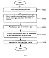
- FIG. 1 is a flowchart illustrating the process of manufacturing the nanofilter media including nanotubes or nanofibers synthesized and grown on microfilter media serving as a substrate, according to the present invention.
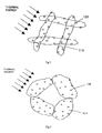
- FIGS. 2 and 3 are views schematically illustrating the heating of the catalyst nanoparticles attached to the surface of the fibrous or fabric microfilter media and the surface of the membrane microfilter media while maintaining appropriate dispersion rates, according to the present invention.
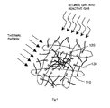
- FIGS. 4 and 5 are views schematically illustrating the synthesis and growth of the nanotubes or nanofibers on the microfilter media, according to the present invention.
- FIG. 6 is a view schematically illustrating the device for manufacturing the nanofilter media including the synthesized and grown nanotubes or nanofibers, according to the present invention.
- the method of manufacturing the nanofilter media is performed using the device for manufacturing the nanofilter media depicted in FIG. 6.
- the device for manufacturing the nanofilter media which is shown in FIG. 6, is used to realize the preparation of the nanofilter media by synthesizing and growing the nanotubes or nanofibers from the catalyst nanoparticles attached to the microfilter media serving as a substrate.
- the device for manufacturing the nanofilter media according to the present invention includes a reactor 100 of FIG. 6 equipped with microfilter media serving as a substrate 110 of FIG. 2 or 111 of FIG. 3 having catalyst nanoparticles 120 of FIG. 2 or 3 attached to the substrate, in which the catalyst nanoparticles 120 formed of a transition metal are attached to the surface of the fibrous or fabric microfilter media 110 or the surface of the membrane microfilter media 111.
- the reactor 100 includes a quartz tube, a filter holder, or a conveyor line to transport the substrate.
- the device of the present invention includes a heating unit 200 to simultaneously heat the catalyst nanoparticles 120 and the substrate 110 or 111 provided into the reactor 100, or selectively heat only the catalyst nanoparticles 120.
- the heating unit 200 may be equipped with a microwave generator 210 of FIG. 6 to generate microwaves and a microwave guide 220 of FIG. 6 to guide the generated microwaves into the reactor.
- the above device includes a gas feeding unit 300 of FIG. 6 to feed the source gas and the reactive gas required to synthesize the nanotubes or nanofibers in the reactor 100, a catalyst nanoparticle forming and feeding unit 400 of FIG. 6 to form the catalyst nanoparticles 120 and feed the formed catalyst nanoparticles 120 into the reactor 100, and a discharging unit 500 of FIG. 6 to treat the gas discharged from the reactor 100.
- a gas feeding unit 300 of FIG. 6 to feed the source gas and the reactive gas required to synthesize the nanotubes or nanofibers in the reactor 100
- a catalyst nanoparticle forming and feeding unit 400 of FIG. 6 to form the catalyst nanoparticles 120 and feed the formed catalyst nanoparticles 120 into the reactor 100
- a discharging unit 500 of FIG. 6 to treat the gas discharged from the reactor 100.
- the gas feeding unit 300 is provided with a gas bombe to feed the source gas such as a hydrocarbon gas or a silane gas, the reactive gas such as hydrogen sulfide gas, the cocatalyst gas such as thiophene, the reducing gas such as hydrogen gas, the oxidizing gas such as oxygen, and the carrier gas such as an inert gas.
- the gas feeding unit 300 further includes a mass flow controller (MFC) 310 of FIG. 6 mounted to a pipe line between the gas bombe and the reactor 100 and/or the catalyst nanoparticle forming and feeding unit 400 to control the amount of gas, and an on/off valve 320 of FIG. 6.
- the gas bombe, the MFC 310, and the on/off valve 320 may each be provided in a plurality of sets, if necessary.
- the catalyst nanoparticles 120 are provided in the form of the transition metal, the precursor of the transition metal, or a mixture comprising transition metal and the cocatalyst component such as sulfur on the substrate 110 or 111.
- the catalyst nanoparticle forming and feeding unit 400 which is connected to the reactor 100, is provided.
- the catalyst nanoparticle forming and feeding unit 400 may be operated using any process able to feed the solid or liquid catalyst or catalyst precursor in the form of aerosol.
- the catalyst nanoparticle forming and feeding unit 400 includes a catalyst nanoparticle forming part 410 of FIG. 6, and further includes a catalyst nanoparticle classification part 420 of FIG. 6 or a concentration controlling part 430 of FIG. 6 to control the concentration of the catalyst nanoparticles, if necessary.
- the catalyst nanoparticles 120 are first formed at step 1000 of FIG. 1.
- the process of forming the catalyst nanoparticles includes all the known processes of synthesizing nanoparticles, modified processes of synthesizing the nanoparticles, or combinations thereof. For example, there are IGC, CVC, aerosol spraying, etc.
- the formed catalyst nanoparticles 120 may be in solid or liquid phase.
- the material for formed catalyst nanoparticles 120 includes a pure transition metal, a transition metal compound, a transition metal precursor, or a transition metal compound containing the sulfur.
- the catalyst nanoparticles 120 formed using the catalyst nanoparticle forming part 410 may be fed into the reactor 100 without change.
- the catalyst nanoparticles 120 formed using the catalyst nanoparticle forming part 410 as in FIG. 6 may be classified into catalyst nanoparticles 120 having a desired diameter using the nanoparticle classification part 420, and then fed into the reactor 100, if required.
- the catalyst nanoparticles 120 formed using the catalyst nanoparticle forming part 410 as in FIG. 6 may be further mixed with the source gas, the reactive gas or the mixture gas thereof, using the concentration controlling part 430 to control the concentration of the nanoparticles, and discharged while the concentration of the catalyst nanoparticles 120 is controlled, and then fed into the reactor 100, if required.
- the catalyst nanoparticles 120 formed using the nanoparticle forming and feeding unit 400 of FIG. 6 are fed into the reactor 100 of FIG. 6, and subsequently, attached to the microfilter media, which have been previously provided in the reactor 100, at step 1100 of FIG. 1.
- microfilter media serving as a substrate 110 or 111 which the catalyst nanoparticles 120 have been previously attached to may be provided into the reactor 100.
- the catalyst nanoparticles 120 formed using the catalyst nanoparticle forming part 410 may be classified into catalyst nanoparticles 120 having a desired diameter using the nanoparticle classification part 420, and the classified catalyst nanoparticles may be attached to the microfilter media serving as a substrate 110 or 111 in the reactor 100.
- the catalyst nanoparticles 120 formed using the catalyst nanoparticle forming part 410, or the catalyst nanoparticles 120 classified using the nanoparticle classification part 420 may be fed into the reactor 100 while the concentration thereof is controlled by the source gas, the reactive gas or the mixture gas thereof additionally fed through the concentration controlling part 430 to control the concentration of the nanoparticles, and thus, may be attached to the microfilter media serving as a substrate 110 or 111.
- the source gas or the reactive gas is fed into the reactor 100 at step 1200 of FIG. 1.
- the source gas is selected depending on the material for nanotubes or nanofibers 130 which are synthesized and grown on the substrate 110 or 111.
- a hydrocarbon gas such as acetylene gas, methane gas, propane gas or benzene may be used as the source gas.
- the reactive gas includes a cocatalyst gas, a reducing gas, an oxidizing gas, a carrier gas, or mixtures thereof.
- the cocatalyst gas is an adjuvant catalyst used to accelerate the synthesis and growth of the nanotubes or nanofibers 130 from the catalyst nanoparticles 120 as in FIG. 4, and is exemplified by hydrogen sulfide (H 2 S) gas and thiophene vapor.
- the hydrogen sulfide gas and the thiophene vapor react with the catalyst nanoparticles 120 of the transition metal while predetermined thermal energy is supplied to the reactor 100, so that the above catalyst nanoparticles 120 are converted into catalyst nanoparticles of transition metal sulfide to decrease the melting point of the catalyst nanoparticles.
- the temperature required to synthesize and grow the nanotubes or nanofibers 130 may be decreased using the catalyst nanoparticles 120 of the transition metal sulfide having a low melting point, deformation and breakage due to deterioration of the substrate may be prevented.
- the reducing gas functions to reduce the catalyst nanoparticles 120 of the transition metal which have been previously oxidized while predetermined thermal energy is supplied to the reactor 100, and is exemplified by hydrogen gas.
- the oxidizing gas may be used for oxidation of a product or a by-product in the reactor 100 during or after synthesis, if required.
- the carrier gas is fed into the reactor 100 along with the above gases to be fed into the reactor 100, and thus, functions to control the concentration of the above gases or the flow rate of gas in the reactor 100, if required.
- a carrier gas includes, for example, an inert gas such as a helium gas or an argon gas, or a nitrogen gas.
- the thermal energy is supplied to the substrate 110 or 111 in the reactor 100, the catalyst nanoparticles 120, or the source gas and the reactive gas to synthesize and grow the nanotubes or nanofibers 130 from the catalyst nanoparticles 120 attached to the substrate 110 or 111 as seen in FIGS. 3 and 4 at step 1300 of FIG. 1.
- the substrate 110 or 111 in the reactor 100, the catalyst nanoparticles 120, or the source gas and the reactive gas may be simultaneously heated, or selectively heated, if necessary.
- the heating unit 200 used to supply the thermal energy to the reactor 100 may be appropriately selected depending on the material of the substrate 100 or 111 in the reactor 100, that is, depending on whether or not the substrate 110 or 111 is required to be protected from heat.
- Such a heating unit 200 which functions to supply the thermal energy to the reactor 100, may include, for example, a resistance coil heater, a microwave radiator, an electromagnetic induction heater, a laser heater, or an RF heater.
- the heating unit 200 may selectively heat the catalyst nanoparticles 120, the substrate 110 or 111, or the source gas and the reactive gas, or may heat the entire reactor.
- the nanotubes or nanofibers 130 are synthesized and grown while maintaining the predetermined porous properties of the microfilter media serving as a substrate 110 or 111 by controlling the process conditions for manufacturing the nanofilter media, including the conditions of the size and the number concentration of the catalyst nanoparticles 120, to obtain desired nanofilter media at step 1400 of FIG. 1.
- the diameter of the synthesized nanotubes or nanofibers 130 may be controlled by adjusting the size of the catalyst nanoparticles 120.
- the distribution degree that is, the density of the nanotubes or nanofibers 130
- the synthesis conditions such as distribution concentration of the catalyst nanoparticles 120, concentration of the source gas, time periods or temperatures required for synthesis, etc.
- the present invention provides a method and device for manufacturing nanofilter media, in which the catalyst nanoparticles are attached to the microfilter media serving as a substrate, from which the nanotubes or nanofibers are synthesized in the presence of the source gas and/or the reactive gas while supplying predetermined energy required to induce the synthetic reaction using a predetermined heating unit.
- the nanofilter media can be obtained by synthesizing and growing the nanotubes or nanofibers from the catalyst nanoparticles in a bottom-up manner.
- the diameter and solidity of the nanotubes or nanofibers which are synthesized and grown may be controlled by the size and the number concentration of the catalyst nanoparticles attached on the microfilter media as a substrate, and other synthesis conditions.
Landscapes
- Chemical & Material Sciences (AREA)
- Engineering & Computer Science (AREA)
- Chemical Kinetics & Catalysis (AREA)
- Nanotechnology (AREA)
- Materials Engineering (AREA)
- Physics & Mathematics (AREA)
- General Chemical & Material Sciences (AREA)
- Textile Engineering (AREA)
- Crystallography & Structural Chemistry (AREA)
- Organic Chemistry (AREA)
- Condensed Matter Physics & Semiconductors (AREA)
- Inorganic Chemistry (AREA)
- Life Sciences & Earth Sciences (AREA)
- Thermal Sciences (AREA)
- Geology (AREA)
- General Physics & Mathematics (AREA)
- Manufacturing & Machinery (AREA)
- Metallurgy (AREA)
- Mechanical Engineering (AREA)
- Ceramic Engineering (AREA)
- Composite Materials (AREA)
- Carbon And Carbon Compounds (AREA)
- Catalysts (AREA)
- Separation Using Semi-Permeable Membranes (AREA)
- Disinfection, Sterilisation Or Deodorisation Of Air (AREA)
- Filtering Materials (AREA)
- Solid-Sorbent Or Filter-Aiding Compositions (AREA)
- Silicon Compounds (AREA)
Abstract
Description
- The present invention relates to a method of manufacturing nanofilter media, which are porous media composed of nanotubes or nanofibers formed on conventional microfilter media serving as a substrate by directly synthesizing and growing the nanotubes or nanofibers on the substrate, and to a device for manufacturing the nanofilter media.
- In general, nanofilter media obtained by attaching nanofiber to conventional microfilter media are known to improve the filtration efficiency without a large change in the permeability of the filter.
- That is, the use of the nanofiber to manufacture the filter media results in novel filter media which are advantageous because they cause lower pressure drop while maintaining filtration efficiency equal to that of the conventional microfilter.
- Further, filters made of the nanofibers are known to exhibit excellent ability to filter ultrafine contaminant particles, that is, nanoparticles. In the case where the filter is formed by applying the nanofiber on the surface of the microfilter media, the fine contaminant particles are collected on the surface of the filter media, and do not infiltrate deep into the region of the microfilter serving as a substrate, resulting in improved cleaning performance and restorability.
- As a result, the lifetime of the filter is lengthened.
- Recently, nanofilter media coated with the nanofiber have been manufactured by spinning the nanofibers on the fibrous microfilter serving as a substrate using an electrospinning technique.
- However, since the electrospinning technique is a top-down manner in which the nanofibers are spun from the polymer solution by applying an electrical field between the capillary end and the substrate, the diameter of the nanofiber cannot be decreased below a lower limit.
- Accordingly, the present invention has been made keeping in mind the above problems occurring in the related art, and an object of the present invention is to provide a method of manufacturing nanofilter media, which are composed of nanotubes or nanofibers having a diameter unable to realize using a conventional process of manufacturing nanofibers, by directly synthesizing and growing the nanotubes or nanofibers on microfilter media serving as a substrate in a bottom-up manner.
- Another object of the present invention is to provide a device for manufacturing the nanofilter media composed of the nanotubes or nanofibers.
- The above and other objects, features and advantages of the present invention will be more clearly understood from the following detailed description taken in conjunction with the accompanying drawings, in which:
- FIG. 1 is a flowchart schematically showing the process of manufacturing nanofilter media, according to the present invention;
- FIG. 2 is a view showing the process of heating catalyst nanoparticles attached to a fibrous or fabric microfilter, according to the present invention;
- FIG. 3 is a view showing the process of heating the catalyst nanoparticles attached to a membrane microfilter, according to the present invention;
- FIG. 4 is a view showing the synthesis and growth of the nanotubes or nanofibers on the fibrous or fabric microfilter, according to the present invention;
- FIG. 5 is a view showing the synthesis and growth of the nanotubes or nanofibers on the membrane microfilter, according to the present invention; and
- FIG. 6 is a view schematically showing the device for manufacturing the nanofilter media by synthesizing and growing the nanotubes or nanofibers, according to the present invention.
- In the present invention, a method of manufacturing nanofilter media is provided, which includes loading catalyst nanoparticles into a reactor equipped with microfilter media serving as a substrate to attach the catalyst nanoparticles to the microfilter media, feeding a source gas and a reactive gas onto the catalyst nanoparticles, heating the entire reactor or selectively heating the microfilter media provided in the reactor or the catalyst nanoparticles attached to the microfilter media provided in the reactor to synthesize and grow nanotubes or nanofibers from the heated catalyst nanoparticles, to prepare nanofilter media composed of the synthesized and grown nanotubes or nanofibers.
- The catalyst particles include cobalt, nickel, iron, or alloys thereof.
- The microfilter serving as a substrate includes a fibrous filter, a fabric filter, or a membrane filter.
- The material for the microfilter media may be all of materials including a polymer, silicon oxide (SiO2), alumina (Al2O3), ceramics, or metal oxides.
- The catalyst nanoparticles are prepared according to inert gas condensation (IGC) processes such as resistance heating, plasma heating, induction heating or laser heating, chemical vapor condensation (CVC) processes using a resistance coil reactor, a flame reactor, a laser reactor or a plasma reactor, or liquid processes such as direct precipitation, coprecipitation, freeze drying or spray pyrolysis.
- The catalyst nanoparticles may include a transition metal, sulfides, carbides, oxides or salts of the transition metal, or an organic compound containing the transition metal.
- The catalyst nanoparticles formed of the transition metal may be prepared from the precursor of the above transition metal supported on the microfilter media serving as a substrate and converted into the transition metal through reduction, sintering, sulfurization or carbonization.
- That is, the method of the present invention is characterized in that the catalyst nanoparticles are supported on the microfilter media serving as a substrate using painting, dipping, spraying or deposition.
- The catalyst nanoparticles formed of the metal sulfide may include metal sulfide obtained by sulfurizing the catalyst nanoparticles of the transition metal with hydrogen sulfide (H2S) or thiophene.
- In addition, the catalyst nanoparticles formed of the metal sulfide may include nanoparticles formed of a solid particulate mixture comprising the transition metal and sulfur.
- In addition, the catalyst nanoparticles formed of the metal sulfide may include nanoparticles in the form of droplets comprising an ionic solution of the transition metal and sulfur.
- The catalyst nanoparticles formed of the organic compound may include nanoparticles in the form of droplets comprising the catalyst precursor in the form of nanodroplets.
- The source gas may include a hydrocarbon gas or a silane gas, depending on the material used to manufacture nanotubes or nanofibers.
- The reactive gas may include an inert gas, hydrogen gas, oxygen gas, or mixtures thereof, and may further include a cocatalyst such as hydrogen sulfide (H2S) or thiophene, if required.
- The inert gas may include helium (He) gas or argon (Ar) gas to transport the catalyst nanoparticles or dilute the reactive gas.
- The catalyst nanoparticles may be heated using a resistance heater formed of resistance coils.
- In addition, the catalyst nanoparticles may be heated using microwave radiation.
- In addition, the catalyst nanoparticles may be heated using electromagnetic induction.
- In addition, the catalyst nanoparticles may be heated using laser heating.
- In addition, the catalyst nanoparticles may be heated using radio frequency (RF) heating.
- The material for nanotubes or nanofibers may include carbon, silicon, or silicon oxides.
- The nanofilter media may include filter media formed by synthesizing and growing the nanotubes or nanofibers on a conventional microfilter serving as a substrate in a bottom-up manner.
- In addition, the nanofilter media may include filter media functioning to simultaneously collect dust and adsorb gas.
- Further, the nanofilter media may include a catalyst filter, an antibiotic filter, or a deodorization filter, able to remove volatile organic compounds (VOCs), sterilize air and perform deodorization if additional metal nanoparticles are deposited on the nanotubes or nanofibers.
- In addition, the nanofilter media may include high strength filter media having high mechanical strength, heat resistant filter media able to endure high temperatures, or chemical proof filter media which are resistant to predetermined chemicals.
- The catalyst precursor is selected from among ferrocene, iron-pentacarbonyl, dicobalt-octacarbonyl, and nickel-carbonyl.
- Further, the present invention provides a device for manufacturing nanofilter media, including a catalyst nanoparticle forming and feeding unit to form and feed the catalyst nanoparticles, a reactor equipped with microfilter media serving as a substrate to which the catalyst nanoparticles are attached, a reactive gas feeding unit to feed a source gas and a reactive gas into the reactor, and a heating unit to heat the catalyst nanoparticles provided into the reactor.
- The catalyst nanoparticle forming and feeding unit includes a catalyst nanoparticle forming part, and further includes a nanoparticle classification part or a concentration controlling part to control the concentration of the nanoparticles, if required. Also, a vaporous catalyst precursor feeding part is further included to feed the precursor of the catalyst nanoparticles in vapor phase into the reactor.
- The reactor includes a filter holder or a quartz tube in which the microfilter media are provided.
- In addition, the reactor includes a conveyor line through which the microfilter media are continuously transported.
- The heating unit includes a power part to apply current to the resistance heater formed of resistance coils mounted around the reactor.
- The heating unit includes a microwave generator to generate microwaves and a microwave guide connected to the above reactor to guide the microwaves.
- The heating unit includes a high frequency coil mounted around the reactor and a power part to apply high frequency current to the high frequency coil.
- The heating unit includes an RF generator mounted around the reactor.
- The heating unit includes a laser generator mounted around the reactor and a lens assembly to concentrate laser light beams generated by the laser generator.
- In the present invention, the nanotubes or nanofibers are synthesized and grown on conventional microfilter media, thereby manufacturing nanofilter media having higher filtration efficiency, in particular, better ability to filter nanoparticles, which are ultrafine particles, compared to a conventional microfilter.
- In the present invention, microfilter media having low pressure drop and low filtration efficiency are used as a substrate, and thus, the nanotubes or nanofibers are appropriately synthesized and grown on the substrate, to manufacture filter media having lower pressure drop and the filtration efficiency superior to conventional filter media, that is, higher filter quality (FQ).
- Further, the nanotubes or nanofibers, in particular, carbon nanotubes or carbon nanofibers formed of carbon, are synthesized and grown to manufacture the nanofilter media, which then are formed into chemical filters able to simultaneously adsorb and remove contaminant gas and filter particulate matter.
- In addition, the metal nanoparticles are further deposited on the synthesized nanotubes or nanofibers, thereby manufacturing filter media of a catalyst filter, an antibiotic filter, or a deodorization filter able to remove VOCs, sterilize air, or perform deodorization.
- Hereinafter, the present invention is fully described in an illustrative manner, with reference to the appended drawings. However, many modifications of the present invention are possible in light of the above teachings, and it should be understood that they are intended to be in the nature of description rather than of limitation. The present invention is provided to more completely illustrate it to those skilled in the art. Therefore, reference is now made to the drawings, in which the constituent components are exaggeratedly shown for clearer illustration and the same reference numerals are used throughout the different drawings to designate the same or similar components.
- Below, the present invention is more specifically described through the appended drawings and the following description citing the drawings.
- FIG. 1 is a flowchart illustrating the process of manufacturing the nanofilter media including nanotubes or nanofibers synthesized and grown on microfilter media serving as a substrate, according to the present invention.
- FIGS. 2 and 3 are views schematically illustrating the heating of the catalyst nanoparticles attached to the surface of the fibrous or fabric microfilter media and the surface of the membrane microfilter media while maintaining appropriate dispersion rates, according to the present invention.
- FIGS. 4 and 5 are views schematically illustrating the synthesis and growth of the nanotubes or nanofibers on the microfilter media, according to the present invention.
- FIG. 6 is a view schematically illustrating the device for manufacturing the nanofilter media including the synthesized and grown nanotubes or nanofibers, according to the present invention.
- As shown in FIG. 1, the method of manufacturing the nanofilter media is performed using the device for manufacturing the nanofilter media depicted in FIG. 6. The device for manufacturing the nanofilter media, which is shown in FIG. 6, is used to realize the preparation of the nanofilter media by synthesizing and growing the nanotubes or nanofibers from the catalyst nanoparticles attached to the microfilter media serving as a substrate.
- Referring to FIGS. 2, 3 and 6, the device for manufacturing the nanofilter media according to the present invention includes a reactor 100 of FIG. 6 equipped with microfilter media serving as a
substrate 110 of FIG. 2 or 111 of FIG. 3 havingcatalyst nanoparticles 120 of FIG. 2 or 3 attached to the substrate, in which thecatalyst nanoparticles 120 formed of a transition metal are attached to the surface of the fibrous orfabric microfilter media 110 or the surface of themembrane microfilter media 111. The reactor 100 includes a quartz tube, a filter holder, or a conveyor line to transport the substrate. - In addition, the device of the present invention includes a heating unit 200 to simultaneously heat the
catalyst nanoparticles 120 and thesubstrate catalyst nanoparticles 120. The heating unit 200 may be equipped with a microwave generator 210 of FIG. 6 to generate microwaves and a microwave guide 220 of FIG. 6 to guide the generated microwaves into the reactor. - In addition, the above device includes a
gas feeding unit 300 of FIG. 6 to feed the source gas and the reactive gas required to synthesize the nanotubes or nanofibers in the reactor 100, a catalyst nanoparticle forming andfeeding unit 400 of FIG. 6 to form thecatalyst nanoparticles 120 and feed the formedcatalyst nanoparticles 120 into the reactor 100, and a dischargingunit 500 of FIG. 6 to treat the gas discharged from the reactor 100. - The
gas feeding unit 300 is provided with a gas bombe to feed the source gas such as a hydrocarbon gas or a silane gas, the reactive gas such as hydrogen sulfide gas, the cocatalyst gas such as thiophene, the reducing gas such as hydrogen gas, the oxidizing gas such as oxygen, and the carrier gas such as an inert gas. In addition, thegas feeding unit 300 further includes a mass flow controller (MFC) 310 of FIG. 6 mounted to a pipe line between the gas bombe and the reactor 100 and/or the catalyst nanoparticle forming andfeeding unit 400 to control the amount of gas, and an on/offvalve 320 of FIG. 6. The gas bombe, theMFC 310, and the on/offvalve 320 may each be provided in a plurality of sets, if necessary. - As shown in FIGS. 2 and 3, the
catalyst nanoparticles 120 are provided in the form of the transition metal, the precursor of the transition metal, or a mixture comprising transition metal and the cocatalyst component such as sulfur on thesubstrate feeding unit 400, which is connected to the reactor 100, is provided. - As such, the catalyst nanoparticle forming and
feeding unit 400 may be operated using any process able to feed the solid or liquid catalyst or catalyst precursor in the form of aerosol. - In addition, the catalyst nanoparticle forming and
feeding unit 400 includes a catalystnanoparticle forming part 410 of FIG. 6, and further includes a catalystnanoparticle classification part 420 of FIG. 6 or aconcentration controlling part 430 of FIG. 6 to control the concentration of the catalyst nanoparticles, if necessary. - According to the process of manufacturing the nanofilter media depicted in FIG. 1 using the device for manufacturing the nanofilter media, the
catalyst nanoparticles 120 are first formed atstep 1000 of FIG. 1. - The process of forming the catalyst nanoparticles includes all the known processes of synthesizing nanoparticles, modified processes of synthesizing the nanoparticles, or combinations thereof. For example, there are IGC, CVC, aerosol spraying, etc.
- The formed
catalyst nanoparticles 120 may be in solid or liquid phase. - The material for formed
catalyst nanoparticles 120 includes a pure transition metal, a transition metal compound, a transition metal precursor, or a transition metal compound containing the sulfur. - As shown in FIG. 6, the
catalyst nanoparticles 120 formed using the catalystnanoparticle forming part 410 may be fed into the reactor 100 without change. - In addition, the
catalyst nanoparticles 120 formed using the catalystnanoparticle forming part 410 as in FIG. 6 may be classified intocatalyst nanoparticles 120 having a desired diameter using thenanoparticle classification part 420, and then fed into the reactor 100, if required. - In addition, the
catalyst nanoparticles 120 formed using the catalystnanoparticle forming part 410 as in FIG. 6 may be further mixed with the source gas, the reactive gas or the mixture gas thereof, using theconcentration controlling part 430 to control the concentration of the nanoparticles, and discharged while the concentration of thecatalyst nanoparticles 120 is controlled, and then fed into the reactor 100, if required. - In this way, the
catalyst nanoparticles 120 formed using the nanoparticle forming andfeeding unit 400 of FIG. 6 are fed into the reactor 100 of FIG. 6, and subsequently, attached to the microfilter media, which have been previously provided in the reactor 100, atstep 1100 of FIG. 1. - In addition, the microfilter media serving as a
substrate catalyst nanoparticles 120 have been previously attached to may be provided into the reactor 100. - In addition, the
catalyst nanoparticles 120 formed using the catalystnanoparticle forming part 410 may be classified intocatalyst nanoparticles 120 having a desired diameter using thenanoparticle classification part 420, and the classified catalyst nanoparticles may be attached to the microfilter media serving as asubstrate - In addition, the
catalyst nanoparticles 120 formed using the catalystnanoparticle forming part 410, or thecatalyst nanoparticles 120 classified using thenanoparticle classification part 420 may be fed into the reactor 100 while the concentration thereof is controlled by the source gas, the reactive gas or the mixture gas thereof additionally fed through theconcentration controlling part 430 to control the concentration of the nanoparticles, and thus, may be attached to the microfilter media serving as asubstrate - After the
nanoparticles 120 attached to the microfilter media serving as asubstrate step 1200 of FIG. 1. - The source gas is selected depending on the material for nanotubes or
nanofibers 130 which are synthesized and grown on thesubstrate - The reactive gas includes a cocatalyst gas, a reducing gas, an oxidizing gas, a carrier gas, or mixtures thereof.
- As such, the cocatalyst gas is an adjuvant catalyst used to accelerate the synthesis and growth of the nanotubes or
nanofibers 130 from thecatalyst nanoparticles 120 as in FIG. 4, and is exemplified by hydrogen sulfide (H2S) gas and thiophene vapor. The hydrogen sulfide gas and the thiophene vapor react with thecatalyst nanoparticles 120 of the transition metal while predetermined thermal energy is supplied to the reactor 100, so that theabove catalyst nanoparticles 120 are converted into catalyst nanoparticles of transition metal sulfide to decrease the melting point of the catalyst nanoparticles. - Thereby, since the temperature required to synthesize and grow the nanotubes or
nanofibers 130 may be decreased using thecatalyst nanoparticles 120 of the transition metal sulfide having a low melting point, deformation and breakage due to deterioration of the substrate may be prevented. - The reducing gas functions to reduce the
catalyst nanoparticles 120 of the transition metal which have been previously oxidized while predetermined thermal energy is supplied to the reactor 100, and is exemplified by hydrogen gas. - The oxidizing gas may be used for oxidation of a product or a by-product in the reactor 100 during or after synthesis, if required.
- The carrier gas is fed into the reactor 100 along with the above gases to be fed into the reactor 100, and thus, functions to control the concentration of the above gases or the flow rate of gas in the reactor 100, if required. Such a carrier gas includes, for example, an inert gas such as a helium gas or an argon gas, or a nitrogen gas.
- Subsequently, the thermal energy is supplied to the
substrate catalyst nanoparticles 120, or the source gas and the reactive gas to synthesize and grow the nanotubes ornanofibers 130 from thecatalyst nanoparticles 120 attached to thesubstrate step 1300 of FIG. 1. - The
substrate catalyst nanoparticles 120, or the source gas and the reactive gas may be simultaneously heated, or selectively heated, if necessary. - The heating unit 200 used to supply the thermal energy to the reactor 100 may be appropriately selected depending on the material of the
substrate 100 or 111 in the reactor 100, that is, depending on whether or not thesubstrate - Such a heating unit 200, which functions to supply the thermal energy to the reactor 100, may include, for example, a resistance coil heater, a microwave radiator, an electromagnetic induction heater, a laser heater, or an RF heater.
- The heating unit 200 may selectively heat the
catalyst nanoparticles 120, thesubstrate - Finally, the nanotubes or
nanofibers 130 are synthesized and grown while maintaining the predetermined porous properties of the microfilter media serving as asubstrate catalyst nanoparticles 120, to obtain desired nanofilter media atstep 1400 of FIG. 1. - In the nanofilter media, the diameter of the synthesized nanotubes or
nanofibers 130 may be controlled by adjusting the size of thecatalyst nanoparticles 120. - In the nanofilter media, the distribution degree, that is, the density of the nanotubes or
nanofibers 130, may be controlled by adjusting the synthesis conditions, such as distribution concentration of thecatalyst nanoparticles 120, concentration of the source gas, time periods or temperatures required for synthesis, etc. - As described hereinbefore, the present invention provides a method and device for manufacturing nanofilter media, in which the catalyst nanoparticles are attached to the microfilter media serving as a substrate, from which the nanotubes or nanofibers are synthesized in the presence of the source gas and/or the reactive gas while supplying predetermined energy required to induce the synthetic reaction using a predetermined heating unit. Thereby, the nanofilter media can be obtained by synthesizing and growing the nanotubes or nanofibers from the catalyst nanoparticles in a bottom-up manner.
- In the nanofilter media, the diameter and solidity of the nanotubes or nanofibers which are synthesized and grown may be controlled by the size and the number concentration of the catalyst nanoparticles attached on the microfilter media as a substrate, and other synthesis conditions.
- Although the preferred embodiments of the present invention have been disclosed for illustrative purposes, those skilled in the art will appreciate that various modifications, additions and substitutions are possible, without departing from the scope and spirit of the invention as disclosed in the accompanying claims.
Claims (39)
- A method of manufacturing nanofilter media, comprising:feeding catalyst nanoparticles into a reactor to attach the catalyst nanoparticles to microfilter media serving as a substrate provided in the reactor;feeding a source gas and a reactive gas onto the catalyst nanoparticles; andheating the reactor using a heating unit to synthesize and grow nanotubes or nanofibers from the catalyst nanoparticles in the heated reactor, to obtain nanofilter media composed of the nanotubes or nanofibers synthesized and grown on the microfilter media.
- The method as set forth in claim 1, wherein the microfilter media comprise a fibrous filter, a fabric filter, or a membrane filter.
- The method as set forth in claim 1, wherein a material for the microfilter media comprises a polymer, silicon oxide, alumina, ceramics, or metal oxides.
- The method as set forth in claim 1, wherein the catalyst nanoparticles are prepared using inert gas condensation processes including resistance heating, plasma heating, induction heating or laser heating, chemical vapor condensation processes using a resistance coil reactor, a flame reactor, a laser reactor or a plasma reactor, or liquid processes including direct precipitation, coprecipitation, freeze drying, and spray pyrolysis.
- The method as set forth in claim 1, wherein the catalyst nanoparticles comprise a transition metal, sulfides, carbides, oxides or salts of the transition metal, or an organic compound containing the transition metal.
- The method as set forth in claim 1, wherein the catalyst nanoparticles are in a solid phase or a liquid phase.
- The method as set forth in claim 1, wherein the attachment of the catalyst nanoparticles is performed by feeding, dispersing and attaching the catalyst nanoparticles onto the microfilter media serving as a substrate provided in the reactor to be attached to the substrate.
- The method as set forth in claim 1, wherein the attachment of the catalyst nanoparticles is performed by supporting the catalyst nanoparticles on the microfilter media serving as a substrate using painting, dipping, spraying or deposition, and then the microfilter media which the catalyst nanoparticles are attached on are provided into the reactor.
- The method as set forth in claim 1, wherein the feeding of the catalyst nanoparticles is performed by classifying the catalyst nanoparticles into catalyst nanoparticles having a predetermined diameter using a nanoparticle classification part, and then feeding the classified catalyst nanoparticles into the reactor.
- The method as set forth in claim 1, wherein the feeding of the catalyst nanoparticles is performed by controlling the catalyst nanoparticles to have a predetermined number concentration using a concentration controlling part to control the concentration of the nanoparticles, and then feeding the controlled catalyst nanoparticles into the reactor.
- The method as set forth in claim 1, wherein the catalyst nanoparticles comprise separate catalyst nanoparticles.
- The method as set forth in claim 1, wherein the catalyst nanoparticles comprise an aggregate in which the catalyst nanoparticles adhere to each other.
- The method as set forth in claim 1, wherein the source gas comprises a carbon source gas including a hydrocarbon gas.
- The method as set forth in claim 1, wherein the source gas comprises a silicon source gas including a silane gas.
- The method as set forth in claim 1, wherein the reactive gas comprises a cocatalyst gas, a reducing gas, an oxidizing gas, an inert gas, or mixtures thereof.
- The method as set forth in claim 1, wherein the reactor comprises a filter holder in which the microfilter media are provided.
- The method as set forth in claim 1, wherein the reactor comprises a quartz tube in which the microfilter media are provided.
- The method as set forth in claim 1, wherein the reactor comprises a conveyor line through which the microfilter media are continuously transported.
- The method as set forth in claim 1, wherein the heating unit comprises a resistance coil heater, a microwave radiator, an electromagnetic induction heater, a laser heater, or a radio frequency heater.
- The method as set forth in claim 1, wherein the heating unit is used to selectively heat the catalyst nanoparticles, the substrate, or the source gas and reactive gas, or to heat the entire reactor.
- The method as set forth in claim 1, wherein the nanotube comprises carbon nanotubes.
- The method as set forth in claim 1, wherein the nanofiber comprises carbon nanofibers.
- The method as set forth in claim 1, wherein the nanofiber comprises silicon (Si) fibers.
- The method as set forth in claim 1, wherein the nanofiber comprises silicon dioxide (SiO2) fibers.
- The method as set forth in claim 1, wherein the nanofilter media comprise filter media including the carbon nanotubes synthesized and grown on the microfilter media in a bottom-up manner.
- The method as set forth in claim 1, wherein the nanofilter media comprise filter media which function to simultaneously perform dust collection and gas adsorption.
- The method as set forth in claim 1, wherein the nanofilter media comprise catalyst filter media, antibiotic filter media, or deodorization filter media, functioning to remove volatile organic compounds, sterilize air, or perform deodorization, by additionally depositing metal nanoparticles onto the nanotubes or nanofibers.
- The method as set forth in claim 1, wherein the nanofilter media comprise high strength filter media having high mechanical strength.
- The method as set forth in claim 1, wherein the nanofilter media comprise heat resistant filter media able to endure high temperatures.
- The method as set forth in claim 1, wherein the nanofilter media comprise chemical proof filter media which are resistant to predetermined chemicals.
- The method as set forth in claim 5, wherein the catalyst nanoparticles formed of the transition metal comprise the transition metal converted from a transition metal precursor, which is supported on the microfilter media serving as a substrate, through reduction, sintering, sulfurization or carbonization.
- The method as set forth in claim 5, wherein the catalyst nanoparticles formed of the metal sulfide comprise metal sulfide formed by sulfurizing the catalyst nanoparticles of the transition metal with hydrogen sulfide (H2S) or thiophene.
- The method as set forth in claim 5, wherein the catalyst nanoparticles formed of the metal sulfide comprise nanoparticles composed of a solid particulate mixture including the transition metal and sulfur.
- The method as set forth in claim 5, wherein the catalyst nanoparticles formed of the metal sulfide comprise droplet nanoparticles composed of an ionic solution including the transition metal and sulfur.
- The method as set forth in claim 5, wherein the catalyst nanoparticles formed of the organic compound comprise droplet nanoparticles composed of a nanodroplet catalyst precursor.
- The method as set forth in claim 15, wherein the cocatalyst gas comprises a hydrogen sulfide (H2S) gas or thiophene vapor.
- The method as set forth in claim 15, wherein the inert gas comprises helium gas or argon gas to transport the catalyst nanoparticles or dilute the reactive gas.
- The method as set forth in claim 35, wherein the catalyst precursor comprises ferrocene, iron-pentacarbonyl, dicobalt-octacarbonyl, or nickel-carbonyl.
- A device for manufacturing nanofilter media, comprising:a reactor equipped with microfilter media serving as a substrate on which nanotubes or nanofibers are synthesized and grown;a catalyst nanoparticle forming and feeding unit to form catalyst nanoparticles and feed the formed catalyst nanoparticles into the reactor so as to synthesize and grow the nanotubes or nanofibers;a gas feeding unit to feed a source gas and a reactive gas into the reactor to synthesize and grow the nanotubes or nanofibers; anda heating unit to heat the reactor.
Applications Claiming Priority (1)
| Application Number | Priority Date | Filing Date | Title |
|---|---|---|---|
| KR1020040088396A KR100656985B1 (en) | 2004-11-02 | 2004-11-02 | Nano filter media manufacturing method and manufacturing apparatus |
Publications (2)
| Publication Number | Publication Date |
|---|---|
| EP1652573A1 true EP1652573A1 (en) | 2006-05-03 |
| EP1652573B1 EP1652573B1 (en) | 2010-08-04 |
Family
ID=35810250
Family Applications (1)
| Application Number | Title | Priority Date | Filing Date |
|---|---|---|---|
| EP05023437A Expired - Lifetime EP1652573B1 (en) | 2004-11-02 | 2005-10-26 | Method and device for manufacturing nanofilter media |
Country Status (5)
| Country | Link |
|---|---|
| US (1) | US20060093740A1 (en) |
| EP (1) | EP1652573B1 (en) |
| JP (1) | JP2006136878A (en) |
| KR (1) | KR100656985B1 (en) |
| DE (1) | DE602005022661D1 (en) |
Cited By (14)
| Publication number | Priority date | Publication date | Assignee | Title |
|---|---|---|---|---|
| WO2007136755A3 (en) * | 2006-05-19 | 2008-01-31 | Massachusetts Inst Technology | Continuous process for the production of nanostructures including nanotubes |
| WO2008027651A1 (en) * | 2006-08-30 | 2008-03-06 | Ppg Industries Ohio, Inc. | Production of ultrafine metal carbide particles utilizing polymeric feed materials |
| WO2008112755A1 (en) * | 2007-03-12 | 2008-09-18 | University Of Florida Research Foundation, Inc. | Ceramic nanofibers for liquid and gas filtration and other high temperature (>1000 °c) applications |
| WO2008118794A3 (en) * | 2007-03-23 | 2008-11-13 | Lydall Inc | Substrate for carrying catalytic particles |
| CN101891292A (en) * | 2010-07-27 | 2010-11-24 | 北京师范大学 | A method for rapid adsorption and removal of trace polycyclic aromatic hydrocarbons in water |
| US8337979B2 (en) | 2006-05-19 | 2012-12-25 | Massachusetts Institute Of Technology | Nanostructure-reinforced composite articles and methods |
| EP2542319A4 (en) * | 2010-03-02 | 2013-08-21 | Univ Stellenbosch | WATER FILTER ASSEMBLY AND FILTER ELEMENT |
| US8535632B2 (en) | 2008-03-20 | 2013-09-17 | The University Of Akron | Ceramic nanofibers containing nanosize metal catalyst particles and medium thereof |
| US9023165B2 (en) | 2007-06-25 | 2015-05-05 | Canatu Oy | Fibrous networks and a method and apparatus for continuous or batch fibrous network production |
| CZ306040B6 (en) * | 2015-05-18 | 2016-07-07 | Miloš Heršálek | Nanophotocatalytic filtering apparatus |
| US9771264B2 (en) | 2005-10-25 | 2017-09-26 | Massachusetts Institute Of Technology | Controlled-orientation films and nanocomposites including nanotubes or other nanostructures |
| US10350837B2 (en) | 2016-05-31 | 2019-07-16 | Massachusetts Institute Of Technology | Composite articles comprising non-linear elongated nanostructures and associated methods |
| US11031657B2 (en) | 2017-11-28 | 2021-06-08 | Massachusetts Institute Of Technology | Separators comprising elongated nanostructures and associated devices and methods, including devices and methods for energy storage and/or use |
| US11760848B2 (en) | 2017-09-15 | 2023-09-19 | Massachusetts Institute Of Technology | Low-defect fabrication of composite materials |
Families Citing this family (27)
| Publication number | Priority date | Publication date | Assignee | Title |
|---|---|---|---|---|
| US7138468B2 (en) * | 2002-03-27 | 2006-11-21 | University Of Southern Mississippi | Preparation of transition metal nanoparticles and surfaces modified with (CO)polymers synthesized by RAFT |
| US7927567B2 (en) | 2004-12-20 | 2011-04-19 | Sharp Kabushiki Kaisha | Adsorbent, porous filter, air cleaning device, method of cleaning air, and method of manufacturing porous filter |
| CN100418876C (en) * | 2005-08-19 | 2008-09-17 | 清华大学 | Carbon nanotube array preparation device and method |
| KR100832300B1 (en) * | 2006-03-22 | 2008-05-26 | 한국에너지기술연구원 | Manufacturing method of high efficiency metal filter in which nanotubes or nanofibers are directly synthesized and grown |
| KR100793172B1 (en) * | 2006-08-30 | 2008-01-10 | 세메스 주식회사 | Carbon nanotube manufacturing facility and manufacturing method of carbon nanotube using the same |
| KR100802182B1 (en) * | 2006-09-27 | 2008-02-12 | 한국전자통신연구원 | Nanowire filter, manufacturing method thereof and adsorbent removal method, filtering device having same |
| KR100816508B1 (en) | 2007-01-15 | 2008-03-24 | 연세대학교 산학협력단 | Hazardous Gas Removal Method Using Functional Nanoparticle Generation |
| KR100924945B1 (en) * | 2007-11-12 | 2009-11-05 | 한국과학기술연구원 | Antibacterial Media Manufacturing Equipment |
| CN101450288B (en) * | 2007-11-30 | 2012-08-29 | 清华大学 | Fiber membrane and preparation method thereof |
| JP2010221210A (en) * | 2009-02-27 | 2010-10-07 | Sintokogio Ltd | Antistatic filter cloth for surface filtration type dust collector |
| KR101118473B1 (en) * | 2009-03-27 | 2012-03-12 | (주)바이오니아 | Nanoporous films and method of manufacturing nanoporous films |
| US8058321B2 (en) * | 2009-07-27 | 2011-11-15 | Trelleborg Offshore Boston, Inc. | Syntactic foam incorporating vapor-grown carbon fibers |
| WO2011068266A1 (en) * | 2009-12-04 | 2011-06-09 | 한국기계연구원 | Oil-soluble-solvent separating device |
| KR101249799B1 (en) | 2011-05-02 | 2013-04-03 | 한국과학기술연구원 | Apparatus and method for antimicrobial filter media using hybrid nanostructured materials of metallic nanoparticles and carbon nanotubes |
| JP5997173B2 (en) * | 2011-10-25 | 2016-09-28 | パナソニック株式会社 | Filter device and analysis device using the same |
| ES2663666T3 (en) | 2013-02-28 | 2018-04-16 | N12 Technologies, Inc. | Nanostructure film cartridge based dispensing |
| KR101460437B1 (en) * | 2013-03-29 | 2014-11-12 | 고려대학교 산학협력단 | Nano-catalytic filter and manufacturing method thereof |
| US11071946B2 (en) | 2013-03-29 | 2021-07-27 | Korea University Research And Business Foundation | Nano-catalyst filter and production method for same |
| KR101618173B1 (en) | 2014-12-31 | 2016-05-04 | 전자부품연구원 | Capacitive Air Cleaning Filter with no power supply and Manufacturing Method Thereof |
| JP6418690B2 (en) * | 2015-02-20 | 2018-11-07 | 学校法人早稲田大学 | Carbon nanotube production equipment |
| KR20170077456A (en) | 2015-12-28 | 2017-07-06 | 영남대학교 산학협력단 | Multifuctional filter media and method of preparing the same |
| CN106925134B (en) * | 2017-04-10 | 2020-09-29 | 黑龙江省农业科学院农村能源研究所 | Organic-inorganic composite methane desulfurization film and preparation method thereof |
| KR101891277B1 (en) * | 2018-02-26 | 2018-08-27 | 영남대학교 산학협력단 | Multifuctional filter media and method of preparing the same |
| KR101993604B1 (en) * | 2018-05-04 | 2019-06-27 | 주식회사 화인카보텍 | Manufacturing method of metal filter containing carbon nanotube using chemical vapor depositon |
| WO2020036473A1 (en) * | 2018-08-17 | 2020-02-20 | 영남대학교 산학협력단 | Multi-functional net and method for manufacturing same |
| KR102095778B1 (en) * | 2018-08-17 | 2020-04-01 | 영남대학교 산학협력단 | Multi-functional net and method of preparing same |
| KR102135516B1 (en) * | 2018-12-21 | 2020-07-20 | (주)쓰리에이씨 | Deordorizing filter dry coating apparetus based atmospheric dry aerosol process |
Citations (4)
| Publication number | Priority date | Publication date | Assignee | Title |
|---|---|---|---|---|
| US20030116503A1 (en) | 2001-12-21 | 2003-06-26 | Yong Wang | Carbon nanotube-containing structures, methods of making, and processes using same |
| WO2003056078A1 (en) | 2001-12-14 | 2003-07-10 | Midwest Research Institute | Hot wire production of single-wall carbon nanotubes |
| US20040149209A1 (en) | 2001-04-04 | 2004-08-05 | Liming Dai | Process and apparatus for the production of carbon nanotubes |
| GB2399092A (en) | 2003-03-03 | 2004-09-08 | Morgan Crucible Co | Nanotube and/or nanofibre synthesis |
Family Cites Families (7)
| Publication number | Priority date | Publication date | Assignee | Title |
|---|---|---|---|---|
| US2936291A (en) * | 1957-09-05 | 1960-05-10 | Standard Oil Co | Catalysts and catalytic preparations |
| US4687753A (en) * | 1985-10-25 | 1987-08-18 | Exxon Research And Engineering Company | Laser produced iron carbide-based catalysts |
| AU2001258109A1 (en) * | 2000-05-11 | 2001-11-20 | Her Majesty The Queen In Right Of Canada, As Represented By The Minister Of National Defence | Process for preparing carbon nanotubes |
| KR100382879B1 (en) * | 2000-09-22 | 2003-05-09 | 일진나노텍 주식회사 | Method of synthesizing carbon nanotubes and apparatus being used therein. |
| US6913789B2 (en) * | 2001-01-31 | 2005-07-05 | William Marsh Rice University | Process utilizing pre-formed cluster catalysts for making single-wall carbon nanotubes |
| US6835311B2 (en) * | 2002-01-31 | 2004-12-28 | Koslow Technologies Corporation | Microporous filter media, filtration systems containing same, and methods of making and using |
| US20030189202A1 (en) * | 2002-04-05 | 2003-10-09 | Jun Li | Nanowire devices and methods of fabrication |
-
2004
- 2004-11-02 KR KR1020040088396A patent/KR100656985B1/en not_active Expired - Lifetime
-
2005
- 2005-10-26 DE DE602005022661T patent/DE602005022661D1/en not_active Expired - Lifetime
- 2005-10-26 EP EP05023437A patent/EP1652573B1/en not_active Expired - Lifetime
- 2005-11-01 JP JP2005317988A patent/JP2006136878A/en active Pending
- 2005-11-02 US US11/264,099 patent/US20060093740A1/en not_active Abandoned
Patent Citations (4)
| Publication number | Priority date | Publication date | Assignee | Title |
|---|---|---|---|---|
| US20040149209A1 (en) | 2001-04-04 | 2004-08-05 | Liming Dai | Process and apparatus for the production of carbon nanotubes |
| WO2003056078A1 (en) | 2001-12-14 | 2003-07-10 | Midwest Research Institute | Hot wire production of single-wall carbon nanotubes |
| US20030116503A1 (en) | 2001-12-21 | 2003-06-26 | Yong Wang | Carbon nanotube-containing structures, methods of making, and processes using same |
| GB2399092A (en) | 2003-03-03 | 2004-09-08 | Morgan Crucible Co | Nanotube and/or nanofibre synthesis |
Non-Patent Citations (2)
| Title |
|---|
| HOLT J K ET AL.: "Carbon nanotube-based membranes: a platform for studying nanofluidics", NANOTECHNOLOGY, 2004. 4TH IEEE CONFERENCE ON MUNICH, 16 August 2004 (2004-08-16), pages 110 - 112 |
| HOLT J K ET AL: "Carbon nanotube-based membranes: a platform for studying nanofluidics", NANOTECHNOLOGY, 2004. 4TH IEEE CONFERENCE ON MUNICH, GERMANY 16-19 AUG. 2004, PISCATAWAY, NJ, USA,IEEE, 16 August 2004 (2004-08-16), pages 110 - 112, XP010767196, ISBN: 0-7803-8536-5 * |
Cited By (25)
| Publication number | Priority date | Publication date | Assignee | Title |
|---|---|---|---|---|
| US9771264B2 (en) | 2005-10-25 | 2017-09-26 | Massachusetts Institute Of Technology | Controlled-orientation films and nanocomposites including nanotubes or other nanostructures |
| US10906285B2 (en) | 2006-05-19 | 2021-02-02 | Massachusetts Institute Of Technology | Nanostructure-reinforced composite articles and methods |
| US8337979B2 (en) | 2006-05-19 | 2012-12-25 | Massachusetts Institute Of Technology | Nanostructure-reinforced composite articles and methods |
| US11787691B2 (en) | 2006-05-19 | 2023-10-17 | Massachusetts Institute Of Technology | Continuous process for the production of nanostructures including nanotubes |
| US11458718B2 (en) | 2006-05-19 | 2022-10-04 | Massachusetts Institute Of Technology | Nanostructure-reinforced composite articles and methods |
| WO2007136755A3 (en) * | 2006-05-19 | 2008-01-31 | Massachusetts Inst Technology | Continuous process for the production of nanostructures including nanotubes |
| US10265683B2 (en) | 2006-05-19 | 2019-04-23 | Massachusetts Institute Of Technology | Continuous process for the production of nanostructures including nanotubes |
| US9181639B2 (en) | 2006-05-19 | 2015-11-10 | Massachusetts Institute Of Technology | Continuous process for the production of nanostructures including nanotubes |
| US10399316B2 (en) | 2006-05-19 | 2019-09-03 | Massachusetts Institute Of Technology | Nanostructure-reinforced composite articles and methods |
| US7776303B2 (en) | 2006-08-30 | 2010-08-17 | Ppg Industries Ohio, Inc. | Production of ultrafine metal carbide particles utilizing polymeric feed materials |
| WO2008027651A1 (en) * | 2006-08-30 | 2008-03-06 | Ppg Industries Ohio, Inc. | Production of ultrafine metal carbide particles utilizing polymeric feed materials |
| US8585795B2 (en) | 2007-03-12 | 2013-11-19 | Univesity of Florida Research Foundation, Inc. | Ceramic nanofibers for liquid or gas filtration and other high temperature (> 1000° C.) applications |
| WO2008112755A1 (en) * | 2007-03-12 | 2008-09-18 | University Of Florida Research Foundation, Inc. | Ceramic nanofibers for liquid and gas filtration and other high temperature (>1000 °c) applications |
| US7897529B2 (en) | 2007-03-23 | 2011-03-01 | Lydall, Inc. | Substrate for carrying catalytic particles |
| WO2008118794A3 (en) * | 2007-03-23 | 2008-11-13 | Lydall Inc | Substrate for carrying catalytic particles |
| US9023165B2 (en) | 2007-06-25 | 2015-05-05 | Canatu Oy | Fibrous networks and a method and apparatus for continuous or batch fibrous network production |
| US8535632B2 (en) | 2008-03-20 | 2013-09-17 | The University Of Akron | Ceramic nanofibers containing nanosize metal catalyst particles and medium thereof |
| EP2542319A4 (en) * | 2010-03-02 | 2013-08-21 | Univ Stellenbosch | WATER FILTER ASSEMBLY AND FILTER ELEMENT |
| CN101891292A (en) * | 2010-07-27 | 2010-11-24 | 北京师范大学 | A method for rapid adsorption and removal of trace polycyclic aromatic hydrocarbons in water |
| CZ306040B6 (en) * | 2015-05-18 | 2016-07-07 | Miloš Heršálek | Nanophotocatalytic filtering apparatus |
| US10350837B2 (en) | 2016-05-31 | 2019-07-16 | Massachusetts Institute Of Technology | Composite articles comprising non-linear elongated nanostructures and associated methods |
| US11760848B2 (en) | 2017-09-15 | 2023-09-19 | Massachusetts Institute Of Technology | Low-defect fabrication of composite materials |
| US12215206B2 (en) | 2017-09-15 | 2025-02-04 | Massachusetts Institute Of Technology | Low-defect fabrication of composite materials |
| US11031657B2 (en) | 2017-11-28 | 2021-06-08 | Massachusetts Institute Of Technology | Separators comprising elongated nanostructures and associated devices and methods, including devices and methods for energy storage and/or use |
| US12087506B2 (en) | 2017-11-28 | 2024-09-10 | Massachusetts Institute Of Technology | Separators comprising elongated nanostructures and associated devices and methods, including devices and methods for energy storage and/or use |
Also Published As
| Publication number | Publication date |
|---|---|
| EP1652573B1 (en) | 2010-08-04 |
| KR20060039276A (en) | 2006-05-08 |
| KR100656985B1 (en) | 2006-12-13 |
| JP2006136878A (en) | 2006-06-01 |
| DE602005022661D1 (en) | 2010-09-16 |
| US20060093740A1 (en) | 2006-05-04 |
Similar Documents
| Publication | Publication Date | Title |
|---|---|---|
| EP1652573B1 (en) | Method and device for manufacturing nanofilter media | |
| KR101753918B1 (en) | Method for producing solid carbon by reducing carbon oxides | |
| AU2005230961B2 (en) | Systems and methods for synthesis of extended length nanostructures | |
| JP4777518B2 (en) | Method and catalyst for producing carbon nanotubes | |
| KR101292489B1 (en) | Catalyst for producing carbon nanotubes by means of the decomposition of gaseous carbon compounds on a heterogeneous catalyst | |
| US20100226848A1 (en) | Catalyst for Carbon Nanostructure Growth, Process for Producing Carbon Nanostructure, Raw-Material Gas and Carrier Gas for Producing the Same, and Apparatus for Producing the Same | |
| US20040265212A1 (en) | Synthesis of coiled carbon nanotubes by microwave chemical vapor deposition | |
| US20060083674A1 (en) | Method for forming catalyst metal particles for production of single-walled carbon nanotube | |
| US20070110659A1 (en) | Apparatus and method for producing carbon nanotubes | |
| JP2009507744A (en) | Synthesis of narrow-diameter carbon single-walled nanotubes | |
| CN118022755B (en) | Improved catalyst for MWCNT production | |
| JP5672008B2 (en) | Method and apparatus for producing nanocarbon composite | |
| JP2015151277A (en) | Process for producing vapor-deposited fine carbon fiber | |
| JP5364904B2 (en) | Method for producing carbon nanofiber aggregate | |
| JP4380248B2 (en) | Carbon nanotube manufacturing method and manufacturing apparatus | |
| KR101452728B1 (en) | Synthesis method of Carbon nanofibers on Co and Cu Catalysts by Chemical Vapor Deposition, and there of Carbon nanofibers | |
| KR100832300B1 (en) | Manufacturing method of high efficiency metal filter in which nanotubes or nanofibers are directly synthesized and grown | |
| JP2004261630A (en) | Catalyst for producing carbon nanocoil, method for producing the same, and method for producing carbon nanocoil | |
| KR101287890B1 (en) | Method for manufacturing carbon nano tube using liquid catalyst precursor | |
| US20250214843A1 (en) | Method for producing carbon nanotubes | |
| KR101891277B1 (en) | Multifuctional filter media and method of preparing the same | |
| JP4967536B2 (en) | Nanocarbon material composite and method for producing the same | |
| JP4706058B2 (en) | Method for producing a carbon fiber aggregate comprising ultrafine single-walled carbon nanotubes | |
| CA3217918A1 (en) | Nanowires network | |
| JPWO2018123796A1 (en) | Method for producing single-walled carbon nanotube-containing composition |
Legal Events
| Date | Code | Title | Description |
|---|---|---|---|
| PUAI | Public reference made under article 153(3) epc to a published international application that has entered the european phase |
Free format text: ORIGINAL CODE: 0009012 |
|
| 17P | Request for examination filed |
Effective date: 20051026 |
|
| AK | Designated contracting states |
Kind code of ref document: A1 Designated state(s): AT BE BG CH CY CZ DE DK EE ES FI FR GB GR HU IE IS IT LI LT LU LV MC NL PL PT RO SE SI SK TR |
|
| AX | Request for extension of the european patent |
Extension state: AL BA HR MK YU |
|
| RIN1 | Information on inventor provided before grant (corrected) |
Inventor name: JEONG, SOON-KWAN Inventor name: PARK, HYUN-SEOL Inventor name: CHOI, HO-KYUNG Inventor name: LEE, SI-HYUN Inventor name: RHIM, YOUNG-JOON Inventor name: PARK, SEOK-JOO |
|
| AKX | Designation fees paid |
Designated state(s): DE FR GB |
|
| 17Q | First examination report despatched |
Effective date: 20070424 |
|
| GRAP | Despatch of communication of intention to grant a patent |
Free format text: ORIGINAL CODE: EPIDOSNIGR1 |
|
| GRAS | Grant fee paid |
Free format text: ORIGINAL CODE: EPIDOSNIGR3 |
|
| GRAA | (expected) grant |
Free format text: ORIGINAL CODE: 0009210 |
|
| AK | Designated contracting states |
Kind code of ref document: B1 Designated state(s): DE FR GB |
|
| REG | Reference to a national code |
Ref country code: GB Ref legal event code: FG4D |
|
| REF | Corresponds to: |
Ref document number: 602005022661 Country of ref document: DE Date of ref document: 20100916 Kind code of ref document: P |
|
| PLBE | No opposition filed within time limit |
Free format text: ORIGINAL CODE: 0009261 |
|
| STAA | Information on the status of an ep patent application or granted ep patent |
Free format text: STATUS: NO OPPOSITION FILED WITHIN TIME LIMIT |
|
| 26N | No opposition filed |
Effective date: 20110506 |
|
| REG | Reference to a national code |
Ref country code: DE Ref legal event code: R097 Ref document number: 602005022661 Country of ref document: DE Effective date: 20110506 |
|
| REG | Reference to a national code |
Ref country code: FR Ref legal event code: PLFP Year of fee payment: 11 |
|
| REG | Reference to a national code |
Ref country code: FR Ref legal event code: PLFP Year of fee payment: 12 |
|
| REG | Reference to a national code |
Ref country code: FR Ref legal event code: PLFP Year of fee payment: 13 |
|
| REG | Reference to a national code |
Ref country code: FR Ref legal event code: PLFP Year of fee payment: 14 |
|
| PGFP | Annual fee paid to national office [announced via postgrant information from national office to epo] |
Ref country code: GB Payment date: 20240906 Year of fee payment: 20 |
|
| PGFP | Annual fee paid to national office [announced via postgrant information from national office to epo] |
Ref country code: FR Payment date: 20240909 Year of fee payment: 20 |
|
| PGFP | Annual fee paid to national office [announced via postgrant information from national office to epo] |
Ref country code: DE Payment date: 20240904 Year of fee payment: 20 |
|
| REG | Reference to a national code |
Ref country code: DE Ref legal event code: R071 Ref document number: 602005022661 Country of ref document: DE |
|
| REG | Reference to a national code |
Ref country code: GB Ref legal event code: PE20 Expiry date: 20251025 |