EP1650849A1 - Automotive alternator having water shield for protecting brushes from water damage - Google Patents
Automotive alternator having water shield for protecting brushes from water damage Download PDFInfo
- Publication number
- EP1650849A1 EP1650849A1 EP05022721A EP05022721A EP1650849A1 EP 1650849 A1 EP1650849 A1 EP 1650849A1 EP 05022721 A EP05022721 A EP 05022721A EP 05022721 A EP05022721 A EP 05022721A EP 1650849 A1 EP1650849 A1 EP 1650849A1
- Authority
- EP
- European Patent Office
- Prior art keywords
- cooling air
- air flow
- flow path
- seal member
- automotive alternator
- Prior art date
- Legal status (The legal status is an assumption and is not a legal conclusion. Google has not performed a legal analysis and makes no representation as to the accuracy of the status listed.)
- Granted
Links
- 235000006506 Brasenia schreberi Nutrition 0.000 title claims abstract description 30
- 244000267222 Brasenia schreberi Species 0.000 title claims abstract description 30
- XLYOFNOQVPJJNP-UHFFFAOYSA-N water Substances O XLYOFNOQVPJJNP-UHFFFAOYSA-N 0.000 title claims abstract description 24
- 238000001816 cooling Methods 0.000 claims abstract description 83
- 238000004804 winding Methods 0.000 description 4
- 230000000694 effects Effects 0.000 description 2
- 230000005284 excitation Effects 0.000 description 2
- 230000004048 modification Effects 0.000 description 2
- 238000012986 modification Methods 0.000 description 2
- 238000009423 ventilation Methods 0.000 description 2
- 230000015572 biosynthetic process Effects 0.000 description 1
- 238000004519 manufacturing process Methods 0.000 description 1
Images



Classifications
-
- H—ELECTRICITY
- H02—GENERATION; CONVERSION OR DISTRIBUTION OF ELECTRIC POWER
- H02K—DYNAMO-ELECTRIC MACHINES
- H02K5/00—Casings; Enclosures; Supports
- H02K5/04—Casings or enclosures characterised by the shape, form or construction thereof
- H02K5/10—Casings or enclosures characterised by the shape, form or construction thereof with arrangements for protection from ingress, e.g. water or fingers
-
- H—ELECTRICITY
- H02—GENERATION; CONVERSION OR DISTRIBUTION OF ELECTRIC POWER
- H02K—DYNAMO-ELECTRIC MACHINES
- H02K19/00—Synchronous motors or generators
- H02K19/16—Synchronous generators
- H02K19/22—Synchronous generators having windings each turn of which co-operates alternately with poles of opposite polarity, e.g. heteropolar generators
-
- H—ELECTRICITY
- H02—GENERATION; CONVERSION OR DISTRIBUTION OF ELECTRIC POWER
- H02K—DYNAMO-ELECTRIC MACHINES
- H02K5/00—Casings; Enclosures; Supports
- H02K5/04—Casings or enclosures characterised by the shape, form or construction thereof
- H02K5/14—Means for supporting or protecting brushes or brush holders
- H02K5/141—Means for supporting or protecting brushes or brush holders for cooperation with slip-rings
-
- H—ELECTRICITY
- H02—GENERATION; CONVERSION OR DISTRIBUTION OF ELECTRIC POWER
- H02K—DYNAMO-ELECTRIC MACHINES
- H02K9/00—Arrangements for cooling or ventilating
- H02K9/28—Cooling of commutators, slip-rings or brushes e.g. by ventilating
Definitions
- the present invention relates generally to alternators and chagrining systems for automobiles. More particularly, the invention relates to an automotive alternator that has a water shield for protecting brushes of the alternator from water damage.
- Conventional automotive alternators generally include a rotor mounted on a rotary shaft of the alternator, a stator surrounding the rotor, and a housing that accommodates the rotor and stator.
- the rotary shaft has cooling fans fixed thereto, which create cooling air flow with rotation of the shaft.
- the housing has discharge openings formed therein, through which the cooling air flows out from the housing.
- the rotary shaft also has slip rings fixed thereto, which are electrically connected with the rotor and in sliding contact with brushes.
- the brushes are secured in a brush holder that is fixed to the housing.
- the slip rings and brushes together form an excitation mechanism by which field current is provided to the rotor while the rotary shaft is rotating.
- a rear cover to cover the brush assembly and electrical components, such as a rectifier assembly and a voltage regulator.
- Japanese Utility Model First Publication No. S58 - 51663 discloses an automotive alternator, in which a groove with the shape of a labyrinth is formed on an end face of a brush holder, so as to provide a cooling air flow path between the brush holder and a seal member.
- Japanese Patent Second Publication No. H07 - 32571 an English equivalent of which is US Patent No. 4959576, discloses an automotive alternator, in which a cooling air flow path is formed within a seal member that is interposed between a brush holder and a rear cover.
- Japanese Patent No. 3232706, an English equivalent of which is US Patent No. 5424600, discloses an automotive alternator, in which a groove with the shape of a labyrinth is formed on an end face of a seal member, so as to provide a cooling air flow path between the seal member and a brush holder.
- automotive alternators it is also required to prevent brushes from water damage. Accordingly, automotive alternators, which have a cooling air flow path formed therein, are required to be so installed in an automobile as to prevent the entrance of the cooling air flow path from being oriented in the direction of a water flow or a water drop in the automobile.
- the present invention has been made in view of the above-mentioned problem.
- a primary object of the present invention to provide an automotive alternator which has a cooling air flow path directed to brushes of the alternator and includes a water shield that can reliably prevent water from entering into the entrance of the cooling air flow path in a wide feasible range of orientation for the alternator.
- an automotive alternator which includes a rotary shaft, slip rings, a brush holder, brushes, a cover, a seal member, a cooling air flow path, and a water shield.
- the rotary shaft has an end portion.
- the slip rings are fixed to the end portion of the rotary shaft.
- the brushes are accommodated in the brush holder and so held by the brush holder as to establish sliding contacts with the slip rings to excite the automotive alternator.
- the cover covers the end portion of the rotary shaft, the slip rings, the brush holder, and the brushes.
- the seal member is interposed between the brush holder and the cover.
- the cooling air flow path is formed between the seal member and one of the brush holder and the cover to supply cooling air to the brushes.
- the water shield works to prevent water from entering into an entrance of the cooling air flow path.
- the seal member in the above automotive alternator, includes a base portion and an extension portion that extends radially outwardly from part of an outer circumference of the base portion. Moreover, the cooling air flow path is formed between the base portion of the seal member and the cover, and the water shield is formed by the extension portion of the seal member and the cover.
- the water shield is obtained by utilizing part of the seal member (i.e., the extension portion), it becomes possible to reduce the number of parts in the automotive alternator and reliably prevent water from entering into the cooling air flow path from the interface between the water shield and the cooling air flow path.
- an end face of the extension portion of the seal member is partially brought into abutment with an inner face of the cover to form the water shield.
- the water shield has an extension path formed therein which has an open end and a closed end. The extension path extends from the closed end to the open end across the entrance of the cooling air flow path, so that the cooling air flow path communicates with the extension path at a place close to the closed end of the extension path, and the open end of the extension path and the entrance of the cooling air flow path open in different directions.
- the water shield Since the water shield has the extension path formed. therein, the whole cooling air flow path to the brushes is extended, and thus the labyrinth effect of the cooling air flow path on protection of the brushes from foreign matter is enhanced.
- the open end of the extension path and the entrance of the cooling air flow path open in different directions, it is possible to reliably prevent water from entering into the cooling air flow path even when the automotive alternator is so installed in an automobile that the entrance of the cooling air flow path opens in the direction of a water flow or a water drop in the automobile. Consequently, the feasible range of orientation for the automotive alternator in the automobile is increased.
- the base portion of the seal member has an end face on which protrusions are formed with the same protruding length so that a groove having a plurality of curves is provided between the protrusions. Moreover, the end face of the base portion of the seal member is brought into abutment with an inner face of the cover to form therebetween the cooling air flow path which has the shape of a labyrinth.
- the cooling air flow path has the shape of a labyrinth, it is possible to reliably prevent foreign matter (e.g., muddy water) that has accidentally entered into the cooling air flow path from reaching to the brushes.
- foreign matter e.g., muddy water
- FIG. 1 shows the overall configuration of an automotive alternator (or generator) 1 according to an embodiment of the present invention.
- the automotive alternator 1 includes a stator 2, a rotor 3, a pair of cooling fans 4, a front housing 5, a rear housing 6, a brush assembly 7, a voltage regulator 8, a rear cover 9, and a pulley 10.
- the stator 2 includes a stator winding 20.
- the rotor 3, which includes a field winding 30, is mounted on a rotary shaft 31 and surrounded by the stator 2.
- the cooling fans 4 are also mounted on the rotary shaft 31, each of which is located close to one of the two axial ends of the rotor 3, respectively. The cooling fans 4 work to create cooling air flow with rotation of the rotary shaft 31.
- the front housing 5 and rear housing 6 are joined together to accommodate therein the stator 2, rotor 3, and cooling fans 4.
- the front housing 5 has a plurality of ventilation openings 50 formed therein, through which the cooling air flow created by the cooling fan 4 located in the front housing 5 is to pass.
- the rear housing 6 has a plurality of ventilation openings 60 formed therein, through which the cooling air flow created by the cooling fan 4 located in the rear housing 6 is to pass.
- the rear housing 6 also has a rear wall 6a, through which an end portion 31a of the rotary shaft 31 extends outside the rear housing 6.
- the brush assembly 7 is composed of brushes 70 and 71, a brush holder 72 that accommodates the brushes 70 and 71, and a slip ring cover 73,
- the brushes 70 and 71 are so held by the brush holder 72 as to establish sliding contacts with slip rings 32 and 33.
- the slip rings 32 and 33 are mounted on the end portion 31a of the rotary shaft 31 and electrically connected with the field winding 30 of the rotor 3.
- the brushes 70 and 71 and slip rings 32 and 33 together form an excitation mechanism by which field current is supplied to the field winding 30 while the rotor 3 is rotating.
- the slip ring cover 73 is provided to surround, together with the brush holder 72, the outer periphery of the slip rings 32 and 33.
- the voltage regulator 8 is configured to regulate an output voltage of the automotive alternator 1 to a predetermined value.
- the rear cover 9 is provided to cover the brush assembly 7 and electrical components including the voltage regulator 8, so as to prevent those from foreign matter. Between the rear cover 9 and the brush assembly 7, there is provided a seal member 90 that is made, for example, of rubber.
- the pulley 10 is mounted on the rotary shaft 31 and works to transmit driving force from an engine (not shown) to the rotary shaft 31.
- the seal member 90 includes a base portion 91, which has the shape of a disc, and an extension portion 95 that extends radially outwardly from part of an outer circumference of the base portion 91.
- the base portion 91 of the seal member 90 has a first end face, on which protrusions 92 are formed with the same protruding length so that a groove having a plurality of curves is provided between the protrusions 92.
- the first end face of the base portion 91 is brought into abutment with an inner face of a central flat portion 96 of the rear cover 9, so that a cooling air flow path 93 is formed between the first end face of the base portion 91 and the inner face of the central flat portion 96.
- the cooling air flow path 93 has the shape of a labyrinth and two opposite ends in the lengthwise direction thereof.
- the radially outer end of the cooling air flow path 93 makes up an entrance 94 of the same; the radially inner end of the cooling air flow path 93 makes up an exit 81 of the same.
- the exit 81 of the cooling air flow path 93 communicates with an internal space around the slip rings 32 and 33, which is surrounded by the brush assembly 7.
- the base portion 91 of the seal member 90 has also a second end face, on which a ring-shaped groove 80 is provided.
- the groove 80 is deformed, during assembly of the automotive alternator 1, in a direction along which the rear cover 9 is pressed against the brush assembly 7, so that the airtightness between an end face of the brush assembly 7 and the second end face of the base portion 91 is secured.
- the extension portion 95 of the seal member 90 has a flat end face that connects with the first end face of the base portion 91.
- the rear cover 9 includes a flat portion 98, which is formed in the outer periphery of the central flat portion 96, and a slope portion 97 formed between the flat portions 96 and 98.
- the end face of the extension portion 95 of the seal member 90 is partially brought into abutment with an inner face of the flat portion 98 of the rear cover 9, thereby forming a water shield 11 that works to prevent water from entering into the entrance 94 of the cooling air flow path 93.
- the water shield 11 has an extension path 99 formed therein, which is surrounded by the end face of the extension portion 95 of the seal member 90, an inner face of the slope portion 97 of the rear cover 9, the inner face of the central flat portion 96 of the rear cover 9, and side faces of the protrusions 92 on the first end face of the base portion 91,
- the extension path 99 has an open end, which makes up an entrance 100 of the extension path 99, and a closed end.
- the extension path 99 extends from the closed end to the open end across the entrance 94 of the cooling air flow path 93, so that the cooling air flow path 93 communicates with the extension path 99 at a place close to the closed end, and the entrance 100 of the extension path 99 and the entrance 94 of the cooling air flow path 93 open in different directions. Consequently, the whole cooling air flow path for supplying cooling air to the brushes 70 and 71 is extended by the extension path 99.
- the automotive alternator 1 includes the cooling air flow path 93, which is formed between the base portion 91 of the seal member 90 and the rear cover 9, and the water shield 11 that is formed by the extension portion 95 of the seal member 90 and the rear cover 9.
- the water shield 11 is obtained by utilizing part of the seal member 90 (i.e., the extension portion 95), it becomes possible to reduce the number of parts in the automotive alternator 1 and reliably prevent water from entering into the cooling air flow path 93 from the interface between the water shield 11 and the cooling air flow path 93.
- the water shield 11 has the extension path 99 formed therein, by which the whole cooling air flow path to the brushes 70 and 71 is extended, and thus the labyrinth effect of the cooling air flow path on protection of the brushes 70 and 71 from foreign matter is enhanced.
- the entrance 100 of the extension path 99 and the entrance 94 of the cooling air flow path 93 open in different directions, it is possible to reliably prevent water from entering into the cooling air flow path 93 even when the automotive alternator 1 is so installed in an automobile that the entrance 94 opens in the direction of a water flow or a water drop in the automobile. Consequently, the feasible range of orientation for the automotive alternator 1 in the automobile is increased.
- the cooling air flow path 93 has the shape of a labyrinth, it is possible to reliably prevent foreign matter (e.g., muddy water) that has accidentally entered into the cooling air flow path 93 from reaching the inside of the brush assembly 7.
- foreign matter e.g., muddy water
- the cooling air flow path 93 is provided between the seal member 90 and the rear cover 9.
- cooling air flow path 93 may also be provided between the seal member 90 and the brush holder 72.
- the water shield 11 is formed by means of the seal member 90 and the rear cover 9.
- the water shield 11 may also be provided as an independent part without utilizing the seal member 90 and the rear cover 9.
- the extension portion 95 of the seal member 90 is designed to extend radially outwardly from part of the outer circumference of the base portion 91.
- extension portion 95 may also be designed to extend not only radially outwardly, but also axially toward the rotor 3, from part of the outer circumference of the base portion 91.
Landscapes
- Engineering & Computer Science (AREA)
- Power Engineering (AREA)
- Motor Or Generator Frames (AREA)
- Motor Or Generator Cooling System (AREA)
Abstract
Description
- This application claims priority from Japanese Patent Application No. 2004 - 303807, filed on October 19, 2004, the content of which is hereby incorporated by reference into this application.
- The present invention relates generally to alternators and chagrining systems for automobiles. More particularly, the invention relates to an automotive alternator that has a water shield for protecting brushes of the alternator from water damage.
- Conventional automotive alternators generally include a rotor mounted on a rotary shaft of the alternator, a stator surrounding the rotor, and a housing that accommodates the rotor and stator.
- The rotary shaft has cooling fans fixed thereto, which create cooling air flow with rotation of the shaft. The housing has discharge openings formed therein, through which the cooling air flows out from the housing.
- The rotary shaft also has slip rings fixed thereto, which are electrically connected with the rotor and in sliding contact with brushes. The brushes are secured in a brush holder that is fixed to the housing. The slip rings and brushes together form an excitation mechanism by which field current is provided to the rotor while the rotary shaft is rotating.
- Additionally, there is provided a rear cover to cover the brush assembly and electrical components, such as a rectifier assembly and a voltage regulator.
- In such automotive alternators, it is required to provide a cooling air flow path, through which cooling air can be supplied to the brushes to suppress wear of the brushes due to increase of temperature.
- For example, Japanese Utility Model First Publication No. S58 - 51663 discloses an automotive alternator, in which a groove with the shape of a labyrinth is formed on an end face of a brush holder, so as to provide a cooling air flow path between the brush holder and a seal member.
- Japanese Patent Second Publication No. H07 - 32571, an English equivalent of which is US Patent No. 4959576, discloses an automotive alternator, in which a cooling air flow path is formed within a seal member that is interposed between a brush holder and a rear cover.
- Japanese Patent No. 3232706, an English equivalent of which is US Patent No. 5424600, discloses an automotive alternator, in which a groove with the shape of a labyrinth is formed on an end face of a seal member, so as to provide a cooling air flow path between the seal member and a brush holder.
- Further, in automotive alternators, it is also required to prevent brushes from water damage. Accordingly, automotive alternators, which have a cooling air flow path formed therein, are required to be so installed in an automobile as to prevent the entrance of the cooling air flow path from being oriented in the direction of a water flow or a water drop in the automobile.
- However, recent automotive alternators have become to be installed in automobiles with various orientations. Consequently, in some cases, it is difficult to prevent the entrance of cooling air flow path in an automotive alternator from opening in the direction of water flow or water drop with a standard seal member or brush holder. Accordingly, in such cases, it is necessary to use a special seal member or brush holder depending on the orientation of the automotive alternator in the automobile, thus increasing manufacturing cost of the automotive alternator.
- The present invention has been made in view of the above-mentioned problem.
- It is, therefore, a primary object of the present invention to provide an automotive alternator which has a cooling air flow path directed to brushes of the alternator and includes a water shield that can reliably prevent water from entering into the entrance of the cooling air flow path in a wide feasible range of orientation for the alternator.
- According to the first aspect of the invention, an automotive alternator is provided which includes a rotary shaft, slip rings, a brush holder, brushes, a cover, a seal member, a cooling air flow path, and a water shield.
- The rotary shaft has an end portion. The slip rings are fixed to the end portion of the rotary shaft. The brushes are accommodated in the brush holder and so held by the brush holder as to establish sliding contacts with the slip rings to excite the automotive alternator. The cover covers the end portion of the rotary shaft, the slip rings, the brush holder, and the brushes. The seal member is interposed between the brush holder and the cover. The cooling air flow path is formed between the seal member and one of the brush holder and the cover to supply cooling air to the brushes. The water shield works to prevent water from entering into an entrance of the cooling air flow path.
- With the above arrangement, it is possible to supply cooling air to the brushes, while preventing water from entering into the entrance of the cooling air flow path by means of the water shield.
- According to the second aspect of the invention, in the above automotive alternator, the seal member includes a base portion and an extension portion that extends radially outwardly from part of an outer circumference of the base portion. Moreover, the cooling air flow path is formed between the base portion of the seal member and the cover, and the water shield is formed by the extension portion of the seal member and the cover.
- Since the water shield is obtained by utilizing part of the seal member (i.e., the extension portion), it becomes possible to reduce the number of parts in the automotive alternator and reliably prevent water from entering into the cooling air flow path from the interface between the water shield and the cooling air flow path.
- According to the third aspect of the invention, in the above automotive alternator, an end face of the extension portion of the seal member is partially brought into abutment with an inner face of the cover to form the water shield. Moreover, the water shield has an extension path formed therein which has an open end and a closed end. The extension path extends from the closed end to the open end across the entrance of the cooling air flow path, so that the cooling air flow path communicates with the extension path at a place close to the closed end of the extension path, and the open end of the extension path and the entrance of the cooling air flow path open in different directions.
- Since the water shield has the extension path formed. therein, the whole cooling air flow path to the brushes is extended, and thus the labyrinth effect of the cooling air flow path on protection of the brushes from foreign matter is enhanced.
- Moreover, since the open end of the extension path and the entrance of the cooling air flow path open in different directions, it is possible to reliably prevent water from entering into the cooling air flow path even when the automotive alternator is so installed in an automobile that the entrance of the cooling air flow path opens in the direction of a water flow or a water drop in the automobile. Consequently, the feasible range of orientation for the automotive alternator in the automobile is increased.
- According to the fourth aspect of the invention, in the above automotive alternator, the base portion of the seal member has an end face on which protrusions are formed with the same protruding length so that a groove having a plurality of curves is provided between the protrusions. Moreover, the end face of the base portion of the seal member is brought into abutment with an inner face of the cover to form therebetween the cooling air flow path which has the shape of a labyrinth.
- Since the cooling air flow path has the shape of a labyrinth, it is possible to reliably prevent foreign matter (e.g., muddy water) that has accidentally entered into the cooling air flow path from reaching to the brushes.
- The present invention will be understood more fully from the detailed description given hereinafter and from the accompanying drawings of the preferred embodiment of the invention, which, however, should not be taken to limit the invention to the specific embodiment but are for the purpose of explanation and understanding only.
- In the accompanying drawings:
- FIG. 1 is a front elevational view of an automotive alternator according to an embodiment of the invention;
- FIG. 2 is a side elevational view of the automotive alternator of FIG. 1;
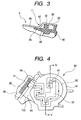
- FIG. 3 is a cross sectional view, taken along the line III - III in FIG. 2, illustrating formation of a cooling air flow path and a water shield in the automotive alternator of FIG. 1;
- FIG. 4 is a side elevational view of a seal member of the automotive alternator of FIG. 1;
- FIG. 5 is a cross sectional view, taken along the line V - V in FIG. 4, showing the internal structure of the seal member of FIG. 4; and
- FIG. 6 is a side elevational view showing the seal member and a brush assembly of the automotive alternator of FIG. 1 in the assembled state.
- The preferred embodiment of the present invention will be described hereinafter with reference to FIGS. 1 - 6.
- It should be noted that, for the sake of clarity and understanding, identical components having identical functions have been marked, where possible, with the same reference numerals in each of the figures.
- FIG. 1 shows the overall configuration of an automotive alternator (or generator) 1 according to an embodiment of the present invention.
- As shown in FIG. 1, the
automotive alternator 1 includes astator 2, arotor 3, a pair ofcooling fans 4, afront housing 5, arear housing 6, abrush assembly 7, avoltage regulator 8, arear cover 9, and apulley 10. - The
stator 2 includes a stator winding 20. Therotor 3, which includes a field winding 30, is mounted on arotary shaft 31 and surrounded by thestator 2. The coolingfans 4 are also mounted on therotary shaft 31, each of which is located close to one of the two axial ends of therotor 3, respectively. The coolingfans 4 work to create cooling air flow with rotation of therotary shaft 31. - The
front housing 5 andrear housing 6 are joined together to accommodate therein thestator 2,rotor 3, and coolingfans 4. Thefront housing 5 has a plurality ofventilation openings 50 formed therein, through which the cooling air flow created by the coolingfan 4 located in thefront housing 5 is to pass. Similarly, therear housing 6 has a plurality ofventilation openings 60 formed therein, through which the cooling air flow created by the coolingfan 4 located in therear housing 6 is to pass. Therear housing 6 also has arear wall 6a, through which anend portion 31a of therotary shaft 31 extends outside therear housing 6. - The
brush assembly 7 is composed ofbrushes brush holder 72 that accommodates thebrushes slip ring cover 73, Thebrushes brush holder 72 as to establish sliding contacts withslip rings end portion 31a of therotary shaft 31 and electrically connected with the field winding 30 of therotor 3. Thebrushes slip rings rotor 3 is rotating. Theslip ring cover 73 is provided to surround, together with thebrush holder 72, the outer periphery of the slip rings 32 and 33. - The
voltage regulator 8 is configured to regulate an output voltage of theautomotive alternator 1 to a predetermined value. - The
rear cover 9 is provided to cover thebrush assembly 7 and electrical components including thevoltage regulator 8, so as to prevent those from foreign matter. Between therear cover 9 and thebrush assembly 7, there is provided aseal member 90 that is made, for example, of rubber. - The
pulley 10 is mounted on therotary shaft 31 and works to transmit driving force from an engine (not shown) to therotary shaft 31. - Referring now to FIGS. 2 - 6, the
seal member 90 includes abase portion 91, which has the shape of a disc, and anextension portion 95 that extends radially outwardly from part of an outer circumference of thebase portion 91. - The
base portion 91 of theseal member 90 has a first end face, on whichprotrusions 92 are formed with the same protruding length so that a groove having a plurality of curves is provided between theprotrusions 92. The first end face of thebase portion 91 is brought into abutment with an inner face of a centralflat portion 96 of therear cover 9, so that a coolingair flow path 93 is formed between the first end face of thebase portion 91 and the inner face of the centralflat portion 96. The coolingair flow path 93 has the shape of a labyrinth and two opposite ends in the lengthwise direction thereof. Specifically, the radially outer end of the coolingair flow path 93 makes up anentrance 94 of the same; the radially inner end of the coolingair flow path 93 makes up anexit 81 of the same. Theexit 81 of the coolingair flow path 93 communicates with an internal space around the slip rings 32 and 33, which is surrounded by thebrush assembly 7. - The
base portion 91 of theseal member 90 has also a second end face, on which a ring-shapedgroove 80 is provided. Thegroove 80 is deformed, during assembly of theautomotive alternator 1, in a direction along which therear cover 9 is pressed against thebrush assembly 7, so that the airtightness between an end face of thebrush assembly 7 and the second end face of thebase portion 91 is secured. - The
extension portion 95 of theseal member 90 has a flat end face that connects with the first end face of thebase portion 91. On the other hand, therear cover 9 includes aflat portion 98, which is formed in the outer periphery of the centralflat portion 96, and aslope portion 97 formed between theflat portions extension portion 95 of theseal member 90 is partially brought into abutment with an inner face of theflat portion 98 of therear cover 9, thereby forming awater shield 11 that works to prevent water from entering into theentrance 94 of the coolingair flow path 93. - Specially, as shown in FIGS. 3 and 4, the
water shield 11 has anextension path 99 formed therein, which is surrounded by the end face of theextension portion 95 of theseal member 90, an inner face of theslope portion 97 of therear cover 9, the inner face of the centralflat portion 96 of therear cover 9, and side faces of theprotrusions 92 on the first end face of thebase portion 91, Theextension path 99 has an open end, which makes up anentrance 100 of theextension path 99, and a closed end. Theextension path 99 extends from the closed end to the open end across theentrance 94 of the coolingair flow path 93, so that the coolingair flow path 93 communicates with theextension path 99 at a place close to the closed end, and theentrance 100 of theextension path 99 and theentrance 94 of the coolingair flow path 93 open in different directions. Consequently, the whole cooling air flow path for supplying cooling air to thebrushes extension path 99. - To sum up, the
automotive alternator 1 according to the present embodiment includes the coolingair flow path 93, which is formed between thebase portion 91 of theseal member 90 and therear cover 9, and thewater shield 11 that is formed by theextension portion 95 of theseal member 90 and therear cover 9. - Consequently, it is possible to supply cooling air to the
brushes entrance 94 of the coolingair flow path 93 by means of thewater shield 11. - Moreover, since the
water shield 11 is obtained by utilizing part of the seal member 90 (i.e., the extension portion 95), it becomes possible to reduce the number of parts in theautomotive alternator 1 and reliably prevent water from entering into the coolingair flow path 93 from the interface between thewater shield 11 and the coolingair flow path 93. - Further, the
water shield 11 has theextension path 99 formed therein, by which the whole cooling air flow path to thebrushes brushes - Furthermore, since the
entrance 100 of theextension path 99 and theentrance 94 of the coolingair flow path 93 open in different directions, it is possible to reliably prevent water from entering into the coolingair flow path 93 even when theautomotive alternator 1 is so installed in an automobile that theentrance 94 opens in the direction of a water flow or a water drop in the automobile. Consequently, the feasible range of orientation for theautomotive alternator 1 in the automobile is increased. - In addition, since the cooling
air flow path 93 has the shape of a labyrinth, it is possible to reliably prevent foreign matter (e.g., muddy water) that has accidentally entered into the coolingair flow path 93 from reaching the inside of thebrush assembly 7. - While the above particular embodiment of the invention has been shown and described, it will be understood by those who practice the invention and those skilled in the art that various modifications, changes, and improvements may be made to the invention without departing from the spirit of the disclosed concept.
- For example, in the previous embodiment, the cooling
air flow path 93 is provided between theseal member 90 and therear cover 9. - However, the cooling
air flow path 93 may also be provided between theseal member 90 and thebrush holder 72. - Moreover, in the previous embodiment, the
water shield 11 is formed by means of theseal member 90 and therear cover 9. - However, the
water shield 11 may also be provided as an independent part without utilizing theseal member 90 and therear cover 9. - Furthermore, in the previous embodiment, the
extension portion 95 of theseal member 90 is designed to extend radially outwardly from part of the outer circumference of thebase portion 91. - However, the
extension portion 95 may also be designed to extend not only radially outwardly, but also axially toward therotor 3, from part of the outer circumference of thebase portion 91. - Such modifications, changes, and improvements within the skill of the art are intended to be covered by the appended claims.
Claims (8)
- An automotive alternator comprising:a rotary shaft having an end portion;slip rings fixed to said end portion of said rotary shaft;a brush holder;brushes accommodated in said brush holder, said brushes being so held by said brush holder as to establish sliding contacts with said slip rings to excite the automotive alternator;a cover covering said end portion of said rotary shaft, said slip rings, said brush holder, and said brushes;a seal member interposed between said brush holder and said cover;a cooling air flow path formed between said seal member and one of said brush holder and said cover to supply cooling air to said brushes; anda water shield working to prevent water from entering into an entrance of said cooling air flow path.
- The automotive alternator as set forth in Claim 1, wherein said seal member includes a base portion and an extension portion that extends radially outwardly from part of an outer circumference of said base portion, and wherein said cooling air flow path is formed between said base portion of said seal member and said cover, and said water shield is formed by said extension portion of said seal member and said cover.
- The automotive alternator as set forth in Claim 2, wherein an end face of said extension portion of said seal member is partially brought into abutment with an inner face of said cover to form said water shield.
- The automotive alternator as set forth in Claim 3, wherein said water shield has an extension path formed therein which has an open end and a closed end, and wherein said extension path extends from said closed end to said open end across said entrance of said cooling air flow path, so that said cooling air flow path communicates with said extension path at a place close to said closed end of said extension path, and said open end of said extension path and said entrance of said cooling air flow path open in different directions.
- The automotive alternator as set forth in Claim 2, wherein said base portion of said seal member has an end face on which protrusions are formed with the same protruding length so that a groove having a plurality of curves is provided between said protrusions, and wherein said end face of said base portion of said seal member is brought into abutment with an inner face of said cover to form therebetween said cooling air flow path which has the shape of a labyrinth.
- The automotive alternator as set forth in Claim 5, wherein an end face of said extension portion of said seal member is partially brought into abutment with said inner face of said cover to form said water shield.
- The automotive alternator as set forth in Claim 6, wherein said water shield has an extension path formed therein which has an open end and a closed end, and wherein said extension path extends from said closed end to said open end across said entrance of said cooling air flow path, so that said cooling air flow path communicates with said extension path at a place close to said closed end of said extension path, and said open end of said extension path and said entrance of said cooling air flow path open in different directions.
- The automotive alternator as set forth in Claim 1, wherein said cooling air flow path has the shape of a labyrinth.
Applications Claiming Priority (1)
| Application Number | Priority Date | Filing Date | Title |
|---|---|---|---|
| JP2004303807A JP4306581B2 (en) | 2004-10-19 | 2004-10-19 | Vehicle alternator |
Publications (2)
| Publication Number | Publication Date |
|---|---|
| EP1650849A1 true EP1650849A1 (en) | 2006-04-26 |
| EP1650849B1 EP1650849B1 (en) | 2010-06-09 |
Family
ID=35613797
Family Applications (1)
| Application Number | Title | Priority Date | Filing Date |
|---|---|---|---|
| EP05022721A Expired - Lifetime EP1650849B1 (en) | 2004-10-19 | 2005-10-18 | Automotive alternator having water shield for protecting brushes from water damage |
Country Status (6)
| Country | Link |
|---|---|
| US (1) | US7348700B2 (en) |
| EP (1) | EP1650849B1 (en) |
| JP (1) | JP4306581B2 (en) |
| KR (1) | KR100718662B1 (en) |
| CN (1) | CN100401622C (en) |
| DE (1) | DE602005021733D1 (en) |
Cited By (2)
| Publication number | Priority date | Publication date | Assignee | Title |
|---|---|---|---|---|
| DE102011089667A1 (en) | 2011-12-22 | 2013-06-27 | Robert Bosch Gmbh | Electrical machine of boost recuperation system for motor car, has centering sleeve that is guided in area of bearing bore of bearing plates, and is firmly connected to base portion in radial direction |
| DE102009024416B4 (en) * | 2008-06-10 | 2018-06-28 | Denso Corporation | Electric lathe |
Families Citing this family (11)
| Publication number | Priority date | Publication date | Assignee | Title |
|---|---|---|---|---|
| JP4432927B2 (en) * | 2006-04-04 | 2010-03-17 | 株式会社デンソー | Vehicle alternator |
| DE102008033681B4 (en) * | 2007-11-01 | 2022-03-24 | Denso Corporation | Vehicle alternator having a brush assembly covered with an enclosing wall |
| JP5840552B2 (en) * | 2012-03-30 | 2016-01-06 | 株式会社ミツバ | Electric motor |
| CN103560607A (en) * | 2013-11-19 | 2014-02-05 | 中电电机股份有限公司 | Sliding ring structure in winding motor with tubes arranged on periphery |
| JP6658624B2 (en) * | 2017-03-07 | 2020-03-04 | 株式会社デンソー | Rotating electric machine |
| CN108023430A (en) * | 2017-12-28 | 2018-05-11 | 索恩格汽车部件(中国)有限公司 | For the protection cap of AC generator for vehicle carbon brush system, alternating current generator and automobile |
| DE102018117499A1 (en) * | 2018-07-19 | 2020-01-23 | Seg Automotive Germany Gmbh | Electrical machine |
| CN111384810B (en) * | 2018-12-28 | 2022-11-11 | 日本电产(大连)有限公司 | Brush motor and electrical equipment |
| CN114243989B (en) * | 2021-12-24 | 2023-08-11 | 成都华川电装有限责任公司 | Brush holder structure for AC generator |
| CN116937861B (en) * | 2023-07-13 | 2024-08-30 | 常州宝马前杨电机电器有限公司 | Waterproof permanent magnet three-phase alternating current servo motor |
| FR3155665A1 (en) * | 2023-11-22 | 2025-05-23 | Ampere | Electrically excited electric machine equipped with a cooling device |
Citations (9)
| Publication number | Priority date | Publication date | Assignee | Title |
|---|---|---|---|---|
| US3731126A (en) * | 1970-10-12 | 1973-05-01 | Bosch Gmbh Robert | Electrical machine with shielded circuit parts |
| US4939397A (en) * | 1989-10-05 | 1990-07-03 | Morrill Giles W | Spray-resistant electric motor |
| US4959576A (en) * | 1987-11-25 | 1990-09-25 | Nippondenso Co., Ltd. | Automotive alternator |
| US5424600A (en) * | 1991-11-06 | 1995-06-13 | Nippondenso Co., Ltd. | Spark protected alternator |
| US6060802A (en) * | 1997-09-25 | 2000-05-09 | Denso Corporation | AC generator for an automotive vehicle |
| US20020047470A1 (en) * | 2000-08-11 | 2002-04-25 | Denso Corporation | Rotary electric machine |
| US20020047465A1 (en) * | 2000-04-27 | 2002-04-25 | Seung-Il Chang | Structure for preventing flame of alternator for vehicle |
| JP2002345198A (en) * | 2001-05-11 | 2002-11-29 | Denso Corp | AC generator for vehicles |
| US6515398B1 (en) * | 1999-02-04 | 2003-02-04 | Denso Corporation | Alternator having passage for ventilating slip-ring surface |
Family Cites Families (10)
| Publication number | Priority date | Publication date | Assignee | Title |
|---|---|---|---|---|
| JPS5851663A (en) | 1981-09-24 | 1983-03-26 | Fujitsu Ltd | Trunk system for switchboard |
| JPH0732571B2 (en) | 1988-04-26 | 1995-04-10 | 日本電装株式会社 | AC generator manufacturing method |
| KR950022277U (en) * | 1993-12-29 | 1995-07-28 | Panel structure with fixing hole to fix wiring arrangement | |
| WO1998054822A1 (en) * | 1997-05-26 | 1998-12-03 | Denso Corporation | Ac generator for vehicle |
| JP3911879B2 (en) * | 1998-11-02 | 2007-05-09 | 株式会社デンソー | AC generator for vehicles |
| JP2002101613A (en) * | 2000-09-21 | 2002-04-05 | Denso Corp | Alternator |
| US6727625B2 (en) * | 2000-09-25 | 2004-04-27 | Denso Corporation | Rotary electric machine and method for manufacturing the same |
| JP3905300B2 (en) * | 2000-10-30 | 2007-04-18 | 三菱電機株式会社 | AC generator for vehicles |
| JP3750851B2 (en) * | 2002-01-18 | 2006-03-01 | 株式会社デンソー | AC generator for vehicles |
| JP2004320906A (en) * | 2003-04-17 | 2004-11-11 | Denso Corp | AC generator for vehicles |
-
2004
- 2004-10-19 JP JP2004303807A patent/JP4306581B2/en not_active Expired - Fee Related
-
2005
- 2005-10-18 EP EP05022721A patent/EP1650849B1/en not_active Expired - Lifetime
- 2005-10-18 KR KR1020050098206A patent/KR100718662B1/en not_active Expired - Fee Related
- 2005-10-18 DE DE602005021733T patent/DE602005021733D1/en not_active Expired - Lifetime
- 2005-10-19 CN CNB2005101140202A patent/CN100401622C/en not_active Expired - Fee Related
- 2005-10-19 US US11/252,787 patent/US7348700B2/en not_active Expired - Fee Related
Patent Citations (9)
| Publication number | Priority date | Publication date | Assignee | Title |
|---|---|---|---|---|
| US3731126A (en) * | 1970-10-12 | 1973-05-01 | Bosch Gmbh Robert | Electrical machine with shielded circuit parts |
| US4959576A (en) * | 1987-11-25 | 1990-09-25 | Nippondenso Co., Ltd. | Automotive alternator |
| US4939397A (en) * | 1989-10-05 | 1990-07-03 | Morrill Giles W | Spray-resistant electric motor |
| US5424600A (en) * | 1991-11-06 | 1995-06-13 | Nippondenso Co., Ltd. | Spark protected alternator |
| US6060802A (en) * | 1997-09-25 | 2000-05-09 | Denso Corporation | AC generator for an automotive vehicle |
| US6515398B1 (en) * | 1999-02-04 | 2003-02-04 | Denso Corporation | Alternator having passage for ventilating slip-ring surface |
| US20020047465A1 (en) * | 2000-04-27 | 2002-04-25 | Seung-Il Chang | Structure for preventing flame of alternator for vehicle |
| US20020047470A1 (en) * | 2000-08-11 | 2002-04-25 | Denso Corporation | Rotary electric machine |
| JP2002345198A (en) * | 2001-05-11 | 2002-11-29 | Denso Corp | AC generator for vehicles |
Non-Patent Citations (1)
| Title |
|---|
| PATENT ABSTRACTS OF JAPAN vol. 2003, no. 03 5 May 2003 (2003-05-05) * |
Cited By (2)
| Publication number | Priority date | Publication date | Assignee | Title |
|---|---|---|---|---|
| DE102009024416B4 (en) * | 2008-06-10 | 2018-06-28 | Denso Corporation | Electric lathe |
| DE102011089667A1 (en) | 2011-12-22 | 2013-06-27 | Robert Bosch Gmbh | Electrical machine of boost recuperation system for motor car, has centering sleeve that is guided in area of bearing bore of bearing plates, and is firmly connected to base portion in radial direction |
Also Published As
| Publication number | Publication date |
|---|---|
| KR100718662B1 (en) | 2007-05-15 |
| CN1767330A (en) | 2006-05-03 |
| DE602005021733D1 (en) | 2010-07-22 |
| EP1650849B1 (en) | 2010-06-09 |
| JP4306581B2 (en) | 2009-08-05 |
| US20060082233A1 (en) | 2006-04-20 |
| US7348700B2 (en) | 2008-03-25 |
| JP2006121767A (en) | 2006-05-11 |
| CN100401622C (en) | 2008-07-09 |
| KR20060054087A (en) | 2006-05-22 |
Similar Documents
| Publication | Publication Date | Title |
|---|---|---|
| US7417353B2 (en) | On-vehicle alternator with brush/slip ring structure | |
| US7348700B2 (en) | Automotive alternator having water shield for protecting brushes from water damage | |
| US8193682B2 (en) | Vehicle alternator provided with brushes, brush holder, and slip rings | |
| US5550418A (en) | Alternator for use in an automobile | |
| KR100454691B1 (en) | AC generator for a vehicle | |
| US7579741B2 (en) | Automotive dynamoelectric machine | |
| US6900566B2 (en) | Vehicle AC generator | |
| US7531927B2 (en) | Vehicle-use AC generator having rear cover formed to prevent intrusion of foreign matter into vicinity of slip rings | |
| EP1608051B1 (en) | Alternator having a slip-ring cover connected to brush holder | |
| US20070170821A1 (en) | Brushless automotive alternator having improved structure for minimizing temperature of auxiliary rectifying elements | |
| JP4333754B2 (en) | Vehicle alternator | |
| CN107996016B (en) | Vehicle Rotary Electric Machine | |
| JP3785964B2 (en) | AC generator for vehicles | |
| JP4609445B2 (en) | AC generator for vehicles | |
| JP4412152B2 (en) | Vehicle alternator | |
| JP2002315283A (en) | Electric rotating machine for vehicles | |
| JP2002119009A (en) | Electric rotating machine for vehicles | |
| US20090115274A1 (en) | Automotive alternator having brush device covered with surrounding wall | |
| JP4306767B2 (en) | Vehicle alternator |
Legal Events
| Date | Code | Title | Description |
|---|---|---|---|
| PUAI | Public reference made under article 153(3) epc to a published international application that has entered the european phase |
Free format text: ORIGINAL CODE: 0009012 |
|
| AK | Designated contracting states |
Kind code of ref document: A1 Designated state(s): AT BE BG CH CY CZ DE DK EE ES FI FR GB GR HU IE IS IT LI LT LU LV MC NL PL PT RO SE SI SK TR |
|
| AX | Request for extension of the european patent |
Extension state: AL BA HR MK YU |
|
| 17P | Request for examination filed |
Effective date: 20060704 |
|
| AKX | Designation fees paid |
Designated state(s): DE FR GB |
|
| 17Q | First examination report despatched |
Effective date: 20071017 |
|
| GRAP | Despatch of communication of intention to grant a patent |
Free format text: ORIGINAL CODE: EPIDOSNIGR1 |
|
| RAP1 | Party data changed (applicant data changed or rights of an application transferred) |
Owner name: DENSO CORPORATION |
|
| GRAS | Grant fee paid |
Free format text: ORIGINAL CODE: EPIDOSNIGR3 |
|
| GRAA | (expected) grant |
Free format text: ORIGINAL CODE: 0009210 |
|
| AK | Designated contracting states |
Kind code of ref document: B1 Designated state(s): DE FR GB |
|
| REF | Corresponds to: |
Ref document number: 602005021733 Country of ref document: DE Date of ref document: 20100722 Kind code of ref document: P |
|
| REG | Reference to a national code |
Ref country code: GB Ref legal event code: 746 Effective date: 20101130 |
|
| PLBE | No opposition filed within time limit |
Free format text: ORIGINAL CODE: 0009261 |
|
| STAA | Information on the status of an ep patent application or granted ep patent |
Free format text: STATUS: NO OPPOSITION FILED WITHIN TIME LIMIT |
|
| 26N | No opposition filed |
Effective date: 20110310 |
|
| REG | Reference to a national code |
Ref country code: DE Ref legal event code: R097 Ref document number: 602005021733 Country of ref document: DE Effective date: 20110309 |
|
| PGFP | Annual fee paid to national office [announced via postgrant information from national office to epo] |
Ref country code: GB Payment date: 20131021 Year of fee payment: 9 Ref country code: DE Payment date: 20131021 Year of fee payment: 9 Ref country code: FR Payment date: 20131022 Year of fee payment: 9 |
|
| REG | Reference to a national code |
Ref country code: DE Ref legal event code: R119 Ref document number: 602005021733 Country of ref document: DE |
|
| GBPC | Gb: european patent ceased through non-payment of renewal fee |
Effective date: 20141018 |
|
| PG25 | Lapsed in a contracting state [announced via postgrant information from national office to epo] |
Ref country code: DE Free format text: LAPSE BECAUSE OF NON-PAYMENT OF DUE FEES Effective date: 20150501 Ref country code: GB Free format text: LAPSE BECAUSE OF NON-PAYMENT OF DUE FEES Effective date: 20141018 |
|
| REG | Reference to a national code |
Ref country code: FR Ref legal event code: ST Effective date: 20150630 |
|
| PG25 | Lapsed in a contracting state [announced via postgrant information from national office to epo] |
Ref country code: FR Free format text: LAPSE BECAUSE OF NON-PAYMENT OF DUE FEES Effective date: 20141031 |