EP1650498B1 - Safety cut-off for pressurized water vapour producing devices - Google Patents
Safety cut-off for pressurized water vapour producing devices Download PDFInfo
- Publication number
- EP1650498B1 EP1650498B1 EP05256603.1A EP05256603A EP1650498B1 EP 1650498 B1 EP1650498 B1 EP 1650498B1 EP 05256603 A EP05256603 A EP 05256603A EP 1650498 B1 EP1650498 B1 EP 1650498B1
- Authority
- EP
- European Patent Office
- Prior art keywords
- valve
- lever
- cam
- water
- safety cut
- Prior art date
- Legal status (The legal status is an assumption and is not a legal conclusion. Google has not performed a legal analysis and makes no representation as to the accuracy of the status listed.)
- Not-in-force
Links
Images


Classifications
-
- F—MECHANICAL ENGINEERING; LIGHTING; HEATING; WEAPONS; BLASTING
- F22—STEAM GENERATION
- F22B—METHODS OF STEAM GENERATION; STEAM BOILERS
- F22B1/00—Methods of steam generation characterised by form of heating method
- F22B1/28—Methods of steam generation characterised by form of heating method in boilers heated electrically
- F22B1/284—Methods of steam generation characterised by form of heating method in boilers heated electrically with water in reservoirs
Definitions
- the present invention relates to a safety cut-off for any type of device, preferably for domestic use, which is designed to produce pressurised vapour for different purposes.
- the present invention relates to a safety cut-off for any type of device which is designed to produce pressurised steam for different purposes, such as to avoid the risk of accidents by scalding when filling with water, and when pressurised steam exists in the steam chamber.
- EP0662298 refers to a safety water reservoir seal for coffee makers having a valve working with a first spring which biases an open seal position and the a second spring biasing a closed seal position and associated to a lever drivable against its spring.
- the lever is driven by a cam associated a cover. When the cover is swivelled sideways the lever is made to swivel, thereby freeing the one-way valve seal.
- GB2048426 discloses a locking device for pressure-cooker lids for preventing the opening when there is internal pressure. It has a lid with a supporting crossbar the ends of which rest on the edge of the container opening, and a lever pivoted to the lid and capable of moving between an opening position and a closing position. In the closing position a cam-shaped portion of the lever acts against the crossbar causing the peripheral edge of the lid to press against a sealing.
- the lever has an apertured portion designed for engaging a locking pin operated by internal pressure, the pin being provided in the lid for engaging the portion when the lever is in its lowered position.
- the present invention proposes a safety cut-off for pressurised water vapour producing devices for domestic use, which complies with a particular composition consisting of a folding top which is disposed in closing/opening relationship with the access to a funnel through which the water must be poured for filling and refilling of the boiler in which the steam is produced, which top has a top shaft in relation with which there rotates a cam which is integral with the top, and which has an active periphery which is applied to a camshaft which is incorporated in a lever which can rotate relative to a lever shaft, and which, spaced from the latter, has an aperture through which there slides vertically a rod, which at its lower end incorporates a filling valve which is interposed between the funnel and a chamber for output of the steam produced in the boiler, which filling valve can adopt two, upper and lower operative positions such that, in the upper position, the filling valve acts as a shutter seat on the lower plane of a valve passage which puts the funnel into communication with the output chamber, and, in the
- This arrangement ensures that, when the top is raised and pressurised steam exists in the steam chamber, the valve for filling and closure will remain closed, thus preventing steam from escaping and scalding the user.
- This closure arrangement provides functionality which ensures prevention of the above-described risk of accidents.
- the combined configuration of a folding top cam and lever camshaft means that, when the top is open, the lower position of the lever is forced against the spring which impels its upper position, such that the action of the helical spring, which impels the lower position of the water filling valve, together with the weight of the filling valve itself, means that the filling valve effectively occupies this lower position which permits passage of water to the boiler through the valve passage.
- the position in which the folding top is closed gives rise to relaxing of the spring, which, when it recovers resiliently, leads to raising of the rod, and thus of the filling valve, by means of the action of the aperture in the lever on the flange of the rod, which takes place by means of compression of the helical spring, and provides the position of closure of the water filling valve.
- the filling valve is closed, the pressure of the water vapour generated in the boiler maintains this situation of closure even if someone opens the top to carry out refilling, without realising that there is pressurised water vapour in the device. This means that the top can be opened in any circumstance without any danger of the pressurised water being able to be projected towards the user, who remains protected against the risk of accidental scalding.
- the lower position of the lever is compatible with the upper position (of closure) of the valve for filling with water and closure, since the rod of the latter passes freely through its aperture, and it is only when the rod and lever are in their lower positions that the raising of the lever also draws the rod such that its flange cannot pass through the aperture in the lever, as previously described.
- Another advantageous feature of the invention consists in the ease and convenience of access which, for the filling with water, presupposes the action of opening/closure of a folding top, compared with the unscrewing and subsequent re-screwing of a stopper which requires many turns in order to provide safe and efficient closure.
- another feature of the invention is that on its free edge the top has a thumb grip which facilitates its handling.
- Another feature of the invention is that, in parallel with the filling valve, there exists a safety valve which is interposed between the funnel and the output chamber.
- the rod at its upper end, is extended by means of an extension which at its tip incorporates an ostentatious colour, and is guided in a hole which communicates with the funnel as closed by the top, and, with reference to the position of opening, or the lower position, and the position of closure, or the upper position, of the valve for filling with water and closure, the extension occupies respective lower and upper positions, such that, in the lower position, its coloured tip is retracted in the hole, whereas, in the upper position, the tip penetrates in a cavity which is formed in a transparent cover located in the funnel.
- the safety cut-off includes a plate interposed between the valve passage and the lever, the size of the periphery of which is designed to leave a channel of communication with the funnel, which, although narrow, allows water to access the steam chamber.
- This solution is specifically designed to prevent steam produced spontaneously when filling the device with cold water, as a result of the steam chamber still being hot from recent previous use, from being able to escape to the exterior and be projected onto the user, and provides that the generated steam will startle the user but not injure him, unlike the previous situation, which is now avoided.
- Figure 1 shows in cross-section a device for producing pressurised water vapour for domestic use, which is provided with a folding top, in accordance with a first embodiment of the present invention.
- This Figure incorporates an enlarged detail of the device, in the position in which the top is open.
- Figure 2 is the same view as Figure 1 , but relates to the closed position of the top.
- Figure 3 is the same view as Figure 2 , but with the top open when there is water vapour pressure in the boiler.
- Figure 4 is a similar view to that of Figure 1 , and represents the situation of functioning in the case of a pressurised water vapour spray gun, illustrating the action of firing, as can be seen clearly in the enlarged detail incorporated in this Figure.
- Figure 5 shows in cross-section a device for producing pressurised water vapour for domestic use, which is provided with a folding top, in accordance with a second embodiment of the present invention.
- Figure 6 is the same view as Figure 5 , but relates to the position in which the top is closed and pressure exists in the steam chamber.
- Figure 7 is the same view as Figure 5 , but relates to the position in which the top is open and pressure exists in the steam chamber.
- the purpose of the invention is to avoid scalding and other possible damage which can be caused by the devices known hitherto in this field, when the user inadvertently proceeds to fill the boiler with water, without realising that the device is functioning and contains pressurised water vapour in its interior.
- the existing arrangement which provides for closure by means of a threaded stopper, does not provide for safety of the user, since, when the stopper is loosened, pressurised water vapour begins to rise towards the user, or the stopper can even rise and be launched as if it were a projectile.
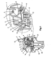
- Figures 1 to 4 illustrate a device in accordance with a first embodiment of the present invention.
- the safety cut-off comprises a folding top 1 which is disposed in closing/opening relationship at the access to a funnel 2, through which water is poured for filling and refilling of the boiler in which the steam is produced.
- the top 1 has a top shaft 3, in relation to which there rotates a cam 4 which is integral with the top 1 and which has an active periphery which is applied to a cam surface 6 which is incorporated in a lever 5, which can rotate relative to a lever shaft 7, and which, spaced from the latter, has an aperture 8 through which there slides vertically a rod 10, which at its lower end incorporates a valve 9 for filling and closure, which is Interposed between the funnel 2 and a chamber 12 for the steam produced in the boiler.
- the valve 9 for filling and closure can adopt one of two, upper and lower, operative positions, such that, in the upper position, the valve 9 for filling and closure acts as a shutter seat on the lower plane of a valve passage 11 which puts the funnel 2 out of communication with the steam chamber 12, and, in the lower position, the valve 9 for filling and closure is separated from the seat.
- the lever 5 has a torsion spring 13 associated therewith, such that the lever 5 can oscillate between two, upper and lower, operative positions, such that, in the lower position, the torsion spring 13 is in its state of greatest relative tension, and the contact between the cam surface 6 of the lever 5 and the cam 4 of the top 1 takes place on a part of the cam 4 with a larger radius than that which is provided by the open position of the top 1, and, in the upper position, the torsion spring 13 is in its state of greatest relative relaxation, and the contact between the cam surface 6 and cam 4 takes place on a part of the cam 4 with a smaller radius than that which is provided by the closed position of the top 1.
- the rod 10 passes through the aperture 8 in the lever 5, and projects from an end part on which there exists a flange 14 which has a size larger than the diameter of the aperture 8, and on which there is supported the lower end of a helical compression spring 15, which is weaker than the torsion spring 13 which is associated with the lever 5, and which impels the filling and closure valve 9 to a lower position, in which the flange 14 remains against the aperture 8 and the lever 5 occupies its lower position.
- FIGs 1 to 3 illustrate the functionality of the device.
- the folding top 1 is open, and there is no steam pressure in the boiler.
- the lever 5 occupies its lower position against the resilient action of the torsion spring 13, which in turn means that, by means of the action of the helical spring 15 and its own weight, the valve 9 occupies its lower position which is delimited by the abutment of the flange 14 of the rod 10 against the aperture 8 of the lever 5, which leaves the valve passage 11 free for filling the boiler with water.
- FIG. 2 illustrates the folding top 1
- this conjugated configuration of the cam 4 and cam surface 6 removes the pressure on the torsion spring 13, and its resilient recovery gives rise to transfer of the lever 5 to its upper position, drawing with it the rod 10 because of the action of the aperture 8 on the flange 14 of the latter.
- Figure 3 illustrates the safety function wherein the folding top 1 can be opened without danger, since the pressure of the water vapour ensures the closure of the valve 9, providing a greatly reduced vapour pressure, which in all cases is insufficient to cause any damage to the user.
- Another feature of the present invention is a safety valve 17 which, in parallel to the valve 9, is interposed between the funnel 2 and the vapour chamber 12.
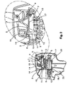
- Figure 4 illustrates the actuation in spraying of the pressurised water vapour as generated, where the device for this purpose is of the gun type.
- the trigger 18 when the trigger 18 is pressed, the trigger 18 acts on a thruster 19 which acts on the steam output valve shaft 20, separating the latter from its closure seat 21, and thus enabling the release of the pressurised water vapour.
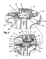
- FIGS 5 to 7 illustrate a device in accordance with a second embodiment of the present invention.
- the rod 10 is extended by means of an extension 10.1, which at its tip has an ostentatious colour, and is guided in a hole 24 which communicates with the funnel 2 as closed by the top 1.
- the extension 10.1 occupies respective lower and upper positions, such that, in the lower position, the coloured tip is retracted In the hole 24, whereas, in the upper position, the coloured tip penetrates in a cavity 25.1 which is formed in a transparent cover 25 located in the funnel 2.
- Figures 5 to 7 illustrate the different functioning situations.
- Figure 5 shows the state in which the steam chamber 12 is without steam and cold, where the device is ready to be filled with water in order to begin operation. It can be seen that the extension 10.1 of the rod 10 is retracted in the hole 24 and its coloured tip cannot be seen through the transparent cover 25 which acts as a viewer.
- the top 1 is closed, and when the equipment is connected up to the mains supply, the steam pressure begins to be sufficient, as illustrated in Figure 6 , and the extension 10.1 of the rod 10 slides through the hole 24, such that the coloured tip penetrates into the cavity 25.1 in the viewer as constituted by the transparent cover 25.
- valve passage 11 there is interposed a plate 26, the size of the periphery of which is designed to leave a channel of communication with the funnel 2, which, although narrow, allows water to access the steam chamber 12.
- this device makes it possible to prevent the steam from being projected dangerously towards the user when the steam chamber 12 is filled with cold water when it is open and empty, but still hot from recent use.
Landscapes
- Engineering & Computer Science (AREA)
- Life Sciences & Earth Sciences (AREA)
- Sustainable Development (AREA)
- Sustainable Energy (AREA)
- Physics & Mathematics (AREA)
- Thermal Sciences (AREA)
- Mechanical Engineering (AREA)
- General Engineering & Computer Science (AREA)
- Mechanically-Actuated Valves (AREA)
- Cookers (AREA)
- Safety Valves (AREA)
Description
- The present invention relates to a safety cut-off for any type of device, preferably for domestic use, which is designed to produce pressurised vapour for different purposes. In particular, the present invention relates to a safety cut-off for any type of device which is designed to produce pressurised steam for different purposes, such as to avoid the risk of accidents by scalding when filling with water, and when pressurised steam exists in the steam chamber.
- In the field of this invention, at present, there exist devices wherein access to fill and refill the boiler, in which the pressurised vapour is produced, with water is by means of a screw stopper in which a safety valve is incorporated.
- This arrangement has various disadvantages. The most significant, in terms of the risk which it involves for the physical safety of people, is in the danger of accidental scalding which the user may sustain when refilling the device with water, if the person concerned is not aware that the device is functioning and contains pressurised water vapour which will be projected towards the user when the stopper is removed, or is simply loosened. Indeed, the stopper itself may even be projected against the user, as if it were a projectile. Another disadvantage is in the fact that in order to guarantee efficient closure, the stopper has a fine screw thread which needs numerous turns in order to be screwed on and unscrewed. This is inconvenient and impractical.
-
EP0662298 refers to a safety water reservoir seal for coffee makers having a valve working with a first spring which biases an open seal position and the a second spring biasing a closed seal position and associated to a lever drivable against its spring. The lever is driven by a cam associated a cover. When the cover is swivelled sideways the lever is made to swivel, thereby freeing the one-way valve seal. -
GB2048426 - In one aspect the present invention proposes a safety cut-off for pressurised water vapour producing devices for domestic use, which complies with a particular composition consisting of a folding top which is disposed in closing/opening relationship with the access to a funnel through which the water must be poured for filling and refilling of the boiler in which the steam is produced, which top has a top shaft in relation with which there rotates a cam which is integral with the top, and which has an active periphery which is applied to a camshaft which is incorporated in a lever which can rotate relative to a lever shaft, and which, spaced from the latter, has an aperture through which there slides vertically a rod, which at its lower end incorporates a filling valve which is interposed between the funnel and a chamber for output of the steam produced in the boiler, which filling valve can adopt two, upper and lower operative positions such that, in the upper position, the filling valve acts as a shutter seat on the lower plane of a valve passage which puts the funnel into communication with the output chamber, and, in the lower position, the filling valve is separated from the shutter seat, the lever of which has a spring associated with it, and can oscillate between two, upper and lower operative positions, such that, in the lower position, the spring is in its state of greatest relative tension, and the contact between the camshaft of the lever and the cam of the top takes place on a part of the cam with a larger radius than that which is provided by the open position of the top, and in the upper position, the spring is in its state of greatest relative relaxation, and the contact between the camshaft and cam takes place on a part of the cam with a smaller radius than that which is provided by the closed position of the top, and, in the upper part of the valve passage, the rod passes through the aperture in the lever, and projects from an outer part on which there exists a flange which has a size larger than the diameter of the aperture, and on which there is supported the lower end of a helical compression spring which is weaker than the spring which is associated with the lever, and which impels the valve to the open position in which the flange remains against the aperture and the lever occupies its lower position.
- This arrangement ensures that, when the top is raised and pressurised steam exists in the steam chamber, the valve for filling and closure will remain closed, thus preventing steam from escaping and scalding the user.
- This closure arrangement provides functionality which ensures prevention of the above-described risk of accidents. In fact, the combined configuration of a folding top cam and lever camshaft means that, when the top is open, the lower position of the lever is forced against the spring which impels its upper position, such that the action of the helical spring, which impels the lower position of the water filling valve, together with the weight of the filling valve itself, means that the filling valve effectively occupies this lower position which permits passage of water to the boiler through the valve passage. On the other hand, the position in which the folding top is closed gives rise to relaxing of the spring, which, when it recovers resiliently, leads to raising of the rod, and thus of the filling valve, by means of the action of the aperture in the lever on the flange of the rod, which takes place by means of compression of the helical spring, and provides the position of closure of the water filling valve. When the filling valve is closed, the pressure of the water vapour generated in the boiler maintains this situation of closure even if someone opens the top to carry out refilling, without realising that there is pressurised water vapour in the device. This means that the top can be opened in any circumstance without any danger of the pressurised water being able to be projected towards the user, who remains protected against the risk of accidental scalding. In this situation, the lower position of the lever is compatible with the upper position (of closure) of the valve for filling with water and closure, since the rod of the latter passes freely through its aperture, and it is only when the rod and lever are in their lower positions that the raising of the lever also draws the rod such that its flange cannot pass through the aperture in the lever, as previously described.
- Another advantageous feature of the invention consists in the ease and convenience of access which, for the filling with water, presupposes the action of opening/closure of a folding top, compared with the unscrewing and subsequent re-screwing of a stopper which requires many turns in order to provide safe and efficient closure. In this respect, and for greater convenience, another feature of the invention is that on its free edge the top has a thumb grip which facilitates its handling.
- Another feature of the invention is that, in parallel with the filling valve, there exists a safety valve which is interposed between the funnel and the output chamber.
- In another advantageous embodiment the rod, at its upper end, is extended by means of an extension which at its tip incorporates an ostentatious colour, and is guided in a hole which communicates with the funnel as closed by the top, and, with reference to the position of opening, or the lower position, and the position of closure, or the upper position, of the valve for filling with water and closure, the extension occupies respective lower and upper positions, such that, in the lower position, its coloured tip is retracted in the hole, whereas, in the upper position, the tip penetrates in a cavity which is formed in a transparent cover located in the funnel.
- The functioning of this solution is apparent. When there is insufficient pressure in the steam chamber for the valve for filling and closure to be closed, the valve will be open, and thus, the extension of the rod will be retracted and its coloured tip will not be seen through the viewer constituted by the transparent cover located in the funnel of the device. On the other hand, when steam pressure in excess of the safety limit exists, the valve will be closed, and the ostentatious coloured tip of the rod will have penetrated into the cavity in the viewer, and, when the top is raised, it will be clearly visible by the user, and will indicate to the latter that it is not yet possible to proceed to refill the steam chamber with water.
- Another feature of the present invention is that the safety cut-off includes a plate interposed between the valve passage and the lever, the size of the periphery of which is designed to leave a channel of communication with the funnel, which, although narrow, allows water to access the steam chamber.
- This solution is specifically designed to prevent steam produced spontaneously when filling the device with cold water, as a result of the steam chamber still being hot from recent previous use, from being able to escape to the exterior and be projected onto the user, and provides that the generated steam will startle the user but not injure him, unlike the previous situation, which is now avoided.
- These and other features of the invention are made apparent in the following graphic description.
- In order to understand better the nature of the present invention, the attached drawings represent a preferred form of an industrial embodiment, the nature of which is purely illustrative and non-limiting.
-
Figure 1 shows in cross-section a device for producing pressurised water vapour for domestic use, which is provided with a folding top, in accordance with a first embodiment of the present invention. This Figure incorporates an enlarged detail of the device, in the position in which the top is open. -
Figure 2 is the same view asFigure 1 , but relates to the closed position of the top. -
Figure 3 is the same view asFigure 2 , but with the top open when there is water vapour pressure in the boiler. -
Figure 4 is a similar view to that ofFigure 1 , and represents the situation of functioning in the case of a pressurised water vapour spray gun, illustrating the action of firing, as can be seen clearly in the enlarged detail incorporated in this Figure. -
Figure 5 shows in cross-section a device for producing pressurised water vapour for domestic use, which is provided with a folding top, in accordance with a second embodiment of the present invention. -
Figure 6 is the same view asFigure 5 , but relates to the position in which the top is closed and pressure exists in the steam chamber. -
Figure 7 is the same view asFigure 5 , but relates to the position in which the top is open and pressure exists in the steam chamber. -
- 1.
- Folding top
- 2.
- Funnel
- 3.
- Top (1) shaft
- 4.
- Top (1) cam
- 5.
- Lever
- 6.
- Lever (5) camshaft
- 7.
- Lever (5) shaft
- 8.
- Lever (5) aperture
- 9.
- Water filling and closure valve
- 10.
- Water filling and closure valve (9) rod
- 11.
- Valve passage
- 12.
- Steam chamber
- 13.
- Torsion spring
- 14.
- Rod (10) flange
- 15.
- Helical compression spring
- 16.
- Thumb/Finger grip
- 17.
- Safety valve
- 18.
- Trigger
- 19.
- Trigger thruster
- 20.
- Steam output valve shaft
- 21.
- Closure seat for steam output valve shaft (20)
- 22.
- Water retention seal
- 23.
- Support for the safety cut-off
- 10.1.
- Rod (10) extension
- 24.
- Viewer hole which communicates with the funnel (2)
- 25.
- Funnel (2) transparent cover or viewer
- 25.1.
- Transparent cover (25) cavity
- 26.
- Plate between valve passage (11) and lever (5)
- With reference to the drawings and references listed above, the accompanying drawings illustrate preferred embodiments of the present invention, relating to a safety cut-off for devices for production of pressurised water vapour, in particular for domestic use.
- The purpose of the invention is to avoid scalding and other possible damage which can be caused by the devices known hitherto in this field, when the user inadvertently proceeds to fill the boiler with water, without realising that the device is functioning and contains pressurised water vapour in its interior.
- In such cases, the existing arrangement, which provides for closure by means of a threaded stopper, does not provide for safety of the user, since, when the stopper is loosened, pressurised water vapour begins to rise towards the user, or the stopper can even rise and be launched as if it were a projectile.
-
Figures 1 to 4 illustrate a device in accordance with a first embodiment of the present invention. - The safety cut-off comprises a folding top 1 which is disposed in closing/opening relationship at the access to a
funnel 2, through which water is poured for filling and refilling of the boiler in which the steam is produced. - The top 1 has a
top shaft 3, in relation to which there rotates acam 4 which is integral with the top 1 and which has an active periphery which is applied to acam surface 6 which is incorporated in alever 5, which can rotate relative to alever shaft 7, and which, spaced from the latter, has anaperture 8 through which there slides vertically arod 10, which at its lower end incorporates avalve 9 for filling and closure, which is Interposed between thefunnel 2 and achamber 12 for the steam produced in the boiler. - The
valve 9 for filling and closure can adopt one of two, upper and lower, operative positions, such that, in the upper position, thevalve 9 for filling and closure acts as a shutter seat on the lower plane of avalve passage 11 which puts thefunnel 2 out of communication with thesteam chamber 12, and, in the lower position, thevalve 9 for filling and closure is separated from the seat. - The
lever 5 has atorsion spring 13 associated therewith, such that thelever 5 can oscillate between two, upper and lower, operative positions, such that, in the lower position, thetorsion spring 13 is in its state of greatest relative tension, and the contact between thecam surface 6 of thelever 5 and thecam 4 of the top 1 takes place on a part of thecam 4 with a larger radius than that which is provided by the open position of the top 1, and, in the upper position, thetorsion spring 13 is in its state of greatest relative relaxation, and the contact between thecam surface 6 andcam 4 takes place on a part of thecam 4 with a smaller radius than that which is provided by the closed position of the top 1. - In the upper part of the
valve passage 11, therod 10 passes through theaperture 8 in thelever 5, and projects from an end part on which there exists aflange 14 which has a size larger than the diameter of theaperture 8, and on which there is supported the lower end of ahelical compression spring 15, which is weaker than thetorsion spring 13 which is associated with thelever 5, and which impels the filling andclosure valve 9 to a lower position, in which theflange 14 remains against theaperture 8 and thelever 5 occupies its lower position. -
Figures 1 to 3 illustrate the functionality of the device. InFigure 1 , thefolding top 1 is open, and there is no steam pressure in the boiler. In this case, for the conjugated configuration of thecam 4 and thecam surface 6, thelever 5 occupies its lower position against the resilient action of thetorsion spring 13, which in turn means that, by means of the action of thehelical spring 15 and its own weight, thevalve 9 occupies its lower position which is delimited by the abutment of theflange 14 of therod 10 against theaperture 8 of thelever 5, which leaves thevalve passage 11 free for filling the boiler with water. When the folding top 1 is closed, as illustrated inFigure 2 , this conjugated configuration of thecam 4 andcam surface 6 removes the pressure on thetorsion spring 13, and its resilient recovery gives rise to transfer of thelever 5 to its upper position, drawing with it therod 10 because of the action of theaperture 8 on theflange 14 of the latter.Figure 3 illustrates the safety function wherein the folding top 1 can be opened without danger, since the pressure of the water vapour ensures the closure of thevalve 9, providing a greatly reduced vapour pressure, which in all cases is insufficient to cause any damage to the user. - The use itself of a folding top 1, instead of the present screw stopper, provides for considerable ease and convenience of handling, which is further increased by the fact that, on its free edge, the top 1 has a thumb/
finger grip 16 as can be seen inFigures 1 to 4 . - Another feature of the present invention is a
safety valve 17 which, in parallel to thevalve 9, is interposed between thefunnel 2 and thevapour chamber 12. -
Figure 4 illustrates the actuation in spraying of the pressurised water vapour as generated, where the device for this purpose is of the gun type. In this case, when thetrigger 18 is pressed, thetrigger 18 acts on athruster 19 which acts on the steamoutput valve shaft 20, separating the latter from itsclosure seat 21, and thus enabling the release of the pressurised water vapour. -
Figures 5 to 7 illustrate a device in accordance with a second embodiment of the present invention. - As shown in
Figure 5 , at its upper end, therod 10 is extended by means of an extension 10.1, which at its tip has an ostentatious colour, and is guided in ahole 24 which communicates with thefunnel 2 as closed by the top 1. With reference to the open or lower position and the closed or upper position of thevalve 9, the extension 10.1 occupies respective lower and upper positions, such that, in the lower position, the coloured tip is retracted In thehole 24, whereas, in the upper position, the coloured tip penetrates in a cavity 25.1 which is formed in atransparent cover 25 located in thefunnel 2. -
Figures 5 to 7 illustrate the different functioning situations.Figure 5 shows the state in which thesteam chamber 12 is without steam and cold, where the device is ready to be filled with water in order to begin operation. It can be seen that the extension 10.1 of therod 10 is retracted in thehole 24 and its coloured tip cannot be seen through thetransparent cover 25 which acts as a viewer. When thesteam chamber 12 has been filled with water, the top 1 is closed, and when the equipment is connected up to the mains supply, the steam pressure begins to be sufficient, as illustrated inFigure 6 , and the extension 10.1 of therod 10 slides through thehole 24, such that the coloured tip penetrates into the cavity 25.1 in the viewer as constituted by thetransparent cover 25. If the top 1 were raised in this situation, the coloured tip of the extension 10.1 of therod 10 would now be clearly visible through theviewer 25, and the user would automatically be warned that it is impossible to carry out the filling of thesteam chamber 12, as indicated inFigure 7 . The actuation on therod 10 which takes place when the top 1 is opened and closed, as caused by the combined action of thecam 4 of the top 1 on thecam surface 6 of thelever 5, has already been clearly described hereinabove, and so is not repeated. - Another significant feature is that, between the
valve passage 11 and thelever 5, there is interposed aplate 26, the size of the periphery of which is designed to leave a channel of communication with thefunnel 2, which, although narrow, allows water to access thesteam chamber 12. - As illustrated by
Figure 5 , this device makes it possible to prevent the steam from being projected dangerously towards the user when thesteam chamber 12 is filled with cold water when it is open and empty, but still hot from recent use.
Claims (6)
- (7). A safety cut-off for devices for producing pressurised water vapour, preferably for domestic use, characterised by comprising a folding top (1) which is disposed in closing/opening relationship with an access to a recess (2), preferably a funnel, through which water is poured for filling and refilling of a boiler in which the water vapour is produced, which folding top (1) has a shaft (3) in relation to which there rotates a cam (4) which is integral with the folding top (1), and which has an active surface which is applied to a cam surface (6) of a lever (5) which is rotatable relative to a lever shaft (7), and which, spaced from the latter, has an aperture (8) through which there slides a rod (10), which at one end incorporates a valve (9) for filling and closure, which is interposed between the recess (2) and a chamber (12) for cotttaining water vapour as produced in the boiler, which valve (9) can adopt one of two operative positions, such that, in one position, the valve (9) acts to close a valve passage (11) which provides a communication between the recess (2) and the chamber (12), and, in the other position, the valve (9) is opened.
- A safety cut-off according to claim 1, wherein the lever (5) has a first biasing element (13), preferably a torsion spring, associated therewith, and can move between two operative positions, such that, in one position, the first biasing element (13) is in,a state of greater relative tension and contact between the cam surface (6) and the cam (4) is on a part of the cam (4) with a larger radius, and, in the other position, the biasing element (13) is in a state of greater relative relaxation, and the contact between the cam surface (6) and cam (4) is on a part of the cam (4) with a smaller radius, and, in the valve passage (11), the rod (10) passes through the aperture (8) in the lever (5) and projects from an end part which includes a flange (14) which has a size larger than the dimension of the aperture (8), and on which is supported one end of a second biasing element (15), preferably a compression spring, which is weaker than the first biasing element (13) and acts to bias the valve (9) to the open position in which the flange (14) remains against the aperture (8) and the lever (5) occupies the open position.
- A safety cut-off according to any of the preceding claims further comprising a water retention seal (22) which prevents water from being emitted from the boiler when the device is disposed horizontally, such that only water vapour is emitted, and the retention seal (22) in turn constitutes a sealing element between the bailer and a support (23) of the safety cut-off.
- A safety cut-off according to any of the preceding claims, wherein, at the one end, the rod (10) is extended by means of an extension (10.1) which is coloured at its tip, preferably with an ostentatious colour, and is guided in a hole (24) which communicates with the recess (2) as closed by the folding top (1), and, with reference to the open and closed positions of the valve (9), the extension (10.1) occupies a respective one of retracted or extended positions, such that, in the retracted position, the coloured tip is retracted in the hole (24), and, in the extended position, the coloured tip extends into a cavity (25.1) which is formed in a transparent cover (25) located in the recess (2).
- A safety cut-off according to any of the preceding claims, further comprising a plate (26) between the valve passage (11) and the lever (5), the size of the periphery of which is designed to leave a channel of communication with the recess (2), which, although narrow, allows water to access the chamber (12), and prevents water vapour from being able to be projected dangerously towards the user when the chamber (12) is filled with cold water when open and empty, but still hot from recent use.
- A gun-type device incorporating a safety cut-off device as claimed in any of the preceding claims.
Applications Claiming Priority (2)
| Application Number | Priority Date | Filing Date | Title |
|---|---|---|---|
| ES200402527A ES2289845B1 (en) | 2004-10-22 | 2004-10-22 | SECURITY CLOSURE FOR PRESSURE WATER VAPOR PRODUCTION DEVICES FOR DOMESTIC USE. |
| ES200502432A ES2302582B1 (en) | 2004-10-22 | 2005-10-06 | IMPROVEMENTS IN THE PATENT OF INVENTION P-200402527 FOR "SECURITY CLOSURE FOR PRESSURE WATER VAPOR PRODUCTION DEVICES FOR DOMESTIC USE". |
Publications (2)
| Publication Number | Publication Date |
|---|---|
| EP1650498A1 EP1650498A1 (en) | 2006-04-26 |
| EP1650498B1 true EP1650498B1 (en) | 2013-07-17 |
Family
ID=35529818
Family Applications (1)
| Application Number | Title | Priority Date | Filing Date |
|---|---|---|---|
| EP05256603.1A Not-in-force EP1650498B1 (en) | 2004-10-22 | 2005-10-21 | Safety cut-off for pressurized water vapour producing devices |
Country Status (5)
| Country | Link |
|---|---|
| US (1) | US7207358B2 (en) |
| EP (1) | EP1650498B1 (en) |
| JP (1) | JP2006145030A (en) |
| BR (1) | BRPI0504443A (en) |
| CA (1) | CA2524032A1 (en) |
Families Citing this family (3)
| Publication number | Priority date | Publication date | Assignee | Title |
|---|---|---|---|---|
| EP2558223B1 (en) * | 2010-04-15 | 2014-02-26 | Alfred Kärcher GmbH & Co. KG | Steam cleaner |
| US9980602B2 (en) * | 2015-02-04 | 2018-05-29 | Hamilton Beach Brands, Inc. | Beverage maker |
| US9585513B2 (en) * | 2015-02-04 | 2017-03-07 | Hamilton Beach Brands, Inc. | Pump operated beverage maker |
Family Cites Families (12)
| Publication number | Priority date | Publication date | Assignee | Title |
|---|---|---|---|---|
| US3865277A (en) * | 1972-12-05 | 1975-02-11 | Bras Spa | Beverage-dispensing machine |
| US4078722A (en) * | 1976-10-28 | 1978-03-14 | A. W. Cash Valve Manufacturing Corporation | Relief valve |
| GB2048426B (en) * | 1979-03-22 | 1983-05-25 | Bertola A | Automatic locking device for the lid-opening lever of a pressure-cooker |
| FR2460644A1 (en) * | 1979-07-10 | 1981-01-30 | Seb Sa | WATER VAPOR SPRAYER, DOMESTIC, FOR SKIN CARE |
| JPS57128923A (en) * | 1981-02-02 | 1982-08-10 | Toshiba Mach Co Ltd | Coating equipment of wafer fixing adhesive |
| JPS57128924A (en) * | 1981-02-04 | 1982-08-10 | Hitachi Ltd | Mask positioning and equipment for the same |
| IT1167153B (en) * | 1983-01-14 | 1987-05-13 | Alfredo Cavalli | SAFETY VALVE SYSTEM PARTICULARLY FOR STEAM PRODUCTION BOILERS TO BE USED AT HOME LEVEL |
| JPS63169032A (en) * | 1987-01-05 | 1988-07-13 | Nec Corp | Semiconductor device |
| DE4130446A1 (en) * | 1991-09-13 | 1993-03-25 | Braun Ag | BREW BEVERAGE MACHINE |
| ES1026736Y (en) * | 1994-01-07 | 1994-12-01 | Agrupada Invest Off | SECURITY CLOSURE FOR THE WATER TANK IN DOMESTIC COFFEE MACHINES UNDER VAPOR PRESSURE. |
| US5915071A (en) * | 1997-02-18 | 1999-06-22 | National Sanitizer Inc. | Steam cleaning apparatus |
| CN2730266Y (en) * | 2004-06-25 | 2005-10-05 | 快达实业有限公司 | Electric heating water boiling and temp.-keeping kettle |
-
2005
- 2005-10-20 JP JP2005306283A patent/JP2006145030A/en active Pending
- 2005-10-21 US US11/255,681 patent/US7207358B2/en not_active Expired - Fee Related
- 2005-10-21 BR BRPI0504443-0A patent/BRPI0504443A/en not_active IP Right Cessation
- 2005-10-21 CA CA002524032A patent/CA2524032A1/en not_active Abandoned
- 2005-10-21 EP EP05256603.1A patent/EP1650498B1/en not_active Not-in-force
Also Published As
| Publication number | Publication date |
|---|---|
| JP2006145030A (en) | 2006-06-08 |
| CA2524032A1 (en) | 2006-04-22 |
| BRPI0504443A (en) | 2006-06-27 |
| US20060175435A1 (en) | 2006-08-10 |
| EP1650498A1 (en) | 2006-04-26 |
| US7207358B2 (en) | 2007-04-24 |
Similar Documents
| Publication | Publication Date | Title |
|---|---|---|
| US6170706B1 (en) | Hand holdable pump spray system | |
| US7641079B2 (en) | Aerosol can valve and cover assembly | |
| US3797748A (en) | Liquid spraying device | |
| EP3009053B1 (en) | Lid assembly and drinking container comprising the same | |
| US2506449A (en) | Pressure valve | |
| US10987526B2 (en) | Descender | |
| EP1650498B1 (en) | Safety cut-off for pressurized water vapour producing devices | |
| EP0916298A1 (en) | Opening and closing safety device for a pressure cooker | |
| EP3368812B1 (en) | Valve for a cylinder containing pressurized gas | |
| JP2018034822A (en) | Screw unit and screw container | |
| CN1763404B (en) | Safety cut-off for pressurized water vapour producing devices | |
| US5215119A (en) | Safety closure for steam pressure coffee machine water reservoirs | |
| WO2020099756A1 (en) | Hand-held shower for equipping a shower or bath | |
| US1915739A (en) | Automatic spigot or faucet | |
| GB2411219A (en) | Tap with safety lock | |
| US1742676A (en) | Oil can | |
| JP6640447B2 (en) | Delivery devices and packaging with such devices | |
| US1212086A (en) | Oiler. | |
| CN212089225U (en) | Cooking apparatus capable of shielding steam | |
| ITMI972497A1 (en) | COVER FOR PRESSURE COOKER WITH SAFETY DEVICE | |
| JPS6010596Y2 (en) | Lever-type opening device for container valves for fire extinguishing equipment | |
| EP0433146A1 (en) | Water injection device for a steam iron and steam iron provided with such a device | |
| JPH0741029A (en) | Refill-preventive container | |
| RU2008140523A (en) | THE IRONING DEVICE HAVING THEIR COMPOSITION BASIS CONTAINING A TANK INTENDED FOR MANUFACTURING STEAM UNDER PRESSURE | |
| GB2353788A (en) | Lockable Filler Cap |
Legal Events
| Date | Code | Title | Description |
|---|---|---|---|
| PUAI | Public reference made under article 153(3) epc to a published international application that has entered the european phase |
Free format text: ORIGINAL CODE: 0009012 |
|
| AK | Designated contracting states |
Kind code of ref document: A1 Designated state(s): AT BE BG CH CY CZ DE DK EE ES FI FR GB GR HU IE IS IT LI LT LU LV MC NL PL PT RO SE SI SK TR |
|
| AX | Request for extension of the european patent |
Extension state: AL BA HR MK YU |
|
| 17P | Request for examination filed |
Effective date: 20061023 |
|
| 17Q | First examination report despatched |
Effective date: 20061127 |
|
| AKX | Designation fees paid |
Designated state(s): AT BE BG CH CY CZ DE DK EE ES FI FR GB GR HU IE IS IT LI LT LU LV MC NL PL PT RO SE SI SK TR |
|
| GRAP | Despatch of communication of intention to grant a patent |
Free format text: ORIGINAL CODE: EPIDOSNIGR1 |
|
| GRAP | Despatch of communication of intention to grant a patent |
Free format text: ORIGINAL CODE: EPIDOSNIGR1 |
|
| GRAS | Grant fee paid |
Free format text: ORIGINAL CODE: EPIDOSNIGR3 |
|
| INTG | Intention to grant announced |
Effective date: 20130517 |
|
| GRAA | (expected) grant |
Free format text: ORIGINAL CODE: 0009210 |
|
| AK | Designated contracting states |
Kind code of ref document: B1 Designated state(s): AT BE BG CH CY CZ DE DK EE ES FI FR GB GR HU IE IS IT LI LT LU LV MC NL PL PT RO SE SI SK TR |
|
| REG | Reference to a national code |
Ref country code: GB Ref legal event code: FG4D |
|
| REG | Reference to a national code |
Ref country code: CH Ref legal event code: EP |
|
| REG | Reference to a national code |
Ref country code: IE Ref legal event code: FG4D |
|
| REG | Reference to a national code |
Ref country code: AT Ref legal event code: REF Ref document number: 622447 Country of ref document: AT Kind code of ref document: T Effective date: 20130815 |
|
| REG | Reference to a national code |
Ref country code: DE Ref legal event code: R096 Ref document number: 602005040409 Country of ref document: DE Effective date: 20130912 |
|
| REG | Reference to a national code |
Ref country code: AT Ref legal event code: MK05 Ref document number: 622447 Country of ref document: AT Kind code of ref document: T Effective date: 20130717 |
|
| REG | Reference to a national code |
Ref country code: NL Ref legal event code: VDEP Effective date: 20130717 |
|
| REG | Reference to a national code |
Ref country code: LT Ref legal event code: MG4D |
|
| PG25 | Lapsed in a contracting state [announced via postgrant information from national office to epo] |
Ref country code: CY Free format text: LAPSE BECAUSE OF FAILURE TO SUBMIT A TRANSLATION OF THE DESCRIPTION OR TO PAY THE FEE WITHIN THE PRESCRIBED TIME-LIMIT Effective date: 20130710 Ref country code: IS Free format text: LAPSE BECAUSE OF FAILURE TO SUBMIT A TRANSLATION OF THE DESCRIPTION OR TO PAY THE FEE WITHIN THE PRESCRIBED TIME-LIMIT Effective date: 20131117 Ref country code: LT Free format text: LAPSE BECAUSE OF FAILURE TO SUBMIT A TRANSLATION OF THE DESCRIPTION OR TO PAY THE FEE WITHIN THE PRESCRIBED TIME-LIMIT Effective date: 20130717 Ref country code: SE Free format text: LAPSE BECAUSE OF FAILURE TO SUBMIT A TRANSLATION OF THE DESCRIPTION OR TO PAY THE FEE WITHIN THE PRESCRIBED TIME-LIMIT Effective date: 20130717 Ref country code: AT Free format text: LAPSE BECAUSE OF FAILURE TO SUBMIT A TRANSLATION OF THE DESCRIPTION OR TO PAY THE FEE WITHIN THE PRESCRIBED TIME-LIMIT Effective date: 20130717 Ref country code: PT Free format text: LAPSE BECAUSE OF FAILURE TO SUBMIT A TRANSLATION OF THE DESCRIPTION OR TO PAY THE FEE WITHIN THE PRESCRIBED TIME-LIMIT Effective date: 20131118 Ref country code: BE Free format text: LAPSE BECAUSE OF FAILURE TO SUBMIT A TRANSLATION OF THE DESCRIPTION OR TO PAY THE FEE WITHIN THE PRESCRIBED TIME-LIMIT Effective date: 20130717 |
|
| PGFP | Annual fee paid to national office [announced via postgrant information from national office to epo] |
Ref country code: FR Payment date: 20131018 Year of fee payment: 9 Ref country code: DE Payment date: 20131028 Year of fee payment: 9 |
|
| PG25 | Lapsed in a contracting state [announced via postgrant information from national office to epo] |
Ref country code: SI Free format text: LAPSE BECAUSE OF FAILURE TO SUBMIT A TRANSLATION OF THE DESCRIPTION OR TO PAY THE FEE WITHIN THE PRESCRIBED TIME-LIMIT Effective date: 20130717 Ref country code: NL Free format text: LAPSE BECAUSE OF FAILURE TO SUBMIT A TRANSLATION OF THE DESCRIPTION OR TO PAY THE FEE WITHIN THE PRESCRIBED TIME-LIMIT Effective date: 20130717 Ref country code: LV Free format text: LAPSE BECAUSE OF FAILURE TO SUBMIT A TRANSLATION OF THE DESCRIPTION OR TO PAY THE FEE WITHIN THE PRESCRIBED TIME-LIMIT Effective date: 20130717 Ref country code: ES Free format text: LAPSE BECAUSE OF FAILURE TO SUBMIT A TRANSLATION OF THE DESCRIPTION OR TO PAY THE FEE WITHIN THE PRESCRIBED TIME-LIMIT Effective date: 20131028 Ref country code: GR Free format text: LAPSE BECAUSE OF FAILURE TO SUBMIT A TRANSLATION OF THE DESCRIPTION OR TO PAY THE FEE WITHIN THE PRESCRIBED TIME-LIMIT Effective date: 20131018 Ref country code: PL Free format text: LAPSE BECAUSE OF FAILURE TO SUBMIT A TRANSLATION OF THE DESCRIPTION OR TO PAY THE FEE WITHIN THE PRESCRIBED TIME-LIMIT Effective date: 20130717 Ref country code: FI Free format text: LAPSE BECAUSE OF FAILURE TO SUBMIT A TRANSLATION OF THE DESCRIPTION OR TO PAY THE FEE WITHIN THE PRESCRIBED TIME-LIMIT Effective date: 20130717 |
|
| PG25 | Lapsed in a contracting state [announced via postgrant information from national office to epo] |
Ref country code: CY Free format text: LAPSE BECAUSE OF FAILURE TO SUBMIT A TRANSLATION OF THE DESCRIPTION OR TO PAY THE FEE WITHIN THE PRESCRIBED TIME-LIMIT Effective date: 20130717 |
|
| PG25 | Lapsed in a contracting state [announced via postgrant information from national office to epo] |
Ref country code: CZ Free format text: LAPSE BECAUSE OF FAILURE TO SUBMIT A TRANSLATION OF THE DESCRIPTION OR TO PAY THE FEE WITHIN THE PRESCRIBED TIME-LIMIT Effective date: 20130717 Ref country code: SK Free format text: LAPSE BECAUSE OF FAILURE TO SUBMIT A TRANSLATION OF THE DESCRIPTION OR TO PAY THE FEE WITHIN THE PRESCRIBED TIME-LIMIT Effective date: 20130717 Ref country code: DK Free format text: LAPSE BECAUSE OF FAILURE TO SUBMIT A TRANSLATION OF THE DESCRIPTION OR TO PAY THE FEE WITHIN THE PRESCRIBED TIME-LIMIT Effective date: 20130717 Ref country code: RO Free format text: LAPSE BECAUSE OF FAILURE TO SUBMIT A TRANSLATION OF THE DESCRIPTION OR TO PAY THE FEE WITHIN THE PRESCRIBED TIME-LIMIT Effective date: 20130717 Ref country code: EE Free format text: LAPSE BECAUSE OF FAILURE TO SUBMIT A TRANSLATION OF THE DESCRIPTION OR TO PAY THE FEE WITHIN THE PRESCRIBED TIME-LIMIT Effective date: 20130717 |
|
| PLBE | No opposition filed within time limit |
Free format text: ORIGINAL CODE: 0009261 |
|
| STAA | Information on the status of an ep patent application or granted ep patent |
Free format text: STATUS: NO OPPOSITION FILED WITHIN TIME LIMIT |
|
| PG25 | Lapsed in a contracting state [announced via postgrant information from national office to epo] |
Ref country code: MC Free format text: LAPSE BECAUSE OF FAILURE TO SUBMIT A TRANSLATION OF THE DESCRIPTION OR TO PAY THE FEE WITHIN THE PRESCRIBED TIME-LIMIT Effective date: 20130717 Ref country code: IT Free format text: LAPSE BECAUSE OF FAILURE TO SUBMIT A TRANSLATION OF THE DESCRIPTION OR TO PAY THE FEE WITHIN THE PRESCRIBED TIME-LIMIT Effective date: 20130717 |
|
| REG | Reference to a national code |
Ref country code: CH Ref legal event code: PL |
|
| 26N | No opposition filed |
Effective date: 20140422 |
|
| GBPC | Gb: european patent ceased through non-payment of renewal fee |
Effective date: 20131021 |
|
| REG | Reference to a national code |
Ref country code: IE Ref legal event code: MM4A |
|
| PG25 | Lapsed in a contracting state [announced via postgrant information from national office to epo] |
Ref country code: LI Free format text: LAPSE BECAUSE OF NON-PAYMENT OF DUE FEES Effective date: 20131031 Ref country code: CH Free format text: LAPSE BECAUSE OF NON-PAYMENT OF DUE FEES Effective date: 20131031 Ref country code: GB Free format text: LAPSE BECAUSE OF NON-PAYMENT OF DUE FEES Effective date: 20131021 |
|
| REG | Reference to a national code |
Ref country code: DE Ref legal event code: R097 Ref document number: 602005040409 Country of ref document: DE Effective date: 20140422 |
|
| PG25 | Lapsed in a contracting state [announced via postgrant information from national office to epo] |
Ref country code: IE Free format text: LAPSE BECAUSE OF NON-PAYMENT OF DUE FEES Effective date: 20131021 |
|
| REG | Reference to a national code |
Ref country code: FR Ref legal event code: TP Owner name: POLNE, ES Effective date: 20141014 |
|
| REG | Reference to a national code |
Ref country code: DE Ref legal event code: R081 Ref document number: 602005040409 Country of ref document: DE Owner name: POLNE, S.L., OLIANA, ES Free format text: FORMER OWNER: CELAYA, EMPARANZA Y GALDOS, INTERNACIONAL, S.A., VITORIA, ALAVA, ES Effective date: 20130718 Ref country code: DE Ref legal event code: R081 Ref document number: 602005040409 Country of ref document: DE Owner name: POLNE, S.L., OLIANA, ES Free format text: FORMER OWNER: CELAYA, EMPARANZA Y GALDOS, INTERNACIONAL, S.A., VITORIA, ALAVA, ES Effective date: 20141210 |
|
| REG | Reference to a national code |
Ref country code: DE Ref legal event code: R119 Ref document number: 602005040409 Country of ref document: DE |
|
| PG25 | Lapsed in a contracting state [announced via postgrant information from national office to epo] |
Ref country code: TR Free format text: LAPSE BECAUSE OF FAILURE TO SUBMIT A TRANSLATION OF THE DESCRIPTION OR TO PAY THE FEE WITHIN THE PRESCRIBED TIME-LIMIT Effective date: 20130717 |
|
| PG25 | Lapsed in a contracting state [announced via postgrant information from national office to epo] |
Ref country code: BG Free format text: LAPSE BECAUSE OF FAILURE TO SUBMIT A TRANSLATION OF THE DESCRIPTION OR TO PAY THE FEE WITHIN THE PRESCRIBED TIME-LIMIT Effective date: 20130717 Ref country code: LU Free format text: LAPSE BECAUSE OF NON-PAYMENT OF DUE FEES Effective date: 20131021 Ref country code: HU Free format text: LAPSE BECAUSE OF FAILURE TO SUBMIT A TRANSLATION OF THE DESCRIPTION OR TO PAY THE FEE WITHIN THE PRESCRIBED TIME-LIMIT; INVALID AB INITIO Effective date: 20051021 Ref country code: DE Free format text: LAPSE BECAUSE OF NON-PAYMENT OF DUE FEES Effective date: 20150501 |
|
| REG | Reference to a national code |
Ref country code: FR Ref legal event code: ST Effective date: 20150630 |
|
| PG25 | Lapsed in a contracting state [announced via postgrant information from national office to epo] |
Ref country code: FR Free format text: LAPSE BECAUSE OF NON-PAYMENT OF DUE FEES Effective date: 20141031 |