EP1650466A1 - Impact-absorbing member - Google Patents
Impact-absorbing member Download PDFInfo
- Publication number
- EP1650466A1 EP1650466A1 EP04771162A EP04771162A EP1650466A1 EP 1650466 A1 EP1650466 A1 EP 1650466A1 EP 04771162 A EP04771162 A EP 04771162A EP 04771162 A EP04771162 A EP 04771162A EP 1650466 A1 EP1650466 A1 EP 1650466A1
- Authority
- EP
- European Patent Office
- Prior art keywords
- energy absorption
- crash energy
- absorption member
- buckling
- transverse cross
- Prior art date
- Legal status (The legal status is an assumption and is not a legal conclusion. Google has not performed a legal analysis and makes no representation as to the accuracy of the status listed.)
- Granted
Links
Images

Classifications
-
- F—MECHANICAL ENGINEERING; LIGHTING; HEATING; WEAPONS; BLASTING
- F16—ENGINEERING ELEMENTS AND UNITS; GENERAL MEASURES FOR PRODUCING AND MAINTAINING EFFECTIVE FUNCTIONING OF MACHINES OR INSTALLATIONS; THERMAL INSULATION IN GENERAL
- F16F—SPRINGS; SHOCK-ABSORBERS; MEANS FOR DAMPING VIBRATION
- F16F7/00—Vibration-dampers; Shock-absorbers
- F16F7/12—Vibration-dampers; Shock-absorbers using plastic deformation of members
- F16F7/123—Deformation involving a bending action, e.g. strap moving through multiple rollers, folding of members
-
- F—MECHANICAL ENGINEERING; LIGHTING; HEATING; WEAPONS; BLASTING
- F16—ENGINEERING ELEMENTS AND UNITS; GENERAL MEASURES FOR PRODUCING AND MAINTAINING EFFECTIVE FUNCTIONING OF MACHINES OR INSTALLATIONS; THERMAL INSULATION IN GENERAL
- F16F—SPRINGS; SHOCK-ABSORBERS; MEANS FOR DAMPING VIBRATION
- F16F7/00—Vibration-dampers; Shock-absorbers
- F16F7/12—Vibration-dampers; Shock-absorbers using plastic deformation of members
Definitions
- This invention relates to a crash energy absorption member. Specifically, this invention relates to a crash energy absorption member which can absorb impact energy which is generated at the time of a collision of a vehicle such as an automobile.
- the bodies of many automobiles are monocoque bodies in which a load is supported by the overall body which is integral with a frame in order to achieve both a decrease in weight and high stiffness.
- the body of an automobile must be able to suppress impairment of the functions of the vehicle at the time of a collision of the vehicle and protect the lives of passengers within a passenger cabin.
- crash energy absorption members which actively absorb impact energy by collapsing when an impact load is applied at the time of a collision are provided in suitable locations, such as at the front, the rear, or the side of a vehicle.
- suitable locations such as at the front, the rear, or the side of a vehicle.
- crash energy absorption members are cross side members, side sills, and rear side members.
- a crash box is a member which absorbs impact energy by preferentially buckling in the axial direction into the shape of a bellows (or accordion) under an impact load which is applied in the axial direction.
- the crash energy absorbing performance which is demanded of a crash energy absorption member are, specifically, that it deform into a bellows shape by repeatedly stably buckling in the axial direction when an impact load is applied in the axial direction, that the average load be high at the time of collapse of the crash energy absorption member, and that the maximum reaction force which is generated upon the collapse of the crash energy absorption member be within a range which does not cause damage to other members disposed in the vicinity of the crash energy absorption member.
- crash energy absorption members which have generally been used have been box-shaped members welded to a backing plate by means of a flange provided on a member having a hat-shaped transverse cross-sectional shape like that disclosed in JP-A 08-128487, for example.
- flange means an edge portion which projects outwards from an outline of a transverse cross section.
- JP-A 09-277953 a crash energy absorption member is disclosed which decreases the load at the initial stage of a collision and increases the absorbed impact by having a closed cross-sectional structure such that the transverse cross-sectional shape continuously changes from one end towards the other end from a polygon having at least 4 sides to a polygon having a larger number of sides.
- JP-A 2003-48569 discloses a crash energy absorption member which has a polygonal closed cross-sectional shape with a partition in its interior.
- JP-A 2002-284033 discloses a crash energy absorption member which secures strength by forming a recessed portion with a generally right triangle shape facing towards the interior in a region including each of 4 vertices of a material having a rectangular transverse cross section.
- JP-A 08-108863 discloses an invention which forms a bead which extends in the axial direction on the side surface of a front side frame having a hat-shaped cross section with a flange in order to suppress bending of the front side frame when an impact load is applied.
- a crash energy absorption member cannot be provided which can secure a prescribed amount of shock absorption by stable buckling in the axial direction without leading to an increase in weight due to the addition of a partition or an increase in plate thickness.
- the transverse cross-sectional shape of crash energy absorption members used in the bodies of automobiles is in almost all cases flat. Therefore, it is difficult to use a crash energy absorption member having a polygonal transverse cross-sectional shape such as a simple regular polygon as disclosed in JP-A 09-277953.
- the transverse cross-sectional shape of the crash energy absorption member gradually changes over approximately its entire length. Therefore, in some positions in the axial direction, the transverse cross-sectional shape of the crash energy absorption member may unavoidably become a shape which is not suitable for stable buckling. Accordingly, when an impact load is applied in the axial direction, that crash energy absorption member cannot stably repeatedly buckle in the axial direction, and it may not deform into a bellows shape.
- a crash energy absorption member has a hat-shaped transverse cross-sectional shape with a flange. According to that invention, it is thought that it is indeed possible to suppress bending due to an impact load applied thereto. However, according to that invention, when an impact load is applied, it cannot stably collapse in the axial direction into a bellows shape.
- An object of the present invention is to provide a crash energy absorption member which can secure a prescribed amount of shock absorption by stably buckling in the axial direction into the shape of a bellows when an impact load is applied thereto without an increase in weight due to the addition of a partition or an increase in plate thickness and without causing bending in the axial direction.
- This invention is a crash energy absorption member having a tubular body which absorbs impact energy by buckling when an impact load is applied in the axial direction from one end in the axial direction. It is characterized in that the transverse cross-sectional shape of at least a portion of this tubular body in the axial direction is a polygon, and in that for at least one side making up this polygon, when the angle between the two sides which adjoin the one side is ⁇ , the length of the one side is L 1, and the distance between the two ends of the two sides which do not intersect (adjoin) the one side is L2, then the relationship specified by the following equation is satisfied: 0 ⁇ L 1 / L 2 ⁇ 1 / ⁇ 2 ⁇ sin ( ⁇ / 2 ) + 1 ⁇ .
- the cross-sectional shape is preferably a polygon over the entirety of the tubular body in the axial direction.
- the present inventors performed diligent investigations of the relationship between angle ⁇ and lengths L1, L2 using as a reference an octagonal cross-sectional shape with a flatness of 2.0 formed by lengthening two opposing sides of a regular octagon measuring 35 mm on a side and having a sheet thickness of 1.6 mm to increase the length of the two sides to 119.5 mm.
- "Flatness” specifies the ratio of the lengths of a long side to short side of a rectangle which circumscribes the transverse cross section of a crash energy absorption member.
- the flatness of the octagon 12 shown in Figure 1 is calculated as (L2/L4).
- the distance L2 between the ends of sides 2 and 3 which do not intersect side 1 was fixed at 169 mm.
- the axial length of a crash energy absorption member was made 200 mm, and the energy absorbed at the time of collapse in the lengthwise direction of the crash energy absorption member 14 when it was collapsed in the axial direction was compared.
- the value on the abscissa (L1/L2) indicated by the dash and dot line is a value for which the length L 1 of side 1 becomes equal to the lengths of sides 2 and 3.
- side 2 and side 3 are more stable with respect to buckling than is side 1.
- the length of side 1 it is preferable for the length of side 1 to be smaller than the lengths of sides 2 and 3.
- the results are shown in the graph of Figure 5.
- the ordinate A in Figure 5 shows the energy absorbed in collapse (kJ/mm) per unit length of circumference when the amount of collapse was 130 mm.
- angle ⁇ be in the range of at least 97° and at most 150°, a high level of absorbed energy is obtained. More preferably, angle ⁇ is at least 100° and at most 140° . As a result, a high level of absorbed energy can be stably secured.
- the ratio (L1/L2) is preferably at least 20% of 1/ ⁇ 2 x sin( ⁇ /2) + 1 ⁇ , and more preferably it is at least 50% of 1/ ⁇ 2 x sin( ⁇ /2) +1 ⁇ .
- the buckling of a crash energy absorption member having a transverse cross-sectional shape with an even larger flatness can be stabilized.
- the relationship [0 ⁇ L1/L2 ⁇ 1/ ⁇ 2 x sin( ⁇ /2) + 1 ⁇ ] between the angle ⁇ between sides 2 and 3 on opposite sides of side 1 and lengths L1 and L2 which was described above while referring to Figures 1 - 5 is not applicable only to a crash energy absorption member having an octagonal transverse cross-sectional shape as shown in Figures 1-5. It is also applicable to a crash energy absorption member having a transverse cross-sectional shape which is a polygon other than an octagon and which has an arbitrary flatness.
- Figure 6(a), Figure 6(b), and Figure 6(c) are explanatory views showing examples of typical transverse cross-sectional shapes of crash energy absorption members 20 - 22 having a transverse cross-sectional shape which is a polygon other than an octagon.
- Figure 6(a) shows the case of a quadrangle 20a
- Figure 6(b) shows the case of a pentagon 21a
- Figure 6(c) shows the case of a hexagon 22a.
- the relationship between the angle ⁇ formed between sides 2 and 3 on both sides of side 1 and the ratio (L1/L2) is not limited to the long side of a flat cross section, and if this relationship is satisfied by a portion of a polygon, the effects of the present invention are obtained.
- a crash energy absorption member is usually installed in two locations which are symmetrical with respect to the widthwise direction of a vehicle body. Therefore, the transverse cross-sectional shapes of these two crash energy absorption members are preferably the same. However, in the case of an offset impact, the magnitudes of the impact forces acting on each of the two crash energy absorption members greatly differ, so taking into consideration the mode of impact, it is possible for the transverse cross-sectional shapes of these two crash energy absorption members to be different shapes.
- a crash energy absorption member having a transverse cross-sectional shape comprising a polygon with a flatness of 2.0, for example, when the length L1 of side 1 in Figure 2 is made 0, buckling becomes unstable during collapse, so impact energy cannot be sufficiently absorbed at the time of impact.
- buckling becomes stable, and it is easy to secure the absorption of energy.
- the ratio (L1/L2) is set too high, it is easy for large bending deformation to occur at the time of buckling. Accordingly, by setting the ratio (L1/L2) to be in a prescribed range, stable buckling can be realized. By setting angle ⁇ to be within the above-described range, buckling is further stabilized.
- a crash energy absorption member according to the present invention preferably does not have a flange which projects outwards from the outline of its transverse cross section. If a flange is provided, during collapse in the axial direction, the flange provides resistance against axial collapse deformation and functions as a sort of strut, and there are cases in which it causes bending of the crash energy absorption member in the lengthwise direction during collapse. Therefore, if a crash energy absorption member has a flange, the amount of absorbed energy at the time of impact greatly decreases compared to the case in which it does not have a flange.
- a crash energy absorption member according to the present invention may be manufactured by any method, and there are no particular restrictions on the manufacturing method. For example, it may be manufactured by extrusion, or a steel sheet having a prescribed thickness may be used as a blank, and it may be formed into a member for forming a tubular body having a polygonal transverse cross-sectional shape by press working, and the opposing ends of this member may be joined to each other by a suitable means such as welding.
- the crash energy absorption member according to the present invention is formed from a tubular body having a closed cross section.
- a crash energy absorption member can be provided which can secure a prescribed amount of shock absorption by stably buckling in the axial direction into the shape of a bellows when an impact load is applied thereto without an increase in weight due to the addition of a partition or an increase in plate thickness and without causing bending in the axial direction.
- a high tensile strength steel sheet with a strength on the order of 590 MPa and a sheet thickness of 1.6 mm was used as a material for forming a crash energy absorption member according to the present invention.
- This material was subjected to press forming and welding to prepare a crash energy absorption member having a tubular body with a hexagonal or octagonal transverse cross-sectional shape and a length of 200 mm.
- This crash energy absorption member was vertically disposed, and then a weight which weighed 200 kgf was dropped in free fall from a height of 11.9 m so that it impacted with the crash energy absorption member in the axial direction at a speed of 55 km/hr. The absorbed energy was compared when the amount of collapse in the axial direction was 130 mm. The test results are compiled in Table 1. Table 1 Example No.
- Shape Flatness L1/L2 Angle ⁇ (°) 1/(2 x sin( ⁇ /2)+1) Energy absorbed in collapse to 130 mm per unit length of circumference (kJ) State of collapse 1 octagon 2.0 0.30 135.0 0.35 0.0345 stable buckling 2 hexagon 2.0 0.00 147.5 0.34 0.0234 large bending 3 octagon 2.0 0.40 150.0 0.34 0.0265 large bending 4 hexagon 2.0 0.35 104.9 0.39 0.0359 stable buckling 5 octagon 1.3 0.35 120.0 0.37 0.0335 stable buckling 6 octagon 1.3 0.35 95.0 0.40 0.0297 bending 7 octagon 2.0 0.71 90.0 0.41 0.0288 large bending
- Example No. 1 the ratio (L1/L2) was made 0.3 and angle ⁇ was made 135°.
- Example No. 2 the ratio (L1/L2) was made 0 to form a hexagonal transverse cross section, and angle ⁇ was made 147.5°.
- Example No. 3 angle ⁇ was made 150° and the ratio (L1/L2) was made 0.4, which was larger than 1/[2 x sin(150°/2) + 1].
- Example No. 4 the hexagonal transverse cross-sectional shape shown in Figure 7 was used, the ratio (L1/L2) was made 0.35, and angle ⁇ was made 104.9°.
- Example No. 5 and Example No. 6 the flatness was made 1.3, and L2 was made 169 mm.
- Example No. 5 the ratio (L1/L2) was made 0.35, and angle ⁇ was made 120°.
- Example No. 6 the ratio (L1/L2) was made 0.35 as in Example No. 5, and angle ⁇ was made 95 ° .
- Example No. 7 starting with a regular octagon having a side length of 35 mm, the lengths of two opposing sides 1, 1 shown in Figure 1 were increased to 119.5 mm to obtain a flatness of 2.0.
- a crash energy absorption member can be provided which can secure a prescribed amount of shock absorption by stably buckling in the axial direction into the shape of a bellows when an impact load is applied without an increase in weight due to the addition of a partition or an increase in plate thickness and without leading to bending in the axial direction.
Landscapes
- Engineering & Computer Science (AREA)
- General Engineering & Computer Science (AREA)
- Mechanical Engineering (AREA)
- Vibration Dampers (AREA)
- Body Structure For Vehicles (AREA)
Abstract

Description
- This invention relates to a crash energy absorption member. Specifically, this invention relates to a crash energy absorption member which can absorb impact energy which is generated at the time of a collision of a vehicle such as an automobile.
- As is well known, at present, the bodies of many automobiles are monocoque bodies in which a load is supported by the overall body which is integral with a frame in order to achieve both a decrease in weight and high stiffness. The body of an automobile must be able to suppress impairment of the functions of the vehicle at the time of a collision of the vehicle and protect the lives of passengers within a passenger cabin. In order to decrease damage to a passenger cabin by absorbing the energy of impact at the time of a collision of a vehicle and reduce the impact force to the passenger cabin, it is advantageous to preferentially crash spaces other than the passenger cabin, such as the engine compartment or the trunk.
- On account of such safety demands, crash energy absorption members which actively absorb impact energy by collapsing when an impact load is applied at the time of a collision are provided in suitable locations, such as at the front, the rear, or the side of a vehicle. Examples of such crash energy absorption members are cross side members, side sills, and rear side members.
- In recent years, it has been attempted to increase the safety of vehicles and to reduce repair costs by nearly eliminating damage to vehicles caused by light impacts by mounting a crash energy absorption member referred to as a crash box on the front end of a front side member by a suitable means such as coupling with a mechanical connector or welding. A crash box is a member which absorbs impact energy by preferentially buckling in the axial direction into the shape of a bellows (or accordion) under an impact load which is applied in the axial direction.
- Various materials and shapes have thus far been developed for increasing the crash energy absorbing performance of such a crash energy absorption member. The crash energy absorbing performance which is demanded of a crash energy absorption member are, specifically, that it deform into a bellows shape by repeatedly stably buckling in the axial direction when an impact load is applied in the axial direction, that the average load be high at the time of collapse of the crash energy absorption member, and that the maximum reaction force which is generated upon the collapse of the crash energy absorption member be within a range which does not cause damage to other members disposed in the vicinity of the crash energy absorption member.
- Up to now, crash energy absorption members which have generally been used have been box-shaped members welded to a backing plate by means of a flange provided on a member having a hat-shaped transverse cross-sectional shape like that disclosed in JP-A 08-128487, for example. In this specification, "flange" means an edge portion which projects outwards from an outline of a transverse cross section.
- As a different type, in JP-A 09-277953, a crash energy absorption member is disclosed which decreases the load at the initial stage of a collision and increases the absorbed impact by having a closed cross-sectional structure such that the transverse cross-sectional shape continuously changes from one end towards the other end from a polygon having at least 4 sides to a polygon having a larger number of sides.
- JP-A 2003-48569 discloses a crash energy absorption member which has a polygonal closed cross-sectional shape with a partition in its interior.
- JP-A 2002-284033 discloses a crash energy absorption member which secures strength by forming a recessed portion with a generally right triangle shape facing towards the interior in a region including each of 4 vertices of a material having a rectangular transverse cross section.
- In addition, JP-A 08-108863 discloses an invention which forms a bead which extends in the axial direction on the side surface of a front side frame having a hat-shaped cross section with a flange in order to suppress bending of the front side frame when an impact load is applied.
- However, in any of these existing inventions, a crash energy absorption member cannot be provided which can secure a prescribed amount of shock absorption by stable buckling in the axial direction without leading to an increase in weight due to the addition of a partition or an increase in plate thickness.
- The transverse cross-sectional shape of crash energy absorption members used in the bodies of automobiles is in almost all cases flat. Therefore, it is difficult to use a crash energy absorption member having a polygonal transverse cross-sectional shape such as a simple regular polygon as disclosed in JP-A 09-277953. In the invention disclosed in JP-A 09-277953, the transverse cross-sectional shape of the crash energy absorption member gradually changes over approximately its entire length. Therefore, in some positions in the axial direction, the transverse cross-sectional shape of the crash energy absorption member may unavoidably become a shape which is not suitable for stable buckling. Accordingly, when an impact load is applied in the axial direction, that crash energy absorption member cannot stably repeatedly buckle in the axial direction, and it may not deform into a bellows shape.
- In the invention disclosed in JP-A 2003-48569, there is the possibility of the strength of the portion in which a partition is provided increasing too much. Therefore, in that invention, buckling may become unstable and the amount of shock absorption may become insufficient. There is also the possibility of the maximum reaction force which is generated in the crash energy absorption member, particularly in the initial stage of collapse, exceeding the strength of other members and of the other members collapsing before the crash energy absorption member collapses. In addition, in that invention, the weight of the crash energy absorption member unavoidably increases by an amount corresponding to the partition provided in its interior. Therefore, that invention is contrary to the trend towards decreasing the weight of vehicle bodies, for which there has been a particularly strong desire in recent years.
- In the invention disclosed in JP-A 2002-284033, corner portions which inherently have a high strength undergo further working to provide a recessed portion therein. As a result, the strength of the recessed portions may increase too much. Accordingly, in that invention, in the same manner as in the invention disclosed in JP-A 2003-48569, the amount of shock absorption may be insufficient, and other members may collapse before the crash energy absorption member collapses.
- In the invention disclosed in JP-A 08-108863, a crash energy absorption member has a hat-shaped transverse cross-sectional shape with a flange. According to that invention, it is thought that it is indeed possible to suppress bending due to an impact load applied thereto. However, according to that invention, when an impact load is applied, it cannot stably collapse in the axial direction into a bellows shape.
- An object of the present invention is to provide a crash energy absorption member which can secure a prescribed amount of shock absorption by stably buckling in the axial direction into the shape of a bellows when an impact load is applied thereto without an increase in weight due to the addition of a partition or an increase in plate thickness and without causing bending in the axial direction.
- This invention is a crash energy absorption member having a tubular body which absorbs impact energy by buckling when an impact load is applied in the axial direction from one end in the axial direction. It is characterized in that the transverse cross-sectional shape of at least a portion of this tubular body in the axial direction is a polygon, and in that for at least one side making up this polygon, when the angle between the two sides which adjoin the one side is α, the length of the one side is
L 1, and the distance between the two ends of the two sides which do not intersect (adjoin) the one side is L2, then the relationship specified by the following equation is satisfied:
- In a crash energy absorption member according to the present invention, an example is given of the case in which the angle α is at least 97° ° and at most 150°.
- In the crash energy absorption member according to the present invention, an example is given of the case in which the polygon is an octagon.
- In a crash energy absorption member according to the present invention, the cross-sectional shape is preferably a polygon over the entirety of the tubular body in the axial direction.
-
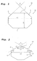
- Figure 1 is a schematic explanatory view of a transverse cross section of a tubular body having a transverse cross-sectional shape comprising a flat octagon.
- Figure 2 is a schematic explanatory view of a transverse cross section of a tubular body having a transverse cross-sectional shape comprising a flat octagon.
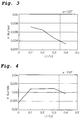
- Figure 3 is a graph showing the criticality of the ratio of
L 1 to L2 for the case in which the angle α is 135° . - Figure 4 is a graph showing the criticality of the ratio of L1 to L2 for the case in which the angle α is 150 ° .
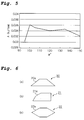
- Figure 5 is a graph showing the criticality of the angle α.
- Figures 6(a) - 6(c) are explanatory views showing examples of typical transverse cross-sectional shapes of a crash energy absorption member having a transverse cross-sectional shape which is a polygon other than an octagon.
- Figure 7 is a schematic explanatory view of the transverse cross-sectional shape of a crash energy absorption member in an example.
- Below, embodiments of the present invention along with their operation and effects will be described in detail.
- For an arbitrary flat cross-sectional shape actually applied to a crash energy absorption member, there exists a cross-sectional shape of a crash energy absorption member which can secure a level of shock absorption by stably buckling in the axial direction into the shape of a bellows without an increase in weight due to the addition of a partition or an increase in plate thickness.
- Namely, as a result of careful consideration making use of FEM numerical analysis, the present inventors made the findings set forth below as items (1) - (3).
- (1) Figure 1 is a schematic explanatory view showing a cross section of a crash
energy absorption member 10 formed from a tubular body having a transverse cross-sectional shape which is a polygon.
In Figure 1, if the length of aside 1 of aregular octagon 12 for which angle α is 90° is lengthened to form a flat shape, the greater is the flatness, the more unstable does buckling become. If angle α becomes smaller than 90°, buckling becomes still more unstable. Accordingly, angle α should be larger than 90°.
Here, "buckling is stable" means that collapse occurs by repeated buckling into the shape of a bellows. "Buckling becomes unstable" means that the occurrence of bending or the like in the course of collapse interferes with repeated buckling, and collapse does not take place in the shape of a bellows. - (2) Figure 2 is a schematic explanatory view showing a cross section similar to Figure 1. As shown in Figure 2, a
flat octagon 14 hasside 1 adjoined bysides sides side 1 approach each other such that the overall shape of an octagon is transformed to approach a lozenge shape, buckling becomes stable. - (3) If the lengths L1 and L3 of the
sides - Based on these fmdings (1) - (3), the present inventors performed diligent investigations of the relationship between angle α and lengths L1, L2 using as a reference an octagonal cross-sectional shape with a flatness of 2.0 formed by lengthening two opposing sides of a regular octagon measuring 35 mm on a side and having a sheet thickness of 1.6 mm to increase the length of the two sides to 119.5 mm. "Flatness" specifies the ratio of the lengths of a long side to short side of a rectangle which circumscribes the transverse cross section of a crash energy absorption member. For example, the flatness of the
octagon 12 shown in Figure 1 is calculated as (L2/L4). - Namely, in this investigation, the length of
side 1 of theoctagon 12 shown in Figure 1 was shortened, and the angle α betweensides side 1 shown in Figure 2 and the length ofside 1 were varied. - The distance L2 between the ends of
sides side 1 was fixed at 169 mm. In this example, the axial length of a crash energy absorption member was made 200 mm, and the energy absorbed at the time of collapse in the lengthwise direction of the crashenergy absorption member 14 when it was collapsed in the axial direction was compared. - The results are shown in the graphs of Figure 3 and Figure 4. The ordinate A in Figures 3 and 4 shows the energy absorbed during collapse (kJ/mm) per unit length of circumference when the amount of collapse in the axial direction was 130 mm.
- As can be seen from the graphs in Figures 3 and 4, when angle α is either 135° or 150°, by making the ratio of L1 to L2 (L1 /L2) so as to satisfy the following conditions, a sufficient amount of absorbed energy can be secured.
- In the graphs of Figures 3 and 4, the value on the abscissa (L1/L2) indicated by the dash and dot line is a value for which the
length L 1 ofside 1 becomes equal to the lengths ofsides side 1, an amount of absorbed energy can be secured. The reason for this is as explained below. - In general, when a crash energy absorption member having a polygonal transverse cross-sectional shape collapses in the lengthwise direction, the greater is the length of one side, the easier it is for bending to take place when this side buckles, and it displays unstable behavior.
- On the other hand, the larger are some of the internal angles formed by this polygon, the more unstable is buckling.
- If such unstable buckling occurs, the collapse load of the member markedly decreases compared to the case of stable buckling. As a result, the amount of absorbed energy up to a prescribed amount of collapse decreases.
- As shown in Figure 2, when the transverse cross-sectional shape of a crash energy absorption member is a flat polygon, internal angle θ1 formed by
side 1 andside 2 is large compared to internal angle 62 formed byside 2 andside 5 and internal angle θ3 formed byside 3 andside 4. - Accordingly,
side 2 andside 3 are more stable with respect to buckling than isside 1. In other words, in order to secure buckling stability of the crash energy absorption member as a whole by increasing the buckling stability ofside 1 to the same level as the buckling stability ofsides side 1 to be smaller than the lengths ofsides - Using L1 and L2 and angle α, this relationship is expressed by 0 < L1/L2 < 1/{2 x sin(α/2) + 1}.
- The flatness of crash energy absorption members which are actually used varies with the component. In order to elucidate a suitable lower limit for angle α, the influence of angle α on the stability of buckling of a crash energy absorption member having a relatively low flatness of 1.3 was investigated by varying angle α in a range of 95 ° and above. In this study, L2 was made 169 mm and L1 was made 50.7 mm, which satisfied the relationship prescribed by the above-described equation for any value of angle α. At this time, the value of (L1/L2) was 0.3.
- The results are shown in the graph of Figure 5. In the same manner as for the ordinate A in Figures 3 and 4, the ordinate A in Figure 5 shows the energy absorbed in collapse (kJ/mm) per unit length of circumference when the amount of collapse was 130 mm.
- As shown in the graph of Figure 5, If angle α is smaller than 100 °, the absorbed energy rapidly begins to decrease, and particularly when it becomes less than 97° as shown by a dash and dot line, the absorbed energy becomes extremely low, and there is no longer any practicality. This is because If angle α becomes smaller than 97°, the ridge lines at both ends of
side 1 in Figure 2 exhibit bending behavior, and buckling becomes unstable. - In this manner, by having angle α be in the range of at least 97° and at most 150°, a high level of absorbed energy is obtained. More preferably, angle α is at least 100° and at most 140° . As a result, a high level of absorbed energy can be stably secured.
- Even in cases in which angle α is in the range of at least 97° and at most 150°, when the ratio (L1/L2) is larger than the value satisfying the above-described range, the strength of
side 1 decreases, and large bending develops at the time of buckling. - The ratio (L1/L2) is preferably at least 20% of 1/{2 x sin(α/2) + 1}, and more preferably it is at least 50% of 1/{2 x sin(α/2) +1}.
- According to the present invention, the buckling of a crash energy absorption member having a transverse cross-sectional shape with an even larger flatness can be stabilized. Namely, the relationship [0 < L1/L2 < 1/{2 x sin(α/2) + 1}] between the angle α between
sides side 1 and lengths L1 and L2 which was described above while referring to Figures 1 - 5 is not applicable only to a crash energy absorption member having an octagonal transverse cross-sectional shape as shown in Figures 1-5. It is also applicable to a crash energy absorption member having a transverse cross-sectional shape which is a polygon other than an octagon and which has an arbitrary flatness. - Figure 6(a), Figure 6(b), and Figure 6(c) are explanatory views showing examples of typical transverse cross-sectional shapes of crash energy absorption members 20 - 22 having a transverse cross-sectional shape which is a polygon other than an octagon.
- Figure 6(a) shows the case of a
quadrangle 20a, Figure 6(b) shows the case of apentagon 21a, and Figure 6(c) shows the case of ahexagon 22a. - When a crash energy absorption member is installed as a component of a vehicle body, due to restrictions on installation space such as the installation space for the engine compartment, there are cases in which the transverse cross-sectional shape of a crash energy absorption member must be a non-symmetric shape such as that shown in Figure 6(b). The effects of the present invention are particularly prominent in such a case.
- The relationship between the angle α formed between
sides side 1 and the ratio (L1/L2) is not limited to the long side of a flat cross section, and if this relationship is satisfied by a portion of a polygon, the effects of the present invention are obtained. - A crash energy absorption member is usually installed in two locations which are symmetrical with respect to the widthwise direction of a vehicle body. Therefore, the transverse cross-sectional shapes of these two crash energy absorption members are preferably the same. However, in the case of an offset impact, the magnitudes of the impact forces acting on each of the two crash energy absorption members greatly differ, so taking into consideration the mode of impact, it is possible for the transverse cross-sectional shapes of these two crash energy absorption members to be different shapes.
- Thus, with a crash energy absorption member having a transverse cross-sectional shape comprising a polygon with a flatness of 2.0, for example, when the length L1 of
side 1 in Figure 2 is made 0, buckling becomes unstable during collapse, so impact energy cannot be sufficiently absorbed at the time of impact. - In contrast, according to the present invention, by the presence of
side 1 in Figure 2, buckling becomes stable, and it is easy to secure the absorption of energy. However, if the ratio (L1/L2) is set too high, it is easy for large bending deformation to occur at the time of buckling. Accordingly, by setting the ratio (L1/L2) to be in a prescribed range, stable buckling can be realized. By setting angle α to be within the above-described range, buckling is further stabilized. - A crash energy absorption member according to the present invention preferably does not have a flange which projects outwards from the outline of its transverse cross section. If a flange is provided, during collapse in the axial direction, the flange provides resistance against axial collapse deformation and functions as a sort of strut, and there are cases in which it causes bending of the crash energy absorption member in the lengthwise direction during collapse. Therefore, if a crash energy absorption member has a flange, the amount of absorbed energy at the time of impact greatly decreases compared to the case in which it does not have a flange.
- A crash energy absorption member according to the present invention may be manufactured by any method, and there are no particular restrictions on the manufacturing method. For example, it may be manufactured by extrusion, or a steel sheet having a prescribed thickness may be used as a blank, and it may be formed into a member for forming a tubular body having a polygonal transverse cross-sectional shape by press working, and the opposing ends of this member may be joined to each other by a suitable means such as welding.
- The crash energy absorption member according to the present invention is formed from a tubular body having a closed cross section.
- As described above, according to the present invention, a crash energy absorption member can be provided which can secure a prescribed amount of shock absorption by stably buckling in the axial direction into the shape of a bellows when an impact load is applied thereto without an increase in weight due to the addition of a partition or an increase in plate thickness and without causing bending in the axial direction.
- The present invention will be explained in detail while referring to
- The below-described impact test was carried out in order to verify the effects of the present invention.
- A high tensile strength steel sheet with a strength on the order of 590 MPa and a sheet thickness of 1.6 mm was used as a material for forming a crash energy absorption member according to the present invention. This material was subjected to press forming and welding to prepare a crash energy absorption member having a tubular body with a hexagonal or octagonal transverse cross-sectional shape and a length of 200 mm.
- This crash energy absorption member was vertically disposed, and then a weight which weighed 200 kgf was dropped in free fall from a height of 11.9 m so that it impacted with the crash energy absorption member in the axial direction at a speed of 55 km/hr. The absorbed energy was compared when the amount of collapse in the axial direction was 130 mm. The test results are compiled in Table 1.
Table 1 Example No. Shape Flatness L1/L2 Angle α (°) 1/(2 x sin(α/2)+1) Energy absorbed in collapse to 130 mm per unit length of circumference (kJ) State of collapse 1 octagon 2.0 0.30 135.0 0.35 0.0345 stable buckling 2 hexagon 2.0 0.00 147.5 0.34 0.0234 large bending 3 octagon 2.0 0.40 150.0 0.34 0.0265 large bending 4 hexagon 2.0 0.35 104.9 0.39 0.0359 stable buckling 5 octagon 1.3 0.35 120.0 0.37 0.0335 stable buckling 6 octagon 1.3 0.35 95.0 0.40 0.0297 bending 7 octagon 2.0 0.71 90.0 0.41 0.0288 large bending - In Examples Nos. 1 - 4 of Table 1, the flatness was 2.0, and L2 shown in Figure 2 was made 169 mm.
- In particular, in Example No. 1, the ratio (L1/L2) was made 0.3 and angle α was made 135°.
- In Example No. 2, the ratio (L1/L2) was made 0 to form a hexagonal transverse cross section, and angle α was made 147.5°.
- In Example No. 3, angle α was made 150° and the ratio (L1/L2) was made 0.4, which was larger than 1/[2 x sin(150°/2) + 1].
- In Example No. 4, the hexagonal transverse cross-sectional shape shown in Figure 7 was used, the ratio (L1/L2) was made 0.35, and angle α was made 104.9°.
- In Example No. 5 and Example No. 6, the flatness was made 1.3, and L2 was made 169 mm.
- In Example No. 5, the ratio (L1/L2) was made 0.35, and angle α was made 120°.
- In Example No. 6, the ratio (L1/L2) was made 0.35 as in Example No. 5, and angle α was made 95 ° .
- In Example No. 7, starting with a regular octagon having a side length of 35 mm, the lengths of two opposing
sides - As shown in Table 1, by employing a suitable range for the relationship between the ratio (L1/L2) and angle α, it is possible to stably secure a high level of absorbed energy with a crash energy absorption member having a flat polygonal cross-sectional shape.
- According to the present invention, a crash energy absorption member can be provided which can secure a prescribed amount of shock absorption by stably buckling in the axial direction into the shape of a bellows when an impact load is applied without an increase in weight due to the addition of a partition or an increase in plate thickness and without leading to bending in the axial direction.
- As a result, even in the case in which the crash energy absorption member has a high flatness, buckling is stable at the time of crash energy absorbing and a sufficient amount of shock absorption can be fully secured.
Claims (4)
- A crash energy absorption member having a tubular body which absorbs impact energy by buckling when an impact load is applied in the axial direction from one end in the axial direction, characterized in that the transverse cross-sectional shape of at least a portion in the axial direction of the tubular body is a polygon, and for at least one side forming the polygon, when the angle formed by the two sides which adjoin the one side is α, the relationship between the length (L1) of the one side and the distance (L2) between the two ends of the two sides which do not intersect the one side satisfies the following equation:

- A crash energy absorption member as set forth in claim 1 wherein the angle α is at least 97° and at most 150°.
- The crash energy absorption member as set forth in claim 1 or claim 2 wherein the polygon is an octagon.
- A crash energy absorption member as set forth in any one of claims 1 - 3 wherein the transverse cross-sectional shape of the entirety of the tubular body in the axial direction is a polygon.
Applications Claiming Priority (2)
| Application Number | Priority Date | Filing Date | Title |
|---|---|---|---|
| JP2003280951 | 2003-07-28 | ||
| PCT/JP2004/011110 WO2005010396A1 (en) | 2003-07-28 | 2004-07-28 | Impact-absorbing member |
Publications (3)
| Publication Number | Publication Date |
|---|---|
| EP1650466A1 true EP1650466A1 (en) | 2006-04-26 |
| EP1650466A4 EP1650466A4 (en) | 2007-08-01 |
| EP1650466B1 EP1650466B1 (en) | 2010-05-05 |
Family
ID=34100910
Family Applications (1)
| Application Number | Title | Priority Date | Filing Date |
|---|---|---|---|
| EP04771162A Expired - Lifetime EP1650466B1 (en) | 2003-07-28 | 2004-07-28 | Impact-absorbing member |
Country Status (6)
| Country | Link |
|---|---|
| US (1) | US7665586B2 (en) |
| EP (1) | EP1650466B1 (en) |
| JP (1) | JP4386036B2 (en) |
| CN (1) | CN100406768C (en) |
| DE (1) | DE602004027049D1 (en) |
| WO (1) | WO2005010396A1 (en) |
Cited By (2)
| Publication number | Priority date | Publication date | Assignee | Title |
|---|---|---|---|---|
| EP1640224A3 (en) * | 2004-09-28 | 2006-12-27 | Aisin Seiki Kabushiki Kaisha | Shock absorbing device for vehicle and shock absorbing structure for vehicle |
| DE102015006264A1 (en) | 2015-05-15 | 2015-12-17 | Daimler Ag | Energy absorption element for a vehicle, in particular a motor vehicle |
Families Citing this family (27)
| Publication number | Priority date | Publication date | Assignee | Title |
|---|---|---|---|---|
| JP5147003B2 (en) * | 2007-03-02 | 2013-02-20 | 新日鐵住金株式会社 | Side member |
| JP5126503B2 (en) * | 2008-02-04 | 2013-01-23 | 新日鐵住金株式会社 | Crash box and its mounting structure |
| US8641129B2 (en) * | 2008-09-19 | 2014-02-04 | Ford Global Technologies, Llc | Twelve-cornered strengthening member |
| US9187127B2 (en) | 2008-09-19 | 2015-11-17 | Ford Global Technologies, Llc | Twelve-cornered strengthening member, assemblies including a twelve-cornered strengthening member, and methods of manufacturing and joining the same |
| US9533710B2 (en) * | 2008-09-19 | 2017-01-03 | Ford Global Technologies, Llc | Twelve-cornered strengthening member |
| US8539737B2 (en) | 2008-09-19 | 2013-09-24 | Ford Global Technologies, Llc | Twelve-cornered strengthening member |
| JP5418724B2 (en) * | 2011-03-30 | 2014-02-19 | 新日鐵住金株式会社 | Metal hollow columnar member |
| US8459726B2 (en) | 2011-04-15 | 2013-06-11 | Ford Global Technologies, Llc. | Multi-cornered strengthening members |
| IN2014DN08618A (en) | 2012-04-10 | 2015-05-22 | Nippon Steel & Sumitomo Metal Corp | |
| CN104471094B (en) | 2012-07-20 | 2019-02-26 | 新日铁住金株式会社 | steel |
| EP2889395B1 (en) | 2012-08-21 | 2017-10-04 | Nippon Steel & Sumitomo Metal Corporation | Steel material |
| US9862428B2 (en) | 2012-12-06 | 2018-01-09 | Nippon Steel & Sumitomo Metal Corporation | Steel material and impact absorbing member |
| EP3056391B1 (en) * | 2013-10-09 | 2018-07-04 | Nippon Steel & Sumitomo Metal Corporation | Crush box and method for producing the same |
| US10315698B2 (en) | 2015-06-24 | 2019-06-11 | Ford Global Technologies, Llc | Sixteen-cornered strengthening member for vehicles |
| US9944323B2 (en) | 2015-10-27 | 2018-04-17 | Ford Global Technologies, Llc | Twenty-four-cornered strengthening member for vehicles |
| US9889887B2 (en) | 2016-01-20 | 2018-02-13 | Ford Global Technologies, Llc | Twelve-cornered strengthening member for a vehicle with straight and curved sides and an optimized straight side length to curved side radius ratio |
| US9789906B1 (en) | 2016-03-23 | 2017-10-17 | Ford Global Technologies, Llc | Twenty-eight-cornered strengthening member for vehicles |
| US10704638B2 (en) | 2016-04-26 | 2020-07-07 | Ford Global Technologies, Llc | Cellular structures with twelve-cornered cells |
| US10393315B2 (en) | 2016-04-26 | 2019-08-27 | Ford Global Technologies, Llc | Cellular structures with twelve-cornered cells |
| CN106043463B (en) * | 2016-08-18 | 2018-07-24 | 辽宁忠旺集团有限公司 | Large-scale car body aluminium alloy anticollision proximate matter and its production technology |
| US10473177B2 (en) | 2016-08-23 | 2019-11-12 | Ford Global Technologies, Llc | Cellular structures with sixteen-cornered cells |
| US10220881B2 (en) | 2016-08-26 | 2019-03-05 | Ford Global Technologies, Llc | Cellular structures with fourteen-cornered cells |
| US10279842B2 (en) | 2016-08-30 | 2019-05-07 | Ford Global Technologies, Llc | Twenty-eight-cornered strengthening member for vehicles |
| US10300947B2 (en) | 2016-08-30 | 2019-05-28 | Ford Global Technologies, Llc | Twenty-eight-cornered strengthening member for vehicles |
| US10429006B2 (en) | 2016-10-12 | 2019-10-01 | Ford Global Technologies, Llc | Cellular structures with twelve-cornered cells |
| US11292522B2 (en) | 2019-12-04 | 2022-04-05 | Ford Global Technologies, Llc | Splayed front horns for vehicle frames |
| USD1045716S1 (en) * | 2021-10-28 | 2024-10-08 | Soucy International Inc. | Tubular member for a vehicle accessory |
Family Cites Families (17)
| Publication number | Priority date | Publication date | Assignee | Title |
|---|---|---|---|---|
| US4272114A (en) * | 1976-12-22 | 1981-06-09 | Mitsubishi Jidosha Kogyo Kabushiki Kaisha | Impact absorbing device |
| US4190276A (en) * | 1976-12-22 | 1980-02-26 | Mitsubishi Jidosha Kogyo Kabushiki Kaisha | Deformable impact absorbing device for vehicles |
| JP3070399B2 (en) | 1994-07-19 | 2000-07-31 | 日産自動車株式会社 | Strength member structure of vehicle body |
| JPH08108863A (en) * | 1994-10-12 | 1996-04-30 | Honda Motor Co Ltd | Car front side frame structure |
| JPH08128487A (en) * | 1994-11-02 | 1996-05-21 | Nissan Motor Co Ltd | Energy absorbing material and manufacturing method thereof |
| US5913565A (en) * | 1995-09-22 | 1999-06-22 | Nissan Motor | Vehicle member |
| AU705222B2 (en) * | 1996-02-09 | 1999-05-20 | Toyota Jidosha Kabushiki Kaisha | Front structure of car body, and method of absorbing impact by means of the front structure |
| JP3676491B2 (en) * | 1996-04-12 | 2005-07-27 | 新日本製鐵株式会社 | Shock absorbing member |
| US6068330A (en) * | 1998-01-22 | 2000-05-30 | Honda Giken Kogyo Kabushiki Kaisha | Framework of an automobile body |
| JPH11208519A (en) | 1998-01-22 | 1999-08-03 | Honda Motor Co Ltd | Car body frame structure |
| JP2002104107A (en) * | 2000-09-28 | 2002-04-10 | Aisin Takaoka Ltd | Shock absorbing body for vehicle |
| JP3820867B2 (en) * | 2000-10-17 | 2006-09-13 | 三菱自動車工業株式会社 | Body structure |
| JP3854812B2 (en) * | 2001-03-27 | 2006-12-06 | 新日本製鐵株式会社 | Strength members for automobiles |
| JP4759871B2 (en) * | 2001-08-02 | 2011-08-31 | Jfeスチール株式会社 | Impact energy absorbing member |
| JP2004042883A (en) * | 2002-05-14 | 2004-02-12 | Aisin Seiki Co Ltd | Bumper device |
| US6588830B1 (en) * | 2002-07-01 | 2003-07-08 | Daimlerchrysler Corporation | Energy absorbing frame rail tip |
| JP2004106612A (en) * | 2002-09-17 | 2004-04-08 | Kobe Steel Ltd | Energy absorbing member for absorbing impact in axial direction |
-
2004
- 2004-07-28 DE DE602004027049T patent/DE602004027049D1/en not_active Expired - Lifetime
- 2004-07-28 JP JP2005512117A patent/JP4386036B2/en not_active Expired - Lifetime
- 2004-07-28 CN CN200480027876XA patent/CN100406768C/en not_active Expired - Lifetime
- 2004-07-28 EP EP04771162A patent/EP1650466B1/en not_active Expired - Lifetime
- 2004-07-28 WO PCT/JP2004/011110 patent/WO2005010396A1/en not_active Ceased
-
2006
- 2006-01-27 US US11/340,664 patent/US7665586B2/en not_active Expired - Lifetime
Non-Patent Citations (2)
| Title |
|---|
| No further relevant documents disclosed * |
| See also references of WO2005010396A1 * |
Cited By (3)
| Publication number | Priority date | Publication date | Assignee | Title |
|---|---|---|---|---|
| EP1640224A3 (en) * | 2004-09-28 | 2006-12-27 | Aisin Seiki Kabushiki Kaisha | Shock absorbing device for vehicle and shock absorbing structure for vehicle |
| US7213867B2 (en) | 2004-09-28 | 2007-05-08 | Aisin Seiki Kabushiki Kaisha | Shock absorbing device for vehicle and shock absorbing structure for vehicle |
| DE102015006264A1 (en) | 2015-05-15 | 2015-12-17 | Daimler Ag | Energy absorption element for a vehicle, in particular a motor vehicle |
Also Published As
| Publication number | Publication date |
|---|---|
| JP4386036B2 (en) | 2009-12-16 |
| EP1650466A4 (en) | 2007-08-01 |
| JPWO2005010396A1 (en) | 2006-10-05 |
| EP1650466B1 (en) | 2010-05-05 |
| DE602004027049D1 (en) | 2010-06-17 |
| CN1856671A (en) | 2006-11-01 |
| US7665586B2 (en) | 2010-02-23 |
| CN100406768C (en) | 2008-07-30 |
| US20060202511A1 (en) | 2006-09-14 |
| WO2005010396A1 (en) | 2005-02-03 |
Similar Documents
| Publication | Publication Date | Title |
|---|---|---|
| EP1650466B1 (en) | Impact-absorbing member | |
| EP1653114B1 (en) | Impact-absorbing member | |
| EP1653113B1 (en) | Impact-absorbing member | |
| EP1415865B1 (en) | Bumper beam for automobiles | |
| US20060249342A1 (en) | Vehicle structural element serving to absorb certain shocks by plastic deformation | |
| EP2541093B1 (en) | Impact absorbing member | |
| EP2889188A1 (en) | Crash box and automobile body | |
| JP2000062551A (en) | Bumper structure | |
| CN103717938A (en) | impact absorbing member | |
| JPH09277953A (en) | Shock absorbing member | |
| EP1468889B1 (en) | Coupler for a railway vehicle, with a rubber damper and energy absorbing members | |
| EP3932750B1 (en) | Structural member for vehicle | |
| CN220842679U (en) | Subframe of a vehicle, body component of a vehicle, and vehicle | |
| JP3167212B2 (en) | Side member | |
| EP3849849B1 (en) | Energy absorbing device, motor vehicle body and method for manufacturing thereof | |
| JP2012030624A (en) | Automobile bumper | |
| JPH0858499A (en) | Bumper stay | |
| JP3385798B2 (en) | Automotive frame material and method of manufacturing the same | |
| EP4467397A1 (en) | Bumper reinforcement with open cross section | |
| WO2023057890A1 (en) | Side intrusion beam | |
| JP3714484B2 (en) | Bumper reinforcement | |
| JPH0967657A (en) | Production of buffer member for vehicle | |
| JP2026025848A (en) | Automotive collision energy absorption parts | |
| KR20070071377A (en) | Reinforced Impact Beam | |
| KR20240172782A (en) | Collision Energy Absorption Members for Railway Vehicles |
Legal Events
| Date | Code | Title | Description |
|---|---|---|---|
| PUAI | Public reference made under article 153(3) epc to a published international application that has entered the european phase |
Free format text: ORIGINAL CODE: 0009012 |
|
| 17P | Request for examination filed |
Effective date: 20060213 |
|
| AK | Designated contracting states |
Kind code of ref document: A1 Designated state(s): DE FR GB |
|
| DAX | Request for extension of the european patent (deleted) | ||
| RBV | Designated contracting states (corrected) |
Designated state(s): DE FR GB |
|
| A4 | Supplementary search report drawn up and despatched |
Effective date: 20070704 |
|
| 17Q | First examination report despatched |
Effective date: 20080717 |
|
| GRAP | Despatch of communication of intention to grant a patent |
Free format text: ORIGINAL CODE: EPIDOSNIGR1 |
|
| GRAS | Grant fee paid |
Free format text: ORIGINAL CODE: EPIDOSNIGR3 |
|
| GRAA | (expected) grant |
Free format text: ORIGINAL CODE: 0009210 |
|
| AK | Designated contracting states |
Kind code of ref document: B1 Designated state(s): DE FR GB |
|
| REG | Reference to a national code |
Ref country code: GB Ref legal event code: FG4D |
|
| REF | Corresponds to: |
Ref document number: 602004027049 Country of ref document: DE Date of ref document: 20100617 Kind code of ref document: P |
|
| PLBE | No opposition filed within time limit |
Free format text: ORIGINAL CODE: 0009261 |
|
| STAA | Information on the status of an ep patent application or granted ep patent |
Free format text: STATUS: NO OPPOSITION FILED WITHIN TIME LIMIT |
|
| 26N | No opposition filed |
Effective date: 20110208 |
|
| REG | Reference to a national code |
Ref country code: DE Ref legal event code: R097 Ref document number: 602004027049 Country of ref document: DE Effective date: 20110207 |
|
| REG | Reference to a national code |
Ref country code: GB Ref legal event code: 732E Free format text: REGISTERED BETWEEN 20131010 AND 20131016 |
|
| REG | Reference to a national code |
Ref country code: FR Ref legal event code: TQ Owner name: TOYODA IRON WORKS CO., LTD., JP Effective date: 20131108 Ref country code: FR Ref legal event code: TQ Owner name: NIPPON STEEL & SUMITOMO METAL CORPORATION, JP Effective date: 20131108 |
|
| REG | Reference to a national code |
Ref country code: DE Ref legal event code: R081 Ref document number: 602004027049 Country of ref document: DE Owner name: TOYODA IRON WORKS CO., LTD., JP Free format text: FORMER OWNER: SUMITOMO METAL INDUSTRIES, LTD., TOYODA IRON WORKS CO., LTD., , JP Effective date: 20140403 Ref country code: DE Ref legal event code: R081 Ref document number: 602004027049 Country of ref document: DE Owner name: NIPPON STEEL & SUMITOMO METAL CORPORATION, JP Free format text: FORMER OWNER: SUMITOMO METAL INDUSTRIES, LTD., TOYODA IRON WORKS CO., LTD., , JP Effective date: 20140403 Ref country code: DE Ref legal event code: R082 Ref document number: 602004027049 Country of ref document: DE Representative=s name: LORENZ SEIDLER GOSSEL RECHTSANWAELTE PATENTANW, DE Effective date: 20140403 Ref country code: DE Ref legal event code: R081 Ref document number: 602004027049 Country of ref document: DE Owner name: TOYODA IRON WORKS CO., LTD., TOYOTA, JP Free format text: FORMER OWNER: SUMITOMO METAL INDUSTRIES, LTD., TOYODA IRON WORKS CO., LTD., , JP Effective date: 20140403 Ref country code: DE Ref legal event code: R081 Ref document number: 602004027049 Country of ref document: DE Owner name: NIPPON STEEL & SUMITOMO METAL CORPORATION, JP Free format text: FORMER OWNERS: SUMITOMO METAL INDUSTRIES, LTD., OSAKA, JP; TOYODA IRON WORKS CO., LTD., TOYOTA, AICHI, JP Effective date: 20140403 Ref country code: DE Ref legal event code: R081 Ref document number: 602004027049 Country of ref document: DE Owner name: TOYODA IRON WORKS CO., LTD., TOYOTA, JP Free format text: FORMER OWNERS: SUMITOMO METAL INDUSTRIES, LTD., OSAKA, JP; TOYODA IRON WORKS CO., LTD., TOYOTA, AICHI, JP Effective date: 20140403 |
|
| REG | Reference to a national code |
Ref country code: FR Ref legal event code: PLFP Year of fee payment: 13 |
|
| REG | Reference to a national code |
Ref country code: FR Ref legal event code: PLFP Year of fee payment: 14 |
|
| REG | Reference to a national code |
Ref country code: FR Ref legal event code: PLFP Year of fee payment: 15 |
|
| REG | Reference to a national code |
Ref country code: DE Ref legal event code: R082 Ref document number: 602004027049 Country of ref document: DE Representative=s name: LORENZ SEIDLER GOSSEL RECHTSANWAELTE PATENTANW, DE Ref country code: DE Ref legal event code: R081 Ref document number: 602004027049 Country of ref document: DE Owner name: NIPPON STEEL CORP., JP Free format text: FORMER OWNERS: NIPPON STEEL & SUMITOMO METAL CORPORATION, TOKYO, JP; TOYODA IRON WORKS CO., LTD., TOYOTA, AICHI, JP Ref country code: DE Ref legal event code: R081 Ref document number: 602004027049 Country of ref document: DE Owner name: TOYODA IRON WORKS CO., LTD., TOYOTA, JP Free format text: FORMER OWNERS: NIPPON STEEL & SUMITOMO METAL CORPORATION, TOKYO, JP; TOYODA IRON WORKS CO., LTD., TOYOTA, AICHI, JP |
|
| PGFP | Annual fee paid to national office [announced via postgrant information from national office to epo] |
Ref country code: FR Payment date: 20230620 Year of fee payment: 20 |
|
| PGFP | Annual fee paid to national office [announced via postgrant information from national office to epo] |
Ref country code: GB Payment date: 20230608 Year of fee payment: 20 |
|
| PGFP | Annual fee paid to national office [announced via postgrant information from national office to epo] |
Ref country code: DE Payment date: 20230531 Year of fee payment: 20 |
|
| REG | Reference to a national code |
Ref country code: DE Ref legal event code: R071 Ref document number: 602004027049 Country of ref document: DE |
|
| REG | Reference to a national code |
Ref country code: GB Ref legal event code: PE20 Expiry date: 20240727 |
|
| PG25 | Lapsed in a contracting state [announced via postgrant information from national office to epo] |
Ref country code: GB Free format text: LAPSE BECAUSE OF EXPIRATION OF PROTECTION Effective date: 20240727 |
|
| PG25 | Lapsed in a contracting state [announced via postgrant information from national office to epo] |
Ref country code: GB Free format text: LAPSE BECAUSE OF EXPIRATION OF PROTECTION Effective date: 20240727 |