EP1650425B1 - Liquid trap volume compensator - Google Patents
Liquid trap volume compensator Download PDFInfo
- Publication number
- EP1650425B1 EP1650425B1 EP04256440A EP04256440A EP1650425B1 EP 1650425 B1 EP1650425 B1 EP 1650425B1 EP 04256440 A EP04256440 A EP 04256440A EP 04256440 A EP04256440 A EP 04256440A EP 1650425 B1 EP1650425 B1 EP 1650425B1
- Authority
- EP
- European Patent Office
- Prior art keywords
- canister
- fuel
- trap
- liquid
- plate
- Prior art date
- Legal status (The legal status is an assumption and is not a legal conclusion. Google has not performed a legal analysis and makes no representation as to the accuracy of the status listed.)
- Expired - Lifetime
Links
- 239000007788 liquid Substances 0.000 title claims abstract description 74
- 239000000446 fuel Substances 0.000 claims abstract description 61
- 239000000463 material Substances 0.000 claims abstract description 49
- OKTJSMMVPCPJKN-UHFFFAOYSA-N Carbon Chemical compound [C] OKTJSMMVPCPJKN-UHFFFAOYSA-N 0.000 claims abstract description 33
- 238000013022 venting Methods 0.000 claims abstract description 4
- 238000001914 filtration Methods 0.000 claims abstract description 3
- 239000006260 foam Substances 0.000 claims description 10
- 238000012856 packing Methods 0.000 claims description 7
- 239000002250 absorbent Substances 0.000 claims 3
- 230000002745 absorbent Effects 0.000 claims 3
- 239000003463 adsorbent Substances 0.000 description 15
- OKTJSMMVPCPJKN-OUBTZVSYSA-N Carbon-13 Chemical compound [13C] OKTJSMMVPCPJKN-OUBTZVSYSA-N 0.000 description 9
- 238000010926 purge Methods 0.000 description 9
- 238000003466 welding Methods 0.000 description 4
- 229910052799 carbon Inorganic materials 0.000 description 3
- 108010063955 thrombin receptor peptide (42-47) Proteins 0.000 description 3
- 229910000831 Steel Inorganic materials 0.000 description 2
- 239000011521 glass Substances 0.000 description 2
- 239000004033 plastic Substances 0.000 description 2
- 229920003023 plastic Polymers 0.000 description 2
- 125000006850 spacer group Chemical group 0.000 description 2
- 239000010959 steel Substances 0.000 description 2
- 238000010521 absorption reaction Methods 0.000 description 1
- 238000000071 blow moulding Methods 0.000 description 1
- 230000000694 effects Effects 0.000 description 1
- 229920001903 high density polyethylene Polymers 0.000 description 1
- 239000004700 high-density polyethylene Substances 0.000 description 1
- 238000001746 injection moulding Methods 0.000 description 1
- 238000007789 sealing Methods 0.000 description 1
- 230000035939 shock Effects 0.000 description 1
- 239000000126 substance Substances 0.000 description 1
- 238000003856 thermoforming Methods 0.000 description 1
Images



Classifications
-
- F—MECHANICAL ENGINEERING; LIGHTING; HEATING; WEAPONS; BLASTING
- F02—COMBUSTION ENGINES; HOT-GAS OR COMBUSTION-PRODUCT ENGINE PLANTS
- F02M—SUPPLYING COMBUSTION ENGINES IN GENERAL WITH COMBUSTIBLE MIXTURES OR CONSTITUENTS THEREOF
- F02M25/00—Engine-pertinent apparatus for adding non-fuel substances or small quantities of secondary fuel to combustion-air, main fuel or fuel-air mixture
- F02M25/08—Engine-pertinent apparatus for adding non-fuel substances or small quantities of secondary fuel to combustion-air, main fuel or fuel-air mixture adding fuel vapours drawn from engine fuel reservoir
- F02M25/0854—Details of the absorption canister
-
- B—PERFORMING OPERATIONS; TRANSPORTING
- B01—PHYSICAL OR CHEMICAL PROCESSES OR APPARATUS IN GENERAL
- B01D—SEPARATION
- B01D2253/00—Adsorbents used in seperation treatment of gases and vapours
- B01D2253/10—Inorganic adsorbents
- B01D2253/102—Carbon
-
- B—PERFORMING OPERATIONS; TRANSPORTING
- B01—PHYSICAL OR CHEMICAL PROCESSES OR APPARATUS IN GENERAL
- B01D—SEPARATION
- B01D2257/00—Components to be removed
- B01D2257/70—Organic compounds not provided for in groups B01D2257/00 - B01D2257/602
- B01D2257/702—Hydrocarbons
- B01D2257/7022—Aliphatic hydrocarbons
-
- F—MECHANICAL ENGINEERING; LIGHTING; HEATING; WEAPONS; BLASTING
- F02—COMBUSTION ENGINES; HOT-GAS OR COMBUSTION-PRODUCT ENGINE PLANTS
- F02M—SUPPLYING COMBUSTION ENGINES IN GENERAL WITH COMBUSTIBLE MIXTURES OR CONSTITUENTS THEREOF
- F02M25/00—Engine-pertinent apparatus for adding non-fuel substances or small quantities of secondary fuel to combustion-air, main fuel or fuel-air mixture
- F02M25/08—Engine-pertinent apparatus for adding non-fuel substances or small quantities of secondary fuel to combustion-air, main fuel or fuel-air mixture adding fuel vapours drawn from engine fuel reservoir
- F02M2025/0863—Engine-pertinent apparatus for adding non-fuel substances or small quantities of secondary fuel to combustion-air, main fuel or fuel-air mixture adding fuel vapours drawn from engine fuel reservoir with means dealing with condensed fuel or water, e.g. having a liquid trap
Definitions
- the present invention relates to a canister for filtering fuel vapour in the venting loop of a fuel system, provided with a container for a filter material, such as activated carbon, the canister comprising a connection for an inlet line for guiding fuel vapour towards the canister, and a connection for an outlet line for purging fuel vapour from the canister, and a liquid trap for collecting liquid transported towards the canister via the inlet line.
- a filter material such as activated carbon
- the main function of evaporative canisters, as part of a fuel system, is to avoid vapour to escape by adsorbing HC coming from the tank.
- the canister forms part of the venting loop of a fuel system and prevents HC to be vented into the atmosphere.
- the canister is provided with an active component, such as activated carbon. This activated carbon catches HC which is present in the fuel vapour which is guided through the canister.
- a canister is typically provided with a liquid trap to collect liquid fuel which is guided towards the canister via the inlet line.
- the canister 1 is also provided with a connection 9 for connecting a purge line for purging the activated carbon 3.
- the canister 1 is provided with a canister body 2.
- the canister body 2 forms a container for receiving activated carbon 3.
- the activated carbon 3 at the top end thereof is covered by means of a layer 4, which allows the passing of a fuel vapour.
- the routing of the fuel vapour towards the activated carbon is indicated by a dotted line 5.
- a liquid trap 6 is welded to the canister body 2.
- liquid fuel can be received in the liquid trap 6.
- the liquid trap volume can vary, according to the orientation.
- the fuel trap 6 is provided with a connection 8 for connecting an inlet line from the fuel system to the canister 1.
- a disadvantage of the canister according to the prior art is the fact that the liquid trap has to be welded to the canister body as an additional part.
- An object of the present invention is to provide a canister according to the introduction, provided with a fuel trap, without the need of a welding operation to provide the liquid trap to the canister.
- liquid trap is positioned inside the canister body.
- a further advantage of avoiding a welding operation is that potential leaks on the welding joint are eliminated. The fact that no potential leaks can be created since there is no longer a welded zone is extremely important for the functioning of the canister.
- the fuel trap essentially has the form of a box, the box having a first opening for connecting the inlet line to the fuel trap and a second opening for releasing the fuel vapour towards the filter material.
- the fuel trap according to the present invention could be provided by positioning a fuel trap in the form of a reservoir, for instance by press-fit, inside the canister body. Because of the position of the fuel trap inside the canister body an additional welding operation to provide the fuel trap to the canister can be avoided.
- the canister body is formed of a first material and the fuel trap is formed of a second material.
- the fact that the fuel trap no longer has to be welded to the canister body enables the design of a canister having a canister body formed of a first material which is suitable for avoiding permeation of fuel vapour.
- the fuel trap could be formed of a different material which is especially suitable for avoided permeation of liquid fuel.
- the liquid trap could be formed of a low-permeation material like POM or another suitable low-permeation material, such as a suitable plastic, steel or glass or other material capable of retaining fuel. This enables to reduce the overall canister emission without requesting the change of the material of the canister body itself.
- a canister is provided with pressure means for exerting pressure on the filter material in order to improve the packing thereof, the pressure means comprising tension means, such as a spring, and a plate to apply a pressure to the filter material, wherein the fuel trap is integral with the plate, in that the plate is adapted to receive liquid.
- tension means such as a spring
- the plate is formed as a cup or tank.
- the pressure means provides volume compensation means in order to assure a reasonable packing of the filter material in case of canister body volume variations. These volume variations are due to thermal and chemical expansion of the canister parts or are due to mechanical effects, such as vibration and shocks exerted on the canister.
- the volume compensation means comprise a plate for transferring the pressure to the filter material, in order to thereby ensure a reasonable packing of the filter material.
- the plate in the form of a cup or tank, the plate is capable of receiving liquid fuel and therefore provides the liquid trap.
- the canister comprises a foam layer, wherein the foam layer with one side thereof adjoins the plate and with the opposite side thereof adjoins the filter materials.
- the plate is provided with distant means in order to create an open space between the foam layer and the surface of the plate adjoining the foam layer.
- the liquid trap has the form of an adsorbent material adapted to allow the fuel vapour to pass through the adsorbent material and to allow the liquid to be captured in the adsorbent material.
- FIG. 2 shows a canister 10 provided with a canister body 12 which forms a container for an active carbon 13.
- the active carbon at the top end thereof is covered with a layer 14, which layer allows the passage of a fuel vapour 15.
- the fuel vapour 15 is guided towards the canister via a connection 18 for connecting an inlet line.
- the canister body 12 is provided with an internal liquid trap 16.
- the liquid trap 16 has the form of a reservoir which is for instance by press-fitting, provided inside the canister body 12.
- the liquid trap 16 is leak-tight connected to the end part of the connection 18.
- the liquid trap 16 is provided with an opening 20 for allowing the passage of the fuel vapour from the liquid trap 16 towards the activated carbon 13.
- the liquid trap 16 could be formed by any appropriate means such as injection moulding, blow moulding of thermoforming.
- the liquid trap 16 could be formed from HDPE.
- the liquid trap 16 could be formed from a low permeation material like POM or an appropriate plastic, steel or glass. Since the canister body 12 is only subject to permeation of fuel vapour, the canister body itself could be formed from PP or PA.
- the canister 10 is also provided with a connection 19 for connecting a purge line to the canister.
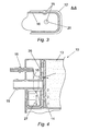
- Figure 3 shows in cross-section part of the liquid trap 16 and the canister body 12 according to line A-A as shown in Figure 2 .
- the opening 20 allows the passage of the fuel vapour 15.
- Figure 4 shows an alternative example of a canister.
- the canister 10 is adapted to be used in a position wherein the connections 18 and 19 in respect of inlet net line and the purge line are essentially in a horizontal position.
- the internal liquid trap 26 is adapted to receive liquid fuel in the bottom part thereof. With reference number 27, the maximum height of the liquid level inside the liquid trap 26 is indicated.
- FIG. 5 a further alternative example is shown of the canister 10.
- the canister body 12 is provided with activated carbon 13 at the top end thereof covered with a layer 14.
- an internal liquid trap 36 is positioned inside the canister body 12 inside the canister body 12.
- the internal liquid trap 36 is formed integral with the connection 38 occurring in that line and connection 39 for a first purge line.
- a sealing O-ring 40 and a latch 41 are provided.
- FIG. 6 a further example of the canister 10 is shown.
- the canister body 12 is provided with activated carbon 13 at the top end thereof covered with a layer 14.
- an internal liquid trap 46 is provided with a line 47 schematically the level of the liquid collected inside the liquid trap 46 as indicated.
- spring means in the form of a spring 48 are present.
- a pressure can be exerted on the activated carbon 13 in order to improve the packing thereof.
- the combination of an internal liquid trap 46 and a spring 48 provides both the liquid trap for the canister and the volume compensation means for the canister.
- the canister 10 comprises a canister body 12 having one connection 50 for an inlet net line and/or a purge line.
- the canister body 10 is provided with activated carbon 13 at a top end thereof covered with a layer 14.
- an internal liquid trap 56 is provided on top of the layer 14 .
- the internal liquid trap 56 comprises a plate-like element 57 and a container-like element 58.
- the plate-like element 57 is provided with openings 59 in order to allow the passage of a fuel vapour 15.
- the internal liquid trap 56 operates in co-operation with a spring 60 in order to exert a pressure on the activated carbon 13 inside the canister body 12. By exerting the pressure the packing of the activated carbon can be improved.
- the container-like element 58 of the internal liquid trap 56 is provided to collect liquid. By means of the line 61 schematically the level of liquid collected inside the internal liquid trap 56 is indicated.
- FIG 8 shows a further alternative embodiment of the canister 10 according to the present invention.
- the canister 10 comprises a canister body 12 forming a container for a filter material 13 such as activated carbon. At the top end thereof the carbon is covered by means of a foam layer 14. At the foam layer a spacer 75 is positioned. Between the wall of the canister body 12 and the spacer 75 a liquid trap 76 is present in the form of an adsorbent material.
- This adsorbent material could comprise any suitable material which is able to allow the fuel vapour guided towards the canister 10 via the connection 18 to pass through the liquid trap 76 towards the activated carbon 13.
- the adsorbent material 76 should be capable of capturing the liquid fuel which is transported towards the canister 10 via the inlet line.
- adsorbent material 76 Because of this embodiment, all liquid in the flow directed towards the canister 10 is captured in the adsorbent material 76 at the moment of inlet in the canister 10. Any liquid captured in the adsorbent material will migrate inside the material to a drier area.
- the adsorbent material 76 can be cleaned during purging, using a purging line which is to be connected to the connection 19 as shown in Figure 8 .
- the liquid trap volume can be reduced. There is a limited liquid action at the lower part of the adsorbent material 76. Contrary to existing canisters it is not necessary to have a separating wall surrounding the liquid trap, in order to reduce the risk of splashing of liquid fuel onto the activated carbon 13.
Landscapes
- Engineering & Computer Science (AREA)
- Chemical & Material Sciences (AREA)
- Combustion & Propulsion (AREA)
- Mechanical Engineering (AREA)
- General Engineering & Computer Science (AREA)
- Supplying Secondary Fuel Or The Like To Fuel, Air Or Fuel-Air Mixtures (AREA)
- Fluid-Pressure Circuits (AREA)
- Centrifugal Separators (AREA)
- Cooling, Air Intake And Gas Exhaust, And Fuel Tank Arrangements In Propulsion Units (AREA)
Abstract
Description
- The present invention relates to a canister for filtering fuel vapour in the venting loop of a fuel system, provided with a container for a filter material, such as activated carbon, the canister comprising a connection for an inlet line for guiding fuel vapour towards the canister, and a connection for an outlet line for purging fuel vapour from the canister, and a liquid trap for collecting liquid transported towards the canister via the inlet line.
- The main function of evaporative canisters, as part of a fuel system, is to avoid vapour to escape by adsorbing HC coming from the tank. The canister forms part of the venting loop of a fuel system and prevents HC to be vented into the atmosphere. In order to perform this function the canister is provided with an active component, such as activated carbon. This activated carbon catches HC which is present in the fuel vapour which is guided through the canister.
- The capability of absorption of HC by the activated carbon is degraded in case the carbon comes into contact with liquid fuel. Therefore a canister is typically provided with a liquid trap to collect liquid fuel which is guided towards the canister via the inlet line.
- A canister according the prior art, being similar to those disclosed in
WO 95/08059 US 5 641 344 , is shown inFigure 1 . Thecanister 1 is also provided with aconnection 9 for connecting a purge line for purging the activatedcarbon 3. - The
canister 1 is provided with acanister body 2. Thecanister body 2 forms a container for receiving activatedcarbon 3. The activatedcarbon 3 at the top end thereof is covered by means of alayer 4, which allows the passing of a fuel vapour. The routing of the fuel vapour towards the activated carbon is indicated by a dotted line 5. In order to assure that only fuel vapour is guided towards the activatedcarbon 3, and liquid fuel is not guided towards the activatedcarbon 3, a liquid trap 6 is welded to thecanister body 2. As schematically indicated byline 7, liquid fuel can be received in the liquid trap 6. The liquid trap volume can vary, according to the orientation. In order to guide the fuel vapour 5 towards the activatedcarbon 3, the fuel trap 6 is provided with aconnection 8 for connecting an inlet line from the fuel system to thecanister 1. - A disadvantage of the canister according to the prior art is the fact that the liquid trap has to be welded to the canister body as an additional part. An object of the present invention is to provide a canister according to the introduction, provided with a fuel trap, without the need of a welding operation to provide the liquid trap to the canister.
- This object is achieved in that the liquid trap is positioned inside the canister body. A further advantage of avoiding a welding operation is that potential leaks on the welding joint are eliminated. The fact that no potential leaks can be created since there is no longer a welded zone is extremely important for the functioning of the canister.
- According to the present invention it is possible that the fuel trap essentially has the form of a box, the box having a first opening for connecting the inlet line to the fuel trap and a second opening for releasing the fuel vapour towards the filter material.
- The fuel trap according to the present invention could be provided by positioning a fuel trap in the form of a reservoir, for instance by press-fit, inside the canister body. Because of the position of the fuel trap inside the canister body an additional welding operation to provide the fuel trap to the canister can be avoided.
- According to the present invention it is possible that the canister body is formed of a first material and the fuel trap is formed of a second material.
- The fact that the fuel trap no longer has to be welded to the canister body enables the design of a canister having a canister body formed of a first material which is suitable for avoiding permeation of fuel vapour. The fuel trap could be formed of a different material which is especially suitable for avoided permeation of liquid fuel. The liquid trap could be formed of a low-permeation material like POM or another suitable low-permeation material, such as a suitable plastic, steel or glass or other material capable of retaining fuel. This enables to reduce the overall canister emission without requesting the change of the material of the canister body itself.
- According to the present invention a canister is provided with pressure means for exerting pressure on the filter material in order to improve the packing thereof, the pressure means comprising tension means, such as a spring, and a plate to apply a pressure to the filter material, wherein the fuel trap is integral with the plate, in that the plate is adapted to receive liquid.
- Moreover, it is possible that the plate is formed as a cup or tank.
- The pressure means provides volume compensation means in order to assure a reasonable packing of the filter material in case of canister body volume variations. These volume variations are due to thermal and chemical expansion of the canister parts or are due to mechanical effects, such as vibration and shocks exerted on the canister.
- According to the invention the volume compensation means comprise a plate for transferring the pressure to the filter material, in order to thereby ensure a reasonable packing of the filter material. By designing the plate in the form of a cup or tank, the plate is capable of receiving liquid fuel and therefore provides the liquid trap.
- According to the present invention is possible that the canister comprises a foam layer, wherein the foam layer with one side thereof adjoins the plate and with the opposite side thereof adjoins the filter materials.
- Moreover it is possible that the plate is provided with distant means in order to create an open space between the foam layer and the surface of the plate adjoining the foam layer.
- According to the present invention it is possible that the liquid trap has the form of an adsorbent material adapted to allow the fuel vapour to pass through the adsorbent material and to allow the liquid to be captured in the adsorbent material.
- The present invention will now be described, with reference to the accompanying drawings, in which:
-
Figure 1 shows a canister and a fuel trap according to the prior art. -
Figure 2 shows a first example of a canister with an internal fuel trap. -
Figure 3 shows a part of the canister according toFigure 2 in cross-section according to line A-A. -
Figure 4 shows a second example of a canister with an internal fuel trap -
Figure 5 shows a third example of a canister with an internal fuel trap. -
Figure 6 shows a canister provided with volume compensation means in order to improve the packing of the filter material. -
Figure 7 shows a canister according to the present invention -
Figure 8 shows a canister according to the present invention with a liquid trap in the form of an adsorbent material. -
Figure 2 shows acanister 10 provided with acanister body 12 which forms a container for anactive carbon 13. The active carbon at the top end thereof is covered with alayer 14, which layer allows the passage of afuel vapour 15. Thefuel vapour 15 is guided towards the canister via aconnection 18 for connecting an inlet line. As clearly shown inFigure 2 , thecanister body 12 is provided with aninternal liquid trap 16. Theliquid trap 16 has the form of a reservoir which is for instance by press-fitting, provided inside thecanister body 12. Theliquid trap 16 is leak-tight connected to the end part of theconnection 18. Theliquid trap 16 is provided with anopening 20 for allowing the passage of the fuel vapour from theliquid trap 16 towards the activatedcarbon 13. Theliquid trap 16 could be formed by any appropriate means such as injection moulding, blow moulding of thermoforming. Theliquid trap 16 could be formed from HDPE. Alternatively, theliquid trap 16 could be formed from a low permeation material like POM or an appropriate plastic, steel or glass. Since thecanister body 12 is only subject to permeation of fuel vapour, the canister body itself could be formed from PP or PA. - The
canister 10 is also provided with aconnection 19 for connecting a purge line to the canister. -
Figure 3 shows in cross-section part of theliquid trap 16 and thecanister body 12 according to line A-A as shown inFigure 2 . InFigure 3 it is shown that theopening 20 allows the passage of thefuel vapour 15. -
Figure 4 shows an alternative example of a canister. Thecanister 10 is adapted to be used in a position wherein theconnections internal liquid trap 26 is adapted to receive liquid fuel in the bottom part thereof. Withreference number 27, the maximum height of the liquid level inside theliquid trap 26 is indicated. - In
Figure 5 a further alternative example is shown of thecanister 10. Thecanister body 12 is provided with activatedcarbon 13 at the top end thereof covered with alayer 14. Inside thecanister body 12 an internalliquid trap 36 is positioned. The internalliquid trap 36 is formed integral with theconnection 38 occurring in that line andconnection 39 for a first purge line. - In order to improve the connection of the internal
liquid trap 36 inside thecanister body 12, a sealing O-ring 40 and alatch 41 are provided. - In
Figure 6 a further example of thecanister 10 is shown. Thecanister body 12 is provided with activatedcarbon 13 at the top end thereof covered with alayer 14. Inside thecanister body 12 an internalliquid trap 46 is provided with aline 47 schematically the level of the liquid collected inside theliquid trap 46 as indicated. - In the example or according to
Figure 6 spring means in the form of aspring 48 are present. By means of thespring 48 and the internal liquid trap 46 a pressure can be exerted on the activatedcarbon 13 in order to improve the packing thereof. It is known in the prior art to provide a plate and a spring in order to provide volume compensating means. The combination of an internalliquid trap 46 and aspring 48 provides both the liquid trap for the canister and the volume compensation means for the canister. - The combination of volume compensation means and an internal liquid trap according to the invention as in the appended claims is shown in
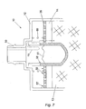
Figure 7 . Thecanister 10 according toFigure 7 comprises acanister body 12 having oneconnection 50 for an inlet net line and/or a purge line. Thecanister body 10 is provided with activatedcarbon 13 at a top end thereof covered with alayer 14. On top of thelayer 14 an internalliquid trap 56 is provided.
The internalliquid trap 56 comprises a plate-like element 57 and a container-like element 58. The plate-like element 57 is provided withopenings 59 in order to allow the passage of afuel vapour 15. The internalliquid trap 56 operates in co-operation with aspring 60 in order to exert a pressure on the activatedcarbon 13 inside thecanister body 12. By exerting the pressure the packing of the activated carbon can be improved. The container-like element 58 of the internalliquid trap 56 is provided to collect liquid. By means of theline 61 schematically the level of liquid collected inside the internalliquid trap 56 is indicated. -
Figure 8 shows a further alternative embodiment of thecanister 10 according to the present invention. Thecanister 10 comprises acanister body 12 forming a container for afilter material 13 such as activated carbon. At the top end thereof the carbon is covered by means of afoam layer 14. At the foam layer aspacer 75 is positioned. Between the wall of thecanister body 12 and the spacer 75 aliquid trap 76 is present in the form of an adsorbent material. This adsorbent material could comprise any suitable material which is able to allow the fuel vapour guided towards thecanister 10 via theconnection 18 to pass through theliquid trap 76 towards the activatedcarbon 13. At the same time theadsorbent material 76 should be capable of capturing the liquid fuel which is transported towards thecanister 10 via the inlet line. - Because of this embodiment, all liquid in the flow directed towards the
canister 10 is captured in theadsorbent material 76 at the moment of inlet in thecanister 10. Any liquid captured in the adsorbent material will migrate inside the material to a drier area. Theadsorbent material 76 can be cleaned during purging, using a purging line which is to be connected to theconnection 19 as shown inFigure 8 . - One of the advantages of having an adsorbent material as a liquid trap is the fact that the liquid captured inside the material will evaporate faster from the
adsorbent material 76 than it would evaporate from the surface of an amount of liquid present in a reservoir. The reason for this is the much bigger exchange area of the adsorbent material and the surrounding air. - Because of the adsorbent material the liquid trap volume can be reduced. There is a limited liquid action at the lower part of the
adsorbent material 76. Contrary to existing canisters it is not necessary to have a separating wall surrounding the liquid trap, in order to reduce the risk of splashing of liquid fuel onto the activatedcarbon 13.
Claims (9)
- Canister (10), for filtering fuel vapour in the venting loop of a fuel system, provided with a canister body (12) forming a container for filter material (13), such as activated carbon, the canister comprising a connection (18) for an inlet line for guiding fuel vapour towards the canister (10), and a liquid trap (16) for the collection of liquid transported towards the canister (10) via the inlet line the liquid trap being positioned inside the canister body (12) , wherein the canister (10) is provided with pressure means (48) for exerting pressure on the filter material (13) in order to improve the packing thereof, the pressure means (18) comprising tension means, such as a spring, and a plate (57) to transfer the pressure to the filter material (13) , characterised by the liquid trap (16) being integral with the plate (57) in that the plate (57) is provided with a container (58) for receiving liquid.
- Canister, according to claim 1, wherein the fuel trap (16) essentially has the form of a box, the box having a first opening for connecting the inlet line to the fuel trap and a second opening for releasing the fuel vapour towards the filter material(13).
- Canister according to claim 1 or 2, wherein the canister body (12) is formed of a first material and the fuel trap (16) is formed of a second material.
- Canister according to claim 3, wherein the fuel trap (16) is formed of a low permeation material.
- Canister according to any preceding claim, wherein the plate (57) is formed as a cup or tank.
- Canister according to any preceding claim, wherein the canister (10) comprises a foam layer (14), wherein the foam layer (14) with one side thereof adjoins the plate (57) and with the opposite side thereof adjoins the filter materials.
- Canister according to claim 6, wherein the plate (57) is provided with distant means in order to create an open space between the foam layer (14) and the surface of the plate (57) adjoining the foam layer (14).
- Canister according to any preceding claim, wherein the liquid trap (16) has the form of an absorbent material adapted to allow the fuel vapour to pass through the absorbent material and to allow the liquid to be captured in the absorbent material.
- Fuel system, comprising a canister according to any preceding claim.
Priority Applications (3)
| Application Number | Priority Date | Filing Date | Title |
|---|---|---|---|
| EP04256440A EP1650425B1 (en) | 2004-10-20 | 2004-10-20 | Liquid trap volume compensator |
| AT04256440T ATE398233T1 (en) | 2004-10-20 | 2004-10-20 | VOLUME COMPENSATOR WITH LIQUID TRAP |
| DE602004014382T DE602004014382D1 (en) | 2004-10-20 | 2004-10-20 | Volume compensator with liquid trap |
Applications Claiming Priority (1)
| Application Number | Priority Date | Filing Date | Title |
|---|---|---|---|
| EP04256440A EP1650425B1 (en) | 2004-10-20 | 2004-10-20 | Liquid trap volume compensator |
Publications (2)
| Publication Number | Publication Date |
|---|---|
| EP1650425A1 EP1650425A1 (en) | 2006-04-26 |
| EP1650425B1 true EP1650425B1 (en) | 2008-06-11 |
Family
ID=34930744
Family Applications (1)
| Application Number | Title | Priority Date | Filing Date |
|---|---|---|---|
| EP04256440A Expired - Lifetime EP1650425B1 (en) | 2004-10-20 | 2004-10-20 | Liquid trap volume compensator |
Country Status (3)
| Country | Link |
|---|---|
| EP (1) | EP1650425B1 (en) |
| AT (1) | ATE398233T1 (en) |
| DE (1) | DE602004014382D1 (en) |
Families Citing this family (3)
| Publication number | Priority date | Publication date | Assignee | Title |
|---|---|---|---|---|
| EP2738378B1 (en) * | 2012-11-29 | 2015-08-26 | Kautex Textron Gmbh&Co. Kg | Carbon canister including liquid separator |
| WO2014082899A1 (en) * | 2012-11-28 | 2014-06-05 | Kautex Textron Gmbh & Co. Kg | Carbon canister including liquid separator |
| JP2015124614A (en) * | 2013-12-25 | 2015-07-06 | 愛三工業株式会社 | Evaporated fuel treating device |
Family Cites Families (5)
| Publication number | Priority date | Publication date | Assignee | Title |
|---|---|---|---|---|
| JPS59165854A (en) * | 1983-03-09 | 1984-09-19 | Aisan Ind Co Ltd | Device for preventing fuel vaporization loss |
| US4655189A (en) * | 1984-03-31 | 1987-04-07 | Toyota Jidosha Kabushiki Kaisha | Device for processing fuel vapor |
| JPH04121450A (en) * | 1990-09-12 | 1992-04-22 | Toyota Motor Corp | Evaporated fuel treating equipment |
| DE9313840U1 (en) * | 1993-09-13 | 1993-12-02 | Expert Maschinenbau Gmbh, 64653 Lorsch | Activated carbon filter for motor vehicles |
| US5641344A (en) * | 1994-12-05 | 1997-06-24 | Tsuchiya Mfg., Co., Ltd. | Fuel vapor treatment device |
-
2004
- 2004-10-20 DE DE602004014382T patent/DE602004014382D1/en not_active Expired - Fee Related
- 2004-10-20 AT AT04256440T patent/ATE398233T1/en not_active IP Right Cessation
- 2004-10-20 EP EP04256440A patent/EP1650425B1/en not_active Expired - Lifetime
Also Published As
| Publication number | Publication date |
|---|---|
| EP1650425A1 (en) | 2006-04-26 |
| ATE398233T1 (en) | 2008-07-15 |
| DE602004014382D1 (en) | 2008-07-24 |
Similar Documents
| Publication | Publication Date | Title |
|---|---|---|
| US6578597B2 (en) | Fuel tank vent system with liquid fuel filter | |
| US6895943B1 (en) | Fuel vent assembly with floatless rollover protection | |
| US20110168715A1 (en) | Fuel cap with emissions protection | |
| US20080092857A1 (en) | Passive evaporative emission control module | |
| US4507132A (en) | Fuel evaporation preventing device | |
| US7909024B2 (en) | Hydrocarbon fuel vapour filter system | |
| US20090139495A1 (en) | Carbon canister with purge buffer system | |
| US20030145731A1 (en) | Storage apparatus | |
| US20210016219A1 (en) | Canister | |
| KR101413870B1 (en) | Double shut-off fuel supply valve | |
| EP1650425A1 (en) | Liquid trap volume compensator | |
| US10653994B2 (en) | Fuel vapor filter for a tank ventilating device of a motor vehicle with improved charging properties | |
| JP2002048015A (en) | Evaporating fuel processing canister | |
| JP6532573B2 (en) | Fuel steam processor | |
| US9243594B2 (en) | Hydrocarbon storage canister | |
| EP0556488B1 (en) | Fuel vapour storage canister | |
| WO2005023573A2 (en) | Evaporative emissions canister with incorporated liquid trap | |
| RU2194185C2 (en) | Adsorber of fuel evaporation control system | |
| CN101336341A (en) | Filtration device for use with a fuel vapor recovery system | |
| JP2010280317A (en) | Fuel tank and method of manufacturing the same | |
| RU2176745C2 (en) | Fuel fumes entrapping system adsorber | |
| JP2016176342A (en) | Canister | |
| US7350511B1 (en) | Fuel vapor control system | |
| RU2474722C1 (en) | Adsorber of fuel vapours recovery system | |
| US20050229787A1 (en) | Evaporative emissions canister partition |
Legal Events
| Date | Code | Title | Description |
|---|---|---|---|
| PUAI | Public reference made under article 153(3) epc to a published international application that has entered the european phase |
Free format text: ORIGINAL CODE: 0009012 |
|
| 17P | Request for examination filed |
Effective date: 20050824 |
|
| AK | Designated contracting states |
Kind code of ref document: A1 Designated state(s): AT BE BG CH CY CZ DE DK EE ES FI FR GB GR HU IE IT LI LU MC NL PL PT RO SE SI SK TR |
|
| AX | Request for extension of the european patent |
Extension state: AL HR LT LV MK |
|
| AKX | Designation fees paid |
Designated state(s): AT BE BG CH CY CZ DE DK EE ES FI FR GB GR HU IE IT LI LU MC NL PL PT RO SE SI SK TR |
|
| GRAP | Despatch of communication of intention to grant a patent |
Free format text: ORIGINAL CODE: EPIDOSNIGR1 |
|
| RIN1 | Information on inventor provided before grant (corrected) |
Inventor name: ZUCHARA, PAWEL Inventor name: ABIDI, MOSTAFA Inventor name: KRAWIEC, ZBIGNIEW Inventor name: NIEWIADOMSKI, MACIEJ Inventor name: LOEVENBRUCK, REMI |
|
| GRAS | Grant fee paid |
Free format text: ORIGINAL CODE: EPIDOSNIGR3 |
|
| GRAA | (expected) grant |
Free format text: ORIGINAL CODE: 0009210 |
|
| AK | Designated contracting states |
Kind code of ref document: B1 Designated state(s): AT BE BG CH CY CZ DE DK EE ES FI FR GB GR HU IE IT LI LU MC NL PL PT RO SE SI SK TR |
|
| REG | Reference to a national code |
Ref country code: GB Ref legal event code: FG4D |
|
| REG | Reference to a national code |
Ref country code: CH Ref legal event code: EP |
|
| REF | Corresponds to: |
Ref document number: 602004014382 Country of ref document: DE Date of ref document: 20080724 Kind code of ref document: P |
|
| REG | Reference to a national code |
Ref country code: IE Ref legal event code: FG4D |
|
| PG25 | Lapsed in a contracting state [announced via postgrant information from national office to epo] |
Ref country code: SI Free format text: LAPSE BECAUSE OF FAILURE TO SUBMIT A TRANSLATION OF THE DESCRIPTION OR TO PAY THE FEE WITHIN THE PRESCRIBED TIME-LIMIT Effective date: 20080611 Ref country code: FI Free format text: LAPSE BECAUSE OF FAILURE TO SUBMIT A TRANSLATION OF THE DESCRIPTION OR TO PAY THE FEE WITHIN THE PRESCRIBED TIME-LIMIT Effective date: 20080611 |
|
| PG25 | Lapsed in a contracting state [announced via postgrant information from national office to epo] |
Ref country code: AT Free format text: LAPSE BECAUSE OF FAILURE TO SUBMIT A TRANSLATION OF THE DESCRIPTION OR TO PAY THE FEE WITHIN THE PRESCRIBED TIME-LIMIT Effective date: 20080611 Ref country code: NL Free format text: LAPSE BECAUSE OF FAILURE TO SUBMIT A TRANSLATION OF THE DESCRIPTION OR TO PAY THE FEE WITHIN THE PRESCRIBED TIME-LIMIT Effective date: 20080611 Ref country code: PL Free format text: LAPSE BECAUSE OF FAILURE TO SUBMIT A TRANSLATION OF THE DESCRIPTION OR TO PAY THE FEE WITHIN THE PRESCRIBED TIME-LIMIT Effective date: 20080611 |
|
| NLV1 | Nl: lapsed or annulled due to failure to fulfill the requirements of art. 29p and 29m of the patents act | ||
| PG25 | Lapsed in a contracting state [announced via postgrant information from national office to epo] |
Ref country code: SE Free format text: LAPSE BECAUSE OF FAILURE TO SUBMIT A TRANSLATION OF THE DESCRIPTION OR TO PAY THE FEE WITHIN THE PRESCRIBED TIME-LIMIT Effective date: 20080911 Ref country code: PT Free format text: LAPSE BECAUSE OF FAILURE TO SUBMIT A TRANSLATION OF THE DESCRIPTION OR TO PAY THE FEE WITHIN THE PRESCRIBED TIME-LIMIT Effective date: 20081111 Ref country code: CZ Free format text: LAPSE BECAUSE OF FAILURE TO SUBMIT A TRANSLATION OF THE DESCRIPTION OR TO PAY THE FEE WITHIN THE PRESCRIBED TIME-LIMIT Effective date: 20080611 Ref country code: ES Free format text: LAPSE BECAUSE OF FAILURE TO SUBMIT A TRANSLATION OF THE DESCRIPTION OR TO PAY THE FEE WITHIN THE PRESCRIBED TIME-LIMIT Effective date: 20080922 |
|
| PG25 | Lapsed in a contracting state [announced via postgrant information from national office to epo] |
Ref country code: SK Free format text: LAPSE BECAUSE OF FAILURE TO SUBMIT A TRANSLATION OF THE DESCRIPTION OR TO PAY THE FEE WITHIN THE PRESCRIBED TIME-LIMIT Effective date: 20080611 Ref country code: RO Free format text: LAPSE BECAUSE OF FAILURE TO SUBMIT A TRANSLATION OF THE DESCRIPTION OR TO PAY THE FEE WITHIN THE PRESCRIBED TIME-LIMIT Effective date: 20080611 Ref country code: BE Free format text: LAPSE BECAUSE OF FAILURE TO SUBMIT A TRANSLATION OF THE DESCRIPTION OR TO PAY THE FEE WITHIN THE PRESCRIBED TIME-LIMIT Effective date: 20080611 |
|
| PLBE | No opposition filed within time limit |
Free format text: ORIGINAL CODE: 0009261 |
|
| STAA | Information on the status of an ep patent application or granted ep patent |
Free format text: STATUS: NO OPPOSITION FILED WITHIN TIME LIMIT |
|
| PG25 | Lapsed in a contracting state [announced via postgrant information from national office to epo] |
Ref country code: EE Free format text: LAPSE BECAUSE OF FAILURE TO SUBMIT A TRANSLATION OF THE DESCRIPTION OR TO PAY THE FEE WITHIN THE PRESCRIBED TIME-LIMIT Effective date: 20080611 Ref country code: DK Free format text: LAPSE BECAUSE OF FAILURE TO SUBMIT A TRANSLATION OF THE DESCRIPTION OR TO PAY THE FEE WITHIN THE PRESCRIBED TIME-LIMIT Effective date: 20080611 Ref country code: BG Free format text: LAPSE BECAUSE OF FAILURE TO SUBMIT A TRANSLATION OF THE DESCRIPTION OR TO PAY THE FEE WITHIN THE PRESCRIBED TIME-LIMIT Effective date: 20080911 |
|
| 26N | No opposition filed |
Effective date: 20090312 |
|
| PG25 | Lapsed in a contracting state [announced via postgrant information from national office to epo] |
Ref country code: MC Free format text: LAPSE BECAUSE OF NON-PAYMENT OF DUE FEES Effective date: 20081031 |
|
| REG | Reference to a national code |
Ref country code: CH Ref legal event code: PL |
|
| GBPC | Gb: european patent ceased through non-payment of renewal fee |
Effective date: 20081020 |
|
| REG | Reference to a national code |
Ref country code: FR Ref legal event code: ST Effective date: 20090630 |
|
| PG25 | Lapsed in a contracting state [announced via postgrant information from national office to epo] |
Ref country code: DE Free format text: LAPSE BECAUSE OF NON-PAYMENT OF DUE FEES Effective date: 20090501 Ref country code: IT Free format text: LAPSE BECAUSE OF NON-PAYMENT OF DUE FEES Effective date: 20081020 |
|
| PG25 | Lapsed in a contracting state [announced via postgrant information from national office to epo] |
Ref country code: IE Free format text: LAPSE BECAUSE OF NON-PAYMENT OF DUE FEES Effective date: 20081020 Ref country code: LI Free format text: LAPSE BECAUSE OF NON-PAYMENT OF DUE FEES Effective date: 20081031 Ref country code: FR Free format text: LAPSE BECAUSE OF NON-PAYMENT OF DUE FEES Effective date: 20081031 Ref country code: CH Free format text: LAPSE BECAUSE OF NON-PAYMENT OF DUE FEES Effective date: 20081031 |
|
| PG25 | Lapsed in a contracting state [announced via postgrant information from national office to epo] |
Ref country code: GB Free format text: LAPSE BECAUSE OF NON-PAYMENT OF DUE FEES Effective date: 20081020 |
|
| PG25 | Lapsed in a contracting state [announced via postgrant information from national office to epo] |
Ref country code: HU Free format text: LAPSE BECAUSE OF FAILURE TO SUBMIT A TRANSLATION OF THE DESCRIPTION OR TO PAY THE FEE WITHIN THE PRESCRIBED TIME-LIMIT Effective date: 20081212 Ref country code: LU Free format text: LAPSE BECAUSE OF NON-PAYMENT OF DUE FEES Effective date: 20081020 Ref country code: CY Free format text: LAPSE BECAUSE OF FAILURE TO SUBMIT A TRANSLATION OF THE DESCRIPTION OR TO PAY THE FEE WITHIN THE PRESCRIBED TIME-LIMIT Effective date: 20080611 |
|
| PG25 | Lapsed in a contracting state [announced via postgrant information from national office to epo] |
Ref country code: TR Free format text: LAPSE BECAUSE OF FAILURE TO SUBMIT A TRANSLATION OF THE DESCRIPTION OR TO PAY THE FEE WITHIN THE PRESCRIBED TIME-LIMIT Effective date: 20080611 |
|
| PG25 | Lapsed in a contracting state [announced via postgrant information from national office to epo] |
Ref country code: GR Free format text: LAPSE BECAUSE OF FAILURE TO SUBMIT A TRANSLATION OF THE DESCRIPTION OR TO PAY THE FEE WITHIN THE PRESCRIBED TIME-LIMIT Effective date: 20080912 |