EP1650404B1 - Wiederherstellungsverfahren einer Turbinenschaufelspitze - Google Patents
Wiederherstellungsverfahren einer Turbinenschaufelspitze Download PDFInfo
- Publication number
- EP1650404B1 EP1650404B1 EP05256426A EP05256426A EP1650404B1 EP 1650404 B1 EP1650404 B1 EP 1650404B1 EP 05256426 A EP05256426 A EP 05256426A EP 05256426 A EP05256426 A EP 05256426A EP 1650404 B1 EP1650404 B1 EP 1650404B1
- Authority
- EP
- European Patent Office
- Prior art keywords
- tip
- airfoil
- forming
- notches
- blade
- Prior art date
- Legal status (The legal status is an assumption and is not a legal conclusion. Google has not performed a legal analysis and makes no representation as to the accuracy of the status listed.)
- Expired - Lifetime
Links
Images


Classifications
-
- B—PERFORMING OPERATIONS; TRANSPORTING
- B23—MACHINE TOOLS; METAL-WORKING NOT OTHERWISE PROVIDED FOR
- B23P—METAL-WORKING NOT OTHERWISE PROVIDED FOR; COMBINED OPERATIONS; UNIVERSAL MACHINE TOOLS
- B23P6/00—Restoring or reconditioning objects
- B23P6/002—Repairing turbine components, e.g. moving or stationary blades, rotors
- B23P6/007—Repairing turbine components, e.g. moving or stationary blades, rotors using only additive methods, e.g. build-up welding
-
- F—MECHANICAL ENGINEERING; LIGHTING; HEATING; WEAPONS; BLASTING
- F01—MACHINES OR ENGINES IN GENERAL; ENGINE PLANTS IN GENERAL; STEAM ENGINES
- F01D—NON-POSITIVE DISPLACEMENT MACHINES OR ENGINES, e.g. STEAM TURBINES
- F01D5/00—Blades; Blade-carrying members; Heating, heat-insulating, cooling or antivibration means on the blades or the members
- F01D5/005—Repairing methods or devices
-
- F—MECHANICAL ENGINEERING; LIGHTING; HEATING; WEAPONS; BLASTING
- F01—MACHINES OR ENGINES IN GENERAL; ENGINE PLANTS IN GENERAL; STEAM ENGINES
- F01D—NON-POSITIVE DISPLACEMENT MACHINES OR ENGINES, e.g. STEAM TURBINES
- F01D5/00—Blades; Blade-carrying members; Heating, heat-insulating, cooling or antivibration means on the blades or the members
- F01D5/12—Blades
- F01D5/14—Form or construction
- F01D5/20—Specially-shaped blade tips to seal space between tips and stator
-
- F—MECHANICAL ENGINEERING; LIGHTING; HEATING; WEAPONS; BLASTING
- F05—INDEXING SCHEMES RELATING TO ENGINES OR PUMPS IN VARIOUS SUBCLASSES OF CLASSES F01-F04
- F05D—INDEXING SCHEME FOR ASPECTS RELATING TO NON-POSITIVE-DISPLACEMENT MACHINES OR ENGINES, GAS-TURBINES OR JET-PROPULSION PLANTS
- F05D2260/00—Function
- F05D2260/20—Heat transfer, e.g. cooling
- F05D2260/202—Heat transfer, e.g. cooling by film cooling
-
- Y—GENERAL TAGGING OF NEW TECHNOLOGICAL DEVELOPMENTS; GENERAL TAGGING OF CROSS-SECTIONAL TECHNOLOGIES SPANNING OVER SEVERAL SECTIONS OF THE IPC; TECHNICAL SUBJECTS COVERED BY FORMER USPC CROSS-REFERENCE ART COLLECTIONS [XRACs] AND DIGESTS
- Y10—TECHNICAL SUBJECTS COVERED BY FORMER USPC
- Y10T—TECHNICAL SUBJECTS COVERED BY FORMER US CLASSIFICATION
- Y10T29/00—Metal working
- Y10T29/49—Method of mechanical manufacture
- Y10T29/49316—Impeller making
- Y10T29/49318—Repairing or disassembling
-
- Y—GENERAL TAGGING OF NEW TECHNOLOGICAL DEVELOPMENTS; GENERAL TAGGING OF CROSS-SECTIONAL TECHNOLOGIES SPANNING OVER SEVERAL SECTIONS OF THE IPC; TECHNICAL SUBJECTS COVERED BY FORMER USPC CROSS-REFERENCE ART COLLECTIONS [XRACs] AND DIGESTS
- Y10—TECHNICAL SUBJECTS COVERED BY FORMER USPC
- Y10T—TECHNICAL SUBJECTS COVERED BY FORMER US CLASSIFICATION
- Y10T29/00—Metal working
- Y10T29/49—Method of mechanical manufacture
- Y10T29/49316—Impeller making
- Y10T29/49336—Blade making
- Y10T29/49337—Composite blade
-
- Y—GENERAL TAGGING OF NEW TECHNOLOGICAL DEVELOPMENTS; GENERAL TAGGING OF CROSS-SECTIONAL TECHNOLOGIES SPANNING OVER SEVERAL SECTIONS OF THE IPC; TECHNICAL SUBJECTS COVERED BY FORMER USPC CROSS-REFERENCE ART COLLECTIONS [XRACs] AND DIGESTS
- Y10—TECHNICAL SUBJECTS COVERED BY FORMER USPC
- Y10T—TECHNICAL SUBJECTS COVERED BY FORMER US CLASSIFICATION
- Y10T29/00—Metal working
- Y10T29/49—Method of mechanical manufacture
- Y10T29/49316—Impeller making
- Y10T29/49336—Blade making
- Y10T29/49339—Hollow blade
- Y10T29/49341—Hollow blade with cooling passage
-
- Y—GENERAL TAGGING OF NEW TECHNOLOGICAL DEVELOPMENTS; GENERAL TAGGING OF CROSS-SECTIONAL TECHNOLOGIES SPANNING OVER SEVERAL SECTIONS OF THE IPC; TECHNICAL SUBJECTS COVERED BY FORMER USPC CROSS-REFERENCE ART COLLECTIONS [XRACs] AND DIGESTS
- Y10—TECHNICAL SUBJECTS COVERED BY FORMER USPC
- Y10T—TECHNICAL SUBJECTS COVERED BY FORMER US CLASSIFICATION
- Y10T29/00—Metal working
- Y10T29/49—Method of mechanical manufacture
- Y10T29/49718—Repairing
- Y10T29/49721—Repairing with disassembling
- Y10T29/49723—Repairing with disassembling including reconditioning of part
- Y10T29/49725—Repairing with disassembling including reconditioning of part by shaping
- Y10T29/49726—Removing material
- Y10T29/49728—Removing material and by a metallurgical operation, e.g., welding, diffusion bonding, casting
-
- Y—GENERAL TAGGING OF NEW TECHNOLOGICAL DEVELOPMENTS; GENERAL TAGGING OF CROSS-SECTIONAL TECHNOLOGIES SPANNING OVER SEVERAL SECTIONS OF THE IPC; TECHNICAL SUBJECTS COVERED BY FORMER USPC CROSS-REFERENCE ART COLLECTIONS [XRACs] AND DIGESTS
- Y10—TECHNICAL SUBJECTS COVERED BY FORMER USPC
- Y10T—TECHNICAL SUBJECTS COVERED BY FORMER US CLASSIFICATION
- Y10T29/00—Metal working
- Y10T29/53—Means to assemble or disassemble
- Y10T29/53087—Means to assemble or disassemble with signal, scale, illuminator, or optical viewer
- Y10T29/53091—Means to assemble or disassemble with signal, scale, illuminator, or optical viewer for work-holder for assembly or disassembly
Definitions
- the present invention relates generally to turbine blades for a gas turbine engine and, in particular, to a method of rebuilding the tips of continuous incline turbine blades, and the resulting rebuilt blade.
- the airfoil has a generally concave pressure side and generally convex suction side extending axially between corresponding leading and trailing edges and radially between a root and a tip.
- the blade tip is closely spaced in relation to an outer turbine shroud for minimizing leakage of the combustion gases flowing downstream between the turbine blades.
- Maximum efficiency of the engine is obtained by minimizing the tip clearance, but is limited by the differential thermal and mechanical expansion and contraction coefficients between the rotor blades and the turbine shroud. Sufficient spacing must be maintained in order to minimize the occurrence of undesirable contact between the blade tip and the turbine shroud.
- the turbine blades are bathed in hot combustion gases, and effective cooling is therefore required in order to extend the useful life of the blade.
- the blade airfoils are hollow and disposed in flow communication with the compressor so that pressurized air may be bled from the compressor and used in cooling the airfoils.
- Airfoil cooling is quite sophisticated and may be effected using various forms of internal cooling channels and features, as well as cooling holes through the walls of the airfoil for discharging the cooling air.
- the blade tip is particularly difficult to cool since it is located directly adjacent to the turbine shroud and the hot combustion gases which flow through the tip gap.
- the tip typically includes a continuous radially outwardly projecting edge rib formed co-extensively along the pressure and suction sides between the leading and trailing edges.
- the tip rib follows the aerodynamic contour around the blade and is a significant contributor to the aerodynamic efficiency of the blade.
- the tip rib has portions spaced-apart on the opposite pressure and suction sides to define an open top tip cavity.
- a tip cap extends between the pressure and suction side ribs and encloses the top of the blade for containing the cooling air.
- Tip holes are also provided which extend through the floor for cooling the tip and filling the tip cavity.
- US 5822852 relates to a method for repairing a blade tip of a gas turbine.
- Patent No. 6,672,829 discloses a turbine blade tip that alters the pressure distribution near the tip region to reduce the overall tip leakage flow and thereby increase the efficiency of the turbine.
- the blade tip develops a recirculation zone adjacent the ribs in order to improve the flow characteristics and pressure distribution at the tip region. This is accomplished by means of an inclined squealer and a shielded film shelf. It is anticipated that the tip region of the blade will require several rebuilds during the service life of the blade. A practical way of carrying out these rebuild procedures is necessary to achieve the full advantage of this new blade.
- This application discloses the use of electrical discharge machining (EDM) to carry out this rebuild process, and the resultant turbine blade with discrete film shelf notches.
- EDM electrical discharge machining
- a method of rebuilding a turbine blade for a gas turbine engine is disclosed in claim 1.
- the step of removing the squealer tip from the airfoil includes the step of grinding the squealer tip off of the airfoil.
- the step of adding new material to the tip cap to serve as a new squealer tip comprises the step of welding at least one metal blank onto the tip cap.
- the step of forming a plurality of spaced-apart notches in the new material between the leading edge and the trailing edge of the airfoil comprises the steps of providing EDM electrodes having a predetermined shape suitable for forming the notches, applying the EDM electrodes to predetermined positions on the airfoil, and utilizing the EDM electrodes to electrically discharge machine-form the notches into the new material.
- the step of forming at least one hole in each notch comprises the step of drilling the hole.
- the step of forming the at least one hole comprises the step of drilling a plurality of holes in each notch.
- the step of forming a plurality of spaced-apart notches in the new material comprises the steps of providing EDM electrodes having a predetermined shape suitable for forming the notches, and applying the EDM electrodes to the new material in a spaced-apart, longitudinally-extending array between the leading edge and the trailing edge of the airfoil proximate a top edge thereof.
- the EDM electrodes are utilized to electrically discharge machine-form the notches into the new material.
- a method for constructing a turbine blade for a gas turbine engine in claim 8.
- the step of forming a plurality of spaced-apart notches comprises the steps of providing EDM electrodes having a predetermined shape suitable for forming the notches, and applying the EDM electrodes to predetermined positions on the airfoil.
- the EDM electrodes are utilized to electrically discharge machine-form the notches into the airfoil.
- the at least one hole is formed in the tip shelf of the notch.
- Blade 10 is mounted directly downstream from a combustor (not shown) for receiving hot combustion gases.
- Blade 10 extends radially outwardly from a rotor disk, not shown, along a radial axis.
- Blade 10 includes a hollow airfoil 12 and a dovetail 14 configured for being mounted in a corresponding dovetail slot in the perimeter of the rotor disk.
- the blade 10 also includes an integral platform 18 disposed at the junction of airfoil 12 and dovetail 14 for defining a portion of the radially inner flowpath for combustion gases.
- Blade 10 may be formed in any conventional manner, and is typically a one-piece casting.
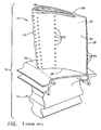
- Airfoil 12 preferably includes a generally concave pressure sidewall 20 and an opposite, generally convex, suction sidewall 22 extending between opposite leading and trailing edges 24 and 26, respectively. Sidewalls 20 and 22 also extend in the radial direction between a root 26 at platform 18 and an outer tip 28, and are spaced apart over the entire span of airfoil 12 to define at least one internal flow channel 30, see FIG. 3 , for channeling cooling air through the airfoil 12.
- the cooling air is typically bled from compressor (not shown) in any conventional manner.
- airfoil 12 may have any configuration including, for example, serpentine flow channels with various turbulators formed therein for improving cooling air effectiveness, with the cooling air being discharged through film cooling holes 32 and trailing edge discharge holes 34.
- tip 28 preferably includes a tip cap 36 integrally formed atop the radially outer ends of the pressure and suction sidewalls 20, 22, respectively, where the tip cap 36 bounds internal flow channel 30.
- a first tip rib 38 preferably extends radially outwardly from tip cap 36 between the leading and trailing edges of the pressure sidewall 20.
- a second tip rib 40 extends radially outwardly from tip cap 36 adjacent suction sidewall 22.
- the first tip rib 38 is recessed from the pressure sidewall 20 to form a tip shelf 42 substantially parallel to tip cap 36 as in accordance with the prior art to improve cooling of tip 28.
- a pocket 44 is formed between the first tip rib 38 and tip shelf 42 which promotes a recirculation of combustion gases.
- a plurality of cooling holes 46 are preferably provided along the length of tip shelf 42 to provide a cooling film recirculation zone to assist in maintaining a cooling film near first tip rib 38.
- the first tip rib 38 is inclined with respect to the radial axis of the blade, and a longitudinal axis of the second tip rib 40 may be substantially parallel to the first tip rib 38, or may be substantially parallel to the radial axis of the blade 10.
- the above-described structure is generally referred to as a "squealer tip.” Further aspects and details of the blade 10 and its alternative embodiments are found in U.S. Patent No. 6,672,829 .
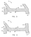
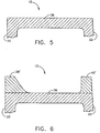
- the damaged or worn portions of the tip 28 are ground off by conventional means and the remaining tip cap 36 is dressed and otherwise prepared to receive additional material.
- material to form new first and second tip ribs 38', 40' is welded to the tip cap 36 to form a blank from which the new blade tip 28' will be constructed.
- the material used to form the tip ribs 38', 40' may be the same alloy material as the airfoil 12, or an improved alloy. Brazing may also be considered an alternative to welding.
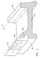
- the rebuild method continues by utilizing short, wedge-shaped electrodes "E" in spaced-apart relation along the length of the tip rib 38' of the airfoil 12, as shown in FIG. 7 .
- notches 50A-50H see FIGS. 8 and 10 , are formed in the first tip rib 38' at the intersection of the tip rib 38' and the tip cap 36.
- FIG. 10 further illustrates that the notches 50A-50H define respective tip shelves 52A-52H.
- cooling holes 54 are drilled from the tip shelves 52A-52H through the tip cap 36 and into communication with the hollow interior of the airfoil 12. Note that the holes 54 are preferably parallel to the back wall of the notches 50A-50H.
- the resulting rebuilt blade 60 has an airfoil 12' with a squealer tip 28' with several discrete tip shelves 52A-52H as distinct from the continuous tip shelf 42 provided on the blade 10 shown in Figure 1 .
- the walls of the notches 50 may be planar or nonplanar, and the vertical sidewalls may diverge radially.
- the rebuild method described above, and the resulting rebuilt blade 10 have a number of advantages.
- the EDM process itself is well-known and simple to implement.
- Each EDM electrode “E” is short and therefore well adapted to being fitted into alignment with the surface curvature of the airfoil 12'.
- the total cooling surface area inside the notches 50A-50H is greater than the corresponding cooling surface area inside the continuous tip shelf 42 of the airfoil 12 shown in FIG. 1 .
- the overall cooling efficiency is thereby improved without any countervailing disadvantages.
- the inclined back wall in each of the notches 50A-50H has the similar effect as the continuous inclined squealer tip in reducing tip leakage flow.
- notches 50A-50H are discrete and thus form a non-continuous squealer, the majority of the leakage flow reduction is maintained.
- the method described above can also be used in the casting of the original blade 10 as an alternate to the cast-in inclined squealer tip.
Landscapes
- Engineering & Computer Science (AREA)
- Mechanical Engineering (AREA)
- General Engineering & Computer Science (AREA)
- Turbine Rotor Nozzle Sealing (AREA)
Claims (10)
- Verfahren zum Wiederherstellen einer Turbinenschaufel für ein Gasturbinentriebwerk (10), wobei die Schaufel (10) von der Art ist, die ein Schaufelblatt (12) mit ersten und zweiten in Abstand angeordneten Seitenwänden (20, 22) enthält, die einen Innenhohlraum (30) definieren und an einer Vorderkante (24) und an einer Hinterkante (26) miteinander verbunden sind, wobei sich die ersten und zweiten Seitenwände (20, 22) von einem Fuß (27) aus zu einer Spitzenkappe (36) zur Führung von Verbrennungsgasen darüber erstrecken, und eine Reibspitze (28), die wenigstens eine sich von der Spitzenkappe (36) nach außen gerichtet erstreckende Spitzenrippe (38) enthält, wobei das Verfahren die Schritte aufweist:(a) Entfernen der Reibspitze (28) einschließlich der wenigstens einen Spitzenrippe (38) von der Spitzenkappe (36);(b) Hinzufügen von neuem Material zu der Spitzenkappe (36), um als eine neue Reibspitze (28') zu dienen;
gekennzeichnet durch:(c) Ausbilden mehrerer in Abstand angeordneter Aussparungen (50A bis 50H) in dem neuen Material zwischen der Vorderkante und der Hinterkante (24, 26) des Schaufelblattes (12), wobei jede Aussparung (50A bis 50H) einen entsprechenden Spitzenboden (52A bis 52H) und eine schräge Rückwand enthält; und(d) Ausbilden wenigstens eines Loches (54) in jedem Spitzenboden (52A bis 52H), das mit dem Innenhohlraum (30) des Schaufelblattes (12) in Verbindung steht, um Kühlluft aus dem Innenhohlraum (30) des Schaufelblattes (12) zu führen, um dadurch eine Reibspitze (28') auszubilden. - Verfahren nach Anspruch 1, wobei der Schritt der Entfernung der Reibspitze (28) von dem Schaufelblatt (12) den Schritt des Abschleifens der Reibspitze (28) von dem Schaufelblatt (12) umfasst.
- Verfahren nach Anspruch 1, wobei der Schritt der Hinzufügung von neuem Material zu der Spitzenkappe (36), um als eine neue Reibspitze (28') zu dienen, den Schritt der Aufschweißung wenigstens eines Metallrohlings auf die Spitzenkappe (36) umfasst.
- Verfahren nach Anspruch 1, wobei der Schritt der Ausbildung mehrerer in Abstand angeordneter Aussparungen (50A bis 50H) in dem neuen Material zwischen der Vorderkante (24) und der Hinterkante (26) des Schaufelblattes (12) die Schritte umfasst:(a) Bereitstellen von EDM-Elektroden mit einer vorbestimmten Form, die zur Ausbildung der Aussparungen (50A bis 50H) geeignet ist;(b) Anwenden der EDM-Elektroden auf vorbestimme Positionen des Schaufelblattes (12); und(c) Verwenden der EDM-Elektroden, um die Aussparungen (50A bis 50H) mittels elektrischer Entladung in das neue Material zu erodieren.
- Verfahren nach Anspruch 1, wobei der Schritt der Ausbildung wenigstens eines Loches (54) in jeder Aussparung (50A bis 50H) den Schritt des Bohrens des Loches (54) umfasst.
- Verfahren nach Anspruch 1, wobei der Schritt der Ausbildung des wenigstens einen Loches (54) den Schritt des Bohrens mehrerer Löcher (54) in jeder Aussparung (50A bis 50H) umfasst.
- Verfahren nach Anspruch 1, wobei der Schritt der Ausbildung mehrerer in Abstand angeordneter Aussparungen (50A bis 50H) in dem neuen Material die Schritte umfasst:(a) Bereitstellen von EDM-Elektroden mit einer vorbestimmten Form, die zur Ausbildung der Aussparungen (50A bis 50H) geeignet ist;(b) Anwenden der EDM-Elektroden auf das neue Material in einer beabstandeten sich in Längsrichtung erstreckenden Anordnung zwischen der Vorderkante (24) und der Hinterkante (26) des Schaufelblattes (12) und unmittelbar an seiner Oberkante (28); und(c) Verwenden der EDM-Elektroden, um die Aussparungen (50A bis 50H) mittels elektrischer Entladung in das neue Material zu erodieren.
- Verfahren zum Herstellen einer Turbinenschaufel für ein Gasturbinentriebwerk (10), wobei die Schaufel (10) von der Art ist, die ein Schaufelblatt (12) mit in Abstand angeordneten Druck- und Saugseitenwänden (20, 22) enthält, die einen Innenhohlraum (30) definieren und an einer Vorderkante (24) und an einer Hinterkante (26) miteinander verbunden sind, wobei sich die Druck- und Saugseitenwände (20, 22) von einem Fuß (27) aus zu einer Spitzenkappe (36) zur Führung von Verbrennungsgasen darüber erstrecken, und eine Reibspitze (28), die sich von der Spitzenkappe (36) nach außen gerichtet erstreckt, wobei das Verfahren die Schritte aufweist:(a) Gießen der Schaufel (10), einschließlich des Schaufelblattes (11); gekennzeichnet durch:(b) Ausbilden mehrerer in Abstand angeordneter Aussparungen (50A bis 50H) in dem Schaufelblatt unmittelbar an der Spitze (28) auf der Druckseitenwand (20), wobei jede Aussparung (50A bis 50H) einen entsprechenden Spitzenboden (52A bis 52H) und eine schräge Rückwand enthält; und(c) Ausbilden wenigstens eines Loches (54) in jedem Spitzenboden (52A bis 52H), das mit dem Innenhohlraum (30) des Schaufelblattes (12) in Verbindung steht, um Kühlluft aus dem Innenhohlraum (30) des Schaufelblattes (12) zu führen, um dadurch eine Reibspitze (28) auszubilden.
- Verfahren nach Anspruch 8, wobei der Schritt der Ausbildung mehrerer in Abstand angeordneter Aussparungen (50A bis 50H) die Schritte umfasst:(a) Bereitstellen von EDM-Elektroden mit einer vorbestimmten Form, die zur Ausbildung der Aussparungen (50A bis 50H) geeignet ist;(b) Anwenden der EDM-Elektroden auf vorbestimme Positionen des Schaufelblattes (12); und(c) Verwenden der EDM-Elektroden, um die Aussparungen (50A bis 50H) mittels elektrischer Entladung in das Schaufelblatt (12) zu erodieren.
- Verfahren nach Anspruch 8, wobei der Schritt der Erzeugung wenigstens eines Loches (54) in jeder Aussparung (50A bis 50H) den Schritt des Bohrens des Loches (54) umfasst.
Applications Claiming Priority (1)
| Application Number | Priority Date | Filing Date | Title |
|---|---|---|---|
| US10/970,031 US7270514B2 (en) | 2004-10-21 | 2004-10-21 | Turbine blade tip squealer and rebuild method |
Publications (3)
| Publication Number | Publication Date |
|---|---|
| EP1650404A2 EP1650404A2 (de) | 2006-04-26 |
| EP1650404A3 EP1650404A3 (de) | 2010-06-02 |
| EP1650404B1 true EP1650404B1 (de) | 2011-07-13 |
Family
ID=35708423
Family Applications (1)
| Application Number | Title | Priority Date | Filing Date |
|---|---|---|---|
| EP05256426A Expired - Lifetime EP1650404B1 (de) | 2004-10-21 | 2005-10-17 | Wiederherstellungsverfahren einer Turbinenschaufelspitze |
Country Status (6)
| Country | Link |
|---|---|
| US (3) | US7270514B2 (de) |
| EP (1) | EP1650404B1 (de) |
| JP (1) | JP4766983B2 (de) |
| BR (1) | BRPI0504721A (de) |
| CA (1) | CA2523255C (de) |
| SG (1) | SG122007A1 (de) |
Families Citing this family (58)
| Publication number | Priority date | Publication date | Assignee | Title |
|---|---|---|---|---|
| US7281894B2 (en) * | 2005-09-09 | 2007-10-16 | General Electric Company | Turbine airfoil curved squealer tip with tip shelf |
| US7473073B1 (en) * | 2006-06-14 | 2009-01-06 | Florida Turbine Technologies, Inc. | Turbine blade with cooled tip rail |
| US8512003B2 (en) * | 2006-08-21 | 2013-08-20 | General Electric Company | Tip ramp turbine blade |
| FR2907157A1 (fr) | 2006-10-13 | 2008-04-18 | Snecma Sa | Aube mobile de turbomachine |
| US7704045B1 (en) * | 2007-05-02 | 2010-04-27 | Florida Turbine Technologies, Inc. | Turbine blade with blade tip cooling notches |
| US7740445B1 (en) * | 2007-06-21 | 2010-06-22 | Florida Turbine Technologies, Inc. | Turbine blade with near wall cooling |
| US7845908B1 (en) | 2007-11-19 | 2010-12-07 | Florida Turbine Technologies, Inc. | Turbine blade with serpentine flow tip rail cooling |
| US8016562B2 (en) * | 2007-11-20 | 2011-09-13 | Siemens Energy, Inc. | Turbine blade tip cooling system |
| US8815371B2 (en) * | 2008-09-22 | 2014-08-26 | Siemens Energy, Inc. | Structure and method for forming detailed channels for thin walled components using thermal spraying |
| US8092178B2 (en) * | 2008-11-28 | 2012-01-10 | Pratt & Whitney Canada Corp. | Turbine blade for a gas turbine engine |
| US8092179B2 (en) * | 2009-03-12 | 2012-01-10 | United Technologies Corporation | Blade tip cooling groove |
| US8157505B2 (en) * | 2009-05-12 | 2012-04-17 | Siemens Energy, Inc. | Turbine blade with single tip rail with a mid-positioned deflector portion |
| US8172507B2 (en) * | 2009-05-12 | 2012-05-08 | Siemens Energy, Inc. | Gas turbine blade with double impingement cooled single suction side tip rail |
| US8182221B1 (en) * | 2009-07-29 | 2012-05-22 | Florida Turbine Technologies, Inc. | Turbine blade with tip sealing and cooling |
| US9890647B2 (en) * | 2009-12-29 | 2018-02-13 | Rolls-Royce North American Technologies Inc. | Composite gas turbine engine component |
| US8562286B2 (en) | 2010-04-06 | 2013-10-22 | United Technologies Corporation | Dead ended bulbed rib geometry for a gas turbine engine |
| GB201006451D0 (en) * | 2010-04-19 | 2010-06-02 | Rolls Royce Plc | Blades |
| JP5636774B2 (ja) * | 2010-07-09 | 2014-12-10 | 株式会社Ihi | タービン翼及びエンジン部品 |
| US8777567B2 (en) | 2010-09-22 | 2014-07-15 | Honeywell International Inc. | Turbine blades, turbine assemblies, and methods of manufacturing turbine blades |
| US9085988B2 (en) | 2010-12-24 | 2015-07-21 | Rolls-Royce North American Technologies, Inc. | Gas turbine engine flow path member |
| US8684691B2 (en) | 2011-05-03 | 2014-04-01 | Siemens Energy, Inc. | Turbine blade with chamfered squealer tip and convective cooling holes |
| US20130104397A1 (en) * | 2011-10-28 | 2013-05-02 | General Electric Company | Methods for repairing turbine blade tips |
| US9057271B2 (en) * | 2011-11-04 | 2015-06-16 | Siemens Energy, Inc. | Splice insert repair for superalloy turbine blades |
| US8408446B1 (en) | 2012-02-13 | 2013-04-02 | Honeywell International Inc. | Methods and tooling assemblies for the manufacture of metallurgically-consolidated turbine engine components |
| US9091177B2 (en) * | 2012-03-14 | 2015-07-28 | United Technologies Corporation | Shark-bite tip shelf cooling configuration |
| US9033670B2 (en) | 2012-04-11 | 2015-05-19 | Honeywell International Inc. | Axially-split radial turbines and methods for the manufacture thereof |
| US9115586B2 (en) | 2012-04-19 | 2015-08-25 | Honeywell International Inc. | Axially-split radial turbine |
| US20130302166A1 (en) * | 2012-05-09 | 2013-11-14 | Ching-Pang Lee | Turbine blade with chamfered squealer tip formed from multiple components and convective cooling holes |
| US9273561B2 (en) * | 2012-08-03 | 2016-03-01 | General Electric Company | Cooling structures for turbine rotor blade tips |
| US10408066B2 (en) | 2012-08-15 | 2019-09-10 | United Technologies Corporation | Suction side turbine blade tip cooling |
| CN102943694B (zh) * | 2012-12-05 | 2015-02-18 | 沈阳航空航天大学 | 动叶叶顶隔板式迷宫结构 |
| GB201223193D0 (en) * | 2012-12-21 | 2013-02-06 | Rolls Royce Plc | Turbine blade |
| US9453419B2 (en) | 2012-12-28 | 2016-09-27 | United Technologies Corporation | Gas turbine engine turbine blade tip cooling |
| US8920124B2 (en) | 2013-02-14 | 2014-12-30 | Siemens Energy, Inc. | Turbine blade with contoured chamfered squealer tip |
| US9719357B2 (en) | 2013-03-13 | 2017-08-01 | Rolls-Royce Corporation | Trenched cooling hole arrangement for a ceramic matrix composite vane |
| US9476305B2 (en) | 2013-05-13 | 2016-10-25 | Honeywell International Inc. | Impingement-cooled turbine rotor |
| US9856739B2 (en) | 2013-09-18 | 2018-01-02 | Honeywell International Inc. | Turbine blades with tip portions having converging cooling holes |
| US9816389B2 (en) | 2013-10-16 | 2017-11-14 | Honeywell International Inc. | Turbine rotor blades with tip portion parapet wall cavities |
| US9879544B2 (en) | 2013-10-16 | 2018-01-30 | Honeywell International Inc. | Turbine rotor blades with improved tip portion cooling holes |
| EP3068975B1 (de) * | 2013-11-11 | 2020-11-25 | United Technologies Corporation | Bauteil eines gasturbinentriebwerks und zugehörige herstellungsverfahren |
| US10041358B2 (en) | 2014-05-08 | 2018-08-07 | United Technologies Corporation | Gas turbine engine blade squealer pockets |
| US10376998B2 (en) * | 2014-07-03 | 2019-08-13 | United Technologies Corporation | Methods and tools for use in repairing gas engine turbine blades |
| US10107108B2 (en) | 2015-04-29 | 2018-10-23 | General Electric Company | Rotor blade having a flared tip |
| US10053992B2 (en) | 2015-07-02 | 2018-08-21 | United Technologies Corporation | Gas turbine engine airfoil squealer pocket cooling hole configuration |
| US10227876B2 (en) * | 2015-12-07 | 2019-03-12 | General Electric Company | Fillet optimization for turbine airfoil |
| DE102016224632A1 (de) * | 2016-12-09 | 2018-06-14 | Rolls-Royce Deutschland Ltd & Co Kg | Plattenförmiges Bauteil einer Gasturbine sowie Verfahren zu dessen Herstellung |
| US10830082B2 (en) * | 2017-05-10 | 2020-11-10 | General Electric Company | Systems including rotor blade tips and circumferentially grooved shrouds |
| US10995619B2 (en) * | 2017-05-26 | 2021-05-04 | General Electric Company | Airfoil and method of fabricating same |
| US10774658B2 (en) | 2017-07-28 | 2020-09-15 | General Electric Company | Interior cooling configurations in turbine blades and methods of manufacture relating thereto |
| JP7012825B2 (ja) * | 2017-08-14 | 2022-01-28 | シーメンス アクティエンゲゼルシャフト | タービンブレードおよび対応する供与方法 |
| JP6979382B2 (ja) * | 2018-03-29 | 2021-12-15 | 三菱重工業株式会社 | タービン動翼、及びガスタービン |
| US10787932B2 (en) | 2018-07-13 | 2020-09-29 | Honeywell International Inc. | Turbine blade with dust tolerant cooling system |
| JP7216335B2 (ja) * | 2019-03-28 | 2023-02-01 | 株式会社Ihi | タービン動翼 |
| DE102019125779B4 (de) * | 2019-09-25 | 2024-03-21 | Man Energy Solutions Se | Schaufel einer Strömungsmaschine |
| EP4028643B1 (de) * | 2019-10-28 | 2023-12-06 | Siemens Energy Global GmbH & Co. KG | Turbinenschaufel, verfahren zur herstellung einer turbinenschaufel und verfahren zur überholung einer turbinenschaufel |
| US11299991B2 (en) * | 2020-04-16 | 2022-04-12 | General Electric Company | Tip squealer configurations |
| US12123319B2 (en) | 2020-12-30 | 2024-10-22 | Ge Infrastructure Technology Llc | Cooling circuit having a bypass conduit for a turbomachine component |
| US12186849B1 (en) | 2023-11-03 | 2025-01-07 | Ge Infrastructure Technology Llc | Method of repairing an airfoil having tip cooling passages |
Family Cites Families (20)
| Publication number | Priority date | Publication date | Assignee | Title |
|---|---|---|---|---|
| US4390320A (en) * | 1980-05-01 | 1983-06-28 | General Electric Company | Tip cap for a rotor blade and method of replacement |
| MX155481A (es) * | 1981-09-02 | 1988-03-17 | Westinghouse Electric Corp | Pala de rotor de turbina |
| JPS62223402A (ja) * | 1986-03-24 | 1987-10-01 | Toshiba Corp | タ−ビン動翼の先端冷却構造 |
| US5261789A (en) | 1992-08-25 | 1993-11-16 | General Electric Company | Tip cooled blade |
| US5584663A (en) * | 1994-08-15 | 1996-12-17 | General Electric Company | Environmentally-resistant turbine blade tip |
| US5733102A (en) * | 1996-12-17 | 1998-03-31 | General Electric Company | Slot cooled blade tip |
| US5822852A (en) * | 1997-07-14 | 1998-10-20 | General Electric Company | Method for replacing blade tips of directionally solidified and single crystal turbine blades |
| US6059530A (en) * | 1998-12-21 | 2000-05-09 | General Electric Company | Twin rib turbine blade |
| US6190129B1 (en) * | 1998-12-21 | 2001-02-20 | General Electric Company | Tapered tip-rib turbine blade |
| US6179556B1 (en) | 1999-06-01 | 2001-01-30 | General Electric Company | Turbine blade tip with offset squealer |
| US6422821B1 (en) * | 2001-01-09 | 2002-07-23 | General Electric Company | Method and apparatus for reducing turbine blade tip temperatures |
| US6382913B1 (en) * | 2001-02-09 | 2002-05-07 | General Electric Company | Method and apparatus for reducing turbine blade tip region temperatures |
| US6554575B2 (en) * | 2001-09-27 | 2003-04-29 | General Electric Company | Ramped tip shelf blade |
| US6908288B2 (en) * | 2001-10-31 | 2005-06-21 | General Electric Company | Repair of advanced gas turbine blades |
| US6672829B1 (en) * | 2002-07-16 | 2004-01-06 | General Electric Company | Turbine blade having angled squealer tip |
| US6790005B2 (en) * | 2002-12-30 | 2004-09-14 | General Electric Company | Compound tip notched blade |
| US6971851B2 (en) * | 2003-03-12 | 2005-12-06 | Florida Turbine Technologies, Inc. | Multi-metered film cooled blade tip |
| US6991430B2 (en) * | 2003-04-07 | 2006-01-31 | General Electric Company | Turbine blade with recessed squealer tip and shelf |
| US20050091848A1 (en) * | 2003-11-03 | 2005-05-05 | Nenov Krassimir P. | Turbine blade and a method of manufacturing and repairing a turbine blade |
| US20060218788A1 (en) * | 2005-03-30 | 2006-10-05 | Snecma Services | Method of manufacturing a hollow blade that includes a recessed tip cap and method of reparing such a blade |
-
2004
- 2004-10-21 US US10/970,031 patent/US7270514B2/en not_active Expired - Fee Related
-
2005
- 2005-10-07 BR BRPI0504721-8A patent/BRPI0504721A/pt not_active IP Right Cessation
- 2005-10-13 CA CA2523255A patent/CA2523255C/en not_active Expired - Fee Related
- 2005-10-17 JP JP2005301213A patent/JP4766983B2/ja not_active Expired - Fee Related
- 2005-10-17 EP EP05256426A patent/EP1650404B1/de not_active Expired - Lifetime
- 2005-10-20 SG SG200506805A patent/SG122007A1/en unknown
-
2007
- 2007-06-21 US US11/766,488 patent/US7591070B2/en not_active Expired - Fee Related
- 2007-06-21 US US11/766,509 patent/US7584538B2/en not_active Expired - Fee Related
Also Published As
| Publication number | Publication date |
|---|---|
| EP1650404A2 (de) | 2006-04-26 |
| US20080060197A1 (en) | 2008-03-13 |
| US7591070B2 (en) | 2009-09-22 |
| JP2006118503A (ja) | 2006-05-11 |
| EP1650404A3 (de) | 2010-06-02 |
| SG122007A1 (en) | 2006-05-26 |
| US20070277361A1 (en) | 2007-12-06 |
| US7584538B2 (en) | 2009-09-08 |
| US7270514B2 (en) | 2007-09-18 |
| CA2523255A1 (en) | 2006-04-21 |
| BRPI0504721A (pt) | 2006-06-06 |
| CA2523255C (en) | 2013-09-10 |
| US20060088420A1 (en) | 2006-04-27 |
| JP4766983B2 (ja) | 2011-09-07 |
Similar Documents
| Publication | Publication Date | Title |
|---|---|---|
| EP1650404B1 (de) | Wiederherstellungsverfahren einer Turbinenschaufelspitze | |
| US8083484B2 (en) | Turbine rotor blade tips that discourage cross-flow | |
| EP1057970B1 (de) | Schaufelspitze mit Prallkühlung | |
| EP1529153B1 (de) | Turbinenschaufel mit einer geneigten rippe an der spitze | |
| US7575414B2 (en) | Turbine nozzle with trailing edge convection and film cooling | |
| EP1013878B1 (de) | Turbinenschaufel mit Doppel-Endrippe | |
| US6595749B2 (en) | Turbine airfoil and method for manufacture and repair thereof | |
| US6955522B2 (en) | Method and apparatus for cooling an airfoil | |
| US7118342B2 (en) | Fluted tip turbine blade | |
| US6190129B1 (en) | Tapered tip-rib turbine blade | |
| EP1760267B1 (de) | Turbinenrotorschaufel | |
| EP1057972A2 (de) | Versetzte Blattspitzenabdichtung für eine Turbinenschaufel | |
| EP1586739A2 (de) | Hitzeschild für eine Gasturbinen-Schaufel | |
| EP1614860B1 (de) | Turbinenschaufel mit eingerückter Schaufelspitze | |
| EP1764477B1 (de) | Turbineschaufel mit kannelierter Spitze |
Legal Events
| Date | Code | Title | Description |
|---|---|---|---|
| PUAI | Public reference made under article 153(3) epc to a published international application that has entered the european phase |
Free format text: ORIGINAL CODE: 0009012 |
|
| AK | Designated contracting states |
Kind code of ref document: A2 Designated state(s): AT BE BG CH CY CZ DE DK EE ES FI FR GB GR HU IE IS IT LI LT LU LV MC NL PL PT RO SE SI SK TR |
|
| AX | Request for extension of the european patent |
Extension state: AL BA HR MK YU |
|
| PUAL | Search report despatched |
Free format text: ORIGINAL CODE: 0009013 |
|
| AK | Designated contracting states |
Kind code of ref document: A3 Designated state(s): AT BE BG CH CY CZ DE DK EE ES FI FR GB GR HU IE IS IT LI LT LU LV MC NL PL PT RO SE SI SK TR |
|
| AX | Request for extension of the european patent |
Extension state: AL BA HR MK YU |
|
| 17P | Request for examination filed |
Effective date: 20101202 |
|
| GRAP | Despatch of communication of intention to grant a patent |
Free format text: ORIGINAL CODE: EPIDOSNIGR1 |
|
| AKX | Designation fees paid |
Designated state(s): DE FR GB |
|
| RIC1 | Information provided on ipc code assigned before grant |
Ipc: F01D 5/00 20060101AFI20110107BHEP Ipc: F01D 5/14 20060101ALI20110107BHEP Ipc: F01D 5/18 20060101ALI20110107BHEP |
|
| GRAS | Grant fee paid |
Free format text: ORIGINAL CODE: EPIDOSNIGR3 |
|
| GRAA | (expected) grant |
Free format text: ORIGINAL CODE: 0009210 |
|
| AK | Designated contracting states |
Kind code of ref document: B1 Designated state(s): DE FR GB |
|
| REG | Reference to a national code |
Ref country code: GB Ref legal event code: FG4D |
|
| REG | Reference to a national code |
Ref country code: DE Ref legal event code: R096 Ref document number: 602005028957 Country of ref document: DE Effective date: 20110908 |
|
| PLBE | No opposition filed within time limit |
Free format text: ORIGINAL CODE: 0009261 |
|
| STAA | Information on the status of an ep patent application or granted ep patent |
Free format text: STATUS: NO OPPOSITION FILED WITHIN TIME LIMIT |
|
| 26N | No opposition filed |
Effective date: 20120416 |
|
| REG | Reference to a national code |
Ref country code: DE Ref legal event code: R097 Ref document number: 602005028957 Country of ref document: DE Effective date: 20120416 |
|
| PGFP | Annual fee paid to national office [announced via postgrant information from national office to epo] |
Ref country code: DE Payment date: 20141029 Year of fee payment: 10 Ref country code: GB Payment date: 20141027 Year of fee payment: 10 Ref country code: FR Payment date: 20141017 Year of fee payment: 10 |
|
| REG | Reference to a national code |
Ref country code: DE Ref legal event code: R119 Ref document number: 602005028957 Country of ref document: DE |
|
| GBPC | Gb: european patent ceased through non-payment of renewal fee |
Effective date: 20151017 |
|
| PG25 | Lapsed in a contracting state [announced via postgrant information from national office to epo] |
Ref country code: GB Free format text: LAPSE BECAUSE OF NON-PAYMENT OF DUE FEES Effective date: 20151017 Ref country code: DE Free format text: LAPSE BECAUSE OF NON-PAYMENT OF DUE FEES Effective date: 20160503 |
|
| REG | Reference to a national code |
Ref country code: FR Ref legal event code: ST Effective date: 20160630 |
|
| PG25 | Lapsed in a contracting state [announced via postgrant information from national office to epo] |
Ref country code: FR Free format text: LAPSE BECAUSE OF NON-PAYMENT OF DUE FEES Effective date: 20151102 |