EP1650334A2 - Electric shedding apparatus for loom - Google Patents
Electric shedding apparatus for loom Download PDFInfo
- Publication number
- EP1650334A2 EP1650334A2 EP05021461A EP05021461A EP1650334A2 EP 1650334 A2 EP1650334 A2 EP 1650334A2 EP 05021461 A EP05021461 A EP 05021461A EP 05021461 A EP05021461 A EP 05021461A EP 1650334 A2 EP1650334 A2 EP 1650334A2
- Authority
- EP
- European Patent Office
- Prior art keywords
- shedding
- shedding motion
- motion condition
- load
- recommended
- Prior art date
- Legal status (The legal status is an assumption and is not a legal conclusion. Google has not performed a legal analysis and makes no representation as to the accuracy of the status listed.)
- Withdrawn
Links
- 239000004744 fabric Substances 0.000 description 10
- 230000006870 function Effects 0.000 description 7
- 238000009941 weaving Methods 0.000 description 7
- 238000010586 diagram Methods 0.000 description 6
- 238000000034 method Methods 0.000 description 6
- 239000000284 extract Substances 0.000 description 2
- 230000007246 mechanism Effects 0.000 description 2
- 230000006386 memory function Effects 0.000 description 2
- 239000007787 solid Substances 0.000 description 2
- 230000005856 abnormality Effects 0.000 description 1
- 230000007257 malfunction Effects 0.000 description 1
Images

Classifications
-
- D—TEXTILES; PAPER
- D03—WEAVING
- D03D—WOVEN FABRICS; METHODS OF WEAVING; LOOMS
- D03D51/00—Driving, starting, or stopping arrangements; Automatic stop motions
-
- D—TEXTILES; PAPER
- D03—WEAVING
- D03C—SHEDDING MECHANISMS; PATTERN CARDS OR CHAINS; PUNCHING OF CARDS; DESIGNING PATTERNS
- D03C13/00—Shedding mechanisms not otherwise provided for
-
- D—TEXTILES; PAPER
- D03—WEAVING
- D03C—SHEDDING MECHANISMS; PATTERN CARDS OR CHAINS; PUNCHING OF CARDS; DESIGNING PATTERNS
- D03C13/00—Shedding mechanisms not otherwise provided for
- D03C13/02—Shedding mechanisms not otherwise provided for with independent drive motors
- D03C13/025—Shedding mechanisms not otherwise provided for with independent drive motors with independent frame drives
-
- D—TEXTILES; PAPER
- D03—WEAVING
- D03J—AUXILIARY WEAVING APPARATUS; WEAVERS' TOOLS; SHUTTLES
- D03J1/00—Auxiliary apparatus combined with or associated with looms
- D03J1/005—Displays or displaying data
Definitions
- the present invention relates to a device for setting a shedding motion condition for an electric shedding apparatus that drives multiple heald frames with dedicated motors.
- a typical electric shedding apparatus for a loom multiple heald frames are driven by dedicated motors on the basis of predetermined shedding curves.
- Each shedding curve is defined by a rotational angle of a loom main shaft that corresponds to a middle position in the vertical movement of the corresponding heald frame (hereafter called a middle position) and a dwell (stop angle) at an uppermost or lowermost shed position.
- a middle position a middle position in the vertical movement of the corresponding heald frame
- a dwell stop angle
- An object of the present invention is to allow an operator to determine whether or not input values regarding the shedding motion are adequate, thereby causing the operator to set adequate shedding motion conditions.
- the electric shedding apparatus may further include a display unit for displaying the determined load.
- the display unit may display the set shedding motion condition in the form of a graph of a shedding curve together with the determined load.
- the display unit may display a plurality of shedding motion conditions that are close to the set shedding motion condition and that correspond to loads lower than the load corresponding to the set shedding motion condition together with the loads corresponding to said plurality of shedding motion conditions.
- the electric shedding apparatus may further include a display unit, and the calculator may determine a recommended shedding motion condition corresponding to a load lower than an allowable value on the basis of the set shedding motion condition, the database, and the allowable load.
- the display unit displays the recommended shedding motion condition.
- the display unit may display the recommended shedding motion condition in the form of numerical values or a graph of a shedding curve.
- the display unit may display a plurality of shedding motion conditions that are close to the set shedding motion condition and that correspond to loads lower than the allowable value together with the loads corresponding to said plurality of shedding motion conditions.
- the calculator may determine a recommended shedding motion condition corresponding to a load lower than an allowable value on the basis of the set shedding motion condition, the database, the allowable load, and output the recommended shedding motion condition to the controller.
- the load is determined on the basis of the set shedding motion condition and the database. Therefore, the operator can easily perform the adjustment the loom taking the load applied to each motor into account without test weaving.
- the operator recognizes whether or not the input shedding motion condition is adequate.
- the operator easily recognizes whether or not the set shedding motion condition is adequate from the graph.
- the operator can set a recommended shedding motion condition selected from among the shedding motion conditions under which the loads do not exceed the load corresponding to the set shedding motion condition.
- the recommended shedding motion condition can be set directly using the displayed numerical values.
- the recommended shedding motion condition is displayed in the form of a graph of a shedding curve, the shedding curve based on the recommended shedding motion condition can be visually recognized.
- the operator can set a recommended shedding motion condition selected from among the shedding motion conditions under which the loads do not exceed the allowable load.
- the recommended shedding motion condition can be set automatically.
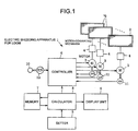
- Fig. 1 illustrates an electric shedding apparatus 1 for a loom according to the present invention.
- the electric shedding apparatus 1 includes multiple heald frames 2, dedicated motors 3 for driving the respective heald frames 2, and motion-converting mechanisms 4.
- Each motor 3 is constituted of a servo motor, and the rotation of each motor 3 is converted into a vertical reciprocating motion of the corresponding heald frame 2 by the corresponding motion-converting mechanism 4.
- the shedding motion of the heald frames 2 is performed.
- the electric shedding apparatus 1 also includes a setter 5, a controller 6, a memory 7, a calculator 8, and a display unit 9 in order to control the motors 3.
- Each of the setter 5, the controller 6, the memory 7, the calculator 8, and the display unit 9 may be structured as an individual device with a single function. Alternatively, they may also be structured as a single unit with a program using an input/output function, a memory function, and a calculating function of an industrial computer.
- the setter 5 includes an input unit, such as a keyboard and a touch panel, for setting a shedding motion condition including a plurality of items for driving each heald frame 2.
- the controller 6 detects a rotational angle of a loom main shaft 10 on the basis of a rotational-angle signal obtained from an encoder 12 connected to the loom main shaft 10, and controls the rotation of the motors 3 on the basis of the shedding motion conditions set for the heald frames 2 in synchronization with the detected rotational angle.
- the actual rotation of each motor 3 is detected by a corresponding encoder 11, and is fed back to the controller 6.
- the memory 7 stores a database including a plurality of shedding motion conditions and the actual loads placed on the motors 3 when the heald frames 2 are driven under those shedding motion conditions.
- the calculator 8 basically determines a load on each motor 3 that corresponds to a set shedding motion condition on the basis of the set shedding motion condition and the database.
- the display unit 9 basically displays the determined load.
- the detailed functions of the calculator 8 and the display unit 9 slightly differ in each embodiment.
- the items of the shedding motion condition include a middle position between top and bottom dead centers, a shed size, a cloth width, a structure (shedding pattern), a loom rotational speed, and a dwell.
- the calculator 8 determines the load on each motor 3 that corresponds to the set shedding motion condition on the basis of the set shedding motion condition and the database. In addition to the determination of the load corresponding to the set shedding motion condition, in a second embodiment, the calculator 8 also determines a recommended shedding motion condition under which the load placed on the motor 3 is lower than an allowable value thereof on the basis of the set shedding motion condition, the database, and the allowable value of the load. In a third embodiment, the calculator 8 also determines a recommended shedding motion condition under which the load placed on the motor 3 is within an allowable range thereof on the basis of the set shedding motion condition, the database, and the allowable value of the load. The determined load and the recommended shedding motion condition are output to the display unit 9 and the controller 6.
- the display unit 9 displays the determined load and additionally displays the set shedding motion condition in the form of a graph (shedding curve) as necessary.
- the display unit 9 displays the recommended shedding motion condition.
- the recommended shedding motion condition is displayed in the form of either numerical values or a graph (shedding curve).
- the display unit 9 may also be omitted.
- the shedding curve shows a variation in the vertical position of the corresponding heald frame 2 versus rotational angle of the loom main shaft 10.
- the shedding motion condition for each heald frame 2 is input to the setter 5, and the load placed on the corresponding motor 3 when the heald frame 2 is driven under the input shedding motion condition is determined and displayed on the display unit 9.
- the memory 7 stores a plurality of databases including a plurality of shedding motion conditions, for example, for each weave structure.
- the databases are obtained by performing an actual weaving process under various shedding motion conditions and accumulating the data of actual loads placed on the motors 3 for driving the heald frames 2.
- the databases are stored in the form of a map or a table, as shown in Fig. 2.
- the upper section shows basic items of the shedding motion condition.
- the middle position between the top and bottom dead centers (the rotational angle of the loom main shaft 10) is 300°
- the shed size is 100 mm
- the cloth width is 1900 mm
- the structure (shedding pattern) is 1/1 (plain weave).
- the lower section shows a table of other items of the shedding motion condition.
- the horizontal axis represents the loom rotational speed (rpm) in the range of 500 rpm to 900 rpm
- the vertical axis represents the dwell (rotational angle) in the range of 0°/0° to 0°/120°.
- the maximum load (%) placed on the motor 3 if the corresponding heald frame 2 is driven under each combination of the rotational speed and the dwell is shown in the table.
- the load on the motor 3 is shown in terms of a percentage when the rated output (maximum usable output) is 100%. More specifically, a load of 80%, for example, means that the motor output is 80% of the rated output.
- the dwell is shown by a fraction of the rotational angle in which the denominator shows the rotational-angle range of the loom main shaft 10 corresponding to the bottom side of the shedding curve (bottom dead center), and the numerator shows the rotational-angle range of the loom main shaft 10 corresponding to the top side of the shedding curve (top dead center).
- the percentage of the load on the motor 3 is also increased since the speed of the heald frame 2 in the open period is increased.
- the percentage of the load on the motor 3 is also increased since the moving time of the heald frame 2 in the open period is reduced and the speed of the heald frame 2 in the open period is increased accordingly.
- the operator designates a frame number of each heald frame 2 and inputs values (numerical values) for the items of the shedding motion condition to be input to the calculator 8 by operating a key or a touch input screen of the setter 5.
- the operator designates a frame number of each heald frame 2 and inputs values for the same items as those set in the database for each of the heald frames 2. For example, the operator inputs 300° for the middle position between the top and bottom dead centers (rotational angle), 100 mm for the shed size, 1900 mm for the cloth width, 1/1 (plain weave) for the structure (shedding pattern), 600 rpm for the loom rotational speed, and 0°/60° for the dwell.
- Fig. 3 is a diagram illustrating bottom positions (hatched sections) and top positions (blank sections) of eight heald frames 2 corresponding to frame numbers 1 to 8 in a single repeat (six cycles). The load on each motor 3 is increased when the opening direction is changed or when the open state is maintained.
- the angle that is 180° ahead of the rotational angle of the loom main shaft 10 at the middle position is defined as the reference rotational angle for the top dead center
- the angle that is 180° behind the rotational angle at the middle position is defined as the reference rotational angle for the bottom dead center.
- the rotational angle at the middle position is 300°
- the rotational angle of the top dead center is 120° in the same cycle as the middle position
- the rotational angle of the bottom dead center is 120° in the next cycle.
- the dwell is set in the form of, for example, 20°/60°, it is input in the manner shown at the bottom of Fig. 4 in practice. More specifically, each of the dwell periods at the top and bottom dead centers (rotational angle ranges of the loom main shaft 10 while the heald frame is at the top and bottom dead centers) are divided into the first half and the second half with respect to the reference rotational angles of the top and bottom dead centers. Accordingly, the dwell of 20°/60° is input as (10°,10°)/(30°,30°) in practice. This input means that the rotational angle ranges at the top and bottom dead centers are 10° and 30°, respectively, in the first half thereof and are also 10° and 30°, respectively, in the second half thereof. In each dwell period, the rotational angle in the first half and that in the second half may be set to different rotational angles.
- the shed size is determined mechanically or depending on the kind of yarn, and may therefore be excluded from the input items and be set in advance.
- the cloth width is also determined mechanically or depending on the kind of yarn, and may therefore be excluded from the input items and be set in advance.
- the operator inputs shedding motion conditions for all the frame numbers to the setter 5.
- the calculator 8 extracts loads corresponding to the input shedding motion conditions from the database stored in the memory 7 and outputs the display data of the loads to the display unit 9.
- the display unit 9 displays the contents corresponding to those shown in Fig. 2.
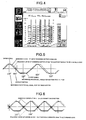
- Fig. 4 shows a display screen in which the middle position, the dwell, and the shed size are shown in numerical values. Other items of the shedding motion condition are also shown in dedicated display screens in numerical values.
- the shed size when the shed size is not input through the display screen shown in Fig. 4, the initial value that is set in advance is used. The operator can also input the shed size through the display screen shown in Fig. 4 to change the shed size. However, the change in the shed size through the display screen is reflected only on the calculation of the load, and the shed size adjustment must be performed in the electric shedding apparatus 1 in order to change the actual shed size of the heald frame 2.
- the input shedding motion condition is regarded suitable in view of the load placed on the motor 3 in the electric shedding apparatus 1.
- the load on the motor 3 is 75%, which is also within the allowable range, when the loom rotational speed is increased to 800 rpm or the dwell is changed to 0°/120° by increasing the dwell period at the bottom dead center. Accordingly, the operator changes the loom rotational speed, the dwell, etc., within the allowable range in order to set an optimum condition by taking the operational state and the weaving efficiency into account.
- the operator changes the loom rotational speed, the dwell, etc., so as to reduce the load. If the load cannot be reduced to within the allowable range by this process, the shed size, for example, is reduced.
- the priority order of the items of the shedding motion condition to be changed is: the loom rotational speed, the dwell, and the shed size. Changes in these items may lead to a change in the middle position between the top and bottom dead centers (rotational angle) .
- the calculator 8 selects the database having the shedding motion condition that is closest to the input shedding motion condition.
- the database shown in Fig. 2 in which the middle position, the shed size, the cloth width, and the structure match those of the input shedding motion condition is selected. Then, the data of the items that does not match the input items are read out from the database. In detail, two loom rotational speeds and/or two dwells that are closest to the set loom rotational speed and/or the set dwell are read out along with the corresponding loads.
- interpolation calculation is performed using the two data elements to determine the load.
- the load corresponding to the set value is obtained by interpolation calculation using two loom rotational speeds 700 rpm and 800 rpm.
- the set dwell is 0°/90°
- the load corresponding to the set value is obtained by interpolation calculation using two dwells 0°/120° and 0°/60°.
- the operator may perform the above-described interpolation calculation.
- the calculator 8 selects the database shown in Fig. 2 in which the middle position, the shed size, the cloth width, and the structure match those of the input shedding motion condition. Then, among the loom rotational speeds and the dwells included in the database, the calculator 8 displays two loom rotational speeds and/or two dwells that are closest to the set loom rotational speed and/or the set dwell along with the corresponding loads on the display unit 9. The operator checks the data shown on the display unit 9 and performs the interpolation calculation using the data.
- the database with the closest shedding motion conditions is extracted.
- the shedding motion condition in the extracted database is used as a basic shedding motion condition, and the load on the motor 3 corresponding to the input shedding motion condition is predicted by calculation using experimental coefficients.
- the case is considered in which at least one of the shed size, the cloth width, and the structure does not match in the database shown in Fig. 2 will be considered.
- the load on the motor 3 corresponding to the input shedding motion condition is predicted using the basic shedding motion condition.
- the shed size L and the cloth width S are both expressed in terms of length (mm).
- the structure M is a value intrinsic to the weave structure and is defined as the sum of the number of times the corresponding heald frame 2 rises upward from the lower dwell and the number of times it falls to the lower dwell in a single repeat of the weave structure (no unit), or as the sum of the number of times the corresponding heald frame 2 falls downward from the upper dwell and the number of times it rises to the upper dwell in a single repeat of the weave structure (no unit).
- the load can be directly obtained without performing the interpolation calculation or the prediction calculation, and therefore the load can be calculated with increased accuracy.
- the data of the shedding motion conditions may be stored in multiple memory chips, for example, one for each weave structure (shedding pattern). In this case, the memory chips may be selectively used by inserting them into the memory 7. Alternatively, the data may also be extracted from a host computer.
- the load extracted from the database or determined by the interpolation calculation or the prediction calculation on the basis of the database is displayed by the display unit 9 in, for example, the form shown in Fig. 5.
- the operator reads the load on the motor 3 and determines whether or not the input shedding motion condition is adequate. If the input shedding motion condition is not adequate, the operator changes the shedding motion condition and checks the load again until an adequate shedding motion condition is determined. Then, the weaving process is started. In the weaving process, the controller 6 controls the rotation of each motor 3 on the basis of the input adequate shedding motion condition and cause the heald frames 2 to perform the predetermined shedding motion.
- the display unit 9 may additionally display a plurality of shedding motion conditions that are close to the set shedding motion condition and that correspond to loads lower than the load corresponding to the set shedding motion condition together with the corresponding loads. For example, as shown in Fig. 2, when the loom rotational speed is 900 rpm and the dwell is 0°/120° according to the set shedding motion condition, the corresponding load is 105%. In this case, the display unit 9 displays a plurality of shedding motion conditions that are close to the set shedding motion condition and that correspond to loads of 100% or less together with the corresponding loads. In this manner, not only the load corresponding to the set shedding motion condition but also the shedding motion conditions corresponding to loads lower than the load corresponding to the set shedding motion condition are displayed. Accordingly, the operator can set a recommended shedding motion condition selected from the shedding motion conditions corresponding to loads lower than the determined load.
- the shedding curve based on the set shedding motion condition may also be displayed on the display unit 9 together with the numerical values of the set shedding motion condition or by itself.
- the allowable load on the motor 3 may be set in advance, and the determined load may be displayed in a different color, for example, red, if the determined load exceeds the allowable value.
- the allowable load on the motor 3 is also input in addition to the shedding motion condition, and a shedding motion condition under which the load on the motor 3 does not exceed the allowable value is determined on the bases of the set shedding motion condition, the database, and the allowable load.
- the thus determined shedding motion condition is displayed on the display unit 9.
- the allowable load on the motor 3, for example, 80% is input to the setter 5 through the display screen shown in Fig. 4.
- the middle position of 290° and the shed size of 120 mm are input as the shedding motion conditions for frame number 1.
- the calculator 8 extracts, from the database stored in the memory 7, a recommended shedding motion condition under which the load does not exceed the input allowable load.
- the set shedding motion condition matches a shedding motion condition in the database stored in the memory 7 and if the load extracted from the database is equal to or lower than the set allowable load, the set shedding motion condition is determined as the recommended shedding motion condition.
- the set shedding motion condition matches a shedding motion condition in the database stored in the memory 7 but the load extracted from the database is higher than the set allowable load.
- the loom rotational speed and the dwell are reduced by one rank in that priority order. Then, the load corresponding to the reduced loom rotational speed and the dwell is compared with the allowable load.
- the loom rotational speed and the dwell are repeatedly reduced, in that priority order, in steps of one rank until the corresponding load is reduced to below the input allowable load. Then, the shedding motion condition corresponding to the load below the input allowable load is determined as the recommended shedding motion condition.
- the above-described process may also be performed such that only one of the loom rotational speed and the dwell is reduced in steps of one rank.
- the closest shedding motion conditions and loads corresponding thereto are used to determine the load corresponding to the input shedding motion condition. More specifically, the load corresponding to the input shedding motion condition is determined by the interpolation calculation or the calculation using the correction coefficients a, b, and c. If the thus determined load is equal to or lower than the allowable load, the set shedding motion condition is determined as the recommended shedding motion condition. If the determined load is higher than the allowable load, the recommended shedding motion condition is determined by reducing the rank of the shedding motion condition until the corresponding load is reduced to below the allowable load.
- the allowable load may be set as a value intrinsic to the loom when the loom is shipped.
- the calculator 8 changes the items, such as the loom rotational speed and the dwell, of the shedding motion condition and determines the shedding recommended shedding motion condition including the items under which the load does not exceed the allowable value.
- the recommended shedding motion condition extracted from the database or determined by the interpolation calculation or the prediction calculation on the basis of the database is displayed on the display unit 9 as, for example, the loom rotational speed: 600 rpm, the middle position: 300°, and the dwell: (0°, 0°)/(40°, 40°).
- the display unit 9 shows the shedding curve based on the recommended shedding motion condition, as shown in Figs. 5 and 6, together with the numerical values of the recommended shedding motion condition or by itself.
- the recommended shedding motion condition is displayed in the form of the numerical values, the graph (shedding curve), or the combination of the numerical values and the graph (shedding curve) as necessary.
- a shedding curve corresponding to the input shedding motion condition (solid line), a shedding curve corresponding to the recommended shedding motion condition under which the load does not exceed the allowable load (dashed line), or both of the shedding curves (solid and dashed lines) are displayed for each of the single heald frame 2.
- the display of the shedding curve is switched using the setter 5.
- shedding curves for two heald frames 2 are shown in the graph.
- shedding curves corresponding to the input shedding motion conditions (solid lines), shedding curves corresponding to the recommended shedding motion conditions under which the loads do not exceed the allowable load (dashed lines), or both of the shedding curves (solid and dashed lines) are displayed.
- the frame numbers of the heald frames 2 whose shedding curves are to be displayed are selected by the setter 5.
- the operator changes the shedding motion condition on the basis of the recommended shedding motion condition, and sets the condition with the setter 5.
- the display unit 9 may additionally display a plurality of shedding motion conditions that are close to the set shedding motion conditions and that correspond to loads lower than the allowable load together with the corresponding loads. For example, similar to Fig. 2, when the set allowable load is 80% and the loom rotational speed and the dwell are 700 rpm and 0°/120°, respectively, according to the recommended shedding motion condition, the display unit 9 displays a plurality of shedding motion conditions that are close to the set shedding motion condition and that correspond to loads lower than 80% together with the corresponding loads.
- a table showing the shedding motion conditions in which the loom rotational speed ranges from 600 rpm to 700 rpm and the dwell ranges from 0°/60° to 0°/120° and the loads corresponding to the shedding motion conditions is displayed.
- the operator can set a shedding motion condition selected from the shedding motion conditions corresponding to loads lower than the allowable load.
- the allowable load on the motor 3 is input in addition to the shedding motion condition, and a recommended shedding motion condition under which the load does not exceed the allowable load is determined.
- the recommended shedding motion condition determined as above is output to the controller 6, and the controller 6 automatically sets the recommended shedding motion condition.
- the calculator 8 determines and outputs the recommended shedding motion condition to the controller 6, which automatically sets the recommended shedding motion condition received from the calculator 8. Accordingly, the operator's task of loom adjustment is reduced.
- the display unit 9 displays the recommended shedding motion condition in the form of the numerical values, the graph (shedding curve), or the combination of the numerical values and the graph (shedding curve). However, since the recommended shedding motion condition is automatically set by the controller 6, the display unit 9 may be omitted in the third embodiment.
- the present invention may be applied to all kinds of electric shedding apparatuses 1 for looms.
- load sensors are attached to drive circuits or rotating members of the motors 3 as necessary.
- the loom's main controller (not shown) measures the loads on the motors 3 while the loom is in operation (during weaving) and generates an abnormality signal if it is determined that the measured loads have exceeded the calculated loads due to mechanical causes. In this case, mechanical malfunction of the electric shedding apparatus 1 for the loom can be detected at an early stage, and the loom can be adequately managed.
- each of the setter 5, the controller 6, the memory 7, the calculator 8, and the display unit 9 may be structured as an individual device with a single function. Alternatively, they may also be structured as a single unit with a program using an input/output function, a memory function, and a calculating function of an industrial computer.
Landscapes
- Engineering & Computer Science (AREA)
- Textile Engineering (AREA)
- Looms (AREA)
- Control Of Multiple Motors (AREA)
Abstract
Description
- The present invention relates to a device for setting a shedding motion condition for an electric shedding apparatus that drives multiple heald frames with dedicated motors.
- In a typical electric shedding apparatus for a loom, multiple heald frames are driven by dedicated motors on the basis of predetermined shedding curves. Each shedding curve is defined by a rotational angle of a loom main shaft that corresponds to a middle position in the vertical movement of the corresponding heald frame (hereafter called a middle position) and a dwell (stop angle) at an uppermost or lowermost shed position. When the dwell and the rotational speed of the loom are not adequately set, an excessive load is placed on the motor for driving the heald frame, which makes it impossible for the motor to follow the desired shedding curve. In addition, there is also a risk that the motor and a conducting system will be damaged because of the excessive load.
- On the other hand, the operator cannot recognize the actual load that would be placed on the motor when the operator sets a certain shedding motion condition. Therefore, after the shedding motion conditions are set, test weaving is always performed in order to check the load and the state of the shedding motion. This makes the setting of the shedding motion condition and the adjustment of the loom associated therewith, in particular, the adjustment of the loom rotational speed, cumbersome.
- Japanese Unexamined Patent Application Publication Nos. 9-78389 and 9-95840 are examples of related art.
- An object of the present invention is to allow an operator to determine whether or not input values regarding the shedding motion are adequate, thereby causing the operator to set adequate shedding motion conditions.
- In order to achieve the above-described object, according to the present invention, an electric shedding apparatus for a loom that drives a plurality of heald frames with dedicated motors includes a setter that sets a shedding motion condition including a plurality of items for driving each heald frame, a controller that controls the rotation of each motor on the basis of the set shedding motion condition, a memory that stores a database including a plurality of shedding motion conditions and loads applied to each motor if the corresponding heald frame is driven under the shedding motion conditions, and a calculator that determines a load corresponding to the set shedding motion condition on the basis of the set shedding motion condition and the database.
- The electric shedding apparatus may further include a display unit for displaying the determined load.
- The display unit may display the set shedding motion condition in the form of a graph of a shedding curve together with the determined load.
- In addition, the display unit may display a plurality of shedding motion conditions that are close to the set shedding motion condition and that correspond to loads lower than the load corresponding to the set shedding motion condition together with the loads corresponding to said plurality of shedding motion conditions.
- The electric shedding apparatus may further include a display unit, and the calculator may determine a recommended shedding motion condition corresponding to a load lower than an allowable value on the basis of the set shedding motion condition, the database, and the allowable load. In this case, the display unit displays the recommended shedding motion condition.
- The display unit may display the recommended shedding motion condition in the form of numerical values or a graph of a shedding curve.
- The display unit may display a plurality of shedding motion conditions that are close to the set shedding motion condition and that correspond to loads lower than the allowable value together with the loads corresponding to said plurality of shedding motion conditions.
- The calculator may determine a recommended shedding motion condition corresponding to a load lower than an allowable value on the basis of the set shedding motion condition, the database, the allowable load, and output the recommended shedding motion condition to the controller.
- According to the present invention, the load is determined on the basis of the set shedding motion condition and the database. Therefore, the operator can easily perform the adjustment the loom taking the load applied to each motor into account without test weaving.
- In the case in which the determined load is displayed, the operator recognizes whether or not the input shedding motion condition is adequate.
- In the case in which the set shedding motion condition is displayed together with the determined load in the form of a graph of a shedding curve, the operator easily recognizes whether or not the set shedding motion condition is adequate from the graph.
- In the case in which a plurality of shedding motion conditions that are close to the set shedding motion condition and that correspond to loads lower than the load corresponding to the set shedding motion condition are displayed together with the corresponding loads, the operator can set a recommended shedding motion condition selected from among the shedding motion conditions under which the loads do not exceed the load corresponding to the set shedding motion condition.
- In the case in which a recommended shedding motion condition corresponding to a load lower than an allowable value is determined on the basis of the set shedding motion condition, the database, and the allowable load and the recommended shedding motion condition is displayed, the operator can easily set the recommended adequate shedding motion condition under which the load do not exceed the allowable value.
- In the case in which the recommended shedding motion condition is displayed in the form of numerical values, the recommended shedding motion condition can be set directly using the displayed numerical values. When the recommended shedding motion condition is displayed in the form of a graph of a shedding curve, the shedding curve based on the recommended shedding motion condition can be visually recognized.
- In the case in which a plurality of shedding motion conditions that are close to the set shedding motion condition and that correspond to loads lower than the allowable value are displayed together with the corresponding loads, the operator can set a recommended shedding motion condition selected from among the shedding motion conditions under which the loads do not exceed the allowable load.
- In the case in which a recommended shedding motion condition corresponding to a load lower than an allowable value is determined and output to the controller, the recommended shedding motion condition can be set automatically.
-
- Fig. 1 is a diagram illustrating the major part of an electric shedding apparatus for a loom according to the present invention;
- Fig. 2 illustrates a table (database) of shedding motion conditions and loads in the electric shedding apparatus according to the present invention;
- Fig. 3 is a diagram illustrating top dead center positions (blank sections) and bottom dead center positions (hatched sections) in a single repeat of eight heald frames;
- Fig. 4 is a diagram illustrating an input display screen;
- Fig. 5 is a diagram illustrating an example of a display of shedding curves; and
- Fig. 6 is a diagram illustrating another example of a display of shedding curves.
- Fig. 1 illustrates an
electric shedding apparatus 1 for a loom according to the present invention. Theelectric shedding apparatus 1 includesmultiple heald frames 2,dedicated motors 3 for driving therespective heald frames 2, and motion-converting mechanisms 4. Eachmotor 3 is constituted of a servo motor, and the rotation of eachmotor 3 is converted into a vertical reciprocating motion of thecorresponding heald frame 2 by the corresponding motion-converting mechanism 4. Thus, the shedding motion of theheald frames 2 is performed. - The
electric shedding apparatus 1 also includes asetter 5, acontroller 6, amemory 7, acalculator 8, and adisplay unit 9 in order to control themotors 3. Each of thesetter 5, thecontroller 6, thememory 7, thecalculator 8, and thedisplay unit 9 may be structured as an individual device with a single function. Alternatively, they may also be structured as a single unit with a program using an input/output function, a memory function, and a calculating function of an industrial computer. - The
setter 5 includes an input unit, such as a keyboard and a touch panel, for setting a shedding motion condition including a plurality of items for driving eachheald frame 2. Thecontroller 6 detects a rotational angle of a loommain shaft 10 on the basis of a rotational-angle signal obtained from anencoder 12 connected to the loommain shaft 10, and controls the rotation of themotors 3 on the basis of the shedding motion conditions set for theheald frames 2 in synchronization with the detected rotational angle. The actual rotation of eachmotor 3 is detected by acorresponding encoder 11, and is fed back to thecontroller 6. Thememory 7 stores a database including a plurality of shedding motion conditions and the actual loads placed on themotors 3 when theheald frames 2 are driven under those shedding motion conditions. - The
calculator 8 basically determines a load on eachmotor 3 that corresponds to a set shedding motion condition on the basis of the set shedding motion condition and the database. In addition, thedisplay unit 9 basically displays the determined load. The detailed functions of thecalculator 8 and thedisplay unit 9 slightly differ in each embodiment. The items of the shedding motion condition include a middle position between top and bottom dead centers, a shed size, a cloth width, a structure (shedding pattern), a loom rotational speed, and a dwell. - In a first embodiment, the
calculator 8 determines the load on eachmotor 3 that corresponds to the set shedding motion condition on the basis of the set shedding motion condition and the database. In addition to the determination of the load corresponding to the set shedding motion condition, in a second embodiment, thecalculator 8 also determines a recommended shedding motion condition under which the load placed on themotor 3 is lower than an allowable value thereof on the basis of the set shedding motion condition, the database, and the allowable value of the load. In a third embodiment, thecalculator 8 also determines a recommended shedding motion condition under which the load placed on themotor 3 is within an allowable range thereof on the basis of the set shedding motion condition, the database, and the allowable value of the load. The determined load and the recommended shedding motion condition are output to thedisplay unit 9 and thecontroller 6. - In addition, in the first embodiment, the
display unit 9 displays the determined load and additionally displays the set shedding motion condition in the form of a graph (shedding curve) as necessary. In the second embodiment, thedisplay unit 9 displays the recommended shedding motion condition. The recommended shedding motion condition is displayed in the form of either numerical values or a graph (shedding curve). In the third embodiment, thedisplay unit 9 may also be omitted. - The shedding curve shows a variation in the vertical position of the
corresponding heald frame 2 versus rotational angle of the loommain shaft 10. - In the first embodiment, the shedding motion condition for each
heald frame 2 is input to thesetter 5, and the load placed on thecorresponding motor 3 when theheald frame 2 is driven under the input shedding motion condition is determined and displayed on thedisplay unit 9. - In order to display the load placed on the
motor 3, thememory 7 stores a plurality of databases including a plurality of shedding motion conditions, for example, for each weave structure. The databases are obtained by performing an actual weaving process under various shedding motion conditions and accumulating the data of actual loads placed on themotors 3 for driving the heald frames 2. The databases are stored in the form of a map or a table, as shown in Fig. 2. - In the database shown in Fig. 2, the upper section shows basic items of the shedding motion condition. In detail, in Fig. 2, the middle position between the top and bottom dead centers (the rotational angle of the loom main shaft 10) is 300°, the shed size is 100 mm, the cloth width is 1900 mm, and the structure (shedding pattern) is 1/1 (plain weave). The lower section shows a table of other items of the shedding motion condition. In the table, the horizontal axis represents the loom rotational speed (rpm) in the range of 500 rpm to 900 rpm and the vertical axis represents the dwell (rotational angle) in the range of 0°/0° to 0°/120°. The maximum load (%) placed on the
motor 3 if thecorresponding heald frame 2 is driven under each combination of the rotational speed and the dwell is shown in the table. - In the table shown in Fig. 2, the load on the
motor 3 is shown in terms of a percentage when the rated output (maximum usable output) is 100%. More specifically, a load of 80%, for example, means that the motor output is 80% of the rated output. In addition, the dwell is shown by a fraction of the rotational angle in which the denominator shows the rotational-angle range of the loommain shaft 10 corresponding to the bottom side of the shedding curve (bottom dead center), and the numerator shows the rotational-angle range of the loommain shaft 10 corresponding to the top side of the shedding curve (top dead center). Although not shown in the table of Fig. 2, the loads applied when the rotational-angle range at the top dead center is other than 0°, for example, when the dwell is 60°/30°, 80°/40°, etc., are also registered in the database shown in Fig. 2. In addition, databases for weave structures other than the plain weave shown in Fig. 2, for example, the twill weave, are also stored in thememory 7. - With reference to the table shown in Fig. 2, as the loom rotational speed is increased, the percentage of the load on the
motor 3 is also increased since the speed of theheald frame 2 in the open period is increased. In addition, as the dwell is increased, the percentage of the load on themotor 3 is also increased since the moving time of theheald frame 2 in the open period is reduced and the speed of theheald frame 2 in the open period is increased accordingly. - In the process of setting the shedding motion condition, the operator designates a frame number of each
heald frame 2 and inputs values (numerical values) for the items of the shedding motion condition to be input to thecalculator 8 by operating a key or a touch input screen of thesetter 5. - More specifically, when the operator sets the shedding motion condition, the operator designates a frame number of each
heald frame 2 and inputs values for the same items as those set in the database for each of the heald frames 2. For example, theoperator inputs 300° for the middle position between the top and bottom dead centers (rotational angle), 100 mm for the shed size, 1900 mm for the cloth width, 1/1 (plain weave) for the structure (shedding pattern), 600 rpm for the loom rotational speed, and 0°/60° for the dwell. - The shedding motion of the heald frames 2 is based on the weave structure (shedding pattern). Fig. 3 is a diagram illustrating bottom positions (hatched sections) and top positions (blank sections) of eight
heald frames 2 corresponding to framenumbers 1 to 8 in a single repeat (six cycles). The load on eachmotor 3 is increased when the opening direction is changed or when the open state is maintained. - In the shedding curve, the angle that is 180° ahead of the rotational angle of the loom
main shaft 10 at the middle position is defined as the reference rotational angle for the top dead center, and the angle that is 180° behind the rotational angle at the middle position is defined as the reference rotational angle for the bottom dead center. For example, as shown in Fig. 5, when the rotational angle at the middle position is 300°, the rotational angle of the top dead center is 120° in the same cycle as the middle position, and the rotational angle of the bottom dead center is 120° in the next cycle. - Although the dwell is set in the form of, for example, 20°/60°, it is input in the manner shown at the bottom of Fig. 4 in practice. More specifically, each of the dwell periods at the top and bottom dead centers (rotational angle ranges of the loom
main shaft 10 while the heald frame is at the top and bottom dead centers) are divided into the first half and the second half with respect to the reference rotational angles of the top and bottom dead centers. Accordingly, the dwell of 20°/60° is input as (10°,10°)/(30°,30°) in practice. This input means that the rotational angle ranges at the top and bottom dead centers are 10° and 30°, respectively, in the first half thereof and are also 10° and 30°, respectively, in the second half thereof. In each dwell period, the rotational angle in the first half and that in the second half may be set to different rotational angles. - The shed size is determined mechanically or depending on the kind of yarn, and may therefore be excluded from the input items and be set in advance. Similar to the shed size, the cloth width is also determined mechanically or depending on the kind of yarn, and may therefore be excluded from the input items and be set in advance.
- As shown in Fig. 4, the operator inputs shedding motion conditions for all the frame numbers to the
setter 5. Then, thecalculator 8 extracts loads corresponding to the input shedding motion conditions from the database stored in thememory 7 and outputs the display data of the loads to thedisplay unit 9. Thedisplay unit 9 displays the contents corresponding to those shown in Fig. 2. Fig. 4 shows a display screen in which the middle position, the dwell, and the shed size are shown in numerical values. Other items of the shedding motion condition are also shown in dedicated display screens in numerical values. With regard to the shed size, when the shed size is not input through the display screen shown in Fig. 4, the initial value that is set in advance is used. The operator can also input the shed size through the display screen shown in Fig. 4 to change the shed size. However, the change in the shed size through the display screen is reflected only on the calculation of the load, and the shed size adjustment must be performed in theelectric shedding apparatus 1 in order to change the actual shed size of theheald frame 2. - The operator recognizes that the load on the
motor 3 that corresponds to the input shedding motion condition is 55% from the display contents in thedisplay unit 9. Since 55% means that the output of themotor 3 is 55% when the rated output is 100%, the load is within an allowable range. Accordingly, the input shedding motion condition is regarded suitable in view of the load placed on themotor 3 in theelectric shedding apparatus 1. - It is also understood from the display that under the input shedding motion condition, the load on the
motor 3 is 75%, which is also within the allowable range, when the loom rotational speed is increased to 800 rpm or the dwell is changed to 0°/120° by increasing the dwell period at the bottom dead center. Accordingly, the operator changes the loom rotational speed, the dwell, etc., within the allowable range in order to set an optimum condition by taking the operational state and the weaving efficiency into account. - If the load on the
motor 3 exceeds 100% under the input shedding motion condition and is out of the allowable range, the operator changes the loom rotational speed, the dwell, etc., so as to reduce the load. If the load cannot be reduced to within the allowable range by this process, the shed size, for example, is reduced. The priority order of the items of the shedding motion condition to be changed is: the loom rotational speed, the dwell, and the shed size. Changes in these items may lead to a change in the middle position between the top and bottom dead centers (rotational angle) . - If there is no database including the shedding motion condition that completely matches the input shedding motion condition, more specifically, if the loom rotational speed and/or the dwell do not match even though the middle position, the shed size, the cloth width, and the structure do, the
calculator 8 selects the database having the shedding motion condition that is closest to the input shedding motion condition. In the present embodiment, the database shown in Fig. 2 in which the middle position, the shed size, the cloth width, and the structure match those of the input shedding motion condition is selected. Then, the data of the items that does not match the input items are read out from the database. In detail, two loom rotational speeds and/or two dwells that are closest to the set loom rotational speed and/or the set dwell are read out along with the corresponding loads. Then, interpolation calculation is performed using the two data elements to determine the load. With reference to the table shown in Fig. 2, when, for example, the set loom rotational speed is 750 rpm, the load corresponding to the set value is obtained by interpolation calculation using two loomrotational speeds 700 rpm and 800 rpm. Similarly, when the set dwell is 0°/90°, the load corresponding to the set value is obtained by interpolation calculation using two dwells 0°/120° and 0°/60°. - The operator may perform the above-described interpolation calculation. In the case in which the operator performs the interpolation calculation, the
calculator 8 selects the database shown in Fig. 2 in which the middle position, the shed size, the cloth width, and the structure match those of the input shedding motion condition. Then, among the loom rotational speeds and the dwells included in the database, thecalculator 8 displays two loom rotational speeds and/or two dwells that are closest to the set loom rotational speed and/or the set dwell along with the corresponding loads on thedisplay unit 9. The operator checks the data shown on thedisplay unit 9 and performs the interpolation calculation using the data. - When the number of databases of shedding motion conditions is small and there is no database including the shedding motion condition that match the input shedding motion condition, the database with the closest shedding motion conditions is extracted. The shedding motion condition in the extracted database is used as a basic shedding motion condition, and the load on the
motor 3 corresponding to the input shedding motion condition is predicted by calculation using experimental coefficients. As an example, the case is considered in which at least one of the shed size, the cloth width, and the structure does not match in the database shown in Fig. 2 will be considered. In this case, the load on themotor 3 corresponding to the input shedding motion condition is predicted using the basic shedding motion condition. From experience, a correction coefficient for the shed size L is determined as a = L/100, a correction coefficient for the cloth width S is determined as b = S/1900, and a correction coefficient for the structure M is determined as c = 1 + M × 0.1. The load on themotor 3 corresponding to the input shedding motion condition can be obtained as: (load on motor 3) = (load in the table) × (a × b × c). The shed size L and the cloth width S are both expressed in terms of length (mm). The structure M is a value intrinsic to the weave structure and is defined as the sum of the number of times thecorresponding heald frame 2 rises upward from the lower dwell and the number of times it falls to the lower dwell in a single repeat of the weave structure (no unit), or as the sum of the number of times thecorresponding heald frame 2 falls downward from the upper dwell and the number of times it rises to the upper dwell in a single repeat of the weave structure (no unit). - If the
memory 7 stores many shedding motion conditions, preferably all shedding motion conditions, in the databases, the load can be directly obtained without performing the interpolation calculation or the prediction calculation, and therefore the load can be calculated with increased accuracy. The data of the shedding motion conditions may be stored in multiple memory chips, for example, one for each weave structure (shedding pattern). In this case, the memory chips may be selectively used by inserting them into thememory 7. Alternatively, the data may also be extracted from a host computer. - The load extracted from the database or determined by the interpolation calculation or the prediction calculation on the basis of the database is displayed by the
display unit 9 in, for example, the form shown in Fig. 5. The operator reads the load on themotor 3 and determines whether or not the input shedding motion condition is adequate. If the input shedding motion condition is not adequate, the operator changes the shedding motion condition and checks the load again until an adequate shedding motion condition is determined. Then, the weaving process is started. In the weaving process, thecontroller 6 controls the rotation of eachmotor 3 on the basis of the input adequate shedding motion condition and cause the heald frames 2 to perform the predetermined shedding motion. - The
display unit 9 may additionally display a plurality of shedding motion conditions that are close to the set shedding motion condition and that correspond to loads lower than the load corresponding to the set shedding motion condition together with the corresponding loads. For example, as shown in Fig. 2, when the loom rotational speed is 900 rpm and the dwell is 0°/120° according to the set shedding motion condition, the corresponding load is 105%. In this case, thedisplay unit 9 displays a plurality of shedding motion conditions that are close to the set shedding motion condition and that correspond to loads of 100% or less together with the corresponding loads. In this manner, not only the load corresponding to the set shedding motion condition but also the shedding motion conditions corresponding to loads lower than the load corresponding to the set shedding motion condition are displayed. Accordingly, the operator can set a recommended shedding motion condition selected from the shedding motion conditions corresponding to loads lower than the determined load. - In addition, the shedding curve based on the set shedding motion condition may also be displayed on the
display unit 9 together with the numerical values of the set shedding motion condition or by itself. The allowable load on themotor 3 may be set in advance, and the determined load may be displayed in a different color, for example, red, if the determined load exceeds the allowable value. - In the second embodiment, the allowable load on the
motor 3 is also input in addition to the shedding motion condition, and a shedding motion condition under which the load on themotor 3 does not exceed the allowable value is determined on the bases of the set shedding motion condition, the database, and the allowable load. The thus determined shedding motion condition is displayed on thedisplay unit 9. - The allowable load on the
motor 3, for example, 80% is input to thesetter 5 through the display screen shown in Fig. 4. In addition, the middle position of 290° and the shed size of 120 mm, for example, are input as the shedding motion conditions forframe number 1. When these values are input to thesetter 5, thecalculator 8 extracts, from the database stored in thememory 7, a recommended shedding motion condition under which the load does not exceed the input allowable load. - In detail, if the set shedding motion condition matches a shedding motion condition in the database stored in the
memory 7 and if the load extracted from the database is equal to or lower than the set allowable load, the set shedding motion condition is determined as the recommended shedding motion condition. Next, the case will be described in which the set shedding motion condition matches a shedding motion condition in the database stored in thememory 7 but the load extracted from the database is higher than the set allowable load. In this case, when, for example, the database shown in Fig. 2 is referred to, the loom rotational speed and the dwell are reduced by one rank in that priority order. Then, the load corresponding to the reduced loom rotational speed and the dwell is compared with the allowable load. In this manner, the loom rotational speed and the dwell are repeatedly reduced, in that priority order, in steps of one rank until the corresponding load is reduced to below the input allowable load. Then, the shedding motion condition corresponding to the load below the input allowable load is determined as the recommended shedding motion condition. The above-described process may also be performed such that only one of the loom rotational speed and the dwell is reduced in steps of one rank. - If one or more items of the input shedding motion condition do not match those in the shedding motion condition stored in the database, similar to the first embodiment, the closest shedding motion conditions and loads corresponding thereto are used to determine the load corresponding to the input shedding motion condition. More specifically, the load corresponding to the input shedding motion condition is determined by the interpolation calculation or the calculation using the correction coefficients a, b, and c. If the thus determined load is equal to or lower than the allowable load, the set shedding motion condition is determined as the recommended shedding motion condition. If the determined load is higher than the allowable load, the recommended shedding motion condition is determined by reducing the rank of the shedding motion condition until the corresponding load is reduced to below the allowable load. The allowable load may be set as a value intrinsic to the loom when the loom is shipped. As described above, when the load corresponding to the set shedding motion condition exceeds the allowable value, the
calculator 8 changes the items, such as the loom rotational speed and the dwell, of the shedding motion condition and determines the shedding recommended shedding motion condition including the items under which the load does not exceed the allowable value. - The recommended shedding motion condition extracted from the database or determined by the interpolation calculation or the prediction calculation on the basis of the database is displayed on the
display unit 9 as, for example, the loom rotational speed: 600 rpm, the middle position: 300°, and the dwell: (0°, 0°)/(40°, 40°). Also in the second embodiment, thedisplay unit 9 shows the shedding curve based on the recommended shedding motion condition, as shown in Figs. 5 and 6, together with the numerical values of the recommended shedding motion condition or by itself. Thus, the recommended shedding motion condition is displayed in the form of the numerical values, the graph (shedding curve), or the combination of the numerical values and the graph (shedding curve) as necessary. - In more detail, with reference to Fig. 5, a shedding curve corresponding to the input shedding motion condition (solid line), a shedding curve corresponding to the recommended shedding motion condition under which the load does not exceed the allowable load (dashed line), or both of the shedding curves (solid and dashed lines) are displayed for each of the
single heald frame 2. The display of the shedding curve is switched using thesetter 5. With reference to Fig. 6, shedding curves for twoheald frames 2 are shown in the graph. More specifically, shedding curves corresponding to the input shedding motion conditions (solid lines), shedding curves corresponding to the recommended shedding motion conditions under which the loads do not exceed the allowable load (dashed lines), or both of the shedding curves (solid and dashed lines) are displayed. The frame numbers of the heald frames 2 whose shedding curves are to be displayed are selected by thesetter 5. - The operator changes the shedding motion condition on the basis of the recommended shedding motion condition, and sets the condition with the
setter 5. - Similar to the first embodiment, the
display unit 9 may additionally display a plurality of shedding motion conditions that are close to the set shedding motion conditions and that correspond to loads lower than the allowable load together with the corresponding loads. For example, similar to Fig. 2, when the set allowable load is 80% and the loom rotational speed and the dwell are 700 rpm and 0°/120°, respectively, according to the recommended shedding motion condition, thedisplay unit 9 displays a plurality of shedding motion conditions that are close to the set shedding motion condition and that correspond to loads lower than 80% together with the corresponding loads. - In detail, with reference to Fig. 2, a table showing the shedding motion conditions in which the loom rotational speed ranges from 600 rpm to 700 rpm and the dwell ranges from 0°/60° to 0°/120° and the loads corresponding to the shedding motion conditions is displayed. In this manner, not only the load corresponding to the recommended shedding motion condition but also the shedding motion conditions corresponding to loads lower than the allowable load are displayed. Accordingly, the operator can set a shedding motion condition selected from the shedding motion conditions corresponding to loads lower than the allowable load.
- In the third embodiment, similar to the second embodiment, the allowable load on the
motor 3 is input in addition to the shedding motion condition, and a recommended shedding motion condition under which the load does not exceed the allowable load is determined. The recommended shedding motion condition determined as above is output to thecontroller 6, and thecontroller 6 automatically sets the recommended shedding motion condition. - Accordingly, the
calculator 8 determines and outputs the recommended shedding motion condition to thecontroller 6, which automatically sets the recommended shedding motion condition received from thecalculator 8. Accordingly, the operator's task of loom adjustment is reduced. Thedisplay unit 9 displays the recommended shedding motion condition in the form of the numerical values, the graph (shedding curve), or the combination of the numerical values and the graph (shedding curve). However, since the recommended shedding motion condition is automatically set by thecontroller 6, thedisplay unit 9 may be omitted in the third embodiment. - The present invention may be applied to all kinds of
electric shedding apparatuses 1 for looms. When theelectric shedding apparatus 1 is used in practice, load sensors are attached to drive circuits or rotating members of themotors 3 as necessary. The loom's main controller (not shown) measures the loads on themotors 3 while the loom is in operation (during weaving) and generates an abnormality signal if it is determined that the measured loads have exceeded the calculated loads due to mechanical causes. In this case, mechanical malfunction of theelectric shedding apparatus 1 for the loom can be detected at an early stage, and the loom can be adequately managed. In addition, as described above, each of thesetter 5, thecontroller 6, thememory 7, thecalculator 8, and thedisplay unit 9 may be structured as an individual device with a single function. Alternatively, they may also be structured as a single unit with a program using an input/output function, a memory function, and a calculating function of an industrial computer.
Claims (9)
- An electric shedding apparatus (1) for a loom that drives a plurality of heald frames (2) with dedicated motors (3), the electric shedding apparatus (1) comprising:a setter (5) that sets a shedding motion condition including a plurality of items for driving each heald frame (2) :a controller (6) that controls the rotation of each motor (3) on the basis of the set shedding motion condition;a memory (7) that stores a database including a plurality of shedding motion conditions and loads applied to each motor (3) if the corresponding heald frame (2) is driven under the shedding motion conditions; anda calculator (8) that determines a load corresponding to the set shedding motion condition on the basis of the set shedding motion condition and the database.
- An electric shedding apparatus (1) according to Claim 1, further comprising a display unit (9) for displaying the determined load.
- An electric shedding apparatus (1) according to Claim 2, wherein the display unit (9) displays the set shedding motion condition in the form of a graph of a shedding curve together with the determined load.
- An electric shedding apparatus (1) according to Claim 2, wherein the display unit (9) displays a plurality of shedding motion conditions that are close to the set shedding motion condition and that correspond to loads lower than the load corresponding to the set shedding motion condition together with the loads corresponding to said plurality of shedding motion conditions.
- An electric shedding apparatus (1) according to Claim 1, further comprises a display unit (9),
wherein the calculator (8) determines a recommended shedding motion condition corresponding to a load lower than an allowable value on the basis of the set shedding motion condition, the database, and the allowable load, and
wherein the display unit (9) displays the recommended shedding motion condition. - An electric shedding apparatus (1) according to Claim 5, wherein the display unit (9) displays the recommended shedding motion condition in the form of numerical values.
- An electric shedding apparatus (1) according to Claim 5, wherein the display unit (9) displays the recommended shedding motion condition in the form of a graph of a shedding curve.
- An electric shedding apparatus (1) according to Claim 5, wherein the display unit (9) displays a plurality of shedding motion conditions that are close to the set shedding motion condition and that correspond to loads lower than the allowable value together with the loads corresponding to said plurality of shedding motion conditions.
- An electric shedding apparatus (1) according to Claim 1, wherein the calculator (8) determines a recommended shedding motion condition corresponding to a load lower than an allowable value on the basis of the set shedding motion condition, the database, the allowable load, and outputs the recommended shedding motion condition to the controller (6).
Applications Claiming Priority (1)
| Application Number | Priority Date | Filing Date | Title |
|---|---|---|---|
| JP2004309868A JP4721400B2 (en) | 2004-10-25 | 2004-10-25 | Electric opening device of loom |
Publications (2)
| Publication Number | Publication Date |
|---|---|
| EP1650334A2 true EP1650334A2 (en) | 2006-04-26 |
| EP1650334A3 EP1650334A3 (en) | 2007-03-21 |
Family
ID=35519891
Family Applications (1)
| Application Number | Title | Priority Date | Filing Date |
|---|---|---|---|
| EP05021461A Withdrawn EP1650334A3 (en) | 2004-10-25 | 2005-09-30 | Electric shedding apparatus for loom |
Country Status (3)
| Country | Link |
|---|---|
| EP (1) | EP1650334A3 (en) |
| JP (1) | JP4721400B2 (en) |
| CN (1) | CN1766190B (en) |
Cited By (1)
| Publication number | Priority date | Publication date | Assignee | Title |
|---|---|---|---|---|
| CN103268098A (en) * | 2013-04-28 | 2013-08-28 | 浙江理工大学 | A control and detection system of a dobby |
Families Citing this family (5)
| Publication number | Priority date | Publication date | Assignee | Title |
|---|---|---|---|---|
| CN100499349C (en) * | 2007-03-30 | 2009-06-10 | 江苏万工科技集团有限公司 | An electronic jacquard shedding driving device |
| JP5593833B2 (en) * | 2010-05-24 | 2014-09-24 | 株式会社豊田自動織機 | Electronic opening device |
| CN102286836B (en) * | 2010-06-17 | 2015-05-20 | 株式会社丰田自动织机 | Method for analyzing weaving condition in loom |
| JP6635006B2 (en) * | 2016-11-25 | 2020-01-22 | 株式会社豊田自動織機 | Shedding method and shedding device in loom |
| JP7321949B2 (en) * | 2020-02-03 | 2023-08-07 | 津田駒工業株式会社 | Weaving method in loom and shedding device for realizing the weaving method |
Citations (2)
| Publication number | Priority date | Publication date | Assignee | Title |
|---|---|---|---|---|
| JPH0978389A (en) | 1995-09-12 | 1997-03-25 | Toyota Autom Loom Works Ltd | Control of shedding in loom, apparatus for controlling shedding and apparatus for determing stationary angle |
| JPH0995840A (en) | 1995-09-28 | 1997-04-08 | Toyota Autom Loom Works Ltd | Control of operation speed in weaving machine, control device for operation speed and apparatus for determining operation speed |
Family Cites Families (4)
| Publication number | Priority date | Publication date | Assignee | Title |
|---|---|---|---|---|
| JP3214307B2 (en) * | 1995-09-04 | 2001-10-02 | 株式会社豊田自動織機 | Opening control method and apparatus in loom |
| EP1065306B1 (en) * | 1999-04-15 | 2004-11-10 | Kabushiki Kaisha Toyota Jidoshokki | Shedding control method and apparatus in a weaving machine |
| JP3985894B2 (en) * | 2002-03-14 | 2007-10-03 | 津田駒工業株式会社 | Loom operation control method and apparatus |
| JP2004084111A (en) * | 2002-08-26 | 2004-03-18 | Tsudakoma Corp | Loom information display device |
-
2004
- 2004-10-25 JP JP2004309868A patent/JP4721400B2/en not_active Expired - Fee Related
-
2005
- 2005-09-13 CN CN2005100995167A patent/CN1766190B/en not_active Expired - Fee Related
- 2005-09-30 EP EP05021461A patent/EP1650334A3/en not_active Withdrawn
Patent Citations (2)
| Publication number | Priority date | Publication date | Assignee | Title |
|---|---|---|---|---|
| JPH0978389A (en) | 1995-09-12 | 1997-03-25 | Toyota Autom Loom Works Ltd | Control of shedding in loom, apparatus for controlling shedding and apparatus for determing stationary angle |
| JPH0995840A (en) | 1995-09-28 | 1997-04-08 | Toyota Autom Loom Works Ltd | Control of operation speed in weaving machine, control device for operation speed and apparatus for determining operation speed |
Cited By (2)
| Publication number | Priority date | Publication date | Assignee | Title |
|---|---|---|---|---|
| CN103268098A (en) * | 2013-04-28 | 2013-08-28 | 浙江理工大学 | A control and detection system of a dobby |
| CN103268098B (en) * | 2013-04-28 | 2015-07-15 | 浙江理工大学 | Control and detection system of dobby |
Also Published As
| Publication number | Publication date |
|---|---|
| EP1650334A3 (en) | 2007-03-21 |
| JP4721400B2 (en) | 2011-07-13 |
| CN1766190A (en) | 2006-05-03 |
| CN1766190B (en) | 2011-03-16 |
| JP2006118105A (en) | 2006-05-11 |
Similar Documents
| Publication | Publication Date | Title |
|---|---|---|
| CN103459689B (en) | For the formation of method and the loom of shed open | |
| JP4721400B2 (en) | Electric opening device of loom | |
| CN101043192A (en) | Opening driving device of electronic jacquard machine | |
| US5743305A (en) | Shedding control method based on stored shedding curves | |
| EP1739216A1 (en) | Electric shedding machine of loom | |
| EP1715090B1 (en) | Control method for a moving member of a loom | |
| EP3608458A1 (en) | Synchronous control method for loom and the loom | |
| EP4245905A1 (en) | Method and system for visualizing operation evaluation data of a weaving machine | |
| GB2117137A (en) | Drive system for a textile machine with a stepless speed control | |
| EP3859065B1 (en) | Weaving method in loom and shedding device for realizing weaving method | |
| JP4989757B2 (en) | Electric opening device of loom | |
| JPH0995840A (en) | Control of operation speed in weaving machine, control device for operation speed and apparatus for determining operation speed | |
| JP3840754B2 (en) | Method and apparatus for detecting opening abnormality of opening device of loom | |
| CN1648303B (en) | Shedding device, loom provided with such a device and method implemented by this device | |
| EP4112791A1 (en) | Weaving method in loom | |
| JP2003278053A (en) | Loom operation control method and device | |
| JP3337394B2 (en) | Loom shedding control method and device | |
| GB2319858A (en) | Control system for a construction machine | |
| JP2000064145A (en) | Shedding motion of loom | |
| CN2711197Y (en) | Numerical control opening device | |
| JPH01229848A (en) | Operation speed control for loom and unit therefor | |
| JP2000064144A (en) | Shedding device of loom | |
| JPH0978389A (en) | Control of shedding in loom, apparatus for controlling shedding and apparatus for determing stationary angle | |
| JP2000080533A (en) | Opening device of loom | |
| EP1798321A2 (en) | Loom |
Legal Events
| Date | Code | Title | Description |
|---|---|---|---|
| PUAI | Public reference made under article 153(3) epc to a published international application that has entered the european phase |
Free format text: ORIGINAL CODE: 0009012 |
|
| AK | Designated contracting states |
Kind code of ref document: A2 Designated state(s): AT BE BG CH CY CZ DE DK EE ES FI FR GB GR HU IE IS IT LI LT LU LV MC NL PL PT RO SE SI SK TR |
|
| AX | Request for extension of the european patent |
Extension state: AL BA HR MK YU |
|
| PUAL | Search report despatched |
Free format text: ORIGINAL CODE: 0009013 |
|
| AK | Designated contracting states |
Kind code of ref document: A3 Designated state(s): AT BE BG CH CY CZ DE DK EE ES FI FR GB GR HU IE IS IT LI LT LU LV MC NL PL PT RO SE SI SK TR |
|
| AX | Request for extension of the european patent |
Extension state: AL BA HR MK YU |
|
| RIC1 | Information provided on ipc code assigned before grant |
Ipc: D03D 51/00 20060101ALI20070213BHEP Ipc: D03C 5/00 20060101AFI20070213BHEP |
|
| 17P | Request for examination filed |
Effective date: 20070425 |
|
| AKX | Designation fees paid |
Designated state(s): BE CH DE FR IT LI |
|
| GRAP | Despatch of communication of intention to grant a patent |
Free format text: ORIGINAL CODE: EPIDOSNIGR1 |
|
| RIC1 | Information provided on ipc code assigned before grant |
Ipc: D03D 51/00 20060101ALI20120109BHEP Ipc: D03C 13/00 20060101AFI20120109BHEP |
|
| STAA | Information on the status of an ep patent application or granted ep patent |
Free format text: STATUS: THE APPLICATION IS DEEMED TO BE WITHDRAWN |
|
| 18D | Application deemed to be withdrawn |
Effective date: 20120703 |