EP1065306B1 - Shedding control method and apparatus in a weaving machine - Google Patents
Shedding control method and apparatus in a weaving machine Download PDFInfo
- Publication number
- EP1065306B1 EP1065306B1 EP00105970A EP00105970A EP1065306B1 EP 1065306 B1 EP1065306 B1 EP 1065306B1 EP 00105970 A EP00105970 A EP 00105970A EP 00105970 A EP00105970 A EP 00105970A EP 1065306 B1 EP1065306 B1 EP 1065306B1
- Authority
- EP
- European Patent Office
- Prior art keywords
- shedding
- pattern
- heddle
- curve
- heddle frames
- Prior art date
- Legal status (The legal status is an assumption and is not a legal conclusion. Google has not performed a legal analysis and makes no representation as to the accuracy of the status listed.)
- Expired - Lifetime
Links
Images


Classifications
-
- D—TEXTILES; PAPER
- D03—WEAVING
- D03C—SHEDDING MECHANISMS; PATTERN CARDS OR CHAINS; PUNCHING OF CARDS; DESIGNING PATTERNS
- D03C13/00—Shedding mechanisms not otherwise provided for
- D03C13/02—Shedding mechanisms not otherwise provided for with independent drive motors
- D03C13/025—Shedding mechanisms not otherwise provided for with independent drive motors with independent frame drives
-
- D—TEXTILES; PAPER
- D03—WEAVING
- D03C—SHEDDING MECHANISMS; PATTERN CARDS OR CHAINS; PUNCHING OF CARDS; DESIGNING PATTERNS
- D03C1/00—Dobbies
- D03C1/14—Features common to dobbies of different types
- D03C1/16—Arrangements of dobby in relation to loom
-
- D—TEXTILES; PAPER
- D03—WEAVING
- D03D—WOVEN FABRICS; METHODS OF WEAVING; LOOMS
- D03D51/00—Driving, starting, or stopping arrangements; Automatic stop motions
- D03D51/005—Independent drive motors
-
- D—TEXTILES; PAPER
- D03—WEAVING
- D03D—WOVEN FABRICS; METHODS OF WEAVING; LOOMS
- D03D51/00—Driving, starting, or stopping arrangements; Automatic stop motions
- D03D51/02—General arrangements of driving mechanism
Landscapes
- Engineering & Computer Science (AREA)
- Textile Engineering (AREA)
- Looms (AREA)
Description
- The present invention relates to a shedding control method and a shedding control apparatus in a weaving machine having a plurality of shedding drive motors provided independently of a weaving machine drive motor, and a plurality of heddle frames, each of the heddle frames corresponding to and driven by a single one of the shedding driving motors.
- The handling state of warp associated with the shedding formation of the warp influences weft insertion performance of weft, and the handling state of the warp is influenced by tension on the warp. If the warp tension is small, it is likely to cause the warp entanglement and thus the warp handling is deteriorated. In the case where the warp handling is deteriorated, it is likely to cause the weft insertion error in a jet loom, and in the case of a rapier weaving machine, the running performance of a rapier head for transportation of the weft is deteriorated, and a ratio of cutting the warp with the rapier head is increased.
- The handling state of the warp can be changed by modifying a shedding curves, as disclosed, for instance, in Japanese Patent Laid-open No. 7-34355. In a conventional apparatus of Japanese Patent Laid-open No. 7-34355, heddle frames are driven by drive motors provided independently of a weaving machine drive motor, and the modification of the shedding curve is carried out to change a dowel (a stationary angle) or a shedding amount. If the dowel is increased, the tension on the warp from a closed position toward a maximum shedding position is rapidly increased, to provide the excellent warp handling. If the shedding amount is increased, the tension on the warp is increased, to provide the excellent warp handling.
- However, as in the case of a dobby-weaving, there is such a weaving form that a heddle frame stays at the uppermost position or the lowermost position for one or more rotations of the weaving machine, and the number of vertical motion of that heddle frame is smaller than those of the other heddle frames. The warp vertically moved by the heddle frame which is smaller in the number of vertical motion than the others is less consumed than the warps vertically moved by the other heddle frames. This difference in the consumption amount between the warps causes the lowering of tension on the warp less consumed, and deteriorates the warp handling. The conventional apparatus disclosed in Japanese Patent Laid-open No. 7-34355 does not contain a concept of the warp handling taking into account the loosening of the warp associated with the consumption amount difference among warps respectively corresponding to the heddle frames.
- EP 0 513 728 relates to a shedding controlling apparatus for a loom wherein each of a plurality of heald frames is driven by a drive motor for the exclusive use therefore. During steady operation of the loom, when a crank angle is inputted to a position instructing section, the position instructing section produces an aimed amount of rotation, and a position controlling section controls the drive motor to rotate in accordance with the aimed amount of rotation to eliminate a deviation thereof from a crank shaft of the loom to establish a synchronized relationship between them.
- When an operation instruction signal is generated during stopping of the loom, movement instructing means drives the drive motor by a predetermined amount of rotation by way of an OR gate and the position controlling section in accordance with a shedding pattern designated by way of shedding instructing means and shedding pattern instructing means so that a levelling operation of the heald frame, a pick finding operation and a starting preparing operation may be performed automatically.
- An object of the present invention is to provide a shedding control method and a shedding control apparatus, each of which can attain the improved warp handling or effectively improve the textile quality.
- A shedding control method according to the present invention is a method of controlling sheddings in a weaving machine having a plurality of shedding drive motors provided independently of a weaving machine drive motor, and a plurality of heddle frames, each of the heddle frames corresponding to and driven by a single one of the shedding driving motors, in which,
- of shedding curves indicative of motion of the heddle frames, a shedding curve indicative of motion of one heddle frame for a time period where it is moved from one of the uppermost position or the lowermost position to the other is selected or set for each of the plurality of heddle frames independently on the basis of weave information including weft density, and
- each of the shedding drive motors is drivingly controlled to cause the respective one of the plurality of heddle frames to make a motion along the shedding curve thus set or selected.
-
- In the shedding control method in a weaving machine according to the present invention, the weave information may include shedding patterns respectively corresponding to the plurality of heddle frames.
- In the shedding control method in a weaving machine according to the present invention, the weave information may include weft densities and shedding patterns respectively corresponding to said plurality of heddle frames.
- In the shedding control method in a weaving machine according to the present invention, at least two kinds of shedding curves distinguished one from the other by the magnitude of stationary angles may be prepared for the shedding curve to be set or selected.
- A shedding control apparatus according to the present invention is an apparatus for controlling sheddings in a weaving machine having a plurality of shedding drive motors provided independently of a weaving machine drive motor, and a plurality of heddle frames, each of the heddle frames corresponding to and driven by a single one of the shedding driving motors, the shedding control apparatus including:
- shedding curve setting means for storing shedding curves indicative of motion of the heddle frames therein, and selecting or setting, of the shedding curves, a shedding curve indicative of motion of one heddle frame for a time period where it is moved from one of the uppermost position and the lowermost position to the other for each of the plurality of heddle frames independently on the basis of weave information inputted therein from the external; and
- control means for drivingly controlling each of the shedding drive motors to cause the respective one of the plurality of heddle frames to make a motion along the shedding curve thus set or selected by the shedding curve setting means.
-
- In the shedding control apparatus in a weaving machine according to the present invention, the weave information may include shedding patterns respectively corresponding to the plurality of heddle frames.
- In the shedding control apparatus in a weaving machine according to the present invention, the weave information may include weft densities and shedding patterns respectively corresponding to said plurality of heddle frames.
- In the shedding control apparatus in a weaving machine according to the present invention, the shedding curve setting means may select or set at least two kinds of shedding curves distinguished one from the other by the magnitude of stationary angles.
-
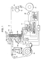
- Fig. 1 is a schematic view, i.e. a combination of a schematic diagram of a shedding device according to a first embodiment of the present invention as viewed from a side, and a control block diagram;
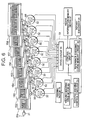
- Fig. 2 is a schematic view, i.e. a combination of a schematic diagram of the shedding device as viewed from the front and the control block diagram;
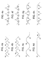
- Figs. 3a to 3f are graphs each showing a shedding curve;
- Figs. 4a to 4d are graphs respectively showing shedding
patterns for
heddle frames - Figs. 5a to 5f are graphs showing shedding curves in a second embodiment;
- Fig. 6 is a schematic view, i.e. a combination of a schematic diagram of a shedding device and a control block diagram according to a third embodiment;
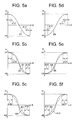
- Figs. 7a and 7b are graphs showing shedding curves;
- Fig. 8 is a table indicating shedding patterns and stationary angles for respective heddle frames; and
- Fig. 9 is a table indicating shedding patterns and stationary angles for respective heddle frames.
-
- A first embodiment of the present invention will be described with reference to Figures 1 to 4.
- Reference symbol Mo designates a weaving machine drive motor, which can rotate reversibly and is operatively controlled by a weaving machine control computer Co. A
reversible feed motor 11, which is provided independently of the weaving machine drive motor Mo, drives awarp beam 12. Warps T1, T2, T3 and T4 are fed out from thewarp beam 12 to be passed through aback roller 13, atension roller 14,heddle frames reed 16. A woven cloth W is passed through anextension bar 17, asurface roller 18, apress roller 19 and a crease removingguide member 20 to be wound onto acloth roller 21. Thesurface roller 18 obtains a driving force from the weaving machine drive motor Mo to receive the woven cloth W in cooperation with thepress roller 19, and thecloth roller 21 is linked with thesurface roller 18. - The
tension roller 14 is attached to one end portion of atension lever 22, so that a predetermined tension to the warp T1, T2, T3 and T4 by the action of atensile spring 23 attached to the other end portion of thetension lever 22. Thetension lever 22 is rotatably supported at one end of adetection lever 24, and the other end of thedetection lever 24 is connected to atension detecting unit 25. The warp tension is transmitted through thetension roller 14, thetension lever 22 and the detection lever 24 to thetension detecting unit 25, and thetension detecting unit 25 outputs, to the weaving machine control computer Co, an electric signal in accordance with the warp tension. The weaving machine control computer Co controls a rotational speed of thefeed motor 11 based on a comparison of a preset tension with a detected tension indicated by this input signal as well as on a warp beam diameter indicated by a detection signal received from arotary encoder 26 for detecting a rotational angle of the weaving machine. With this rotational speed control, the warp tension during a normal operation is controlled to prevent a weaving bar from generating during weaving. - As shown in Fig. 1, shedding drive motor M1, M2, M3 and M4 are disposed below the
heddle frames Crank discs 29 are securely attached to theoutput shafts 28 of the shedding drive motors M1, M2, M3 and M4, and thecrank discs 29 are connected through connectingrods 30 to lower frames of theheddle frames crank discs 29 and the connectingrods 30 constitute crank mechanisms, by which one-directional rotation of the shedding drive motors M1, M2, M3 and M4 are converted into vertical motion of theheddle frames main nozzle 31. - The shedding control device Cl includes a shedding
curve memory circuit 33 that stores therein six shedding curves E1, E2, E3, E4, E5 and E6 shown in Figs. 3a to 3f, acontrol circuit 34 that selects a shedding curve from the sheddingcurve memory circuit 33 and outputs a control command, and adrive circuit 35 that controls the shedding drive motors M1, M2, M3 and M4 based on the control command received from thecontrol circuit 34. Thedrive circuit 35 feed-back controls the shedding drive motors M1, M2, M3 and M4 based on rotational angle information obtained fromrotary encoders 32 built into the shedding drive motors M1, M2, M3 and M4. In Fig. 3, an axis of abscissas represents a weaving machine rotational angle, and an axis H of ordinates represents a height of the heddle frame. The H1 represents the uppermost position, whereas the H2 represents the lowermost position. Each of the shedding curves E1, E2, E3, E4, E5 and E6 represents a part of shedding curves indicative of motion of theheddle frame - The
control circuit 34 is electrically connected to a weaveinformation memory device 27. The weaveinformation memory device 27 stores weave information therein. The weave information stored in the weaveinformation memory device 27 includes shedding patterns of the respective heddle frames 151, 152, 153 and 154. - Fig. 4a represents a
shedding pattern 1/1 of theheddle frame 151, Fig. 4b represents ashedding pattern 1/1 of theheddle frame 152. Fig. 4c represents ashedding pattern 2/2 of theheddle frame 153, and Fig. 4d represents a shedding pattern 6/1 of theheddle frame 154. Fig. 4e is a sectional view of a cloth, showing an interweaving state of the warp T1 and the wefts Y corresponding to theshedding pattern 1/1 shown in Fig. 4a, and Fig. 4f is a sectional view of a cloth, showing an interweaving state of the warp T2 and the wefts Y corresponding to theshedding pattern 1/1 shown in Fig. 4b. Fig. 4g is a sectional view of a cloth, showing an interweaving state of the warp T3 and the wefts Y corresponding to theshedding pattern 2/2 shown in Fig. 4c, and Fig. 4h is a sectional view of a cloth, showing an interweaving state of the warp T4 and the wefts Y corresponding to the shedding pattern 6/1 shown in Fig. 4d. - The weaving machine rotational angle detecting
rotary encoder 26 is electrically connected to thecontrol circuit 34. Thecontrol circuit 34 retrieves the shedding pattern information for each of the heddle frames 151, 152, 153 and 154 from the weaveinformation memory device 27 for every single rotation of the weaving machine on the basis of weaving machine rotational angle information obtained from therotary encoder 26. Concurrently, thecontrol circuit 34 retrieves the transitional pattern for each of the heddle frames 151, 152, 153 and 154 in the next one rotation of the weaving machine. - Since the shedding pattern retrieved by the
control circuit 34 for theheddle frame 151 is theshedding pattern 1/1, thecontrol circuit 34 selects either one of the shedding curves E1 and E4. In the case where the next transitional pattern retrieved by thecontrol circuit 34 from the weaveinformation memory device 27 for theheddle frame 151 is the transitional pattern from the uppermost position to the lowermost position, thecontrol circuit 34 selects the shedding curve E1 from the sheddingcurve memory circuit 33. In the case where the next transitional pattern retrieved by thecontrol circuit 34 from the weaveinformation memory device 27 for theheddle frame 151 is the transitional pattern from the lowermost position to the uppermost position, thecontrol circuit 34 selects the shedding curve E4 from the sheddingcurve memory circuit 33. - Since the shedding pattern retrieved by the
control circuit 34 for theheddle frame 152 is theshedding pattern 1/1, thecontrol circuit 34 selects either one of the shedding curves E1 and E4. In the case where the next transitional pattern retrieved by thecontrol circuit 34 from the weaveinformation memory device 27 for theheddle frame 152 is the transitional pattern from the uppermost position to the lowermost position, thecontrol circuit 34 selects the shedding curve E1 from the sheddingcurve memory circuit 33. In the case where the next transitional pattern retrieved by thecontrol circuit 34 from the weaveinformation memory device 27 for theheddle frame 152 is the transitional pattern from the lowermost position to the uppermost position, thecontrol circuit 34 selects the shedding curve E4 from the sheddingcurve memory circuit 33. - Since the shedding pattern retrieved by the
control circuit 34 for theheddle frame 153 is theshedding pattern 2/2, thecontrol circuit 34 selects either one of the shedding curves E2 and E5. In the case where the next transitional pattern retrieved by thecontrol circuit 34 from the weaveinformation memory device 27 for theheddle frame 153 is the transitional pattern from the uppermost position to the lowermost position, thecontrol circuit 34 selects the shedding curve E2 from the sheddingcurve memory circuit 33. In the case where the next transitional pattern retrieved by thecontrol circuit 34 from the weaveinformation memory device 27 for theheddle frame 153 is the transitional pattern from the lowermost position to the uppermost position, thecontrol circuit 34 selects the shedding curve E5 from the sheddingcurve memory circuit 33. - Since the shedding pattern retrieved by the
control circuit 34 for theheddle frame 154 is the shedding pattern 6/1, thecontrol circuit 34 selects either one of the shedding curves E3 and E6. In the case where the next transitional pattern retrieved by thecontrol circuit 34 from the weaveinformation memory device 27 for theheddle frame 154 is the transitional pattern from the uppermost position to the lowermost position, thecontrol circuit 34 selects the shedding curve E3 from the sheddingcurve memory circuit 33. In the case where the next transitional pattern retrieved by thecontrol circuit 34 from the weaveinformation memory device 27 for theheddle frame 154 is the transitional pattern from the lowermost position to the uppermost position, thecontrol circuit 34 selects the shedding curve E6 from the sheddingcurve memory circuit 33. - The
control circuit 34 outputs control command to thedrive circuit 35 so as to form the shedding curves selected from the sheddingcurve memory circuit 33. Thedrive circuit 35 operates the drive motors M1, M2, M3 and M4 so that the heddle frames 151, 152, 153 and 154 respectively provide the shedding curves thus selected correspondingly. - The disposition period of each
heddle frame heddle frame heddle frame heddle frame heddle frame heddle frame - This definition reflects stationary status of each heddle frames 151, 152, 153 and 154 at the uppermost and lowermost positions during weaving. Hereafter, the disposition period α1, α2, α3 are referred to as stationary angles at the uppermost position side, and the disposition period β1, β2, β3 are referred to as stationary angles at the lowermost position side. In this embodiment, formulae α1 ≈ α2 ≈ a3 « β1 and β1 < β2 < β3 stand in magnitude relationship.
- The first embodiment provides the following effects:
- (1-1) The
control circuit 34, i.e. control means, selects the shedding curves respectively for the heddle frames 151, 152, 153 and 154 from the sheddingcurve memory circuit 33 on the basis of the weave information stored in the weaveinformation memory device 27. Thecontrol circuit 34, which forms shedding curve setting means together with the sheddingcurve memory circuit 33, controls the operation of the shedding drive motors M1, M2, M3 and M4 driving the heddle frames 151, 152, 153 and 154 correspondingly to the selected shedding curves to provide the selected shedding curves. The consumption amounts of the warps T1, T2, T3 and T4 differ from one another depending on the interweaving states to the wefts Y. As can be seen from Figs. 4e to 4h, the consumption amount of warp T3 is smaller than the consumption amount of each of the warps T1 and T2, and the consumption amount of the warp T4 is even smaller than the consumption amount of the warp T3. The respective shedding patterns of a plurality of the heddle frames 151, 152, 153 and 154 reflect the consumption amounts of the warps T1, T2, T3 and T4 corresponding to the heddle frames 151, 152, 153 and 154. The stationary angle α1 in the pair of the shedding curves E1 and E4, the stationary angle α2 in the pair of the shedding curves E2 and E5, and the stationary angle α3 in the pair of the shedding curves E3 and E6 are set to small values, the differential between which is substantially zero. In contrast, the stationary angle β1 in the pair of the shedding curves E1 and E4, the stationary angle β2 in the pair of the shedding curves E2 and E5, and the stationary angle β3 in the pair of the shedding curves E3 and E6 are set values different from one another and the differential therebetween is significant. Each of the stationary angles β2 and β3 is set to a relatively large value. These magnitude differences among the stationary angles β1, β2 and β3 at the lowermost position side provide differences in rapidness of the tension increases on the warps T1, T2, T3 and T4 during the transition from the closed position to the lowermost position, thereby preventing the loosening of the warp (T4 or T3) less consumed. Therefore, the handling of the warps is improved, and the insertion of the wefts is stabilized. That is, the warp handling can be enhanced by selecting the shedding curves respectively for the heddle frames taking into account the stationary angles correspondingly to ratio of one-way movement times, such that the shedding curve having the large stationary angle is prepared for the warp whose consumption amount is small, whereas the shedding curve having the small stationary angle or a zero stationary angle is prepared for the warp whose consumption amount is large. Here, the one-way movement time means the number of movement from the uppermost position to the lowermost position or from the lowermost position to the uppermost position in the shedding pattern. - (1-2) It is experimentally known that a larger stationary angle at the lowermost position side makes the textile quality good. The manner of setting numeric values for stationary angles β1, β2 and β3 at the lowermost side contributes to the improvement of the textile quality.
- (1-3) Since the shedding amount of the warp does not change, there is no case that the tension variation of the warp is increased. Therefore, the textile quality is not degraded by the large tension variation, and it is optimal in view of the improvement of the warp handling to select the shedding curves respectively for the heddle frames taking into account the differences of the stationary angles.
-
- As shown in Figs. 5a to 5f, a second embodiment may be adopted, using the shedding curves E1, E4, E7, E8, E9 and E10 that provide differences among the stationary angles at the uppermost position side, namely α1 = α11 + α12, α2 = α21 + α22 and α3 = α31 + α32. This makes it possible to further enhance the warp handling.
- Next, a third embodiment will be described with reference to Figs. 6 to 8. The same structures as those described in connection with the first embodiment are designated by the same reference symbols.
- In the third embodiment, eight heddle frames 151, 152, 153, 154, 155, 156, 157 and 158 and eight shedding drive motors M1, M2, M3, M4, M5, M6, M7 and M8 are utilized. A reference shedding curve memory circuit 36 of a shedding control device C2 stores therein the reference shedding curve E1 shown in Fig. 3a and the reference shedding curve E4 shown in Fig. 3b. The symbol α1 = α11 + α12 in each of the curves E4 and E1 represents the stationary angle at the uppermost position side, whereas the symbol β1 = β11 + β12 in each of the curves E4 and E1 represents the stationary angle at the lowermost position side. The
control circuit 37 of the shedding control device C2 retrieves, for each of the heddle frames 151 to 158, the shedding pattern information included in the weave information stored in the weaveinformation memory device 27 for every single rotation of the weaving machine on the basis of weaving machine rotational angle information obtained from therotary encoder 26. Thecontrol circuit 37 creates shedding curves from the reference shedding curves E4 and E1 on the basis of the shedding pattern information thus retrieved from the weaveinformation memory device 27, and assigns thus created shedding curves respectively to the heddle frames 151 to 158. The creation of the shedding curves are carried out such that the disposition periods α11, α12, β11 and β12 of the reference shedding curves E4 and E1 are changed. - Fig. 8 shows shedding patterns for the heddle frames 151 to 158. In the illustrated example, the shedding patterns are repeated at sixteen rotation of the weaving machine as a unit cycle. In Fig. 8, the 1/1 pattern corresponds to the shedding patterns shown in Figs. 4a and 4b, and the 2/2 pattern corresponds to the shedding pattern shown in Fig. 4c. The 6/1 pattern corresponds to the shedding pattern shown in Fig. 4d, and the 1/6 pattern corresponds to a shedding pattern obtained by reversing the shedding pattern shown in Fig. 4d upside down. In the illustrated example, each of the heddle frames 151 and 152 makes the motion of the 2/2 pattern for eight times worth of the weft insertion, the motion of the 1/1 pattern for four times worth of the weft insertion, and then the motion of the 2/2 pattern for four times worth of the weft insertion. Each of the heddle frames 153 and 154 makes the motion of the 6/1 pattern for four times worth of the weft insertion, the motion of the 1/6 pattern for four times worth of the weft insertion, the motion of the 1/1 pattern for four times worth of the weft insertion, and then the motion of the 2/2 pattern for four times worth of the weft insertion. Each of the heddle frames 155 and 156 makes the motion of the 1/6 pattern for four times worth of the weft insertion, the motion of the 6/1 pattern for four times worth of the weft insertion, the motion of the 1/1 pattern for four times worth of the weft insertion, and then the motion of the 2/2 pattern for four times worth of the weft insertion. All the motions made by the heddle frames 157, 158 are of the 1/1 pattern.
- In the case where the shedding pattern retrieved by the
control circuit 37 is the 1/1 pattern, thecontrol circuit 37 carries out such a setting that the reference shedding curves E4 and E1 are used as they are. In the case where the shedding pattern retrieved by thecontrol circuit 37 is the 2/2 pattern, thecontrol circuit 37 modifies the disposition periods α11 and β11 of the reference shedding curve E4 to be, for instance, α21 and β21 shown in Fig. 3e, as well as the disposition periods α12 and β12 of the reference shedding curve E1 to be, for instance, α22 and β22 shown in Fig. 3b, to thereby create and set the shedding curves E5 and E2 for use. In the case where the shedding pattern retrieved by thecontrol circuit 37 is the 6/1 pattern, thecontrol circuit 37 modifies the disposition periods α11 and β11 of the reference shedding curve E4 to be, for instance, α31 and β31 shown in Fig. 3f, as well as the disposition periods α12 and β12 of the reference shedding curve E1 to be, for instance, α32 and β32 shown in Fig. 3c, to thereby create and set the shedding curves E6 and E3 for use. In the case where the shedding pattern retrieved by thecontrol circuit 37 is the 1/6 pattern, thecontrol circuit 37 modifies the disposition periods α11 and β11 of the reference shedding curve E4 to be, for instance, α41 and β41 shown in Fig. 7b, as well as the disposition periods α12 and β12 of the reference shedding curve E1 to be, for instance, α42 and β42 shown in Fig. 7a, to thereby create and set the shedding curves E12 and E11 for use. - In Fig. 8, the symbol α (1/1) represents the stationary angle at the uppermost position side corresponding to the 1/1 pattern, and the symbol β (1/1) represents the stationary angle at the lowermost position side corresponding to the 1/1 pattern. The symbol α (2/2) represents the stationary angle at the uppermost position side corresponding to the 2/2 pattern, and the symbol β (2/2) represents the stationary angle at the lowermost position side corresponding to the 2/2 pattern. The symbol α (6/1) represents the stationary angle at the uppermost position side corresponding to the 6/1 pattern, and the symbol β (6/1) represents the stationary angle at the lowermost position side corresponding to the 6/1 pattern. The symbol α (1/6) represents the stationary angle at the uppermost position side corresponding to the 1/6 pattern, and the symbol β (1/6) represents the stationary angle at the lowermost position side corresponding to the 1/6 pattern.
- The
control circuit 37 recognizes next transitional pattern for each of the heddle frames on the basis of the shedding pattern information retrieved from the weaveinformation memory device 27. Assuming for convenience of explanation that the shedding patterns for the heddle frames 151 to 158 are those shown in Fig. 8, in the case where the next transitional pattern for theheddle frame 151 to which the 2/2 pattern is assigned is the transitional pattern from the uppermost position to the lowermost position, thecontrol circuit 37 creates and uses the shedding curve E2. In the case where the next transitional pattern for theheddle frame 151 to which the 2/2 pattern is assigned is the transitional pattern from the lowermost position to the uppermost position, thecontrol circuit 37 creates and uses the reference shedding curve E5. In the case where the next transitional pattern for theheddle frame 151 to which the 1/1 pattern is assigned is the transitional pattern from the uppermost position to the lowermost position, thecontrol circuit 37 uses the reference shedding curve E1 as it is. In the case where the next transitional pattern for theheddle frame 151 to which the 1/1 pattern is assigned is the transitional pattern from the lowermost position to the uppermost position, thecontrol circuit 37 uses the shedding curve E4 as it is. The similar setting of the shedding curve is carried out for theheddle frame 152. - In the case where the next transitional pattern for the
heddle frame 153 to which the 6/1 pattern is assigned is the transitional pattern from the uppermost position to the lowermost position, thecontrol circuit 37 creates and uses the shedding curve E3. In the case where the next transitional pattern for theheddle frame 153 to which the 6/1 pattern is assigned is the transitional pattern from the lowermost position to the uppermost position, thecontrol circuit 37 creates and uses the shedding curve E6. In the case where the next transitional pattern for theheddle frame 153 to which the 1/6 pattern is assigned is the transitional pattern from the uppermost position to the lowermost position, thecontrol circuit 37 creates and uses the shedding curve E11. In the case where the next transitional pattern for theheddle frame 153 to which the 1/6 pattern is assigned is the transitional pattern from the lowermost position to the uppermost position, thecontrol circuit 37 creates and uses the shedding curve E12. In the case where the next transitional pattern for theheddle frame 153 to which the 1/1 pattern is assigned is the transitional pattern from the uppermost position to the lowermost position, thecontrol circuit 37 uses the shedding curve E1 as it is. In the case where the next transitional pattern for theheddle frame 153 to which the 1/1 pattern is assigned is the transitional pattern from the lowermost position to the uppermost position, thecontrol circuit 37 uses the shedding curve E4 as it is. In the case where the next transitional pattern for theheddle frame 153 to which the 2/2 pattern is assigned is the transitional pattern from the uppermost position to the lowermost position, thecontrol circuit 37 creates and uses the shedding curve E2. In the case where the next transitional pattern for theheddle frame 153 to which the 2/2 pattern is assigned is the transitional pattern from the lowermost position to the uppermost position, thecontrol circuit 37 creates and uses the shedding curve E5. The similar setting of the shedding curve is carried out for theheddle frame 154. - In the case where the next transitional pattern for the
heddle frame 155 to which the 1/6 pattern is assigned is the transitional pattern from the uppermost position to the lowermost position, thecontrol circuit 37 creates and uses the shedding curve E11. In the case where the next transitional pattern for theheddle frame 155 to which the 1/6 pattern is assigned is the transitional pattern from the lowermost position to the uppermost position, thecontrol circuit 37 creates and uses the shedding curve E12. In the case where the next transitional pattern for theheddle frame 155 to which the 6/1 pattern is assigned is the transitional pattern from the uppermost position to the lowermost position, thecontrol circuit 37 creates and uses the shedding curve E3. In the case where the next transitional pattern for theheddle frame 155 to which the 6/1 pattern is assigned is the transitional pattern from the lowermost position to the uppermost position, thecontrol circuit 37 creates and uses the shedding curve E6. In the case where the next transitional pattern for theheddle frame 155 to which the 1/1 pattern is assigned is the transitional pattern from the uppermost position to the lowermost position, thecontrol circuit 37 uses the reference shedding curve E1 as it is. In the case where the next transitional pattern for theheddle frame 155 to which the 1/1 pattern is assigned is the transitional pattern from the lowermost position to the uppermost position, thecontrol circuit 37 uses the reference shedding curve E4 as it is. In the case where the next transitional pattern for theheddle frame 155 to which the 2/2 pattern is assigned is the transitional pattern from the uppermost position to the lowermost position, thecontrol circuit 37 creates and uses the shedding curve E2. In the case where the next transitional pattern for theheddle frame 155 to which the 2/2 pattern is assigned is the transitional pattern from the lowermost position to the uppermost position, thecontrol circuit 37 creates and uses the shedding curve E5. The similar setting of the shedding curve is carried out for theheddle frame 156. - In the case where the next transitional pattern for the
heddle frame 157 to which the 1/1 pattern is assigned is the transitional pattern from the uppermost position to the lowermost position, thecontrol circuit 37 uses the reference shedding curve E1 as it is. In the case where the next transitional pattern for theheddle frame 157 to which the 1/1 pattern is assigned is the transitional pattern from the lowermost position to the uppermost position, thecontrol circuit 37 uses the reference shedding curve E4 as it is. The similar setting of the shedding curve is carried out for theheddle frame 158. - The
control circuit 37 outputs control command to thedrive circuit 35 so as to form the shedding curves thus set. Thedrive circuit 35 operates the shedding drive motor M1 to M8 so that the heddle frames 151 to 158 establish the respective shedding curves set correspondingly thereto. - The third embodiment provides the following effects:
- (3-1) The
control circuit 37, i.e. control means, sets the shedding curves respectively for the heddle frames 151 to 158 using the reference shedding curves E4 and E1 stored in the reference shedding curve memory circuit 36 on the basis of the shedding patterns for the heddle frames 151 to 158. Thecontrol circuit 37, which forms shedding curve setting means together with the reference shedding curve memory circuit 36, controls the operation of the shedding drive motors M1 to M8 driving the heddle frames 151 to 158 correspondingly to the thus set shedding curves to provide the thus set shedding curves. -
- The respective shedding patterns of a plurality of the heddle frames 151 to 158 reflect the consumption amounts of the warps corresponding to the heddle frames 151 to 158. The differences among the stationary angles based on the shedding patterns for the heddle frames 151 to 158 provide the differences in rapidness of the tension increases on the warps corresponding to the heddle frames 151 to 158 during the transition from the closed position to the uppermost or lowermost position, thereby preventing the loosening of the warp less consumed. Therefore, the handling of the warps is improved, and the insertion of the wefts is stabilized. That is, the warp handling can be enhanced by setting the shedding curves respectively for the heddle frames taking into account the stationary angles correspondingly to the shedding patterns, such that the shedding curve having the large stationary angle is prepared for the warp whose consumption amount is small, whereas the shedding curve having the small stationary angle is prepared for the warp whose consumption amount is large.
- Next, a fourth embodiment shown in Fig. 9 will be described. The structures of the apparatus in the fourth embodiment are the same as those in the third embodiment, but the
control circuit 37 of the shedding control apparatus C2 in the fourth embodiment differs in function from that in the third embodiment. Thecontrol circuit 37 in the fourth embodiment retrieves, for each of the heddle frames 151 to 158, the shedding pattern information included in the weave information stored in the weaveinformation memory device 27 for every single rotation of the weaving machine on the basis of weaving machine rotational angle information obtained from therotary encoder 26, and also retrieves weft density information included in the weave information. Thecontrol circuit 37 in the fourth embodiment creates shedding curves from the reference shedding curves E4 and E1 on the basis of the thus retrieved shedding pattern information and weft density information, and assigns thus created shedding curves respectively to the heddle frames 151 to 158. The creation of the shedding curves are carried out such that the disposition periods all, α12, β11 and β12 of the reference shedding curves E4 and E1 are changed. Other functions of thecontrol circuit 37 in the fourth embodiment are the same as those in the first embodiment. In the example shown in Fig. 9, the weft density is set to ρ1 for eight times worth of the weft insertion, ρ2 for four times worth of the weft insertion, and then ρ3 for four times worth of the weft insertion. The densities ρ1, ρ2 and ρ3 meet, for instance, a relationship of ρ3 > ρ1 > ρ2. - In Fig. 9, the symbol α(2/2, ρ1) represents the stationary angle at the uppermost position side corresponding to the 2/2 pattern and the weft density ρ1, and the symbol β (2/2, ρ1) represents the stationary angle at the lowermost position side corresponding to the 2/2 pattern and the weft density ρ1. The symbol α (6/1, ρ1) represents the stationary angle at the uppermost position side corresponding to the 6/1 pattern and the weft density ρ1, and the symbol β (6/1, ρ1) represents the stationary angle at the lowermost position side corresponding to the 6/1 pattern and the weft density ρ1. The symbol α (1/6, ρ1) represents the stationary angle at the uppermost position side corresponding to the 1/6 pattern and the weft density ρ1, and the symbol β (1/6, ρ1) represents the stationary angle at the lowermost position side corresponding to the 1/6 pattern and the weft density ρ1. The symbol α (1/1, ρ1) represents the stationary angle at the uppermost position side corresponding to the 1/1 pattern and the weft density ρ1, and the symbol β (1/1, ρ1) represents the stationary angle at the lowermost position side corresponding to the 1/1 pattern and the weft density ρ1. The symbol α (1/1, ρ2) represents the stationary angle at the uppermost position side corresponding to the 1/1 pattern and the weft density ρ2, and the symbol β (1/1, ρ2) represents the stationary angle at the lowermost position side corresponding to the 1/1 pattern and the weft density ρ2. The symbol α (2/2, ρ3) represents the stationary angle at the uppermost position side corresponding to the 2/2 pattern and the weft density ρ3, and the symbol β (2/2, ρ3) represents the stationary angle at the lowermost position side corresponding to the 2/2 pattern and the weft density ρ3. The symbol α (1/1, ρ3) represents the stationary angle at the uppermost position side corresponding to the 1/1 pattern and the weft density ρ3, and the symbol β (1/1, ρ3) represents the stationary angle at the lowermost position side corresponding to the 1/1 pattern and the weft density p3.
- For example, in Fig. 4, the warp T3 is smaller in consumption amount than each of the warps T1 and T2. As the weft densities are larger, the difference in consumption amount between the warp T3 and each of the warps T1 and T2 becomes larger. That is, the weft density influences the consumption amount of the warp. For this reason, the example shown in Fig. 9 carries out such a setting that the stationary angles meet, for instance, a relationship of β (1/1, ρ2) > β (1/1, ρ1) > β (1/1, ρ3). The setting of the shedding curves respectively for the heddle frames taking into account the shedding patterns and the weft densities effectively improves the warp handling.
- In the present invention, the following embodiments can also be employed.
- (1) A plurality of shedding curves, which provide differences only to stationary angles at the uppermost position side, are prepared.
- (2) A plurality of shedding curves, which provide differences to shedding amounts, are prepared, and larger shedding amount is set for warp having smaller consumption amount.
- (3) A plurality of shedding curves having different timings at which heddle frames reach their respective uppermost or lowermost positions, and an earlier timing is set for warp having smaller consumption amount.
- (4) Each of the functions of the weave
information memory device 27, the sheddingcurve memory circuit 33 and thecontrol circuit 37 is installed in the weaving machine control computer Co shown in Fig. 1. - (5) Shedding curves are selected or set respectively for respective heddle frames independently, in accordance with weave information, in order to improve feel and outward appearance of textile.
- (6) Shedding curves are set for respective heddle frames
independently, and stored in the shedding
curve memory circuit 33. The shedding curves are automatically set and stored while referring to the weave information. -
- As has been described in detail, in the present invention, shedding curves are selected or set respectively for a plurality of heddle frames in accordance with weave information, and operation of shedding drive motors driving the heddle frames correspondingly to the respective shedding curves thus selected or set are controlled to provide the thus selected or set shedding curves. Therefore, it is possible to effectively improve the warp handling and the textile quality.
Claims (6)
- A method of controlling sheddings in a weaving machine having a plurality of shedding drive motors provided independently of a weaving machine drive motor, and a plurality of heddle frames, each of the heddle frames corresponding to and driven by a single one of the shedding driving motors,
wherein a shedding curve indicative of motion of one heddle frame for a time period where it is moved from one of the uppermost position and the lowermost position to the other is selected or set for each of said plurality of heddle frames independently on the basis of weave information characterized in that said weave information includes weft density and where the respective shedding curves for the heddle frames are selected or set taking into account stationary angles, and
in that each of said shedding drive motors is drivingly controlled to cause a respective one of said plurality of heddle frames to make a motion along said shedding curve thus set or selected. - The shedding control method in a weaving machine as set forth in claim 1, characterized in that said weave information includes shedding patterns respectively corresponding to said plurality of heddle frames.
- The shedding control method in a weaving machine as set forth in any one of claims 1 and 2, characterized in that at least two kinds of shedding curves distinguished one for the other by the magnitude of stationary angles are beforehand prepared for said shedding curve to be set or selected.
- An apparatus for controlling sheddings in a weaving machine having a plurality of shedding drive motors provided independently of a weaving machine drive motor, and a plurality of heddle frames, each of the heddle frames corresponding to and driven by a respective single one of the shedding driving motors, wherein said shedding control apparatus comprises:shedding curve setting means for storing shedding curves indicative of motion of said heddle frames therein, and selecting or setting, of said shedding curves, a shedding curve indicative of motion of one heddle frame for a time period where it is moved from one of the uppermost position and the lowermost position to the other for each of said plurality of heddle frames independently on the basis of weave information characterized in that said weave information includes weft density inputted therein from the external and where the respective shedding curves for the heddle frames are selected or set taking into account stationary angles, and said shedding control apparatus further comprises:control means for drivingly controlling each of said shedding drive motors to cause the respective one of said plurality of heddle frames to make a motion along said shedding curve thus set or selected by said shedding curve setting means.
- The shedding control apparatus in a weaving machine as set forth in claim 4, characterized in that said weave information includes shedding patterns respectively corresponding to said plurality of heddle frames.
- The shedding control apparatus in a weaving machine as set forth in any one of claims 3 to 5, characterized in that said shedding curve setting means selects or sets at least two kinds of shedding curves distinguished one from the other by the magnitude of stationary angles.
Applications Claiming Priority (2)
| Application Number | Priority Date | Filing Date | Title |
|---|---|---|---|
| JP10771299 | 1999-04-15 | ||
| JP10771299A JP4023028B2 (en) | 1998-11-09 | 1999-04-15 | Method and apparatus for opening control in loom |
Publications (3)
| Publication Number | Publication Date |
|---|---|
| EP1065306A2 EP1065306A2 (en) | 2001-01-03 |
| EP1065306A3 EP1065306A3 (en) | 2001-06-20 |
| EP1065306B1 true EP1065306B1 (en) | 2004-11-10 |
Family
ID=14466042
Family Applications (1)
| Application Number | Title | Priority Date | Filing Date |
|---|---|---|---|
| EP00105970A Expired - Lifetime EP1065306B1 (en) | 1999-04-15 | 2000-03-24 | Shedding control method and apparatus in a weaving machine |
Country Status (1)
| Country | Link |
|---|---|
| EP (1) | EP1065306B1 (en) |
Cited By (1)
| Publication number | Priority date | Publication date | Assignee | Title |
|---|---|---|---|---|
| CN101089269B (en) * | 2006-06-16 | 2011-06-08 | 施托布利法韦日公司 | Device for forming a jacquard type shed, a loom fitted with such a device, and a method of forming the shed on such a loom |
Families Citing this family (7)
| Publication number | Priority date | Publication date | Assignee | Title |
|---|---|---|---|---|
| JP5123525B2 (en) | 2003-04-17 | 2013-01-23 | ピカノール エヌ.ヴィ. | How to drive a loom |
| JP4008384B2 (en) * | 2003-06-13 | 2007-11-14 | 津田駒工業株式会社 | Loom opening control method and apparatus |
| JP4721400B2 (en) * | 2004-10-25 | 2011-07-13 | 津田駒工業株式会社 | Electric opening device of loom |
| JP2007009355A (en) * | 2005-06-29 | 2007-01-18 | Tsudakoma Corp | Electric shedding machine of loom |
| FR2956414B1 (en) * | 2010-02-12 | 2012-03-16 | Staubli Sa Ets | METHOD FOR CONTROLLING ELECTRIC ACTUATORS OF A CROWN FORMATION DEVICE |
| DE102011006368B3 (en) | 2011-03-29 | 2012-02-16 | Lindauer Dornier Gesellschaft Mit Beschränkter Haftung | Method and loom for shedding |
| JP6269587B2 (en) * | 2015-06-15 | 2018-01-31 | 株式会社豊田自動織機 | Pile warp opening control method in a pile loom |
Family Cites Families (4)
| Publication number | Priority date | Publication date | Assignee | Title |
|---|---|---|---|---|
| GB1206122A (en) * | 1967-09-22 | 1970-09-23 | Wilson & Longbottom Ltd | Improvements in dobby motions of looms for weaving |
| JP3242123B2 (en) * | 1991-05-13 | 2001-12-25 | 津田駒工業株式会社 | Loom shedding control device |
| JP3375256B2 (en) * | 1995-10-18 | 2003-02-10 | 津田駒工業株式会社 | Aperture control method and aperture control device |
| JP3840755B2 (en) * | 1997-08-08 | 2006-11-01 | 株式会社豊田自動織機 | Loom opening device |
-
2000
- 2000-03-24 EP EP00105970A patent/EP1065306B1/en not_active Expired - Lifetime
Cited By (1)
| Publication number | Priority date | Publication date | Assignee | Title |
|---|---|---|---|---|
| CN101089269B (en) * | 2006-06-16 | 2011-06-08 | 施托布利法韦日公司 | Device for forming a jacquard type shed, a loom fitted with such a device, and a method of forming the shed on such a loom |
Also Published As
| Publication number | Publication date |
|---|---|
| EP1065306A3 (en) | 2001-06-20 |
| EP1065306A2 (en) | 2001-01-03 |
Similar Documents
| Publication | Publication Date | Title |
|---|---|---|
| EP3638834B1 (en) | Weaving machine, method for simultaneously weaving two pile fabrics on such a machine and pile fabric obtainable with such a method | |
| EP1065306B1 (en) | Shedding control method and apparatus in a weaving machine | |
| US5029616A (en) | Controlling warp tension as a function of weaving pattern | |
| JP4023028B2 (en) | Method and apparatus for opening control in loom | |
| JP3375256B2 (en) | Aperture control method and aperture control device | |
| EP1634983A2 (en) | Pile-formation method and pile-formation device in cloth-shifting-type pile loom | |
| US20080135122A1 (en) | Loom | |
| EP1862573B1 (en) | Operational-error preventing device for loom | |
| CN1327062C (en) | Loom with barre preventing function | |
| CN106400283B (en) | Device for adjusting pile warp tension in towel loom | |
| Gokarneshan et al. | Recent innovations in loom shedding mechanisms | |
| EP1424415B1 (en) | Weaving loom with modulated drive and weaving controlling method featuring variation of the drive speed | |
| JPH10130988A (en) | Control of opening in weaving machine and apparatus therefor | |
| EP0362433B1 (en) | Loom with vertically mobile weft-carrier element for producing double-piece velvets, carpets and the like, including of very long pile | |
| JP3377166B2 (en) | Pile forming equipment | |
| JP3713842B2 (en) | Method and apparatus for opening control in loom | |
| KR100370458B1 (en) | Weaving machine for producing sample fabric using cad/cam system | |
| JPH10331053A (en) | Pile forming apparatus | |
| JP2643429B2 (en) | Control method in loom | |
| JPS63235544A (en) | Fabric changing in weft yarn density, method and loom for weaving the same | |
| CN117328189A (en) | Method for weaving weft density-variable fabric with oblique weft yarns | |
| EP1826302A2 (en) | Shedding device in loom and gaiting method in loom equipped with the shedding device | |
| JP2003003351A (en) | Method for preventing weft bar in weaving machine and device for the same | |
| CN107620146A (en) | A kind of gap weave pattern device of leather fly-shuttle loom | |
| JP2000303297A (en) | Opening controlling apparatus of loom |
Legal Events
| Date | Code | Title | Description |
|---|---|---|---|
| PUAI | Public reference made under article 153(3) epc to a published international application that has entered the european phase |
Free format text: ORIGINAL CODE: 0009012 |
|
| AK | Designated contracting states |
Kind code of ref document: A2 Designated state(s): BE FR |
|
| AX | Request for extension of the european patent |
Free format text: AL;LT;LV;MK;RO;SI |
|
| PUAL | Search report despatched |
Free format text: ORIGINAL CODE: 0009013 |
|
| AK | Designated contracting states |
Kind code of ref document: A3 Designated state(s): AT BE CH CY DE DK ES FI FR GB GR IE IT LI LU MC NL PT SE |
|
| AX | Request for extension of the european patent |
Free format text: AL;LT;LV;MK;RO;SI |
|
| 17P | Request for examination filed |
Effective date: 20011011 |
|
| RAP1 | Party data changed (applicant data changed or rights of an application transferred) |
Owner name: KABUSHIKI KAISHA TOYOTA JIDOSHOKKI |
|
| AKX | Designation fees paid |
Free format text: BE FR |
|
| REG | Reference to a national code |
Ref country code: DE Ref legal event code: 8566 |
|
| 17Q | First examination report despatched |
Effective date: 20030611 |
|
| RTI1 | Title (correction) |
Free format text: SHEDDING CONTROL METHOD AND APPARATUS IN A WEAVING MACHINE |
|
| GRAP | Despatch of communication of intention to grant a patent |
Free format text: ORIGINAL CODE: EPIDOSNIGR1 |
|
| RTI1 | Title (correction) |
Free format text: SHEDDING CONTROL METHOD AND APPARATUS IN A WEAVING MACHINE |
|
| GRAS | Grant fee paid |
Free format text: ORIGINAL CODE: EPIDOSNIGR3 |
|
| GRAA | (expected) grant |
Free format text: ORIGINAL CODE: 0009210 |
|
| AK | Designated contracting states |
Kind code of ref document: B1 Designated state(s): BE FR |
|
| PLBE | No opposition filed within time limit |
Free format text: ORIGINAL CODE: 0009261 |
|
| STAA | Information on the status of an ep patent application or granted ep patent |
Free format text: STATUS: NO OPPOSITION FILED WITHIN TIME LIMIT |
|
| 26N | No opposition filed |
Effective date: 20050811 |
|
| ET | Fr: translation filed | ||
| REG | Reference to a national code |
Ref country code: FR Ref legal event code: PLFP Year of fee payment: 17 |
|
| REG | Reference to a national code |
Ref country code: FR Ref legal event code: PLFP Year of fee payment: 18 |
|
| REG | Reference to a national code |
Ref country code: FR Ref legal event code: PLFP Year of fee payment: 19 |
|
| PGFP | Annual fee paid to national office [announced via postgrant information from national office to epo] |
Ref country code: BE Payment date: 20190215 Year of fee payment: 20 Ref country code: FR Payment date: 20190213 Year of fee payment: 20 |
|
| REG | Reference to a national code |
Ref country code: BE Ref legal event code: MK Effective date: 20200324 |