EP1649986A1 - Method and apparatus for handling a load - Google Patents
Method and apparatus for handling a load Download PDFInfo
- Publication number
- EP1649986A1 EP1649986A1 EP05077299A EP05077299A EP1649986A1 EP 1649986 A1 EP1649986 A1 EP 1649986A1 EP 05077299 A EP05077299 A EP 05077299A EP 05077299 A EP05077299 A EP 05077299A EP 1649986 A1 EP1649986 A1 EP 1649986A1
- Authority
- EP
- European Patent Office
- Prior art keywords
- load
- sensors
- arms
- gripper
- handling
- Prior art date
- Legal status (The legal status is an assumption and is not a legal conclusion. Google has not performed a legal analysis and makes no representation as to the accuracy of the status listed.)
- Granted
Links
- 238000000034 method Methods 0.000 title claims abstract description 15
- 238000012544 monitoring process Methods 0.000 claims abstract description 5
- 238000006073 displacement reaction Methods 0.000 claims description 6
- 238000002604 ultrasonography Methods 0.000 claims description 3
- 230000006835 compression Effects 0.000 description 3
- 238000007906 compression Methods 0.000 description 3
- 239000000969 carrier Substances 0.000 description 2
- 238000005259 measurement Methods 0.000 description 2
- 238000010586 diagram Methods 0.000 description 1
- 230000001105 regulatory effect Effects 0.000 description 1
Images

Classifications
-
- B—PERFORMING OPERATIONS; TRANSPORTING
- B66—HOISTING; LIFTING; HAULING
- B66F—HOISTING, LIFTING, HAULING OR PUSHING, NOT OTHERWISE PROVIDED FOR, e.g. DEVICES WHICH APPLY A LIFTING OR PUSHING FORCE DIRECTLY TO THE SURFACE OF A LOAD
- B66F9/00—Devices for lifting or lowering bulky or heavy goods for loading or unloading purposes
- B66F9/06—Devices for lifting or lowering bulky or heavy goods for loading or unloading purposes movable, with their loads, on wheels or the like, e.g. fork-lift trucks
- B66F9/075—Constructional features or details
- B66F9/12—Platforms; Forks; Other load supporting or gripping members
- B66F9/18—Load gripping or retaining means
- B66F9/183—Coplanar side clamps
-
- B—PERFORMING OPERATIONS; TRANSPORTING
- B25—HAND TOOLS; PORTABLE POWER-DRIVEN TOOLS; MANIPULATORS
- B25J—MANIPULATORS; CHAMBERS PROVIDED WITH MANIPULATION DEVICES
- B25J13/00—Controls for manipulators
- B25J13/08—Controls for manipulators by means of sensing devices, e.g. viewing or touching devices
- B25J13/081—Touching devices, e.g. pressure-sensitive
- B25J13/082—Grasping-force detectors
- B25J13/083—Grasping-force detectors fitted with slippage detectors
-
- B—PERFORMING OPERATIONS; TRANSPORTING
- B66—HOISTING; LIFTING; HAULING
- B66F—HOISTING, LIFTING, HAULING OR PUSHING, NOT OTHERWISE PROVIDED FOR, e.g. DEVICES WHICH APPLY A LIFTING OR PUSHING FORCE DIRECTLY TO THE SURFACE OF A LOAD
- B66F9/00—Devices for lifting or lowering bulky or heavy goods for loading or unloading purposes
- B66F9/06—Devices for lifting or lowering bulky or heavy goods for loading or unloading purposes movable, with their loads, on wheels or the like, e.g. fork-lift trucks
- B66F9/075—Constructional features or details
- B66F9/12—Platforms; Forks; Other load supporting or gripping members
- B66F9/18—Load gripping or retaining means
- B66F9/184—Roll clamps
Landscapes
- Engineering & Computer Science (AREA)
- Structural Engineering (AREA)
- Transportation (AREA)
- Mechanical Engineering (AREA)
- Civil Engineering (AREA)
- Life Sciences & Earth Sciences (AREA)
- Geology (AREA)
- Robotics (AREA)
- Human Computer Interaction (AREA)
- Forklifts And Lifting Vehicles (AREA)
- Crystals, And After-Treatments Of Crystals (AREA)
- Load-Engaging Elements For Cranes (AREA)
- Container, Conveyance, Adherence, Positioning, Of Wafer (AREA)
Abstract
- providing drive signals to one or several drive units arranged to rotate the rotating parts, like rollers, of the sensors,
- monitoring the rotation of the rotating parts by means of the information received from the sensors, and
- determining the proper operation of the sensors and/or the contact between the contact pads and the load by means of the rotation information.
Description
- The present invention relates to a method for handling loads, especially easily damageable goods, like paper rolls or household appliances, with a gripper provided with arms capable of clamping the load by applying a compressive force to the load wherein the compressive force is adjusted on the basis of the slippage measured with slip sensors between the load and the contact pads attached to the arms. The present invention also relates to a gripper provided with arms for handling a load, especially easily damageable goods.
- Paper rolls and other goods, like household appliances, may be handled using a gripper mounted on a forklift truck and having arms which are hydraulically pressed against the load. The compressive force of the arms can be adjusted manually e.g. to four different settings, depending on the load. Especially because of the rough adjustment of the compressive force, the load is often damaged or dropped due to incorrect compression.
- In order to reduce the risk for damaging the load during the handling action the compressive force necessary for lifting and moving the load, like a paper roll or a household appliance, may be optimized. Such a system is disclosed in US Patent 5,929,219. US Patent 5,929,219 discloses a gripper mounted on a forklift truck designed for the lifting and moving of paper rolls. The gripper is provided with turnable arms with plate-like, hinged contact pads. The compressive force is adjusted on the basis of the slippage between the paper roll and the contact pads. The slippage is measured by means of slip sensors mounted on the contact pads. The slip sensors are provided with a rotating roller which is held in contact with the paper roll. As the paper roll slides relative to the contact pads, the roller rotates and the slip sensors measure the relative movement in terms of a pulse count. In US Patent 5,929,219 it is also possible to control and optimize the compressive force during the whole load handling operation, comprising e.g. the lifting operation, the transfer, the rotation and the lowering of the load. The slippage is measured continuously and, if the paper roll starts slipping, the pressure between the contact pads is increased automatically until no slippage occurs.
- It is an object of the present invention to provide an improved system for handling of loads, especially easily damageable goods, whereby the operation of the slip sensors can be controlled. It is further an object of the present invention to provide a system for determining the number of load units and for monitoring the contact between the contact pads attached to the arms and the load.
- This is achieved by providing each slip sensor with a motor that is driving and rotating the sensor roller. With the help of the motor the operation of the slip sensors and the contact between the contact pads and the load can be monitored by detecting the movement of the arms and reading the signals transmitted by the slip sensors. In addition, e.g. in the case of household appliances the number of the load units can also be determined.
- Characteristic features of the present invention are in detail presented in the enclosed claims.
- The advantage of the present invention is that the condition of the slip sensors can be monitored and the failure of the slip sensors thus easily and rapidly identified. Another advantage is that the contact between the contact pads and the load can be verified which eliminates the risk of incorrect positioning of the contact pads in relation to the load. This improves the reliability and efficiency of the load handling. Additionally the number of the load units can be determined automatically.
- The foregoing, and additional objects, features and advantages of the present invention will be more clearly understood from the following detailed description of preferred embodiments of the present invention, taken in conjunction with accompanying drawings, in which:
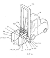
- FIG. 1 presents a forklift truck provided with a gripper according to the present invention,
- FIG. 1A presents another forklift truck provided with a gripper according to the present invention,
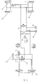
- FIG. 2 presents the hydraulic system,
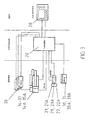
- FIG. 3 presents a block diagram of the control system according to the present invention,
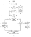
- FIG. 4 presents the flow chart of the slip sensor monitoring operation, and
- FIG. 5 presents a slip sensor arrangement according to the present invention.
- FIG. 1 shows a gripper designed for the lifting and moving of
paper rolls 2 or other loads. The gripper, mounted e.g. on aforklift truck 1 having alifting mast 91, is provided withturnable arms mast 91. One of the arms can be split and the other non-split. The ends of the arms are provided with plate-like, hinged contact pads 8-10 which grip the load. The frame accommodates a hydraulic system comprising a rotation mechanism and hydraulic cylinders 14-17 for turning the arms and ahydraulic valve block 12 with an inbuilt overpressure protection. - FIG. 1A shows another gripper designed for the lifting and moving of especially rectangularly
shaped loads 2A, like household appliances. The gripper, mounted e.g. on aforklift truck 1A having alifting mast 91A, is provided with linearlymovable arms frame 3A by means ofarm carriers contact pads 8A-9A which grip the load. Theframe 3A accommodates a hydraulic system comprising a drive mechanism andhydraulic cylinders 14A-15A for moving the arms linearly and a hydraulic valve block 12A with an inbuilt overpressure protection. Aload rest 93A can be fastened to theframe 3A. - Both grippers are further provided with
slip sensors 21, 21A mounted on thecontact pads roller 22 rotating on an axle and held in contact with the paper roll by a spring and anelectric motor 29, integrated to the sensor and rotating the roller. The grippers are further provided withdisplacement sensors frame 3, 3A orarm carriers - The operating cycle begins when the forklift truck brings the gripper onto the load, so that the
gripper arms arms pressure sensors slip sensors 21, 21A . As the load slips relative to thecontact pads roller - Simultaneously with the slippage measurement, an optional slow lifting action (prelift) may be started. The controller opens the
solenoid valves cylinder 25 of the forklift truck. The optional slow lifting motion enables a precise pressure control. The forklift truck lifts the gripper slowly and the load remains at first unmoved. Thevalves - Based on the slippage, the controller controls a
proportional valve 26 invalve block 12, 12A which adjusts the pressure in the cylinders 14-17, 14A, 15A in accordance with its control signal. The pressure can never rise beyond the value to which the mechanical, spring-loadedpressure limiting valve 27 has been adjusted. The pressure is increased until the gripper holds the load firmly and no slipping occurs. When the load is held firmly the controller stops increasing the pressure and auser interface 28 or equivalent signals the operator that the compression has been completed. The operator may then close themanual valve 13. After this, the operator may perform the desired handling operations, like lifting or turning theload forklift truck - According to the invention, the operation of the slip sensors are monitored in accordance with FIG. 4 as follows: Before or during movement of the
arms load controller 20 starts thesensor control 41 by sending adrive signal 42 to themotor 29. If the slip sensors sendsignals 43 to the controller, the sensors are operating correctly and the clamping is continued at 44, otherwise an error signal is sent at 45 and the handling is interrupted at 46. - At 47, in the case of a gripper provided with turnable arms (FIG 1), if pulses are received by the controller at 48, and the arms are not moving, which can be detected by the
displacement sensors contact 49 and an error message is sent at 50 and the operation is interrupted. If the arms are not moving and the controller is not receiving pulses, then the operation of the load handling is continued at 53 according to the operating cycle described above. - At 47, in the case of a linear movement gripper (FIG. 1A) with at least two slip sensors arranged horizontally one after another all slip sensors are read in order to analyze which slip sensors are transmitting
pulses 51. Based on this analysis the number of load units between the contact pads in lengthwise direction can be determined 52. After that the operation continues at 53. - The number of load units between the arms in transverse direction can naturally be determined when the size of the load units is known by measuring the position of the arms with
displacement sensors - Further, by fastening one or more infrared (IR) or
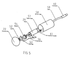
ultrasound detectors 92A to theload rest 93A on a height above the slip sensors (see FIG. 1A) and when the height of each load unit is known, the number of the load units in the vertical direction can be determined by detecting the signals fromdetectors 92A. - FIG. 5 shows an exemplary sensor unit in detail. It comprises a
friction roller 22, a clutch 52 adjacent to the roll,bearings 53, anadapter 54, and amotor 29 on the same shaft as the roller thus capable of rotating the roller. The unit further comprises a fixingspring 56, for fixing the unit into the contact pads, acable tension remover 57, ashrink tube 58 for protecting the unit, aconnection cable 59 and aconnector 60. The unit further comprises anincremental pulse encoder 61 for generating pulse signals according to the rotation. - It is obvious to a person skilled in the art that the invention is not restricted to the example described above, but that it may instead be varied within the scope of the following claims. The slip sensor monitoring can be implemented as provided by the invention regardless of the structure of the arms, e.g. in the case of a gripper provided with two or more split arms and having a linear arm motion. Moreover, the system regulating the compressive force may comprise two or
more controllers 20 e.g. if the system has been designed for simultaneous handling of several paper rolls or household appliances. Further, also other especially easily damageable goods can be handled with a similar manner.
Claims (17)
- A method of handling of loads (2, 2A), especially easily damageable goods, with a gripper provided with arms (6, 7, 6A, 7A) capable of clamping the load by applying a compressive force to the load wherein the compressive force applied to the load is adjusted on the basis of the slippage measured with one or several rotatable slip sensors between the load and contact pads (8, 9, 8A, 9A) arranged in the arms, characterised in that the method comprises following steps:- providing drive signals to one or several drive units (29) arranged to rotate the rotating parts, like rollers, of the sensors,- monitoring the rotation of the rotating parts by means of the information received from the sensors, and- determining the proper operation of the sensors and/or the contact between the contact pads and the load by means of the rotation information.
- The method of handling a load according to claim 1, characterised in that in the method further comprises a step of measuring the position and movement of the arms with displacement sensors (30, 31, 30A, 31A) in order to provide additional information for determining the proper operation of the sensors and/or the contact between the contact pads and the load.
- The method of handling a load according to claim 1 or 2, characterised in that in the method: if the sensor sends signals to the controller, the sensor is operating properly and the handling operation is continued, otherwise an error signal is sent and the handling operation is interrupted.
- The method of handling a load according to claim 1 or 2, characterised in that the movement of the arms is measured, and if pulses are received by the controller, and the arms are not moving, there is no contact and an error message is sent and the handling operation is interrupted.
- The method of handling a load according to claim 1 or 2, characterised in that in that the movement of the arms is measured, and if the arms are not moving and the controller is not receiving pulses, the handling operation is continued.
- The method of handling a load according to claim 1, characterised in that at least two slip sensors are arranged into the arms or contact pads at a horizontal distance from each other, and that pulses from the slip sensors are read in order to determine the number of the load units in the lengthwise direction.
- The method of handling a load according to claim 1, characterised in that displacement sensors (30A, 31A) are arranged in the gripper in order to determine the number of the load units in the transverse direction.
- The method of handling a load according to claim 1, characterised in that at least one infrared (IR), ultrasound or similar sensor is arranged on a height above the slip sensors in order to determine the number of the load units in the vertical direction.
- A gripper for handling of loads (2, 2A), especially easily damageable goods, the gripper being provided with at least one controller (20) and arms (6, 7, 6A, 7A) capable of clamping the load by applying a compressive force to the load wherein the compressive force applied to the load is adjusted on the basis of the slippage measured with one or several rotatable slip sensors between the load and contact pads (8, 9, 8A, 9A) arranged in the arms, characterised in that gripper comprises:- one or several drive units (29) arranged to rotate the rotating parts, like rollers, of the sensors, wherein the controller provides drive signals to the drive units (29),- the controller monitors the rotation of the rotating parts by means of the information received from the sensors, and- the controller determines the proper operation of the sensors and/or the contact between the contact pads and the load by means of the rotation information.
- The gripper according to claim 9, characterised in that in the gripper further comprises means for measuring the movement of the arms in order to provide additional information for determining the proper operation of the sensors and/or the contact between the contact pads and the load.
- The gripper according to claim 9 or 10, characterised in that in the controller: if the sensor sends rotation signals to the controller, the sensor is operating correctly and the load handling operation is continued, otherwise an error signal is sent and the load handling operation is interrupted.
- The gripper according to claim 9 or 10, characterised in that in the controller the movement of the arms is measured, and if pulses are received by the controller, and the arms are not moving, there is no contact with the load and an error message is sent and the load handling operation is interrupted.
- The gripper according to claim 9 or 10, characterised in that in the controller the movement of the arms is measured, and if the arms are not moving and the controller is not receiving pulses, the load handling operation is continued.
- The gripper according to claim 9, characterised in that each sensor is a sensor unit comprising a friction roller (22), a clutch (52), motor (29) in connection with the roller, preferably coaxially with the roller thus capable of rotating the roller, and means for generating pulse signals according to the roller rotation.
- The gripper according to claim 9, characterised in that at least two slip sensors are arranged at a horizontal distance from each other, and that pulses from the slip sensors are read in order to determine the number of the load units in the lengthwise direction.
- The gripper according to claim 9, characterised in that displacement sensors (30A, 31A) are arranged in the gripper in order to determine the number of the load units in the transverse direction.
- The gripper according to claim 9, characterised in that at least one infrared (IR), ultrasound or similar sensor is arranged on a height above the slip sensors in order to determine the number of the load units in the vertical direction.
Applications Claiming Priority (1)
| Application Number | Priority Date | Filing Date | Title |
|---|---|---|---|
| FI20041352A FI117133B (en) | 2004-10-19 | 2004-10-19 | Method and clamping device for handling loads |
Publications (2)
| Publication Number | Publication Date |
|---|---|
| EP1649986A1 true EP1649986A1 (en) | 2006-04-26 |
| EP1649986B1 EP1649986B1 (en) | 2009-03-18 |
Family
ID=33306045
Family Applications (1)
| Application Number | Title | Priority Date | Filing Date |
|---|---|---|---|
| EP05077299A Active EP1649986B1 (en) | 2004-10-19 | 2005-10-10 | Method and apparatus for handling a load |
Country Status (6)
| Country | Link |
|---|---|
| US (1) | US20060104781A1 (en) |
| EP (1) | EP1649986B1 (en) |
| AT (1) | ATE425846T1 (en) |
| CA (1) | CA2523248A1 (en) |
| DE (1) | DE602005013336D1 (en) |
| FI (1) | FI117133B (en) |
Cited By (2)
| Publication number | Priority date | Publication date | Assignee | Title |
|---|---|---|---|---|
| EP1760033A3 (en) * | 2005-09-06 | 2009-11-25 | Auramo OY | Control system for a load handling apparatus |
| EP3305715A1 (en) * | 2016-10-10 | 2018-04-11 | Auramo OY | Forklift, attachment mountable to the forklift, control system for the forklift attachment, and method for lifting a load |
Families Citing this family (10)
| Publication number | Priority date | Publication date | Assignee | Title |
|---|---|---|---|---|
| US7993094B2 (en) * | 2004-06-21 | 2011-08-09 | Tygard Machine & Manufacturing Company | Lift truck |
| US20100300812A1 (en) * | 2009-05-28 | 2010-12-02 | Georgia-Pacifica Consumer Products LP | Forklift Clamp |
| US9630821B2 (en) * | 2011-09-06 | 2017-04-25 | Loron, Inc. | Clamping assembly for load-carrying vehicle |
| CN103693089B (en) * | 2013-12-26 | 2016-01-13 | 上海欣丰电子有限公司 | An a kind of frame carrying point unwheeling |
| US10011468B2 (en) | 2014-10-30 | 2018-07-03 | Cascade Corporation | Pivoting load-bearing assembly with force sensor |
| US10131525B2 (en) * | 2014-10-30 | 2018-11-20 | Cascade Corporation | Pivoting load-bearing assembly with force sensor |
| CN106494470B (en) * | 2016-11-28 | 2019-01-11 | 江苏世丰企业管理咨询有限公司 | A kind of power distribution cabinet carrier with holding function |
| US11136229B2 (en) * | 2016-12-01 | 2021-10-05 | Cascade Corporation | Clamp force control system for lift truck attachment with secondary hydraulic force control circuit |
| JP7424275B2 (en) | 2020-11-12 | 2024-01-30 | 株式会社豊田自動織機 | roll clamp device |
| CN113233388A (en) * | 2021-04-08 | 2021-08-10 | 安徽宇锋智能科技有限公司 | Protective structure for safety of forklift and mounting method of protective structure |
Citations (4)
| Publication number | Priority date | Publication date | Assignee | Title |
|---|---|---|---|---|
| US3904234A (en) * | 1973-10-15 | 1975-09-09 | Stanford Research Inst | Manipulator with electromechanical transducer means |
| EP0443998A1 (en) * | 1990-02-23 | 1991-08-28 | Auramo Oy. | Procedure and apparatus for the handling of loads |
| EP0664272A2 (en) * | 1993-12-10 | 1995-07-26 | Cascade Corporation | Slip-correcting load-clamping system |
| US5929219A (en) | 1997-09-10 | 1999-07-27 | Abbott Laboratories | 9-hydrazone and 9-azine erythromycin derivatives and a process of making the same |
Family Cites Families (7)
| Publication number | Priority date | Publication date | Assignee | Title |
|---|---|---|---|---|
| JPS61241039A (en) * | 1985-04-16 | 1986-10-27 | Nippei Toyama Corp | Confirming device for clamp |
| US4680523A (en) * | 1986-03-13 | 1987-07-14 | Lord Corporation | Apparatus and method for handling articles in automated assembly processes |
| US4714399A (en) * | 1986-05-02 | 1987-12-22 | Cascade Corporation | Automatically-guided vehicle having load clamp |
| US4725826A (en) * | 1987-01-16 | 1988-02-16 | Hunter Bryan D | Manipulator grip slip sensor |
| US5292219A (en) * | 1990-02-23 | 1994-03-08 | Auramo Cargo Systems Oy | Procedure and apparatus for the handling of loads |
| US5280981A (en) * | 1991-02-01 | 1994-01-25 | Odetics, Inc. | End effector with load-sensitive digit actuation mechanisms |
| US6843636B2 (en) * | 1998-10-07 | 2005-01-18 | Cascade Corporation | Adaptive load-clamping system |
-
2004
- 2004-10-19 FI FI20041352A patent/FI117133B/en active IP Right Grant
-
2005
- 2005-10-07 US US11/245,271 patent/US20060104781A1/en not_active Abandoned
- 2005-10-10 AT AT05077299T patent/ATE425846T1/en not_active IP Right Cessation
- 2005-10-10 EP EP05077299A patent/EP1649986B1/en active Active
- 2005-10-10 DE DE602005013336T patent/DE602005013336D1/en active Active
- 2005-10-11 CA CA002523248A patent/CA2523248A1/en not_active Abandoned
Patent Citations (4)
| Publication number | Priority date | Publication date | Assignee | Title |
|---|---|---|---|---|
| US3904234A (en) * | 1973-10-15 | 1975-09-09 | Stanford Research Inst | Manipulator with electromechanical transducer means |
| EP0443998A1 (en) * | 1990-02-23 | 1991-08-28 | Auramo Oy. | Procedure and apparatus for the handling of loads |
| EP0664272A2 (en) * | 1993-12-10 | 1995-07-26 | Cascade Corporation | Slip-correcting load-clamping system |
| US5929219A (en) | 1997-09-10 | 1999-07-27 | Abbott Laboratories | 9-hydrazone and 9-azine erythromycin derivatives and a process of making the same |
Cited By (2)
| Publication number | Priority date | Publication date | Assignee | Title |
|---|---|---|---|---|
| EP1760033A3 (en) * | 2005-09-06 | 2009-11-25 | Auramo OY | Control system for a load handling apparatus |
| EP3305715A1 (en) * | 2016-10-10 | 2018-04-11 | Auramo OY | Forklift, attachment mountable to the forklift, control system for the forklift attachment, and method for lifting a load |
Also Published As
| Publication number | Publication date |
|---|---|
| CA2523248A1 (en) | 2006-04-19 |
| ATE425846T1 (en) | 2009-04-15 |
| US20060104781A1 (en) | 2006-05-18 |
| DE602005013336D1 (en) | 2009-04-30 |
| FI20041352A (en) | 2006-04-20 |
| FI20041352A0 (en) | 2004-10-19 |
| FI117133B (en) | 2006-06-30 |
| EP1649986B1 (en) | 2009-03-18 |
Similar Documents
| Publication | Publication Date | Title |
|---|---|---|
| EP1649986B1 (en) | Method and apparatus for handling a load | |
| US5292219A (en) | Procedure and apparatus for the handling of loads | |
| JP2610117B2 (en) | How to grab your luggage | |
| CN101216374A (en) | Automatic gap adjusting arm detection and adjusting apparatus | |
| WO2021141039A1 (en) | Workpiece conveyance system | |
| FI117864B (en) | Load handling apparatus and method of a control system for a load handling apparatus | |
| EP3677455B1 (en) | Vehicle wheel service apparatus | |
| CN103134668B (en) | Pulley rotation device for detecting flexibility and utilize it to carry out the method detected | |
| EP0443998A1 (en) | Procedure and apparatus for the handling of loads | |
| US20090218835A1 (en) | System for positioning an operating cylinder, use of the system, and machine | |
| CN114193498B (en) | Multipoint adsorption type manipulator clamping jaw and clamping method | |
| CN112846758B (en) | Pull-type clutch disc assembly intelligent production line for heavy truck | |
| JP3852424B2 (en) | Displacement measuring device for material testing machine | |
| CN220490592U (en) | Fatigue strength test board for metal products | |
| JP2004502526A (en) | Device for controlling the tightening of containers in a mixer for fluid products | |
| CN218121386U (en) | Elevator wire rope's pine disconnected detection device based on wireless technology | |
| CN111380643A (en) | Static braking force detection device for safety gear | |
| JPH06199453A (en) | Automatic beam setting method and device thereof | |
| CN214843736U (en) | Torque detection device and system | |
| CN215966121U (en) | Clamping and rotating mechanism of forging manipulator | |
| CN106166565A (en) | Tensioner for rolling equipment | |
| CN206985238U (en) | Paper type detecting system and image processing system | |
| CN115157306A (en) | Industrial robot mechanical clamping jaw performance detection device | |
| KR960009597B1 (en) | Apparatus of adjusting moving products for packaging | |
| JPH0439560Y2 (en) |
Legal Events
| Date | Code | Title | Description |
|---|---|---|---|
| PUAI | Public reference made under article 153(3) epc to a published international application that has entered the european phase |
Free format text: ORIGINAL CODE: 0009012 |
|
| AK | Designated contracting states |
Kind code of ref document: A1 Designated state(s): AT BE BG CH CY CZ DE DK EE ES FI FR GB GR HU IE IS IT LI LT LU LV MC NL PL PT RO SE SI SK TR |
|
| AX | Request for extension of the european patent |
Extension state: AL BA HR MK YU |
|
| 17P | Request for examination filed |
Effective date: 20060602 |
|
| AKX | Designation fees paid |
Designated state(s): AT BE BG CH CY CZ DE DK EE ES FI FR GB GR HU IE IS IT LI LT LU LV MC NL PL PT RO SE SI SK TR |
|
| GRAP | Despatch of communication of intention to grant a patent |
Free format text: ORIGINAL CODE: EPIDOSNIGR1 |
|
| GRAS | Grant fee paid |
Free format text: ORIGINAL CODE: EPIDOSNIGR3 |
|
| GRAA | (expected) grant |
Free format text: ORIGINAL CODE: 0009210 |
|
| AK | Designated contracting states |
Kind code of ref document: B1 Designated state(s): AT BE BG CH CY CZ DE DK EE ES FI FR GB GR HU IE IS IT LI LT LU LV MC NL PL PT RO SE SI SK TR |
|
| REG | Reference to a national code |
Ref country code: GB Ref legal event code: FG4D |
|
| REG | Reference to a national code |
Ref country code: CH Ref legal event code: EP |
|
| REG | Reference to a national code |
Ref country code: IE Ref legal event code: FG4D |
|
| REF | Corresponds to: |
Ref document number: 602005013336 Country of ref document: DE Date of ref document: 20090430 Kind code of ref document: P |
|
| REG | Reference to a national code |
Ref country code: SE Ref legal event code: TRGR |
|
| PG25 | Lapsed in a contracting state [announced via postgrant information from national office to epo] |
Ref country code: SI Free format text: LAPSE BECAUSE OF FAILURE TO SUBMIT A TRANSLATION OF THE DESCRIPTION OR TO PAY THE FEE WITHIN THE PRESCRIBED TIME-LIMIT Effective date: 20090318 Ref country code: LT Free format text: LAPSE BECAUSE OF FAILURE TO SUBMIT A TRANSLATION OF THE DESCRIPTION OR TO PAY THE FEE WITHIN THE PRESCRIBED TIME-LIMIT Effective date: 20090318 Ref country code: FI Free format text: LAPSE BECAUSE OF FAILURE TO SUBMIT A TRANSLATION OF THE DESCRIPTION OR TO PAY THE FEE WITHIN THE PRESCRIBED TIME-LIMIT Effective date: 20090318 |
|
| PG25 | Lapsed in a contracting state [announced via postgrant information from national office to epo] |
Ref country code: AT Free format text: LAPSE BECAUSE OF FAILURE TO SUBMIT A TRANSLATION OF THE DESCRIPTION OR TO PAY THE FEE WITHIN THE PRESCRIBED TIME-LIMIT Effective date: 20090318 Ref country code: LV Free format text: LAPSE BECAUSE OF FAILURE TO SUBMIT A TRANSLATION OF THE DESCRIPTION OR TO PAY THE FEE WITHIN THE PRESCRIBED TIME-LIMIT Effective date: 20090318 Ref country code: PL Free format text: LAPSE BECAUSE OF FAILURE TO SUBMIT A TRANSLATION OF THE DESCRIPTION OR TO PAY THE FEE WITHIN THE PRESCRIBED TIME-LIMIT Effective date: 20090318 |
|
| PG25 | Lapsed in a contracting state [announced via postgrant information from national office to epo] |
Ref country code: BE Free format text: LAPSE BECAUSE OF FAILURE TO SUBMIT A TRANSLATION OF THE DESCRIPTION OR TO PAY THE FEE WITHIN THE PRESCRIBED TIME-LIMIT Effective date: 20090318 |
|
| PG25 | Lapsed in a contracting state [announced via postgrant information from national office to epo] |
Ref country code: CZ Free format text: LAPSE BECAUSE OF FAILURE TO SUBMIT A TRANSLATION OF THE DESCRIPTION OR TO PAY THE FEE WITHIN THE PRESCRIBED TIME-LIMIT Effective date: 20090318 Ref country code: EE Free format text: LAPSE BECAUSE OF FAILURE TO SUBMIT A TRANSLATION OF THE DESCRIPTION OR TO PAY THE FEE WITHIN THE PRESCRIBED TIME-LIMIT Effective date: 20090318 Ref country code: PT Free format text: LAPSE BECAUSE OF FAILURE TO SUBMIT A TRANSLATION OF THE DESCRIPTION OR TO PAY THE FEE WITHIN THE PRESCRIBED TIME-LIMIT Effective date: 20090826 Ref country code: ES Free format text: LAPSE BECAUSE OF FAILURE TO SUBMIT A TRANSLATION OF THE DESCRIPTION OR TO PAY THE FEE WITHIN THE PRESCRIBED TIME-LIMIT Effective date: 20090629 |
|
| PG25 | Lapsed in a contracting state [announced via postgrant information from national office to epo] |
Ref country code: IS Free format text: LAPSE BECAUSE OF FAILURE TO SUBMIT A TRANSLATION OF THE DESCRIPTION OR TO PAY THE FEE WITHIN THE PRESCRIBED TIME-LIMIT Effective date: 20090718 Ref country code: SK Free format text: LAPSE BECAUSE OF FAILURE TO SUBMIT A TRANSLATION OF THE DESCRIPTION OR TO PAY THE FEE WITHIN THE PRESCRIBED TIME-LIMIT Effective date: 20090318 Ref country code: RO Free format text: LAPSE BECAUSE OF FAILURE TO SUBMIT A TRANSLATION OF THE DESCRIPTION OR TO PAY THE FEE WITHIN THE PRESCRIBED TIME-LIMIT Effective date: 20090318 |
|
| PLBE | No opposition filed within time limit |
Free format text: ORIGINAL CODE: 0009261 |
|
| STAA | Information on the status of an ep patent application or granted ep patent |
Free format text: STATUS: NO OPPOSITION FILED WITHIN TIME LIMIT |
|
| PG25 | Lapsed in a contracting state [announced via postgrant information from national office to epo] |
Ref country code: BG Free format text: LAPSE BECAUSE OF FAILURE TO SUBMIT A TRANSLATION OF THE DESCRIPTION OR TO PAY THE FEE WITHIN THE PRESCRIBED TIME-LIMIT Effective date: 20090618 Ref country code: DK Free format text: LAPSE BECAUSE OF FAILURE TO SUBMIT A TRANSLATION OF THE DESCRIPTION OR TO PAY THE FEE WITHIN THE PRESCRIBED TIME-LIMIT Effective date: 20090318 |
|
| 26N | No opposition filed |
Effective date: 20091221 |
|
| PGFP | Annual fee paid to national office [announced via postgrant information from national office to epo] |
Ref country code: NL Payment date: 20091016 Year of fee payment: 5 |
|
| PGFP | Annual fee paid to national office [announced via postgrant information from national office to epo] |
Ref country code: GB Payment date: 20091022 Year of fee payment: 5 |
|
| PG25 | Lapsed in a contracting state [announced via postgrant information from national office to epo] |
Ref country code: MC Free format text: LAPSE BECAUSE OF NON-PAYMENT OF DUE FEES Effective date: 20091031 |
|
| REG | Reference to a national code |
Ref country code: CH Ref legal event code: PL |
|
| REG | Reference to a national code |
Ref country code: FR Ref legal event code: ST Effective date: 20100630 |
|
| PG25 | Lapsed in a contracting state [announced via postgrant information from national office to epo] |
Ref country code: FR Free format text: LAPSE BECAUSE OF NON-PAYMENT OF DUE FEES Effective date: 20091102 |
|
| PG25 | Lapsed in a contracting state [announced via postgrant information from national office to epo] |
Ref country code: IE Free format text: LAPSE BECAUSE OF NON-PAYMENT OF DUE FEES Effective date: 20091010 Ref country code: GR Free format text: LAPSE BECAUSE OF FAILURE TO SUBMIT A TRANSLATION OF THE DESCRIPTION OR TO PAY THE FEE WITHIN THE PRESCRIBED TIME-LIMIT Effective date: 20090619 Ref country code: CH Free format text: LAPSE BECAUSE OF NON-PAYMENT OF DUE FEES Effective date: 20091031 Ref country code: LI Free format text: LAPSE BECAUSE OF NON-PAYMENT OF DUE FEES Effective date: 20091031 |
|
| PG25 | Lapsed in a contracting state [announced via postgrant information from national office to epo] |
Ref country code: LU Free format text: LAPSE BECAUSE OF NON-PAYMENT OF DUE FEES Effective date: 20091010 |
|
| REG | Reference to a national code |
Ref country code: NL Ref legal event code: V1 Effective date: 20110501 |
|
| GBPC | Gb: european patent ceased through non-payment of renewal fee |
Effective date: 20101010 |
|
| PG25 | Lapsed in a contracting state [announced via postgrant information from national office to epo] |
Ref country code: HU Free format text: LAPSE BECAUSE OF FAILURE TO SUBMIT A TRANSLATION OF THE DESCRIPTION OR TO PAY THE FEE WITHIN THE PRESCRIBED TIME-LIMIT Effective date: 20090919 |
|
| PG25 | Lapsed in a contracting state [announced via postgrant information from national office to epo] |
Ref country code: NL Free format text: LAPSE BECAUSE OF NON-PAYMENT OF DUE FEES Effective date: 20110501 Ref country code: GB Free format text: LAPSE BECAUSE OF NON-PAYMENT OF DUE FEES Effective date: 20101010 Ref country code: TR Free format text: LAPSE BECAUSE OF FAILURE TO SUBMIT A TRANSLATION OF THE DESCRIPTION OR TO PAY THE FEE WITHIN THE PRESCRIBED TIME-LIMIT Effective date: 20090318 |
|
| PG25 | Lapsed in a contracting state [announced via postgrant information from national office to epo] |
Ref country code: CY Free format text: LAPSE BECAUSE OF FAILURE TO SUBMIT A TRANSLATION OF THE DESCRIPTION OR TO PAY THE FEE WITHIN THE PRESCRIBED TIME-LIMIT Effective date: 20090318 |
|
| PGFP | Annual fee paid to national office [announced via postgrant information from national office to epo] |
Ref country code: SE Payment date: 20231017 Year of fee payment: 19 Ref country code: IT Payment date: 20231019 Year of fee payment: 19 Ref country code: DE Payment date: 20231020 Year of fee payment: 19 |