EP1649952A1 - Molten metal transportating ladle and method of tapping molten metal - Google Patents
Molten metal transportating ladle and method of tapping molten metal Download PDFInfo
- Publication number
- EP1649952A1 EP1649952A1 EP04748108A EP04748108A EP1649952A1 EP 1649952 A1 EP1649952 A1 EP 1649952A1 EP 04748108 A EP04748108 A EP 04748108A EP 04748108 A EP04748108 A EP 04748108A EP 1649952 A1 EP1649952 A1 EP 1649952A1
- Authority
- EP
- European Patent Office
- Prior art keywords
- gas
- metal
- molten
- ladle
- material layer
- Prior art date
- Legal status (The legal status is an assumption and is not a legal conclusion. Google has not performed a legal analysis and makes no representation as to the accuracy of the status listed.)
- Granted
Links
Images


Classifications
-
- B—PERFORMING OPERATIONS; TRANSPORTING
- B22—CASTING; POWDER METALLURGY
- B22D—CASTING OF METALS; CASTING OF OTHER SUBSTANCES BY THE SAME PROCESSES OR DEVICES
- B22D41/00—Casting melt-holding vessels, e.g. ladles, tundishes, cups or the like
-
- B—PERFORMING OPERATIONS; TRANSPORTING
- B22—CASTING; POWDER METALLURGY
- B22D—CASTING OF METALS; CASTING OF OTHER SUBSTANCES BY THE SAME PROCESSES OR DEVICES
- B22D39/00—Equipment for supplying molten metal in rations
- B22D39/06—Equipment for supplying molten metal in rations having means for controlling the amount of molten metal by controlling the pressure above the molten metal
Landscapes
- Engineering & Computer Science (AREA)
- Mechanical Engineering (AREA)
- Furnace Housings, Linings, Walls, And Ceilings (AREA)
- Casting Support Devices, Ladles, And Melt Control Thereby (AREA)
Abstract
Description
- The present invention relates to a pressure tapping type ladle for transferring molten metal and a molten-metal tapping method for use in transferring and supplying molten metal, such as molten aluminum, to a molten-metal holding furnace placed in a molten-metal casting facility.
- In manufacturing castings of aluminum or aluminum alloy by a die casting method, the casting is usually performed at a plant equipped with many die-casting machines in order to increase productivity. Molten metal is supplied to a die-casting machine by transferring molten metal from a molten-metal holding furnace to a molten-metal ladle, and then supplying molten metal from the molten-metal ladle. Since a predetermined amount of molten metal always needs to be retained in a molten-metal holding furnace, molten metal obtained from a melting furnace located in the plant or molten metal brought from the outside of a plant is continuously supplied thereto so that a predetermined amount of molten metal may be maintained.
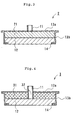
- Fig. 14 is a cross-sectional view of one example of a conventional pressure tapping molten-metal transferring ladle. Fig. 14(a) shows an entire molten-metal transferring ladle and Fig. 14(b) is a view when the working cover is open. The molten-metal transferring ladle shown in Fig. 14 comprises: a
ladle body 101 for holding molten metal; atop cover 102 covering the ladle body; anopenable working cover 103 provided in thetop cover 102; agas inlet 104 that is provided in theworking cover 103 and pressurizes the surface of the molten metal (molten-metal surface) in the ladle; and a molten-metal tapping portion 105 provided in theladle body 101. - The working
cover 103 covers anopening 111 for use in pouring molten metal to theladle body 101, removing scum (aluminum oxide, etc.) formed on the molten-metal surface, measuring the molten-metal temperature, etc. The outer surfaces of theladle body 101, thetop cover 102, and the workingcover 103 are usually covered withsteel shells ladle body 101, thetop cover 102, and the workingcover 103 are laminated with afireproof material 110. Furthermore, in order to raise the heat insulating property, a heat insulating material, etc. , may be laminated between thefireproof material 110 and each of theouter steel shells gas outlet 113 for discharging introduced gas is provided. - For tapping molten metal, a gas, such as air, is introduced through an
opening 112 from thegas inlet 104 to pressurize the molten-metal surface, thereby supplying molten metal to a molten-metal holding furnace from atap hole 106. In the conventional tapping method of inclining a ladle, and then pouring molten metal to a holding furnace while controlling the molten-metal tapping rate, advanced skill is required and the workload is increased for conducting the same procedure at a plurality of molten-metal holding furnaces. By tapping molten metal by pressurizing a molten-metal surface as described above, such disadvantageous operations can be eliminated. - As described above, molten metal may be supplied to a molten-metal holding furnace located inside a casting plant from a metal-melting plant located outside the plant. In this case, a molten-metal transferring ladle containing the molten metal is transported by a truck or like conveyance. When a truck, etc., travels on a public road, the molten-metal surface may shake greatly due to the roughness of the road surface or the curves at street corners. This may accidentally splash molten metal, which will adhere to the inner surface of the
top cover 102 or the workingcover 103. - Fig. 14 shows a molten-metal transferring ladle in which the
gas inlet 104 is formed in the working cover 103 (e.g., Japanese Patent No. 3323489). In the prior-art molten-metal transferring ladle, in which thegas inlet 104 is not formed in the workingcover 103, thegas inlet 104 is provided mainly in thetop cover 102. In the case of the molten-metal transferring ladle shown in Fig. 14, since anopening 112 of thegas inlet 104 is formed in the workingcover 103, which can be provided at a longer distance from the molten-metal surface, the frequency with which the opening is clogged with molten metal or molten-metal splashes is reduced compared with the case where thegas inlet 104 is formed in thetop cover 102. - Forming the
gas inlet 104 in the workingcover 103 reduces the frequency of clogging of the opening of the gas inlet due to molten-metal splashes to some extent. However, it cannot be said that the clogging of the opening is completely prevented considering the fact that clogging may occur due to road surface conditions, the type of conveyance, such as a truck, the amount of molten metal, etc. The clogging of theopening 112 hinders the tapping of molten metal, and in the worst case, the clogging makes it difficult to pour the molten metal. - The invention has been made to solve the above-described problems, and aims to provide a pressure tapping type ladle for transferring molten metal and a molten-metal tapping method, which can reliably introduce a pressurizing gas.
- In order to achieve the above-described objects, a pressure tapping type ladle for transferring molten-metal (1) of the invention comprises: a ladle body for containing molten metal; a top cover covering a top opening of the ladle body; an openable working cover covering an opening formed in a part of the top cover; and a molten-metal tapping portion extending from a lower portion of the ladle body to above the top cover; wherein the working cover is equipped with a cover body covering the opening of the top cover from above, a gas inlet formed in a top panel of the cover body, and a heat-resistant layer provided inside the cover body; the heat-resistant layer is comprised of a gas-permeable fireproof material layer; and gas for pressurizing inside the ladle body is introduced from the gas inlet via the gas-permeable fireproof layer.
- A molten-metal transferring ladle (2) of the invention is characterized in that the heat-resistant layer in the molten-metal transferring ladle (1) is comprised of a gas-permeable heat-insulating material layer between the gas-permeable fireproof material layer and the gas inlet.
- A molten-metal transferring ladle (3) of the invention is characterized in that the heat-resistant layer in the molten-metal transferring ladle (1) is comprised of a heat-insulating material layer having a gas flow portion between the gas-permeable fireproof material layer and the gas inlet.
- A molten-metal transferring ladle (4) of the invention is characterized in that the working cover in any one of the molten-metal transferring ladles (1) to (3) is provided with a space serving as a gas reservoir between the gas inlet and the gas-permeable fireproof material layer, the gas-permeable heat-insulating material layer, or the heat-insulating material layer.
- A molten-metal transferring ladle (5) of the invention is characterized in that the working cover in any one of the molten-metal transferring ladles (1) to (4) is provided on the gas-permeable fireproof material layer surface facing the ladle body with a metal support that supports the gas-permeable fireproof material layer and that has gas permeability.
- A molten-metal transferring ladle (6) of the invention is characterized in that the working cover in the molten-metal transferring ladle (5) is provided with a gas-permeable fireproof material cover covering the metal support on the metal support surface facing the ladle body.
- A molten-metal transferring ladle (7) of the invention is characterized in that the working cover in any one of the molten-metal transferring ladles (1) to (4) is provided on the gas-permeable fireproof material layer surface facing the ladle body with a metal support that supports the gas-permeable fireproof material layer and that has an opening for ventilation and the metal support is provided, at a distance, with a plate for protecting the opening for ventilation under the opening for ventilation.
- A molten-metal transferring ladle (8) of the invention is characterized in that the plate for protecting the opening for ventilation in the molten-metal transferring ladle (7) inclines downward from the center to the outside.
- A molten-metal transferring ladle (9) of the invention is characterized in that the working cover in any one of the molten-metal transferring ladles (1) to (8) is equipped with a gas outlet for discharging gas from the ladle.
- A method for tapping molten metal of the invention comprising: pouring molten metal into the ladle body of any one of the molten-metal transferring ladles (1) to (9), substantially sealing the ladle body with the top cover or the working cover, and introducing a pressurizing gas from the gas inlet via the gas-permeable fireproof material layer to pressurize the surface of the molten metal, thereby tapping molten metal from the molten-metal tapping portion.
- According to the above-described molten-metal transferring ladle (1), the gas-permeable fireproof material layer, which is a heat-resistant layer of the working cover, occupies a large area relative to the ladle body. In other words, the gas-flowing area of the gas-permeable fireproof material layer is large. Therefore, even when the gas-permeable fireproof material layer is partially clogged, gas can flow through non-clogged parts of the layer. Therefore, pressurizing gas is supplied to the molten-metal transferring ladle without any trouble, and thus, molten metal is generally poured with no difficulties. In the case where the gas inlet not only introduces gas into the molten-metal transferring ladle but also discharges gas therefrom, the gas discharge is rarely hindered.
- According to the above-described molten-metal transferring ladle (2) or (3), since the working cover is provided with the heat-insulating material layer, heat dissipation from the working cover can be lessened. This can suppress any drop in the molten metal temperature in the molten-metal transferring ladle.
- According to the above-described molten-metal transferring ladle (4), a space for a gas reservoir is provided between the gas inlet and the gas-permeable fireproof material layer or the gas-permeable heat-insulating material layer. Therefore, even when the provided fireproof material layer or heat-insulating material layer has low gas permeability, the region of the layer corresponding to the part facing the space can serve as a gas-permeable layer. This makes it possible to enlarge the effective gas flow area, as compared with the case where such space is not provided. Moreover, even if the gas-permeable fireproof material layer is partially clogged, the required quantity of gas can be supplied or discharged.
- According to the above-described ladle for transferring molten metal (5), the working cover is provided on the gas-permeable fireproof material layer surface facing the ladle body with a gas-permeable metal support supporting the gas-permeable fireproof material layer. This can prevent the gas-permeable fireproof material layer from falling, and can also support, if used, a gas-permeable fireproof material layer comprised of spherical fire refractory materials.
- Moreover, the above-described ladle for transferring molten metal (6) is provided with a gas-permeable fireproof material cover which covers the above-described metal support. This can prevent the metal support from being weakened or damaged by reaction with adhered molten metal (aluminum, aluminum alloy, etc.).
- Moreover, according to the above-described ladle for transferring molten metal (7), the working cover is provided with a metal support that supports the gas-permeable fireproof material layer and has a ventilation opening on the gas-permeable fireproof material layer surface facing the ladle body, and the metal support is provided with a protection plate for ventilation openings under the opening(s) at a distance from the opening. Therefore, molten metal cannot directly adhere to the gas-permeable fireproof material layer. The ladle for transferring molten metal may shake greatly when transferring or when preparing to pour molten metal. In such a case, molten metal tends to adhere to the gas-permeable fireproof material layer. The adhered molten metal may solidify and separate from the gas-permeable fireproof material layer while partially peeling the layer, which may then drop into the molten metal. Moreover, the adhered molten metal makes it difficult to flow pressurizing gas into the ladle body from the gas-permeable fireproof material layer. According to the ladle for transferring molten metal (7), since the metal support is provided with a protection plate under the ventilation opening, the protection plate can prevent the direct contact of molten metal with the gas-permeable fireproof material layer that is exposed at the ventilation opening. In addition, since molten metal does not easily adhere to the metal support, the work will proceed without any problem and the metal support is not likely to be damaged. Therefore, the ladle of the invention provides stable use over a long period of time.
- According to the above-described ladle for transferring molten metal (8), the protection plate of the ladle for transferring molten metal (7) inclines downward from the center to the outside. Thus, even if molten metal drops such as splashes onto the protection plate, the molten metal drops will easily run down therefrom. Accordingly, molten metal is not likely to solidify and remain on the protection plate. In addition, even if the ladle for transferring molten metal is used with vigorous shaking, it can be used over a long period of time without causing any trouble.
- According to the above-described ladle for transferring molten metal (9), a gas outlet for discharging gas from the ladle for transferring molten metal is provided on the working cover, which facilitates discharging gas. In particular, even if gas needs to be discharged urgently, operating mistakes can be avoided due to the simple operation.
- According to the above-described molten-metal tapping method, molten metal is contained, transferred, and tapped using any one of the above-described ladles for transferring molten metals (1)-(9). Thus, pressurizing gas can be supplied to the ladle body with no difficulties, and molten metal can be poured reliably.
-
- Fig. 1 is a cross-sectional view showing the configuration of a working cover for use in the ladle for transferring molten metal according to Embodiment (1) of the invention.
- Fig. 2 is a cross-sectional view specifically showing the construction of a gas-permeable fireproof material layer.
- Fig. 3 is a cross-sectional view showing the configuration of a working cover for use in the ladle for transferring molten metal according to Embodiment (2) of the invention.
- Fig. 4 is a cross-sectional view showing the configuration of a working cover for use in the ladle for transferring molten metal according to Embodiment (3) of the invention.
- Fig. 5 is a cross-sectional view showing the configuration of a working cover for use in the ladle for transferring molten metal according to Embodiment (4) of the invention.
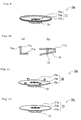
- Fig. 6 is a view showing the configuration of a working cover for use in the ladle for transferring molten metal according to Embodiment (5) of the invention. Fig. 6(a) is a cross-sectional view thereof and Fig. 6(b) is a plan view thereof.
- Fig. 7 is a view showing the configuration of a working cover for use in the ladle for transferring molten metal according to Embodiment (6) of the invention. Fig. 7(a) is a cross-sectional view thereof and Fig. 7(b) is a plan view thereof.
- Fig. 8 is a view showing the configuration of a working cover for use in the ladle for transferring molten metal according to Embodiment (7) of the invention. Fig. 8(a) is a cross-sectional view thereof and Fig. 8(b) is a plan view thereof.
- Fig. 9 is a perspective view showing a metal support constituting the working cover for use in the ladle for transferring molten metal according to Embodiment (7) of the invention.
- Fig. 10 is a partially enlarged cross-sectional view showing a part of the metal support constituting the working cover for use in the ladle for transferring molten metal according to Embodiment (7) of the invention. Fig. 10(a) shows the configuration of an edge part. Fig. 10(b) shows an attached part of a protection plate.
- Fig. 11 is a perspective view showing another embodiment of the metal support constituting the working cover for use in the ladle for transferring molten metal according to Embodiment (7) of the invention.
- Fig. 12 is a perspective view showing still another embodiment of the metal support constituting the working cover for use in the ladle for transferring molten metal according to Embodiment (7) of the invention.
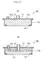
- Fig. 13 is a cross-sectional view showing the configuration of a working cover for use in the ladle for transferring molten metal according to Embodiment (8) of the invention. Fig. 13(a) shows an example in which a gas outlet is provided on a working cover consisted of a gas-permeable fireproof material layer. Fig. 13(b) shows an example in which a gas outlet is provided on a working cover comprised of a gas-permeable fireproof material layer and a heat-insulating material layer.
- Fig. 14 is a cross sectional view showing an example of a conventional pressure tapping type ladle for transferring molten metal.
- The molten-metal transferring ladles according to embodiments of the present invention are described below with reference to the drawings. In each drawing, the same or similar parts are designated by the same reference numerals, and their descriptions may be omitted.
- The targeted molten-metal transferring ladle of the invention is a pressure tapping type ladle for transferring molten metal. The configuration of the principal parts is almost the same as that of the conventional pressure tapping type ladle for transferring molten metal shown in Fig. 14 according to one embodiment. In particular, the difference lies in the configuration of the working cover, and thus the working cover is mainly explained in detail.
- As shown in Fig. 14, the principal parts of the pressure tapping type ladle for transferring molten metal comprise: a
ladle body 101 for containing molten metal; atop cover 102 covering a top opening of the ladle body; and an openable workingcover 103 covering the opening formed in a part of thetop cover 102. The workingcover 103 is equipped with acover body 109 covering the opening of thetop cover 102 from above, agas inlet 104, formed in a top panel of thecover body 109 for introducing gas for pressurizing the molten metal surface in the ladle, a heat-resistant layer provided inside thecover body 109, and a molten-metal tapping portion extending from a lower end portion of theladle body 101 to above theladle body 101. The outer surfaces of theladle body 101 and thetop cover 102 are configured withsteel shells liner 110 comprised of a fireproof material alone or a combination of a fireproof material and a heat-insulating material is provided inside thesteel shells ladle body 101, thetop cover 102, etc. - In most cases, the amount of molten metal contained in the ladle for transferring molten metal is about 1000 kgf. In such a case, the size of the ladle for transferring molten metal is as follows: the height from the bottom of the
ladle body 101 to the workingcover 103 is about 700 mm to about 1200 mm, the outer diameter of, for example, thetop cover 102, is about 1000 mm to about 1400 mm, the inner diameter (the space defined by the liner 110) of theladle body 101 is about 700 mm to about 1000 mm, and the depth is about 700 mm to about 1000 mm. With respect to the workingcover 103, its outer diameter is about 500 mm and its thickness is about 100 mm to about 150 mm. The inside of the steel shell of thecover body 109 is laminated with, for example, a fireproof material having a thickness of about 25 mm to about 100 mm. - A heat-resistant (for example, carbon-based) sealing material, etc.) is used to seal substantially between the
ladle body 101 and thetop cover 102 as well as thetop cover 102 and the workingcover 103. This sealing is sufficient to allow the ladle inside to stand the pressure applied when molten metal is poured, i.e., about 6 × 10⁴ Pa (about 0.6 kgf/cm2) (gauge pressure, maximum). Moreover, a certain amount of gas leakage is acceptable insofar as the control of the pressure inside the ladle is not hindered. The tappingportion 105 is not limited to the type shown in Fig. 14, and any type of tapping portion can be used insofar as it can be applied to the pressure tapping type ladle for transferring molten metal. - Fig. 1 is a cross-sectional view of the configuration of the working cover for use in the ladle for transferring molten metal according to Embodiment (1) of the invention. The working
cover 1 shown in Fig. 1 is equipped with agas inlet 11 and a gas-permeablefireproof material layer 12, which is a heat-resistant layer. The upper side and the side walls of the workingcover 1 are made ofsteel shells like sealing member 14 is joined to the bottom end of thesteel shell 13b of the side walls. - Between the
gas inlet 11 and a gas supply unit (not shown) is provided a pressure controller (not shown) for controlling the pressure in the molten-metal transferring ladle. If required, by providing a valve for switching the mode between gas introduction and gas discharge, the pressure controller may be provided with a function of discharging the gas in the molten-metal transferring ladle through thegas inlet 11. In most cases, air is used as the pressurizing gas, but an inert gas, such as nitrogen gas, argon gas, etc., may also be used. - Fig. 2 is a cross-sectional view showing a specific construction of the gas-permeable
fireproof material layer 12. Fig. 2 (a) shows that the gas-permeablefireproof material layer 12 is wholly comprised of a gas-permeable porousfireproof material layer 12a, such as an alumina, mullite (silica-alumina), silica, or calcium silicate-based porous sintered material having fine pores with a diameter of about 1 mm or less, for example. These porous sintered materials have comparatively low gas permeability. - Fig. 2(b) shows one example of the gas-permeable
fireproof material layer 12 in which gas flows through the gaps of an interlaced framework or string-like materials. For example, the gas-permeablefireproof material layer 12 is wholly comprised of aporous material layer 12b with a three-dimensional framework structure which has a remarkably high porosity and continuous pores (e.g., trade name: "ceramic foam"). The porous material with a three-dimensional framework structure is also used as a filter for filtering impurities, such as oxides, which usually exist in molten aluminum or aluminum alloy, and the gas permeability is noticeably high because the porosity is 80% to 90%. In addition, the porous material with a three-dimensional framework structure has high fire resistivity because it is comprised of, for example, an alumina-cordierite, alumina, or mullite-based fireproof material. Accordingly, the porous material of a three-dimensional framework structure is preferable as the gas-permeablefireproof material layer 12b. - A gas-permeable string-pack sintered material in which string-like fireproof materials are packed and sintered is mentioned as one example in which gas flows through the gaps of string-like materials. This string-like fireproof material is also preferable as the gas-permeable
fireproof material layer 12b. Furthermore, a gas-permeable-fiber formed object obtained by forming fireproof fibers into a board shape is mentioned, and is preferable as the highly gas-permeablefireproof material layer 12b. - Fig. 2(c) shows that the gas-permeable
fireproof material layer 12 is comprised of a porousfireproof material layer 12a and a non-gas-permeablefireproof material layer 15. Fig. 2(d) shows an example of the gas-permeablefireproof material layer 12 that is comprised of aporous material layer 12b with a three-dimensional frame structure and a non-gas-permeable fireproof material layer, such as a castable refractory and afireproof brick 15. As shown in Figs. 2 (c) and (d), the whole area of the gas-permeablefireproof material layer 12 is not necessarily comprised of a gas-permeable fireproof material layer. The gas-permeablefireproof material layer 12 is necessary to have gas permeability as the whole material layer. However, it is preferable to determine a proportion of the area of the non-gas-permeablefireproof material layer 15 that will ensure gas permeability even if the layer is partially clogged by the splash of molten metal, etc. - When the gas-permeable
fireproof material layer 12 is partially non-gas-permeable as shown in Figs. 2 (c) and (d), it is preferable to provide a space that serves as a header for a gas reservoir, which is described later, between the gas-permeablefireproof material layer 12 and thegas inlet 11. - Fig. 2 (e) shows an example of a
fireproof material layer 12c in which the gas-permeablefireproof material layer 12 is comprised of spheres produced from, for example, an alumina, mullite (silica-alumina), or calcium silicate-based fireproof material. Thisfireproof material layer 12c is provided with two gas-permeable holding members 16a for holding a given thickness of the sphere-bearing layer of the fireproof material and gas-permeableside wall members 16b for holding the two holdingmembers 16a at a predetermined interval. - The holding
member 16a has gas permeability and is comprised of a net-like or plate-like metallic material with many holes. A heat-resistant or oxidation-resistant metallic material, such as a Cr-Mo, or stainless steel-based steel material, etc., is suitable for the holdingmember 16a or theside wall member 16b. Moreover, the mesh opening and the hole diameter are determined so that the spheres of fireproof material will not leak out. In order to ensure moderate gas permeability, the sphere size of the fireproof material is preferably within the range of about 5 mm to about 20 mm in diameter. - The spheres of the fireproof material need not be held directly by the holding
member 16a, and may be covered with a sheet-like permeable fireproof material and then held by the holdingmember 16a through the sheet-like fireproof material. In that case, the mesh opening and the hole diameter of the holding member can be made larger than the sphere diameter of the fireproof material. In addition, although the above description is given to the case where the fireproof material is comprised of spheres, the shape is not limited to a spherical shape. Any shape other than spherical, such as a square shape, an amorphous shape, etc., is acceptable insofar as there are gaps between grains. - The thickness of the permeable
fireproof material layer 12 shown in Figs . 2 (a)-(e) is about 25 mm to about 100 mm as described above. - Fig. 3 is a cross-sectional view of the configuration of a working
cover 2 for use in the molten-metal transferring ladle according to Embodiment (2) of the invention. The heat-resistant layer shown in Fig. 3 comprises the same gas-permeablefireproof material layer 12 as in the above-described workingcover 2 described with reference to Fig. 1 and Fig. 2, and the difference therebetween lies only in the thickness of the gas-permeablefireproof material layer 12. Thus, a detailed description is omitted. - The working
cover 2 shown in Fig. 3 is comprised of a gas-permeable heat-insulatinglayer 21 between thegas inlet 11 and the gas-permeablefireproof material layer 12. Any material can be used as the gas-permeable heat-insulatinglayer 21 insofar as the material has heat resistivity up to about 800°C, gas permeability, and insulation properties. For example, a porous material shaped into a plate-like form or a block-like form or a fiber material obtained by forming fiber (short fibers) into a board or a sheet (e.g., trade name: "kaowool", etc.). - The thickness relation between the gas-permeable
fireproof material layer 12 and the gas-permeable heat-insulatinglayer 21 vary depending on the design and according to the insulation efficiency of the entire layer, the thermal conductivity of the gas-permeablefireproof material layer 12 and the gas-permeable heat-insulatinglayer 21, the strength of each material, etc. Thus, the thickness of each layer is preferably determined according to the conditions thereof. However, in order to achieve a certain degree of heat insulating effect, the thickness of the gas-permeable heat-insulatinglayer 21 is preferably at least about 30 mm. - Fig. 4 is a cross-sectional view showing the configuration of a working
cover 3 for use in the molten-metal transferring ladle according to Embodiment (3) of the invention. Since the heat-resistant layer shown in Fig. 4 comprises the same gas-permeablefireproof material layer 12 as in the above-described workingcover 1, and the difference therebetween lies only in the thickness of the gas-permeablefireproof material layer 12, a detailed description is omitted. - The working
cover 3 shown in Fig. 4 is comprised of a heat-insulatinglayer 31 having agas flow portion 32 between thegas inlet 11 and the gas-permeablefireproof material layer 12. Thegas flow portion 32 is an opening formed in the heat-insulatingmaterial layer 31 for use in introducing pressurizing gas into the molten-metal transferring ladle and discharging gas from the molten-metal transferring ladle. Between thegas flow portion 32 and the molten-metal transferring ladle, gas flows through the gas-permeablefireproof material layer 12. - The heat-insulating
layer 31 does not require gas permeability, and any material with heat resistivity up to about 800°C and thermal insulation properties can be used. For example, a heat-insulating castable refractory and porous formed material, etc. , can be used for the heat-insulatinglayer 31. In addition, the above-described gas-permeable fiber formed material (e.g., trade name: "kaowool", etc.) can also be used. - The thickness relations between the gas-permeable
fireproof material layer 12 and the gas-permeable heat-insulatinglayer 31 vary depending on the design and according to the insulation efficiency of the entire layer, the thermal conductivity of the gas-permeablefireproof material layer 12 and gas-permeable heat-insulatinglayer 31, the strength of each material, etc. Thus, the thickness is preferably determined according to the conditions thereof. However, in order to achieve a certain degree of heat insulating effect, the thickness of the gas-permeable heat-insulatinglayer 31 is preferably at least about 30 mm. - Fig. 5 is a cross-sectional view of the configuration of the working cover for use in the molten-metal transferring ladle according to Embodiment (4) of the invention. The working covers 4a (Fig. 5 (a)), 4b (Fig. 5 (b)), and 4c (Fig. 5 (c)) shown in Fig. 5 correspond to the working
cover 1 shown in Fig. 1, the workingcover 2 shown in Fig. 3, and the workingcover 3 shown in Fig. 4, respectively. However, there is a difference in thatspaces fireproof material layer 12 or the gas-permeable heat-insulatinglayer 21 and thegas inlet 11. In the case of the workingcover 4c shown in Fig. 5(c), since the heat-insulatinglayer 31 is non-gas-permeable, thespace 41b is disposed between the gas-permeablefireproof material layer 12 and the heat-insulatinglayer 31. - The area of the
spaces fireproof material layer 12 or the gas-permeable heat-insulatinglayer 21. However, it is preferable to enlarge the space when the gas permeability of the gas-permeablefireproof material layer 12 or the gas-permeable heat-insulatinglayer 21 is low. For example, when a layer with low gas permeability, such as a porous sintered material (Fig. 2(a), for example), is used, it is preferable to determine, according to the gas permeability, the space area relative to the area of the gas-permeablefireproof material layer 12 or the gas-permeable heat-insulatinglayer 21. Each height (thickness) of thespaces - These
spaces fireproof material layer 12 alone or the combination of the gas-permeable heat-insulatinglayer 21 and the gas-permeablefireproof material layer 12 is low. More specifically, by enlarging the area of the gas-permeablefireproof material layer 12 or the gas-permeable heat-insulatinglayer 21 facing thespace - Fig. 6 is a cross sectional view of the configuration of the working cover for use in the molten-metal transferring ladle according to Embodiment (5) of the invention. The working cover 5 shown in Fig. 6 is provided with a
metal support 51 on the undersurface of the gas-permeablefireproof material layer 12. Themetal support 51 has the effect of preventing the fall of the gas-permeablefireproof material layer 12 and supporting the gas-permeablefireproof material layer 12c comprised of spherical fireproof materials shown in Fig. 2(e). Themetal support 51 is preferably attached inside the sealingmember 14 so as not to damage the sealing between thetop cover 102 and each of the working covers 1 to 3 and 4a to 4c. - For the above-described
metal support 51, a wire net, lattice bar steel, metal plate with many holes, and the like are preferable because the gas will then flow between the gas-permeablefireproof material layer 12 and theladle body 101 without any trouble. Suitable as a metallic material for themetal support 51 are a heat-resistant and oxidation-resistant steel material, such as a Cr-Mo or stainless steel-based metallic material. - Fig. 7 is a cross sectional view of the configuration of the working cover for use in the molten-metal transferring ladle according to Embodiment (6) of the invention. The working
cover 6 shown in Fig. 7 is provided with a gas-permeablefireproof material cover 61 on the undersurface (facing the ladle body 101) of themetal support 51 in the working cover 5 according to the above-described embodiment (5). This gas-permeablefireproof material cover 61 prevents damage to themetal support 51 caused by the adhesion of molten aluminum or aluminum alloy. Ordinally, a brittle intermetallic compound tends to generate due to the alloying of aluminum and iron. Therefore, the durability of themetal support 51 can be improved by preventing the direct adhesion of molten metal, such as aluminum, to themetal support 51. - A nonwoven sheet formed of glass fiber or the like is suitable for the gas-permeable
fireproof material cover 61. A heat insulating cloth, etc., is used industrially, and any material can be used as the gas-permeablefireproof material cover 61. It is not absolutely necessary to attach the gas-permeablefireproof material cover 61 to the workingcover 6. The nonwoven sheet may be held between thetop cover 102 and the working cover. Since the gas-permeable fireproof material cover 62 is needed especially when conveying the molten-metal transferring ladle containing molten metal, the cover 62 may be used only during the conveyance. - Fig. 8 shows the configuration of the working cover for use in the molten-metal transferring ladle according to Embodiment (7) of the invention. Fig. 8(a) is a cross sectional view thereof and Fig. 8(b) is a plan view as viewed from the bottom. The working cover 7 shown in Fig. 8 is provided with a
metal support 70a on the undersurface of the gas-permeablefireproof material layer 12 in the workingcover 4c according to the above-described embodiment (4). Themetal support 70a is comprised of abody 71, aprotection plate 72 for ventilation openings (hereafter referred to as "protection plate"), and a fixingmember 73 for fixing theprotection plate 72 to thebody 71. Although Fig. 8 shows an example in which themetal support 70a is attached to the workingcover 4c according to Embodiment (4), themetal support 70a can be attached to any of the working covers according to Embodiments (1) to (4). - Fig. 9 is a perspective view of the
metal support 70a. Fig. 10 is a partially enlarged cross sectional view of a part of themetal support 70a. Fig. 10(a) shows anedge 71c of thebody 71, and Fig. 10(b) shows a fixing part of the fixingmember 73. - As shown in Fig. 9, the
body 71 is provided with abase plate 71a and anedge 71c. On thebase plate 71a, a plurality ofventilation openings 71b are formed. Theprotection plate 72 is located under and separated from theventilation openings 71b. The size of the plate corresponds to the region where theventilation openings 71b are formed. - The
ventilation opening 71b is an opening for flowing gas passing through the gas-permeablefireproof material layer 12 into the ladle and are formed near the central part of thebase plate 71a. It is preferable to form two ormore ventilation openings 71b, but a plurality of openings are not absolutely necessary and one opening may be sufficient. The size of eachventilation opening 71b is favorably determined according to the space capacity of the upper part of the molten metal body, the flow rate of pressurizing gas, the number of ventilation opening(s) 71b, etc. - It is preferable that the
protection plate 72 inclines downward from the central part to the outside, and is almost in the shape of an ancient soldier's straw hat. The plate does not necessarily incline downwardly in a linear manner, and may incline downwardly in a curved manner or the like. The plate inclining downwardly from the central part to the outside as described above facilitates dropping and flowing molten metal splashed on theprotection plate 72 from the plate. The upper limit of the size (diameter) of theprotection plate 72 is favorably determined so as to provide at least about a 20 mm gap between the opening 111 of the ladle (Fig. 14) and theprotection plate 72 when the working cover 7 is placed on the ladle. - The
body 71 and theprotection plate 72 may be connected to each other by the fixingmember 73. Fig. 10(b) shows an example of a fixing manner using the fixingmember 73. Fig. 10(b) shows a favorable fixing method in which openings are formed in thebase plate 71a and theprotection plate 72, and then a bar-like fixingmember 73 is inserted in each openings, and connected by welding, etc. - As shown in Fig. 10(a), a
projection 71e is desirably formed in anedge 71c of thebody 71. Thisprojection 71e is used for precise positioning while attaching thebody 71 to the working cover 7. The working cover 7 shown in Fig. 8 is assembled by, for example, inserting thesupport member 70a into the ring-like sealing member 14 prior to attaching thesteel shell 13a and embedding the heat-insulatingmaterial layer 31, the gas-permeablefireproof material layer 12, etc. In this case, thesupport member 70a is pushed into the sealingmember 14 from above the sealingmember 14 in such a manner that the outer surface of theedge 71c of thesupport member 70a touches the inner surface of the sealingmember 14. When theprojection 71e is pressed until it reaches the upper surface of the sealingmember 14, thesupport member 70a and thebase plate 71a can be correctly positioned relative to the under surface of the sealingmember 14. - Fig. 11 is a perspective view showing a support member according to another embodiment. Fig. 11 shows an example of a
support member 70b that has adifferent edge 71c from thesupport member 70a shown in Fig. 9. Thesupport member 70b is provided with two ormore edges 76c having a narrow circumferential width. Thus, the edge is not necessarily in a ring shape as shown in Fig. 9. - Fig. 12 is a perspective view of a support member according to still another embodiment. Fig. 12 shows an example of a
different support member 70c from thesupport member 70a shown in Fig. 9 and thesupport member 70b shown in Fig. 11 in that theedge edge support member 70c without the edge, theouter periphery 77c of thebase plate 71a may be connected to the sealingmember 14 by welding, or the like. - The
base plate 71a and theprotection plate 72 of eachsupport member base plate 71a is preferably about 4 mm or more and the thickness of theprotection plate 72 is preferably about 3 mm or more, for example. - The shape of the
protection plate 72 provided in eachsupport member - Fig. 13 is a cross-sectional view of the configuration of the working cover for use in the molten-metal transferring ladle according to Embodiment (7) of the invention. Fig. 13 (a) is an example in which a
gas outlet 81a is formed on a workingcover 8a consisting of the gas-permeablefireproof material layer 12. Fig. 13(b) is an example in which a gas outlet 81b is formed on a workingcover 8b comprised of the gas-permeablefireproof material layer 12 and the heat-insulatingmaterial layer 31. - In the
gas outlet 81a shown in Fig. 13 (a), since the workingcover 8a consists of the gas-permeablefireproof material layer 12, thegas outlet 81a opens on the upper surface of the gas-permeablefireproof material layer 12. In the gas outlet 81b shown in Fig. 13 (b), since the workingcover 8b is comprised of the gas-permeablefireproof material layer 12 and the heat-insulatingmaterial layer 31, the gas outlet 81b opens both on the upper surface of the gas-permeablefireproof material layer 12 and on the under surface of the heat-insulatingmaterial layer 31. - As described above, gas in the molten-metal transferring ladle can be discharged from the
gas inlet 11. However, in order to provide separate channels for introducing and discharging gas, it is preferable to form thegas outlets 81a and 81b in the positions shown in Figs. 13(a) and (b). - The pressure tapping type ladle for transferring molten metal of the invention prevents clogging of the opening for introducing gas to pressurize the inside of the ladle while transferring molten metal by, for example, a truck or like conveyance means. Therefore, pressurizing gas can be introduced reliably, and thus, molten metal is poured without any trouble, which leads to a stable tapping process for molten metal.
Claims (10)
- A pressure tapping type ladle for transferring molten-metal comprising:a ladle body for containing molten metal;a top cover covering a top opening of the ladle body;an openable working cover covering an opening formed in a part of the top cover;and a molten-metal tapping portion extending from a lower end portion of the ladle body to above the ladle body; whereinthe working cover is equipped with a cover body covering the opening of the top cover from above, a gas inlet formed in a top panel of the cover body, and a heat-resistant layer provided inside the cover body;the heat-resistant layer is comprised of a gas-permeable fireproof material layer; andgas for pressurizing inside the ladle body is introduced from the gas inlet via the gas-permeable fireproof layer.
- The molten-metal transferring ladle according to Claim 1, wherein the heat-resistant layer is comprised of a gas-permeable heat-insulating material layer between the gas-permeable fireproof material layer and the gas inlet.
- The molten-metal transferring ladle according Claim 1, wherein the heat-resistant layer is comprised of a heat-insulating material layer having a gas flow portion between the gas-permeable fireproof material layer and the gas inlet.
- The molten-metal transferring ladle according to any one of Claims 1 to 3, wherein the working cover is provided with a space serving as a gas reservoir between the gas inlet and the gas-permeable fireproof material layer, the gas-permeable heat-insulating material layer, or the heat-insulating material layer.
- The molten-metal transferring ladle according to any one of Claims 1 to 4, wherein the working cover is provided on the gas-permeable fireproof material layer surface facing the ladle body with a metal support that supports the gas-permeable fireproof material layer and that has gas permeability.
- The molten-metal transferring ladle according to Claim 5, wherein the working cover is provided with a gas-permeable fireproof material cover covering the metal support on the metal support surface facing the ladle body.
- The molten-metal transferring ladle according to any one of Claims 1 to 4, wherein the working cover is provided on the gas-permeable fireproof material layer surface facing the ladle body with a metal support that supports the gas-permeable fireproof material layer and that has an opening for ventilation, the metal support being provided, at a distance, with a plate for protecting the opening for ventilation under the opening for ventilation.
- The molten-metal transferring ladle according to Claim 7, wherein the plate for protecting the opening for ventilation inclines downward from the center to the outside.
- The molten-metal transferring ladle according to any one of Claims 1 to 8, wherein the working cover is equipped with a gas outlet for discharging gas from the ladle.
- A method for tapping molten metal, comprising:pouring molten metal into the ladle body of any one of the molten-metal transferring ladles 1 to 9,substantially sealing the ladle body with the top cover or the working cover, andintroducing a pressurizing gas from the gas inlet via the gas-permeable fireproof material layer to pressurize the surface of the molten metal, thereby tapping molten metal from the molten-metal tapping portion.
Priority Applications (1)
| Application Number | Priority Date | Filing Date | Title |
|---|---|---|---|
| PL04748108T PL1649952T3 (en) | 2003-07-25 | 2004-07-23 | Molten metal transportating ladle and method of tapping molten metal |
Applications Claiming Priority (3)
| Application Number | Priority Date | Filing Date | Title |
|---|---|---|---|
| JP2003279746 | 2003-07-25 | ||
| JP2003351645A JP3613686B1 (en) | 2003-07-25 | 2003-10-10 | A ladle for molten metal transportation and a method for discharging molten metal |
| PCT/JP2004/010901 WO2005009650A1 (en) | 2003-07-25 | 2004-07-23 | Molten metal transportating ladle and method of tapping molten metal |
Publications (3)
| Publication Number | Publication Date |
|---|---|
| EP1649952A1 true EP1649952A1 (en) | 2006-04-26 |
| EP1649952A4 EP1649952A4 (en) | 2010-07-14 |
| EP1649952B1 EP1649952B1 (en) | 2011-07-13 |
Family
ID=34106900
Family Applications (1)
| Application Number | Title | Priority Date | Filing Date |
|---|---|---|---|
| EP04748108A Expired - Fee Related EP1649952B1 (en) | 2003-07-25 | 2004-07-23 | Molten metal transportating ladle and method of tapping molten metal |
Country Status (5)
| Country | Link |
|---|---|
| US (1) | US7354547B2 (en) |
| EP (1) | EP1649952B1 (en) |
| JP (1) | JP3613686B1 (en) |
| PL (1) | PL1649952T3 (en) |
| WO (1) | WO2005009650A1 (en) |
Families Citing this family (6)
| Publication number | Priority date | Publication date | Assignee | Title |
|---|---|---|---|---|
| US8158071B2 (en) * | 2006-04-29 | 2012-04-17 | Chun-Chieh Chang | Method and devices for producing air sensitive electrode materials for lithium ion battery applications |
| KR101188069B1 (en) * | 2007-11-14 | 2012-10-04 | 천-유 창 | Method and devices for producing air sensitive electrode materials for lithium ion battery applications |
| JP5553482B2 (en) * | 2008-03-19 | 2014-07-16 | 日本坩堝株式会社 | Molten metal container |
| JP2012193097A (en) * | 2011-03-18 | 2012-10-11 | Panasonic Corp | Hydrogen generator |
| JP6159861B1 (en) * | 2016-10-07 | 2017-07-05 | 橋本産商株式会社 | Holding furnace |
| CN109822083A (en) * | 2019-03-29 | 2019-05-31 | 江苏德龙镍业有限公司 | A kind of online ladle heat insulation device |
Citations (3)
| Publication number | Priority date | Publication date | Assignee | Title |
|---|---|---|---|---|
| GB2068515A (en) * | 1980-01-31 | 1981-08-12 | Foseco Trading Ag | Porous Plugs in Metallurgical Vessels |
| EP0252318A1 (en) * | 1986-06-09 | 1988-01-13 | Kawasaki Steel Corporation | Pressure type automatic pouring furnace for casting |
| EP1304184A1 (en) * | 2000-06-22 | 2003-04-23 | Hoei Shokai Co., Ltd. | Molten metal feeding method, molten metal feeding system, molten aluminum producing method, aluminum die-cast product producing method, car manufacturing method, transportation vehicle, container, and molten metal feeding device |
Family Cites Families (11)
| Publication number | Priority date | Publication date | Assignee | Title |
|---|---|---|---|---|
| US3810564A (en) * | 1973-06-18 | 1974-05-14 | Midland Ross Corp | Air pressure discharge furnace having protective atmosphere inlet and outlet |
| US4169584A (en) * | 1977-07-18 | 1979-10-02 | The Carborundum Company | Gas injection apparatus |
| CS241483B2 (en) * | 1980-06-25 | 1986-03-13 | Arbed | Refractory building body |
| US5271539A (en) * | 1986-06-09 | 1993-12-21 | Kawasaki Steel Corporation | Pressure type automatic pouring furnace for casting |
| JPH0252164A (en) * | 1988-08-15 | 1990-02-21 | Nippon Rutsubo Kk | Method for carrying molten metal by vehicle and truck and foundry ladle |
| JPH04187359A (en) * | 1990-11-21 | 1992-07-06 | Hitachi Ltd | Low pressure casting device |
| JP3325256B2 (en) * | 2000-04-07 | 2002-09-17 | 株式会社大紀アルミニウム工業所 | Ladle transport device and ladle transport vehicle equipped with it |
| JP2002052164A (en) | 2000-08-08 | 2002-02-19 | Heiwa Corp | Game machine |
| JP3323489B1 (en) | 2000-12-27 | 2002-09-09 | 株式会社豊栄商会 | Container for supplying molten metal |
| US7204954B2 (en) * | 2000-12-27 | 2007-04-17 | Hoei Shokai Co., Ltd. | Container |
| JP3492677B1 (en) | 2002-02-14 | 2004-02-03 | 株式会社豊栄商会 | Molten metal supply container and safety device |
-
2003
- 2003-10-10 JP JP2003351645A patent/JP3613686B1/en not_active Expired - Fee Related
-
2004
- 2004-07-23 WO PCT/JP2004/010901 patent/WO2005009650A1/en active Application Filing
- 2004-07-23 EP EP04748108A patent/EP1649952B1/en not_active Expired - Fee Related
- 2004-07-23 PL PL04748108T patent/PL1649952T3/en unknown
-
2006
- 2006-01-13 US US11/331,543 patent/US7354547B2/en not_active Expired - Fee Related
Patent Citations (3)
| Publication number | Priority date | Publication date | Assignee | Title |
|---|---|---|---|---|
| GB2068515A (en) * | 1980-01-31 | 1981-08-12 | Foseco Trading Ag | Porous Plugs in Metallurgical Vessels |
| EP0252318A1 (en) * | 1986-06-09 | 1988-01-13 | Kawasaki Steel Corporation | Pressure type automatic pouring furnace for casting |
| EP1304184A1 (en) * | 2000-06-22 | 2003-04-23 | Hoei Shokai Co., Ltd. | Molten metal feeding method, molten metal feeding system, molten aluminum producing method, aluminum die-cast product producing method, car manufacturing method, transportation vehicle, container, and molten metal feeding device |
Non-Patent Citations (1)
| Title |
|---|
| See also references of WO2005009650A1 * |
Also Published As
| Publication number | Publication date |
|---|---|
| EP1649952B1 (en) | 2011-07-13 |
| EP1649952A4 (en) | 2010-07-14 |
| WO2005009650A1 (en) | 2005-02-03 |
| JP3613686B1 (en) | 2005-01-26 |
| US7354547B2 (en) | 2008-04-08 |
| PL1649952T3 (en) | 2011-12-30 |
| US20060119024A1 (en) | 2006-06-08 |
| JP2005059093A (en) | 2005-03-10 |
Similar Documents
| Publication | Publication Date | Title |
|---|---|---|
| US7354547B2 (en) | Molten-metal transferring ladle and molten-metal tapping method | |
| EP2927629B1 (en) | Method for producing a molten metal-containing vessel | |
| JP4628303B2 (en) | Molten metal ladle | |
| JP2008529796A (en) | Steel strip continuous casting method and apparatus | |
| NO783965L (en) | METHOD AND DEVICE FOR FILTERING METAL | |
| US20020011696A1 (en) | Tundish impact pad | |
| EP1372888B1 (en) | Refractory plug or brick for injecting gas into molten metal | |
| CN100368123C (en) | Molten-metal transferring ladle and molten-metal tapping method | |
| EP0646430B1 (en) | Refractory block for continuous casting | |
| JP3903321B2 (en) | Molten metal ladle | |
| EP1750075A1 (en) | Crucible for the treatment of molten metal and process for the manufacture thereof | |
| JP7001033B2 (en) | Refining pot lid and refining method of molten iron | |
| US6083453A (en) | Tundish having fume collection provisions | |
| JPH05329623A (en) | Method for preventing nozzle clogging in molten metal vessel | |
| JP3595879B1 (en) | Molten transport container | |
| AU2002244555B2 (en) | Refractory plug or brick for injecting gas into molten metal | |
| JP2004255433A (en) | Slide gate plate | |
| JP2005076071A (en) | Degassing apparatus | |
| JP2002500956A (en) | Container for molten metal for metallurgy | |
| JPS6243655Y2 (en) | ||
| JP2010179340A (en) | Method for removing non-metallic inclusion in steel | |
| JPH1177283A (en) | Funnel for distributing molten metal | |
| JPH0656690U (en) | Electric furnace for steelmaking | |
| JPH0677951U (en) | Vacuum induction melting casting equipment | |
| JPS6199561A (en) | Mounting method of refractory plug for closing outflow hole |
Legal Events
| Date | Code | Title | Description |
|---|---|---|---|
| PUAI | Public reference made under article 153(3) epc to a published international application that has entered the european phase |
Free format text: ORIGINAL CODE: 0009012 |
|
| 17P | Request for examination filed |
Effective date: 20060105 |
|
| AK | Designated contracting states |
Kind code of ref document: A1 Designated state(s): DE PL |
|
| DAX | Request for extension of the european patent (deleted) | ||
| RBV | Designated contracting states (corrected) |
Designated state(s): DE PL |
|
| A4 | Supplementary search report drawn up and despatched |
Effective date: 20100611 |
|
| GRAP | Despatch of communication of intention to grant a patent |
Free format text: ORIGINAL CODE: EPIDOSNIGR1 |
|
| GRAJ | Information related to disapproval of communication of intention to grant by the applicant or resumption of examination proceedings by the epo deleted |
Free format text: ORIGINAL CODE: EPIDOSDIGR1 |
|
| RIC1 | Information provided on ipc code assigned before grant |
Ipc: B22D 41/00 20060101ALI20101014BHEP Ipc: B22D 41/12 20060101ALI20101014BHEP Ipc: B22D 35/00 20060101ALI20101014BHEP Ipc: B22D 39/06 20060101AFI20101014BHEP |
|
| GRAP | Despatch of communication of intention to grant a patent |
Free format text: ORIGINAL CODE: EPIDOSNIGR1 |
|
| GRAS | Grant fee paid |
Free format text: ORIGINAL CODE: EPIDOSNIGR3 |
|
| GRAA | (expected) grant |
Free format text: ORIGINAL CODE: 0009210 |
|
| AK | Designated contracting states |
Kind code of ref document: B1 Designated state(s): DE PL |
|
| REG | Reference to a national code |
Ref country code: DE Ref legal event code: R096 Ref document number: 602004033463 Country of ref document: DE Effective date: 20110901 |
|
| PGFP | Annual fee paid to national office [announced via postgrant information from national office to epo] |
Ref country code: DE Payment date: 20110728 Year of fee payment: 8 |
|
| REG | Reference to a national code |
Ref country code: PL Ref legal event code: T3 |
|
| PLBE | No opposition filed within time limit |
Free format text: ORIGINAL CODE: 0009261 |
|
| STAA | Information on the status of an ep patent application or granted ep patent |
Free format text: STATUS: NO OPPOSITION FILED WITHIN TIME LIMIT |
|
| 26N | No opposition filed |
Effective date: 20120416 |
|
| REG | Reference to a national code |
Ref country code: DE Ref legal event code: R097 Ref document number: 602004033463 Country of ref document: DE Effective date: 20120416 |
|
| PG25 | Lapsed in a contracting state [announced via postgrant information from national office to epo] |
Ref country code: DE Free format text: LAPSE BECAUSE OF NON-PAYMENT OF DUE FEES Effective date: 20130201 |
|
| REG | Reference to a national code |
Ref country code: DE Ref legal event code: R119 Ref document number: 602004033463 Country of ref document: DE Effective date: 20130201 |
|
| REG | Reference to a national code |
Ref country code: PL Ref legal event code: LAPE |
|
| PG25 | Lapsed in a contracting state [announced via postgrant information from national office to epo] |
Ref country code: PL Free format text: LAPSE BECAUSE OF NON-PAYMENT OF DUE FEES Effective date: 20120723 |