EP1649129B1 - Outil de coupe comportant un dispositif servant a transporter des particules d'un materiau magnetique - Google Patents
Outil de coupe comportant un dispositif servant a transporter des particules d'un materiau magnetique Download PDFInfo
- Publication number
- EP1649129B1 EP1649129B1 EP04741976A EP04741976A EP1649129B1 EP 1649129 B1 EP1649129 B1 EP 1649129B1 EP 04741976 A EP04741976 A EP 04741976A EP 04741976 A EP04741976 A EP 04741976A EP 1649129 B1 EP1649129 B1 EP 1649129B1
- Authority
- EP
- European Patent Office
- Prior art keywords
- support surface
- magnetic
- tool
- field
- magnet
- Prior art date
- Legal status (The legal status is an assumption and is not a legal conclusion. Google has not performed a legal analysis and makes no representation as to the accuracy of the status listed.)
- Not-in-force
Links
Images


Classifications
-
- E—FIXED CONSTRUCTIONS
- E21—EARTH DRILLING; MINING
- E21B—EARTH DRILLING, e.g. DEEP DRILLING; OBTAINING OIL, GAS, WATER, SOLUBLE OR MELTABLE MATERIALS OR A SLURRY OF MINERALS FROM WELLS
- E21B21/00—Methods or apparatus for flushing boreholes, e.g. by use of exhaust air from motor
- E21B21/002—Down-hole drilling fluid separation systems
-
- B—PERFORMING OPERATIONS; TRANSPORTING
- B03—SEPARATION OF SOLID MATERIALS USING LIQUIDS OR USING PNEUMATIC TABLES OR JIGS; MAGNETIC OR ELECTROSTATIC SEPARATION OF SOLID MATERIALS FROM SOLID MATERIALS OR FLUIDS; SEPARATION BY HIGH-VOLTAGE ELECTRIC FIELDS
- B03C—MAGNETIC OR ELECTROSTATIC SEPARATION OF SOLID MATERIALS FROM SOLID MATERIALS OR FLUIDS; SEPARATION BY HIGH-VOLTAGE ELECTRIC FIELDS
- B03C1/00—Magnetic separation
- B03C1/02—Magnetic separation acting directly on the substance being separated
- B03C1/025—High gradient magnetic separators
- B03C1/031—Component parts; Auxiliary operations
- B03C1/033—Component parts; Auxiliary operations characterised by the magnetic circuit
- B03C1/0332—Component parts; Auxiliary operations characterised by the magnetic circuit using permanent magnets
-
- B—PERFORMING OPERATIONS; TRANSPORTING
- B03—SEPARATION OF SOLID MATERIALS USING LIQUIDS OR USING PNEUMATIC TABLES OR JIGS; MAGNETIC OR ELECTROSTATIC SEPARATION OF SOLID MATERIALS FROM SOLID MATERIALS OR FLUIDS; SEPARATION BY HIGH-VOLTAGE ELECTRIC FIELDS
- B03C—MAGNETIC OR ELECTROSTATIC SEPARATION OF SOLID MATERIALS FROM SOLID MATERIALS OR FLUIDS; SEPARATION BY HIGH-VOLTAGE ELECTRIC FIELDS
- B03C1/00—Magnetic separation
- B03C1/02—Magnetic separation acting directly on the substance being separated
- B03C1/10—Magnetic separation acting directly on the substance being separated with cylindrical material carriers
- B03C1/14—Magnetic separation acting directly on the substance being separated with cylindrical material carriers with non-movable magnets
-
- B—PERFORMING OPERATIONS; TRANSPORTING
- B24—GRINDING; POLISHING
- B24C—ABRASIVE OR RELATED BLASTING WITH PARTICULATE MATERIAL
- B24C11/00—Selection of abrasive materials or additives for abrasive blasts
-
- B—PERFORMING OPERATIONS; TRANSPORTING
- B24—GRINDING; POLISHING
- B24C—ABRASIVE OR RELATED BLASTING WITH PARTICULATE MATERIAL
- B24C9/00—Appurtenances of abrasive blasting machines or devices, e.g. working chambers, arrangements for handling used abrasive material
- B24C9/006—Treatment of used abrasive material
-
- E—FIXED CONSTRUCTIONS
- E21—EARTH DRILLING; MINING
- E21B—EARTH DRILLING, e.g. DEEP DRILLING; OBTAINING OIL, GAS, WATER, SOLUBLE OR MELTABLE MATERIALS OR A SLURRY OF MINERALS FROM WELLS
- E21B7/00—Special methods or apparatus for drilling
- E21B7/18—Drilling by liquid or gas jets, with or without entrained pellets
-
- B—PERFORMING OPERATIONS; TRANSPORTING
- B03—SEPARATION OF SOLID MATERIALS USING LIQUIDS OR USING PNEUMATIC TABLES OR JIGS; MAGNETIC OR ELECTROSTATIC SEPARATION OF SOLID MATERIALS FROM SOLID MATERIALS OR FLUIDS; SEPARATION BY HIGH-VOLTAGE ELECTRIC FIELDS
- B03C—MAGNETIC OR ELECTROSTATIC SEPARATION OF SOLID MATERIALS FROM SOLID MATERIALS OR FLUIDS; SEPARATION BY HIGH-VOLTAGE ELECTRIC FIELDS
- B03C2201/00—Details of magnetic or electrostatic separation
- B03C2201/22—Details of magnetic or electrostatic separation characterised by the magnetical field, special shape or generation
-
- Y—GENERAL TAGGING OF NEW TECHNOLOGICAL DEVELOPMENTS; GENERAL TAGGING OF CROSS-SECTIONAL TECHNOLOGIES SPANNING OVER SEVERAL SECTIONS OF THE IPC; TECHNICAL SUBJECTS COVERED BY FORMER USPC CROSS-REFERENCE ART COLLECTIONS [XRACs] AND DIGESTS
- Y02—TECHNOLOGIES OR APPLICATIONS FOR MITIGATION OR ADAPTATION AGAINST CLIMATE CHANGE
- Y02P—CLIMATE CHANGE MITIGATION TECHNOLOGIES IN THE PRODUCTION OR PROCESSING OF GOODS
- Y02P70/00—Climate change mitigation technologies in the production process for final industrial or consumer products
- Y02P70/10—Greenhouse gas [GHG] capture, material saving, heat recovery or other energy efficient measures, e.g. motor control, characterised by manufacturing processes, e.g. for rolling metal or metal working
Definitions
- the present invention relates to a tool for excavating an object comprising a device for transporting particles of a magnetic material in a selected direction.
- the known device contains a cylindrical magnet concentrically arranged within a support member formed by a cylindrical sleeve, of which sleeve the outer surface forms a support surface for supporting the particles.
- the cylindrical magnet is formed of three smaller magnets stacked together in the axial direction of the separator magnet. Each of the smaller magnets has diametrically opposed N and S poles, and the smaller magnets are stacked in a manner that adjacent magnets have oppositely oriented N-S directions.
- the magnet is at its outer surface provided with a number of helical grooves, in order to locally increase the radial distance between the magnet and the support surface to cause regions of lower magnetic field strength. Between these regions of lower magnetic field there are bands of higher magnetic field.
- the magnet has a central longitudinal axis about which the magnet is rotatable relative to the sleeve.
- magnetic particles are retained on the support surface by the magnetic field generated by the cylindrical separator magnet.
- the magnetic particles are retained in the regions between the helical grooves where the magnetic field is relatively stronger. Due to axial rotation of the separator magnet, the magnetic particles experience a moving gradient of magnetic field strength perpendicular to the helical groove, which the particles will follow. In this way the particles are transported over the support surface.
- DE 2 052 516 A discloses a device for transporting swarf out of a bath of cutting oil.
- a magnetic pole is an area on the separator magnet surface or the support surface where magnetic field lines cross the separator magnet surface or the support surface thereby appearing as an area of source or sink for magnetic field lines.
- the magnetic particles when present in a high abundance on the support surface, tend to arrange themselves in chains on the support surface extending between N and S poles of the magnetic field impinging the support surface.
- the chains of magnetic particles will have a preference to align with the high-field band against the gradient zone. The magnetic particles aligned this way will all experience the force field resulting from the magnetic field gradient in the advancing gradient zone.
- Chains of magnetic particles crossing the gradient zone from a magnetic pole inside the high-field band to a magnetic pole outside the high-field band are undesired. Since these chains cross the gradient zone, only a relatively small number of particles in the chain will experience the force gradient associated with the magnetic field gradient in the gradient zone, such that advancement of this zone does not effectively drag the particles in the chain along with it.
- the arrangement of magnetic poles in accordance with the invention leads to avoidance of such chains of magnetic particles crossing the gradient zone.
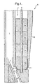
- a tool for excavating an object is schematically shown in longitudinal section in Fig. 1 .
- the tool can be connected to the lower end of a drill string (not shown) extending into a borehole formed in an object such as an earth formation.
- the tool is arranged to jet a stream of drilling fluid mixed with abrasive particles against the object to be excavated and to recirculate at least part of the abrasive particles.
- the abrasive particles must be magnetisable for this tool.
- the tool is provided with a longitudinal drilling fluid passage 1, which is at one end thereof in fluid communication with a drilling fluid channel provided in the drill string and at the other end thereof in fluid communication with a mixing chamber 2 via a drilling fluid inlet 3.
- the mixing chamber 2 is also in fluid communication with an abrasive particle inlet 4 for abrasive particles, and with a mixing nozzle 5 having an outlet (not shown) arranged to jet a stream of drilling fluid and abrasive particles against the earth formation during drilling with the drilling tool in the borehole.
- the mixing chamber is provided with a body of magnetic material 14 on the side opposite from the abrasive particle inlet 4, but this is optional.
- the mixing nozzle is arranged inclined relative to the longitudinal direction of the drilling tool at an inclination angle of 15-30° relative to vertical, but other angles can be used.
- the inclination angle is about 21° which is optimal for abrasively eroding the bottom of the bore hole by axially rotating the complete tool inside the bore hole.
- the mixing chamber 2 and mixing nozzle 5 are aligned with the outlet nozzle under the same angle, in order to achieve optimal acceleration of the abrasive particles.
- the drilling fluid passage 1 is arranged to bypass a device 6 for transporting magnetic particles that is included in the tool as part of a recirculation system for the magnetic abrasive particles which can be used if the abrasive particles contain a magnetic material.
- the device 6 includes a support member in the form of a slightly tapered sleeve 15 for providing a support surface extending around an essentially cylindrically shaped elongate separator magnet 7.
- the separator magnet 7 generates a magnetic field for retaining the magnetic particles on the support surface 15.
- the drilling fluid passage 1 is fixedly arranged relative to the support surface 15 and the mixing chamber 2.
- the drilling fluid passage 1 has a lower end arranged near the abrasive particle inlet 4.
- the drilling fluid passage 1 is formed inside a ridge in the axial direction which ridge is in protruding contact with the support surface 15.
- the drilling fluid passage 1 may alternatively be arranged freestanding from the support surface in a manner similar to that shown and described in International Publication WO 02/34653 with reference to Fig. 4 therein, or in a off-axial direction.
- the abrasive particle inlet 4 for abrasive particles is located at the lower end of the ridge.
- the cylindrical separator magnet 7 is formed of four smaller magnets 7a, 7b, 7c, and 7d stacked together. A different number of the smaller magnets can also be used. Each magnet 7a, 7b, 7c, and 7d has diametrically opposed N and S poles, and the magnets are stacked in a manner that adjacent magnets have N-S directions azimuthally rotated with respect to each other about the central longitudinal axis 8 over an angler ⁇ such that two essentially helical diametrically opposing bands are each formed by alternating N and S poles.
- the magnetic field strength in the regions between the N and S poles in each of the smaller magnets 7a, 7b, 7c, and 7d is lower than in the essentially helically aligned regions around the N and S poles.
- the helical bands of alternating N and S poles form a high-field band of increased magnetic field strength relative to regions forming low-field band displaced by about 90° in azimuth with respect to that high-field band.
- the separator magnet 7 has a central longitudinal axis 8 and is rotatable relative to the sleeve 15 and about the central longitudinal axis 8.
- Drive means are provided (not shown) to drive axis 8 and thereby rotate the separator magnet 7 into either clockwise or counter clockwise rotation as dictated by the sense of the helical band.
- the drive means may advantageously be provided in the form of an electric motor, which motor may be controlled by a control system (not shown).
- a short tapered section 11 is provided at the lower end of magnet 7d.
- the sleeve 15 is provided with a corresponding conical taper in a manner that the abrasive particle inlet 4 for abrasive particles provides fluid communication between the support surface 15 surrounding the tapered section 11 and the mixing chamber 2.
- the conical taper is best based on the same angle as the above-discussed angle of the mixing chamber 2 and mixing nozzle 5.
- the tool works as follows.
- the tool is connected to the lower end of a drill string that is inserted from the surface into a borehole.
- a stream of drilling fluid is pumped by a suitable pump (not shown) at surface, via the drilling fluid channel of the drill string and the fluid passage 1 into the mixing chamber 2.
- the stream is provided with a low concentration of abrasive particles of magnetic material such as steel shot or steel grit.
- the stream flows from the mixing chamber 2 to the mixing nozzle 5 and is jetted against the borehole bottom. Simultaneously the drill string is rotated so that the borehole bottom is evenly eroded.
- a return stream containing the fluid, the abrasive particles and excavation debris, flows from the borehole bottom through the borehole in a direction back to the surface. Thereby, the return stream passes along the sleeve 15.
- the separator magnet 7 is rotated about its axis 8, in a direction dictated by the sense of the helical bands, which can be either clockwise or counter clockwise.
- the separator magnet 7 induces a magnetic field extending to and beyond the outer surface of the sleeve 15.
- the abrasive particles in the stream are separated out from the stream by the magnetic forces from the separator magnet 7 which attract the particles onto the outer surface of the sleeve 15.
- the stream of drilling fluid which is now substantially free from abrasive magnetic particles, flows further through the bore hole to the pump at surface and is re-circulated through the drill string after removal of the drill cuttings.
- the magnetic forces exerted to the abrasive particles are lower in the low-field band than in the high-field band.
- the magnetic particles retained on the support surface 15 are attracted towards the band having the highest magnetic field. Due to rotation of the separator magnet 7 in a direction against the sense of the helical bands, the respective bands and the gradient zone in between exert a force to the magnetic particles in a direction perpendicular to the gradient zone, which has a downward component, thereby forcing the particles to follow a helically downward movement.
- the stream of drilling fluid flowing into the mixing chamber 2 again entrains the particles.
- the particles Once inside the mixing chamber 2, the particles interact with the stream of drilling fluid passing through the mixing chamber 2 from inlet 3 to mixing nozzle 5, and thereby these particles will be entrained by this stream.
- the magnetic body 14 on the side opposite from the abrasive particle inlet 4 causes magnetic field lines to run from the lower end 11 of the separator magnet to this magnetic body.
- the magnetic field gradient from the support surface 15 towards the inside of the mixing chamber 2 becomes less strong, such that entry of the magnetic abrasive particles through abrasive particle inlet 4 into the mixing chamber 2 is facilitated.
- abrasive particles are again jetted against the borehole bottom and subsequently flow through the annulus formed by the tool and the borehole, in the direction to the surface.
- the cycle is then repeated continuously. In this manner it is achieved the drill string/pumping equipment is substantially free from damage by the abrasive particles as these circulate through the lower part of the drill string only, while the drilling fluid circulates through the entire drill string and pumping equipment. In case a small fraction of the particles flows through the borehole to surface, such fraction can again be replaced via the stream of fluid flowing through the drill string.
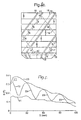
- the separator magnet 7 is also shown in Fig. 2 , in a representation wherein the cylindrical surface is unrolled flat in the plane of the paper.
- vertically is set out the height of the separator magnet, which is divided in smaller magnets 7a, 7b, 7c, and 7d, and horizontally the surface at all azimuths between 0 and 360° is visible.
- the angle ⁇ in this case is 90° in respect of every one of the smaller magnets in the stack, ⁇ being the azimuth angle difference between the projected N-S directions in two neighbouring smaller magnets.
- the angle ⁇ can be varied along the magnet stack.
- Areas 16 schematically indicate where in the gradient zones the magnetic field strength decreases most steeply from the increased value in the high-field band to the value in the low-field band.
- each of the two high-field bands stretches in a direction making an angle ⁇ with respect to the plane perpendicular to the central longitudinal axis as is indicated in Fig. 2 .
- the angle ⁇ can vary along the magnetic stack.
- Magnetic particles retained on the support surface by the separator magnet tend to arrange themselves in elongate chains along a magnetic path from one pole to the nearest pole of opposite polarity.
- Such chains 45 are visible in Fig. 3 , wherein three photographs 3A, 3B and 3C are shown of increasing amounts of steel shot retained on the support surface 15 housing the helical separator magnet.
- the steel shot arranges itself in chains 43 along the helical high-field band having NNSS poles.
- the chains 43 between the N and S poles lie flat on the support surface 15. Chains of shot in the middle of an N or S pole stick out of the support surface since the poles correspond to sources or drains of magnetic field lines.
- the shortest magnetic path on the approximately cylindrical surface between two adjacent N- and S-pole locations within one high-field band is shorter than the shortest path across the approximately cylindrical surface between a S-pole (or N-pole) location in that high-field band and the nearest N-pole (S-pole) location in another high-field band.
- the magnetic particles will tend to form a chain along line 9 in alignment with a high-field band.
- dotted line 10 is indicated having the same path length as dotted line 9 and it can be seen that this dotted line 10 is too short to bridge the distance from the N pole in the high-field band to the nearest S pole outside the band crossing the gradient zone 16.
- the relevant distances are determined on the support surface, since that is approximately the distance over which the chains of particles would grow.
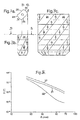
- Figs. 4a, 4b , and 4c show alternative magnet arrangements in accordance with the invention, also for counter clockwise rotation.
- the embodiment shown in Fig. 4a is similar to the one of Fig. 2 , but with the smaller magnets having a smaller size in the stacking direction along the longitudinal axis relative to the lateral size in the plane perpendicular to the stacking direction.
- the poles within a band are not arranged alternatingly with each smaller magnet, but each time two poles of the same type are arranged adjacent to each other.
- This embodiment is thus based on the stack of the four smaller magnets 7a, 7b, 7c, 7d, of Fig. 2 , with the modification that each of the four smaller magnets is divided into two or more even smaller magnets (in the example of Fig. 4b the four smaller magnets are divided into two even smaller magnets 7a1 and 7a2; 7b1 and 7b2; 7c1 and 7c2; 7d1 and 7d2) of which the individual poles are azimuthally displaced with respect to each other.
- the magnetic poles (in the sense of an area appearing as a source or a sink for magnetic field lines) are assembled from groups of individual poles, whereby an individual pole is defined as a spot within a magnetic pole where the field line density reaches a maximum.
- the individual poles are also arranged in a helically shaped manner, preferably coincident with the helical arrangement of the band, so that the magnetic poles themselves get a pseudo-helical appearance.
- Fig. 4c is a hybrid form combining elements from Fig. 4a and Fig. 4b .
- the individual poles appear in the order of NSSNNSSN or SNNSSNNS. This has the advantage that in the middle portion of the separator magnet, the poles formed by neighbouring N-N and S-S pole combinations are pseudo-helically shaped in conformity with the helical arrangement of the band.
- the magnetic poles formed by the first and last of the smaller magnets in the stack are smaller in the stacking direction than the magnetic poles in the middle portion of the separator magnet.
- This has the advantage that the magnetic path from the top most or the bottom most magnetic pole in the high-field band can find its nearest magnetic pole of opposite polarity in the same high-field band, whereas in the case of Fig. 4b this condition is not always fulfilled for the first and last individual poles.
- the first and last of the smaller magnets in the axial stack have a smaller axial height than the smaller magnets in a middle portion of the separator magnet.
- Fig. 5 shows calculations of the magnetic field strength B (in Tesla) on the support surface 15 of a conically tapered support member such as is depicted in Fig. 1 , that is generated by a cylindrical separator magnet 7 of which the smaller magnets are arranged in accordance with Fig. 4c .
- the magnetic field strength is plotted against the vertical axis, and the axial height parallel to the magnet axis 8 is plotted against the horizontal axis.
- the dimensional parameters are given in Table I.
- Table I Part name Reference number size Axial length of separator magnet 7 120 mm Outer diameter of separator magnet 7 29 mm Diameter in lower part of support surface 15 34 mm Diameter in upper part of support surface 15 52 mm
- Line 20 in Fig. 5 corresponds to the magnetic field strength found along a helical path within the high-field band of increased magnetic field strength, which path is depicted by the dashed lines 17 in Fig. 4c . It can be seen that the field strength generally increases. This is a result of the decreasing gap width between the outer magnet surface and the support surface 15 as a function of position on the helical high-field band.
- Line 21 in Fig. 5 corresponds to the magnetic field strength found along a helical path within the low-field band (which in this example is displaced 90° from path 17 in azimuthal direction), which path is depicted by the dashed lines 18 in Fig. 4c .
- the magnetic field strength in the low-field band is found to be approximately half that of the high-field band, which is a result of the nature of the bipolar smaller magnets. It can also be seen that the field strength generally increases. This is a result of the decreasing gap width between the outer magnet surface and the support surface 15.
- Line 22 in Fig. 5 corresponds to the magnetic field strength found along an anti-helical path, which path is depicted by the dashed lines 19 in Fig. 4c . This path crosses the above-mentioned paths 17 and 18, and the magnetic field strength oscillates between the values given in the high- and low-field bands.
- Reference number 23 indicates the gradient zones that exert the driving force that causes the desired transport of the magnetic particles, when the gradient zones are being advanced relative to the support surface.
- line 22 in Fig. 5 shows a generally increasing magnetic field strength with smaller axial height, which is a result of the decreasing gap width between the outer magnet surface and the support surface. This provides a significant additional force component on the magnetic particles in the axial direction, which enhances the transport of the particles in that direction.
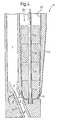
- Fig. 6 shows a device similar to the device shown in Fig. 1 .
- the separator magnet 37 and the inside wall 35 of the support sleeve 15 are slightly different from the embodiment of Fig. 1 , in that both the outer diameter of the separator magnet 37 and the inner diameter of the inside wall 35 reduce with decreasing axial height.
- the smaller magnets 37a to 37d are of a frustoconical shape to obtain the tapered shape of the separator magnet 37.
- the gap between the separator magnet 37 and the inside wall 35 of the support sleeve 15 decreases, as well as the wall thickness of the support sleeve.
- An advantage of this embodiment is that the capture length to be overcome by the separator magnet is reduced compared to the bore hole. Moreover, the total magnetic energy in the separator magnet can be increased to increase the capture efficiency.
- the shape of the optional body of magnetic material 34 which here appears as a pellet located on the side opposite from the abrasive particle inlet 4.
- This type can also be utilized in an embodiment of the device having a cylindrical separator magnet.
- the magnetic particles follow a helical path along the support surface in a downward direction perpendicular to the helical bands.
- the downward axial component of the velocity of transport is proportional to the rotational speed of the separator magnet times sin ( ⁇ ) times cos ( ⁇ ) where ⁇ is the angle between the helical gradient zone and the plane perpendicular to the axis of rotation which coincides with the central longitudinal axis of the separator magnet 7 as is indicated in Fig. 2 .
- a good range for operating is 32° to 58°, within which range the downward component of the velocity is more than 90% of the possible maximum.
- the drilling fluid bypass guide 1 is formed in a ridge in the axial direction in contact with the support surface 15. This ridge deflects the magnetic particles moving on the support surface 15 in a downward helical path and forces them to move in axial direction along the side of the ridge in a straight path towards the abrasive particle inlet opening 4 of the mixing chamber 2.
- the drilling fluid passage 1 acts as a guide means to guide magnetic abrasive particles retained on the support surface 15 to the abrasive particle inlet 4 for abrasive particles.
- This arrangement has the advantage that the transport of the magnetic particles to the abrasive particle inlet opening 4 can be faster than when the magnetic particles follow the downward helical trajectory.
- the downward axial component of the velocity of transport is now proportional to the rotational speed of the separator magnet divided by tan ( ⁇ ).
- ⁇ the rotational speed of the separator magnet divided by tan
- ⁇ should preferably be within the range of 40° to 60°, more preferably between 45° and 60°, and most preferably between 45° and 55°.
- the device for transporting particles comprises one or more relatively short essentially axially oriented ridge sections are provided onto the support surface whereby the support surface extends beyond the ridge sections in the direction of the ridge sections.
- a more homogeneous distribution of the magnetic particles over the support surface is achieved as well as an improvement of the axial transport velocity of the magnetic particles over the support surface.
- the high- and low-field bands were formed by virtue of the field distribution of bipolar cylindrical magnets. This results in bands of increased magnetic field strength. Magnetic particles retained on the support surface react most directly to the advancement of the gradient zone if the change in the magnetic field in the gradient zone is large.
- the low-field band preferably corresponds to a region of reduced magnetic permeability of the separator magnet and/or a gap between the separator magnet and the support surface. Herewith a more abrupt gradient zone between high- and low-field bands is achieved.
- Fig. 7 shows an embodiment wherein the region of reduced magnetic permeability is provided in the form of a helical recess 26 in the outer surface of the separator magnet 7 adjacent to the high-field band. Due to the higher magnetic permeability of the magnet material than the less magnet material that fills up the recesses (a gas, a fluid, or a solid) the internal magnetic field lines predominantly follow the material of the magnet rather than the material contained in the recess. This makes the high-field band of increased magnetic field strength, adjacent the recess 26, more pronounced.
- Fig. 7a shows a cross section of the separator magnet, which shows circular contours 24 around the diametrically opposing poles, connected by essentially straight contours 25. The straight contours correspond with the recess 26 and the circular contours with the high-field bands of increased magnetic field strength.
- Fig. 7b a schematic longitudinal view is provided of the separator magnet, whereby the slanted phantom lines indicate the transition between the circular contours and the essentially straight contours.
- Fig. 7c provides a schematic representation of the entire surface in the same way as in Fig. 2 .
- the angle ⁇ of the helical recess is 53°.
- the recess reaches a depth with respect to the cylindrical circumference of the separator magnet that is similar as or greater than the distance between the gap between the magnetic surface in the high-field band and the support surface.
- Suitable magnets for the device for transporting particles of a magnetic material and for the described recirculation system can be made from any highly magnetisable material, including NdFeB, SmCo and AlNiCo-5, or a combination thereof.
- the separator magnet also has a magnetic energy content of at least 140 kJ/m 3 at room temperature, preferably more than 300 kJ/m 3 at room temperature such as is the case with NdFeB-based magnets.
- a high energy content allows for shorter axial contact length of the support surface with the return stream, and consequently a stronger taper of the support surface which is advantageous for the axial transport rate. Also, less power is required for the rotation of the separator magnet.
- the sleeve 15 and the drilling fluid bypass 1 are normally made of a non-magnetic material. They are suitably machined out of a single piece of the material in order to obtain optimal mechanical strength.
- Super alloys including high-strength corrosion resistant non-magnetic Ni-Cr alloys including one sold under the name Inconel 718 or Allvac 718, have been found to be particularly suitable.
- Inconel 718 is a precipitation hardenable alloy having a composition within ranges given in Table II. Other materials can be used, including BeCu. Table II: composition Inconel 718 in wt.% Element Min. Max.
- the electric resistivity of the material is preferably higher than 50 ⁇ cm.
- a sleeve can be made, sufficiently thick for down-hole application, whereby the additional torque, up to a rotary frequency of 10 Hz of the separator magnet 7, approaches the torque necessary to overcome the friction of a normal amount of abrasive particles on the support surface.
- the resistivity is higher than 100 ⁇ cm, to enable a higher frequency of about 40 Hz.
- Inconel 718 has a resistivity of approximately 122 ⁇ cm, which in a tool of the size as given in Table I has been calculated and measured to result in a torque of 6 Ncm at 15 Hz.
- Fig. 8 shows on a log-log plot the calculated radial decay of the magnetic field for the separator magnet of Fig. 4b (curve 30), for the separator magnet of Fig. 4c (curve 31), and for the separator magnet of Fig. 4a (curve 32).
- On the horizontal scale is plotted the radial distance from the magnet axis and on the vertical scale the magnetic field.
- magnets with, on average, larger magnetic poles (a pole arrangement such as in Figs. 4b and 4c ) of the same polarity (in axial direction) have a longer magnetic reach than magnets with shorter magnetic poles (a pole arrangement such as in Fig. 4a ).
- Fig. 9 shows a schematic view of a tool for excavating an object, including a recirculation system as described above. Visible are the conically shaped support surface 15 housing the separator magnet, and the ridge 41 housing the bypassing drilling fluid passage. This ridge is also visible in Fig. 3 . The dimensions correspond to those given in Table I.
- filtering means are optionally provided in the form of a skirt 43, shielding the abrasive particle inlet 4 from the annulus and creating an opening 44 in the form of a slit between the skirt 43 and support surface 15.
- the support surface 15 and the inside surface of skirt 43 define a passage channel connecting the abrasive particle inlet 4 with the bore hole annulus. This skirt arrangement avoids that rock grains larger than the size of the access window of abrasive particle inlet 4 enter the passage channel.
- This arrangement of the skirt 43 also guides the flow of drilling fluid from the bore hole annulus to the mixing chamber 2, along the support surface 15 in the direction of the desired transport.
- the velocity of the drilling fluid in the bore hole annulus should preferably not exceed 3 m/s.
- additional slots or openings are provided in the skirt wall on the annular side.
- the skirt 43 as it appears in Figs. 3 and 9 is suitable for use in combination with a counter clockwise rotatable separator magnet. It will be clear that for a tool with a clockwise rotatable separator the skirt must be provided on the other side of the abrasive particle inlet.
- a jet pump mechanism in the mixing nozzle 5 generates a strong flow of drilling fluid from the mixing chamber 2 to the mixing nozzle 5.
- the jet pump mechanism auxiliarily supports the flow of magnetic particles into the mixing chamber 2.
- a larger diameter of the mixing nozzle 5 compared to a drilling fluid inlet nozzle (between inlet 3 and the mixing chamber 2) results in adequate entrainment of drilling fluid and the magnetic abrasive particles entering into the mixing chamber via abrasive particle inlet 4.
- the interaction between the entrained drilling fluid and the magnetic particles contributes to the efficiency of the release of particles from the support surface 15 into the mixing chamber 2 as well.
- the return stream of drilling fluid in the bore hole annulus may pass the recirculation system at a velocity of 2 m/s or even higher.
- the reach of the magnetic field into the bore hole annulus should exert a pulling force on the particles sufficiently strong to pull them to the support surface before they have passed the device.
- the magnetic force pulling the particles onto the housing should be as low as possible in order to minimise friction forces and power requirements for rotating the separator magnet.
- the most suitable separator magnet is one that has an as high as possible coefficient for the lowest dominant radial polar moment, which is typically a separator magnet having a dominant dipole behaviour over a quadrupole behaviour for a certain energy content.
- the separator magnet is preferably located in the axial centre of the bore hole. In a typical bore hole, a small axial offset of up to 15% of the diameter of the excavation tool is acceptable.
- the embodiment shown in Fig. 9 has an axial offset of the separator magnet contained axially inside the support surface 15 of 10%, or approximately 7 mm for a targeted 70 mm diameter bore hole.
- the drilling fluid in the mixing mixing nozzle 5, or in the abrasive jet may contain a concentration of typically up to 10% by volume of magnetic abrasive particles.
- a typical concentration of magnetic abrasive particles that is supplied via the bypass conduit 1 lies between 0.1 and 1% by volume.
- the separator magnet is typically driven at a rotational frequency of between 10 and 40 Hz.
Abstract
Claims (14)
- Un outil pour l'excavation d'un objet, l'outil comprenant un système de projection de jets (2, 3, 4, 5) disposé pour projeter un impact sur l'objet à dégager avec un jet de liquide mélangé à des particules abrasives, notamment une matière magnétique, le système de projection étant fourni avec au moins un orifice d'entrée de particules abrasives (4), assurant l'entrée de ces particules dans le système, l'outil comportant en outre un système de recyclage (7, 8, 15) conçu pour recycler au moins une partie des particules abrasives en provenance d'un flux de retour du liquide mélangé aux particules abrasives d'impact en aval du flux projeté avec l'objet, jusqu'au système de projection, le système de recyclage (7, 8, 15) comportant un dispositif de transport de particules contenant une matière magnétique dans un sens choisi, le dispositif comportant :- une pièce de support ayant une surface de support (15) pour supporter les particules, la surface de support (15) s'étendant dans le sens choisi ;- un aimant de séparation (7) disposé pour générer un champ magnétique afin de retenir les particules sur la surface de support (15), le champ magnétique sur la surface de support étant disposé pour avoir une bande à haute intensité de champ (17), une bande à faible intensité de champ (18) et un gradient de champ magnétique dans une zone de gradient (16) entre lesdites bandes à haute et faible intensités au moyen duquel la force du champ magnétique dans la bande de haute intensité (17) est plus élevée que dans la bande à faible intensité (18) ;- moyens (8) pour avancer les bandes à haute intensité et à faible intensité de champ (17, 18) par rapport à la surface de support dans un sens ayant un composant en direction du gradient de champ magnétique sur la surface de support, la bande à haute intensité de champ (17) étant suivie de la bande à faible intensité de champ (18), où, le long de ladite bande à haute intensité de champ, au moins un premier pôle magnétique et un second pôle magnétique, de signes opposés, sont disposés de telle sorte qu'un premier chemin magnétique (12) sur la surface de support entre le premier pôle magnétique et le second pôle magnétique, soit plus court qu'un deuxième champ magnétique (13) sur la surface de support croisant la zone de gradient (16) entre le premier pôle magnétique et tout autre pôle magnétique le plus proche de signe opposé ;où la surface de support (15) est exposée audit flux de retour de transport des particules abrasives du flux de retour vers l'orifice d'entrée (4).
- L'outil de la revendication 1, où l'aimant de séparation (7) est un aimant composite comportant plusieurs composants aimantés (7a, 7b, 7c, 7d) empilés ensemble dans un sens d'empilage choisi.
- L'outil de la revendication 3 dans lequel chacun des composants aimantés (7a, 7b, 7c, 7d) a un axe projeté N-S formé par un composant d'un champ magnétique interne le long d'une perpendiculaire plane au sens choisi d'empilage.
- L'outil de la revendication 3 où les axes projetés N-S des composants magnétiques empilés (7a, 7b, 7c, 7d) croisent la bande à haute intensité de champ.
- L'outil de la revendication 4 où le premier pôle magnétique et le second pôle magnétique sont chacun formés par des groupes de pôles individuels (N, S) d'un ou de plusieurs composants magnétiques empilés (7a, 7b, 7c, 7d).
- L'outil de la revendication 4 où le premier et/ou le second pôle magnétique est/sont formé(s) de plusieurs composants magnétiques empilés (7a, 7b, 7c, 7d).
- L'outil d'une des revendications précédentes, où lesdits moyens d'avancement des bandes (17, 18) par rapport à la surface du support dans le sens ayant le composant dans la direction du gradient de champ magnétique sur la surface de support, sont fournis sous la forme de moyens (8) d'entraînement de la rotation de l'aimant de séparation (7) autour d'un axe parallèle au sens choisi d'empilage par rapport à la surface de support (15).
- L'outil d'une des revendications précédentes où la zone de gradient (16) est disposée de manière hélicoïdale autour de l'aimant de séparation (7).
- L'outil d'une des revendications précédentes, où la bande à faible intensité de champ (18) correspond à un évidement (26) dans la surface extérieure de l'aimant de séparation (7).
- L'outil d'une des revendications précédentes, où le champ magnétique dans la zone de gradient (16) augmente généralement sur une trajectoire sur la surface de support (15) dans le sens choisi de transport.
- L'outil d'une des revendications précédentes, où la surface de support (15) s'étend autour de l'aimant (7) laissant une distance entre la surface de support et la surface extérieure de l'aimant de séparation (7), par laquelle ladite distance sur le premier site de la surface de support est plus petite que la distance sur le second site de la surface de support, le premier site étant en aval dans le sens choisi par rapport au second site.
- L'outil de la revendication 11, où la surface de support (15) est disposée en pointe autour de l'aimant de séparation (7).
- L'outil de la revendication 1, où la surface de support (15) est fournie avec une arête (41) sur la surface de support (15), guidant les particules abrasives vers le deuxième orifice d'entrée.
- L'outil de la revendication 1, où le système de projection de jets est connecté par liquide à un conduit de dérivation (1) disposé dans l'arête (41) pour alimenter le système de projection avec le liquide.
Priority Applications (1)
| Application Number | Priority Date | Filing Date | Title |
|---|---|---|---|
| EP04741976A EP1649129B1 (fr) | 2003-07-09 | 2004-07-08 | Outil de coupe comportant un dispositif servant a transporter des particules d'un materiau magnetique |
Applications Claiming Priority (4)
| Application Number | Priority Date | Filing Date | Title |
|---|---|---|---|
| EP03077159 | 2003-07-09 | ||
| EP04101507 | 2004-04-14 | ||
| PCT/EP2004/051407 WO2005005766A1 (fr) | 2003-07-09 | 2004-07-08 | Dispositif servant a transporter des particules d'un materiau magnetique et outil comportant un tel dispositif |
| EP04741976A EP1649129B1 (fr) | 2003-07-09 | 2004-07-08 | Outil de coupe comportant un dispositif servant a transporter des particules d'un materiau magnetique |
Publications (2)
| Publication Number | Publication Date |
|---|---|
| EP1649129A1 EP1649129A1 (fr) | 2006-04-26 |
| EP1649129B1 true EP1649129B1 (fr) | 2009-09-16 |
Family
ID=34066507
Family Applications (1)
| Application Number | Title | Priority Date | Filing Date |
|---|---|---|---|
| EP04741976A Not-in-force EP1649129B1 (fr) | 2003-07-09 | 2004-07-08 | Outil de coupe comportant un dispositif servant a transporter des particules d'un materiau magnetique |
Country Status (15)
| Country | Link |
|---|---|
| US (1) | US7431104B2 (fr) |
| EP (1) | EP1649129B1 (fr) |
| AR (1) | AR045021A1 (fr) |
| AT (1) | ATE443198T1 (fr) |
| AU (1) | AU2004256235B2 (fr) |
| BR (1) | BRPI0412381A (fr) |
| CA (1) | CA2531330C (fr) |
| DE (1) | DE602004023203D1 (fr) |
| EA (1) | EA008120B1 (fr) |
| EG (1) | EG24109A (fr) |
| MX (1) | MXPA06000233A (fr) |
| MY (1) | MY137593A (fr) |
| NO (1) | NO20060618L (fr) |
| OA (1) | OA13219A (fr) |
| WO (1) | WO2005005766A1 (fr) |
Families Citing this family (16)
| Publication number | Priority date | Publication date | Assignee | Title |
|---|---|---|---|---|
| AR045022A1 (es) | 2003-07-09 | 2005-10-12 | Shell Int Research | Sistema y metodo para perforar un objeto |
| CA2531334C (fr) | 2003-07-09 | 2012-08-21 | Shell Canada Limited | Separateur de particules magnetique concu pour un systeme a jets de particules abrasives |
| AR045021A1 (es) | 2003-07-09 | 2005-10-12 | Shell Int Research | Dispositivo para el transporte de particulas magneticas y la herramienta que incluye dicho dispositivo |
| AU2004256234B2 (en) * | 2003-07-09 | 2007-12-13 | Shell Internationale Research Maatschappij B.V. | Tool for excavating an object |
| US7445058B2 (en) | 2003-10-21 | 2008-11-04 | Shell Oil Company | Nozzle unit and method for excavating a hole in an object |
| US7419014B2 (en) | 2003-10-29 | 2008-09-02 | Shell Oil Company | Fluid jet drilling tool |
| WO2007057426A2 (fr) | 2005-11-18 | 2007-05-24 | Shell Internationale Research Maatschappij B.V. | Dispositif et procede de distribution de particules dans un courant |
| WO2007133259A1 (fr) | 2006-04-18 | 2007-11-22 | Gambro Bct, Inc. | Dispositif de traitement de sang extracorporel avec équilibrage de pompes |
| CN102667047B (zh) | 2009-12-23 | 2015-11-25 | 国际壳牌研究有限公司 | 钻井方法和喷射钻井系统 |
| WO2011076851A1 (fr) | 2009-12-23 | 2011-06-30 | Shell Internationale Research Maatschappij B.V. | Procédé de forage et ensemble de forage à jet abrasif |
| WO2011076847A1 (fr) | 2009-12-23 | 2011-06-30 | Shell Internationale Research Maatschappij B.V. | Procédé de forage d'un trou de forage et train de tiges de forage hybride |
| AU2010334862B2 (en) | 2009-12-23 | 2015-09-03 | Shell Internationale Research Maatschappij B.V. | Method of drilling and jet drilling system |
| BR112012015436A2 (pt) | 2009-12-23 | 2016-03-15 | Shell Int Research | método para determinar uma propriedade de um material de formação no curso de uma operação de perfuração por jato |
| CN103731967A (zh) * | 2014-01-21 | 2014-04-16 | 中国科学院电工研究所 | 一种等离子体背场增强轨道 |
| RU2640445C1 (ru) * | 2016-11-29 | 2018-01-09 | Федеральное государственное автономное образовательное учреждение высшего образования "Национальный исследовательский Томский политехнический университет" | Способ шароструйного бурения скважин |
| NL2024001B1 (en) | 2019-10-11 | 2021-06-17 | Stichting Canopus Intellectueel Eigendom | Method and system for directional drilling |
Family Cites Families (19)
| Publication number | Priority date | Publication date | Assignee | Title |
|---|---|---|---|---|
| US3375886A (en) * | 1963-09-24 | 1968-04-02 | Gulf Research Development Co | Method of treating abrasive-laden drilling liquid |
| US3489280A (en) * | 1966-02-03 | 1970-01-13 | Eriez Mfg Co | Magnetic separator having field shaping poles |
| DE2052516A1 (fr) * | 1970-10-26 | 1972-04-27 | Sellnow W | |
| US3831753A (en) * | 1972-12-18 | 1974-08-27 | Gulf Research Development Co | Slotted in-line screen |
| JPS50125368A (fr) * | 1974-03-22 | 1975-10-02 | ||
| DE2832037A1 (de) | 1978-07-21 | 1980-01-31 | Canon Kk | Foerdereinrichtung fuer ferromagnetisches material |
| SU924334A1 (ru) | 1980-11-24 | 1982-04-30 | Kb Polt Inst Kujbysheva | Разделитель промывочной жидкости при эрозионном бурении скважин 1 |
| US4993503A (en) * | 1990-03-27 | 1991-02-19 | Electric Power Research Institute | Horizontal boring apparatus and method |
| US5170891A (en) * | 1991-09-20 | 1992-12-15 | Venturedyne Limited | Self-cleaning magnetic separator |
| GC0000132A (en) * | 1999-04-28 | 2005-06-29 | Shell Int Research | Abrasive jet drilling assembly. |
| US6702940B2 (en) * | 2000-10-26 | 2004-03-09 | Shell Oil Company | Device for transporting particles of magnetic material |
| US6412643B1 (en) * | 2001-02-21 | 2002-07-02 | Robert T. Wysolmierski | Ferrous particle magnetic removal and collection apparatus |
| MY136183A (en) * | 2001-03-06 | 2008-08-29 | Shell Int Research | Jet cutting device with deflector |
| CA2531334C (fr) | 2003-07-09 | 2012-08-21 | Shell Canada Limited | Separateur de particules magnetique concu pour un systeme a jets de particules abrasives |
| AU2004256234B2 (en) | 2003-07-09 | 2007-12-13 | Shell Internationale Research Maatschappij B.V. | Tool for excavating an object |
| AR045022A1 (es) | 2003-07-09 | 2005-10-12 | Shell Int Research | Sistema y metodo para perforar un objeto |
| AR045021A1 (es) | 2003-07-09 | 2005-10-12 | Shell Int Research | Dispositivo para el transporte de particulas magneticas y la herramienta que incluye dicho dispositivo |
| WO2005038189A1 (fr) | 2003-10-21 | 2005-04-28 | Shell Internationale Research Maatschappij B.V. | Unite a buses et procede permettant de creuser un trou dans un objet |
| WO2005040546A1 (fr) | 2003-10-29 | 2005-05-06 | Shell Internationale Research Maatschappij B.V. | Outil de forage a jet de fluide |
-
2004
- 2004-07-06 AR ARP040102373A patent/AR045021A1/es unknown
- 2004-07-07 MY MYPI20042708A patent/MY137593A/en unknown
- 2004-07-08 AU AU2004256235A patent/AU2004256235B2/en not_active Ceased
- 2004-07-08 CA CA2531330A patent/CA2531330C/fr not_active Expired - Fee Related
- 2004-07-08 MX MXPA06000233A patent/MXPA06000233A/es not_active Application Discontinuation
- 2004-07-08 OA OA1200600006A patent/OA13219A/en unknown
- 2004-07-08 US US10/563,887 patent/US7431104B2/en not_active Expired - Fee Related
- 2004-07-08 EP EP04741976A patent/EP1649129B1/fr not_active Not-in-force
- 2004-07-08 WO PCT/EP2004/051407 patent/WO2005005766A1/fr active Search and Examination
- 2004-07-08 BR BRPI0412381-6A patent/BRPI0412381A/pt active Search and Examination
- 2004-07-08 EA EA200600210A patent/EA008120B1/ru not_active IP Right Cessation
- 2004-07-08 AT AT04741976T patent/ATE443198T1/de active
- 2004-07-08 DE DE602004023203T patent/DE602004023203D1/de active Active
-
2006
- 2006-01-08 EG EGNA2006000018 patent/EG24109A/xx active
- 2006-02-08 NO NO20060618A patent/NO20060618L/no not_active Application Discontinuation
Also Published As
| Publication number | Publication date |
|---|---|
| EP1649129A1 (fr) | 2006-04-26 |
| OA13219A (en) | 2006-12-13 |
| EA200600210A1 (ru) | 2006-06-30 |
| US7431104B2 (en) | 2008-10-07 |
| MY137593A (en) | 2009-02-27 |
| US20060185907A1 (en) | 2006-08-24 |
| AU2004256235B2 (en) | 2007-09-13 |
| WO2005005766A1 (fr) | 2005-01-20 |
| BRPI0412381A (pt) | 2006-09-19 |
| ATE443198T1 (de) | 2009-10-15 |
| NO20060618L (no) | 2006-03-22 |
| DE602004023203D1 (de) | 2009-10-29 |
| CA2531330C (fr) | 2012-06-12 |
| AU2004256235A1 (en) | 2005-01-20 |
| MXPA06000233A (es) | 2006-04-11 |
| EA008120B1 (ru) | 2007-04-27 |
| EG24109A (en) | 2008-06-22 |
| AR045021A1 (es) | 2005-10-12 |
| CA2531330A1 (fr) | 2005-01-20 |
Similar Documents
| Publication | Publication Date | Title |
|---|---|---|
| EP1649129B1 (fr) | Outil de coupe comportant un dispositif servant a transporter des particules d'un materiau magnetique | |
| US7493966B2 (en) | System and method for drilling using a modulated jet stream | |
| AU2002221791B2 (en) | Device for transporting particles of magnetic material | |
| AU2002221791A1 (en) | Device for transporting particles of magnetic material | |
| EP1649132B1 (fr) | Outil pour excaver un objet | |
| EP1649130B1 (fr) | Outil pour l'excavation d'un objet | |
| US20100078217A1 (en) | Method and assembly for abrasive jet drilling | |
| EP2516786A1 (fr) | Procédé de forage et ensemble de forage à jet abrasif | |
| CN1833089B (zh) | 用于输送磁性材料的颗粒的装置以及包括这种装置的工具 |
Legal Events
| Date | Code | Title | Description |
|---|---|---|---|
| PUAI | Public reference made under article 153(3) epc to a published international application that has entered the european phase |
Free format text: ORIGINAL CODE: 0009012 |
|
| 17P | Request for examination filed |
Effective date: 20060202 |
|
| AK | Designated contracting states |
Kind code of ref document: A1 Designated state(s): AT BE BG CH CY CZ DE DK EE ES FI FR GB GR HU IE IT LI LU MC NL PL PT RO SE SI SK TR |
|
| DAX | Request for extension of the european patent (deleted) | ||
| 17Q | First examination report despatched |
Effective date: 20060601 |
|
| RTI1 | Title (correction) |
Free format text: CUTTING TOOL COMPRISING A DEVICE FOR TRANSPORTING PARTICLES OF A MAGNETIC MATERIAL |
|
| GRAP | Despatch of communication of intention to grant a patent |
Free format text: ORIGINAL CODE: EPIDOSNIGR1 |
|
| GRAS | Grant fee paid |
Free format text: ORIGINAL CODE: EPIDOSNIGR3 |
|
| GRAA | (expected) grant |
Free format text: ORIGINAL CODE: 0009210 |
|
| AK | Designated contracting states |
Kind code of ref document: B1 Designated state(s): AT BE BG CH CY CZ DE DK EE ES FI FR GB GR HU IE IT LI LU MC NL PL PT RO SE SI SK TR |
|
| REG | Reference to a national code |
Ref country code: GB Ref legal event code: FG4D |
|
| REG | Reference to a national code |
Ref country code: CH Ref legal event code: EP |
|
| REG | Reference to a national code |
Ref country code: IE Ref legal event code: FG4D |
|
| REF | Corresponds to: |
Ref document number: 602004023203 Country of ref document: DE Date of ref document: 20091029 Kind code of ref document: P |
|
| REG | Reference to a national code |
Ref country code: SE Ref legal event code: TRGR |
|
| PG25 | Lapsed in a contracting state [announced via postgrant information from national office to epo] |
Ref country code: FI Free format text: LAPSE BECAUSE OF FAILURE TO SUBMIT A TRANSLATION OF THE DESCRIPTION OR TO PAY THE FEE WITHIN THE PRESCRIBED TIME-LIMIT Effective date: 20090916 |
|
| PG25 | Lapsed in a contracting state [announced via postgrant information from national office to epo] |
Ref country code: SI Free format text: LAPSE BECAUSE OF FAILURE TO SUBMIT A TRANSLATION OF THE DESCRIPTION OR TO PAY THE FEE WITHIN THE PRESCRIBED TIME-LIMIT Effective date: 20090916 Ref country code: PL Free format text: LAPSE BECAUSE OF FAILURE TO SUBMIT A TRANSLATION OF THE DESCRIPTION OR TO PAY THE FEE WITHIN THE PRESCRIBED TIME-LIMIT Effective date: 20090916 |
|
| REG | Reference to a national code |
Ref country code: SK Ref legal event code: T3 Ref document number: E 6481 Country of ref document: SK |
|
| PG25 | Lapsed in a contracting state [announced via postgrant information from national office to epo] |
Ref country code: CY Free format text: LAPSE BECAUSE OF FAILURE TO SUBMIT A TRANSLATION OF THE DESCRIPTION OR TO PAY THE FEE WITHIN THE PRESCRIBED TIME-LIMIT Effective date: 20090916 |
|
| PG25 | Lapsed in a contracting state [announced via postgrant information from national office to epo] |
Ref country code: EE Free format text: LAPSE BECAUSE OF FAILURE TO SUBMIT A TRANSLATION OF THE DESCRIPTION OR TO PAY THE FEE WITHIN THE PRESCRIBED TIME-LIMIT Effective date: 20090916 Ref country code: RO Free format text: LAPSE BECAUSE OF FAILURE TO SUBMIT A TRANSLATION OF THE DESCRIPTION OR TO PAY THE FEE WITHIN THE PRESCRIBED TIME-LIMIT Effective date: 20090916 Ref country code: PT Free format text: LAPSE BECAUSE OF FAILURE TO SUBMIT A TRANSLATION OF THE DESCRIPTION OR TO PAY THE FEE WITHIN THE PRESCRIBED TIME-LIMIT Effective date: 20100118 Ref country code: ES Free format text: LAPSE BECAUSE OF FAILURE TO SUBMIT A TRANSLATION OF THE DESCRIPTION OR TO PAY THE FEE WITHIN THE PRESCRIBED TIME-LIMIT Effective date: 20091227 |
|
| PG25 | Lapsed in a contracting state [announced via postgrant information from national office to epo] |
Ref country code: BE Free format text: LAPSE BECAUSE OF FAILURE TO SUBMIT A TRANSLATION OF THE DESCRIPTION OR TO PAY THE FEE WITHIN THE PRESCRIBED TIME-LIMIT Effective date: 20090916 |
|
| PLBE | No opposition filed within time limit |
Free format text: ORIGINAL CODE: 0009261 |
|
| STAA | Information on the status of an ep patent application or granted ep patent |
Free format text: STATUS: NO OPPOSITION FILED WITHIN TIME LIMIT |
|
| PG25 | Lapsed in a contracting state [announced via postgrant information from national office to epo] |
Ref country code: DK Free format text: LAPSE BECAUSE OF FAILURE TO SUBMIT A TRANSLATION OF THE DESCRIPTION OR TO PAY THE FEE WITHIN THE PRESCRIBED TIME-LIMIT Effective date: 20090916 |
|
| 26N | No opposition filed |
Effective date: 20100617 |
|
| PG25 | Lapsed in a contracting state [announced via postgrant information from national office to epo] |
Ref country code: GR Free format text: LAPSE BECAUSE OF FAILURE TO SUBMIT A TRANSLATION OF THE DESCRIPTION OR TO PAY THE FEE WITHIN THE PRESCRIBED TIME-LIMIT Effective date: 20091217 |
|
| PG25 | Lapsed in a contracting state [announced via postgrant information from national office to epo] |
Ref country code: MC Free format text: LAPSE BECAUSE OF NON-PAYMENT OF DUE FEES Effective date: 20100731 |
|
| REG | Reference to a national code |
Ref country code: CH Ref legal event code: PL |
|
| PG25 | Lapsed in a contracting state [announced via postgrant information from national office to epo] |
Ref country code: CH Free format text: LAPSE BECAUSE OF NON-PAYMENT OF DUE FEES Effective date: 20100731 Ref country code: LI Free format text: LAPSE BECAUSE OF NON-PAYMENT OF DUE FEES Effective date: 20100731 |
|
| PG25 | Lapsed in a contracting state [announced via postgrant information from national office to epo] |
Ref country code: IE Free format text: LAPSE BECAUSE OF NON-PAYMENT OF DUE FEES Effective date: 20100708 |
|
| PG25 | Lapsed in a contracting state [announced via postgrant information from national office to epo] |
Ref country code: LU Free format text: LAPSE BECAUSE OF NON-PAYMENT OF DUE FEES Effective date: 20100708 Ref country code: BG Free format text: LAPSE BECAUSE OF FAILURE TO SUBMIT A TRANSLATION OF THE DESCRIPTION OR TO PAY THE FEE WITHIN THE PRESCRIBED TIME-LIMIT Effective date: 20090916 Ref country code: HU Free format text: LAPSE BECAUSE OF FAILURE TO SUBMIT A TRANSLATION OF THE DESCRIPTION OR TO PAY THE FEE WITHIN THE PRESCRIBED TIME-LIMIT Effective date: 20100317 |
|
| PG25 | Lapsed in a contracting state [announced via postgrant information from national office to epo] |
Ref country code: TR Free format text: LAPSE BECAUSE OF FAILURE TO SUBMIT A TRANSLATION OF THE DESCRIPTION OR TO PAY THE FEE WITHIN THE PRESCRIBED TIME-LIMIT Effective date: 20090916 |
|
| REG | Reference to a national code |
Ref country code: FR Ref legal event code: PLFP Year of fee payment: 12 |
|
| PGFP | Annual fee paid to national office [announced via postgrant information from national office to epo] |
Ref country code: SK Payment date: 20150603 Year of fee payment: 12 |
|
| PGFP | Annual fee paid to national office [announced via postgrant information from national office to epo] |
Ref country code: NL Payment date: 20150709 Year of fee payment: 12 |
|
| PGFP | Annual fee paid to national office [announced via postgrant information from national office to epo] |
Ref country code: CZ Payment date: 20150703 Year of fee payment: 12 Ref country code: DE Payment date: 20150630 Year of fee payment: 12 Ref country code: GB Payment date: 20150708 Year of fee payment: 12 |
|
| PGFP | Annual fee paid to national office [announced via postgrant information from national office to epo] |
Ref country code: SE Payment date: 20150713 Year of fee payment: 12 Ref country code: AT Payment date: 20150625 Year of fee payment: 12 Ref country code: FR Payment date: 20150629 Year of fee payment: 12 |
|
| PGFP | Annual fee paid to national office [announced via postgrant information from national office to epo] |
Ref country code: IT Payment date: 20150727 Year of fee payment: 12 |
|
| PG25 | Lapsed in a contracting state [announced via postgrant information from national office to epo] |
Ref country code: CZ Free format text: LAPSE BECAUSE OF NON-PAYMENT OF DUE FEES Effective date: 20160708 |
|
| REG | Reference to a national code |
Ref country code: DE Ref legal event code: R119 Ref document number: 602004023203 Country of ref document: DE |
|
| REG | Reference to a national code |
Ref country code: NL Ref legal event code: MM Effective date: 20160801 |
|
| REG | Reference to a national code |
Ref country code: SE Ref legal event code: EUG |
|
| REG | Reference to a national code |
Ref country code: AT Ref legal event code: MM01 Ref document number: 443198 Country of ref document: AT Kind code of ref document: T Effective date: 20160708 |
|
| GBPC | Gb: european patent ceased through non-payment of renewal fee |
Effective date: 20160708 |
|
| REG | Reference to a national code |
Ref country code: SK Ref legal event code: MM4A Ref document number: E 6481 Country of ref document: SK Effective date: 20160708 |
|
| PG25 | Lapsed in a contracting state [announced via postgrant information from national office to epo] |
Ref country code: DE Free format text: LAPSE BECAUSE OF NON-PAYMENT OF DUE FEES Effective date: 20170201 Ref country code: SE Free format text: LAPSE BECAUSE OF NON-PAYMENT OF DUE FEES Effective date: 20160709 Ref country code: FR Free format text: LAPSE BECAUSE OF NON-PAYMENT OF DUE FEES Effective date: 20160801 Ref country code: NL Free format text: LAPSE BECAUSE OF NON-PAYMENT OF DUE FEES Effective date: 20160801 |
|
| REG | Reference to a national code |
Ref country code: FR Ref legal event code: ST Effective date: 20170331 |
|
| PG25 | Lapsed in a contracting state [announced via postgrant information from national office to epo] |
Ref country code: AT Free format text: LAPSE BECAUSE OF NON-PAYMENT OF DUE FEES Effective date: 20160708 Ref country code: GB Free format text: LAPSE BECAUSE OF NON-PAYMENT OF DUE FEES Effective date: 20160708 Ref country code: SK Free format text: LAPSE BECAUSE OF NON-PAYMENT OF DUE FEES Effective date: 20160708 |
|
| PG25 | Lapsed in a contracting state [announced via postgrant information from national office to epo] |
Ref country code: IT Free format text: LAPSE BECAUSE OF NON-PAYMENT OF DUE FEES Effective date: 20160708 |