EP1647720A1 - Schieberventil - Google Patents
Schieberventil Download PDFInfo
- Publication number
- EP1647720A1 EP1647720A1 EP20050394029 EP05394029A EP1647720A1 EP 1647720 A1 EP1647720 A1 EP 1647720A1 EP 20050394029 EP20050394029 EP 20050394029 EP 05394029 A EP05394029 A EP 05394029A EP 1647720 A1 EP1647720 A1 EP 1647720A1
- Authority
- EP
- European Patent Office
- Prior art keywords
- flow
- spool
- fluid
- combiner
- motors
- Prior art date
- Legal status (The legal status is an assumption and is not a legal conclusion. Google has not performed a legal analysis and makes no representation as to the accuracy of the status listed.)
- Withdrawn
Links
- 239000012530 fluid Substances 0.000 claims abstract description 136
- 238000005461 lubrication Methods 0.000 claims abstract description 6
- 230000005540 biological transmission Effects 0.000 claims description 29
- 230000006835 compression Effects 0.000 claims description 14
- 238000007906 compression Methods 0.000 claims description 14
- 230000033001 locomotion Effects 0.000 claims description 6
- 230000000977 initiatory effect Effects 0.000 claims 1
- 230000001360 synchronised effect Effects 0.000 abstract description 3
- 230000001276 controlling effect Effects 0.000 description 5
- 238000009987 spinning Methods 0.000 description 5
- 230000000903 blocking effect Effects 0.000 description 2
- 230000011514 reflex Effects 0.000 description 2
- 230000001105 regulatory effect Effects 0.000 description 2
- 230000001010 compromised effect Effects 0.000 description 1
- 238000010276 construction Methods 0.000 description 1
- 230000001419 dependent effect Effects 0.000 description 1
- 238000010586 diagram Methods 0.000 description 1
- 239000000446 fuel Substances 0.000 description 1
- 230000020169 heat generation Effects 0.000 description 1
- 238000007789 sealing Methods 0.000 description 1
Images


Classifications
-
- F—MECHANICAL ENGINEERING; LIGHTING; HEATING; WEAPONS; BLASTING
- F15—FLUID-PRESSURE ACTUATORS; HYDRAULICS OR PNEUMATICS IN GENERAL
- F15B—SYSTEMS ACTING BY MEANS OF FLUIDS IN GENERAL; FLUID-PRESSURE ACTUATORS, e.g. SERVOMOTORS; DETAILS OF FLUID-PRESSURE SYSTEMS, NOT OTHERWISE PROVIDED FOR
- F15B13/00—Details of servomotor systems ; Valves for servomotor systems
- F15B13/02—Fluid distribution or supply devices characterised by their adaptation to the control of servomotors
- F15B13/06—Fluid distribution or supply devices characterised by their adaptation to the control of servomotors for use with two or more servomotors
-
- B—PERFORMING OPERATIONS; TRANSPORTING
- B60—VEHICLES IN GENERAL
- B60K—ARRANGEMENT OR MOUNTING OF PROPULSION UNITS OR OF TRANSMISSIONS IN VEHICLES; ARRANGEMENT OR MOUNTING OF PLURAL DIVERSE PRIME-MOVERS IN VEHICLES; AUXILIARY DRIVES FOR VEHICLES; INSTRUMENTATION OR DASHBOARDS FOR VEHICLES; ARRANGEMENTS IN CONNECTION WITH COOLING, AIR INTAKE, GAS EXHAUST OR FUEL SUPPLY OF PROPULSION UNITS IN VEHICLES
- B60K28/00—Safety devices for propulsion-unit control, specially adapted for, or arranged in, vehicles, e.g. preventing fuel supply or ignition in the event of potentially dangerous conditions
- B60K28/10—Safety devices for propulsion-unit control, specially adapted for, or arranged in, vehicles, e.g. preventing fuel supply or ignition in the event of potentially dangerous conditions responsive to conditions relating to the vehicle
- B60K28/16—Safety devices for propulsion-unit control, specially adapted for, or arranged in, vehicles, e.g. preventing fuel supply or ignition in the event of potentially dangerous conditions responsive to conditions relating to the vehicle responsive to, or preventing, skidding of wheels
- B60K28/165—Safety devices for propulsion-unit control, specially adapted for, or arranged in, vehicles, e.g. preventing fuel supply or ignition in the event of potentially dangerous conditions responsive to conditions relating to the vehicle responsive to, or preventing, skidding of wheels acting on elements of the vehicle drive train other than the propulsion unit and brakes, e.g. transmission, clutch, differential
-
- F—MECHANICAL ENGINEERING; LIGHTING; HEATING; WEAPONS; BLASTING
- F16—ENGINEERING ELEMENTS AND UNITS; GENERAL MEASURES FOR PRODUCING AND MAINTAINING EFFECTIVE FUNCTIONING OF MACHINES OR INSTALLATIONS; THERMAL INSULATION IN GENERAL
- F16H—GEARING
- F16H61/00—Control functions within control units of change-speed- or reversing-gearings for conveying rotary motion ; Control of exclusively fluid gearing, friction gearing, gearings with endless flexible members or other particular types of gearing
- F16H61/38—Control of exclusively fluid gearing
- F16H61/40—Control of exclusively fluid gearing hydrostatic
- F16H61/44—Control of exclusively fluid gearing hydrostatic with more than one pump or motor in operation
- F16H61/456—Control of the balance of torque or speed between pumps or motors
-
- B—PERFORMING OPERATIONS; TRANSPORTING
- B60—VEHICLES IN GENERAL
- B60K—ARRANGEMENT OR MOUNTING OF PROPULSION UNITS OR OF TRANSMISSIONS IN VEHICLES; ARRANGEMENT OR MOUNTING OF PLURAL DIVERSE PRIME-MOVERS IN VEHICLES; AUXILIARY DRIVES FOR VEHICLES; INSTRUMENTATION OR DASHBOARDS FOR VEHICLES; ARRANGEMENTS IN CONNECTION WITH COOLING, AIR INTAKE, GAS EXHAUST OR FUEL SUPPLY OF PROPULSION UNITS IN VEHICLES
- B60K17/00—Arrangement or mounting of transmissions in vehicles
- B60K17/04—Arrangement or mounting of transmissions in vehicles characterised by arrangement, location, or kind of gearing
- B60K17/10—Arrangement or mounting of transmissions in vehicles characterised by arrangement, location, or kind of gearing of fluid gearing
-
- B—PERFORMING OPERATIONS; TRANSPORTING
- B60—VEHICLES IN GENERAL
- B60K—ARRANGEMENT OR MOUNTING OF PROPULSION UNITS OR OF TRANSMISSIONS IN VEHICLES; ARRANGEMENT OR MOUNTING OF PLURAL DIVERSE PRIME-MOVERS IN VEHICLES; AUXILIARY DRIVES FOR VEHICLES; INSTRUMENTATION OR DASHBOARDS FOR VEHICLES; ARRANGEMENTS IN CONNECTION WITH COOLING, AIR INTAKE, GAS EXHAUST OR FUEL SUPPLY OF PROPULSION UNITS IN VEHICLES
- B60K17/00—Arrangement or mounting of transmissions in vehicles
- B60K17/34—Arrangement or mounting of transmissions in vehicles for driving both front and rear wheels, e.g. four wheel drive vehicles
- B60K17/356—Arrangement or mounting of transmissions in vehicles for driving both front and rear wheels, e.g. four wheel drive vehicles having fluid or electric motor, for driving one or more wheels
-
- B—PERFORMING OPERATIONS; TRANSPORTING
- B60—VEHICLES IN GENERAL
- B60W—CONJOINT CONTROL OF VEHICLE SUB-UNITS OF DIFFERENT TYPE OR DIFFERENT FUNCTION; CONTROL SYSTEMS SPECIALLY ADAPTED FOR HYBRID VEHICLES; ROAD VEHICLE DRIVE CONTROL SYSTEMS FOR PURPOSES NOT RELATED TO THE CONTROL OF A PARTICULAR SUB-UNIT
- B60W2520/00—Input parameters relating to overall vehicle dynamics
- B60W2520/26—Wheel slip
-
- F—MECHANICAL ENGINEERING; LIGHTING; HEATING; WEAPONS; BLASTING
- F16—ENGINEERING ELEMENTS AND UNITS; GENERAL MEASURES FOR PRODUCING AND MAINTAINING EFFECTIVE FUNCTIONING OF MACHINES OR INSTALLATIONS; THERMAL INSULATION IN GENERAL
- F16H—GEARING
- F16H61/00—Control functions within control units of change-speed- or reversing-gearings for conveying rotary motion ; Control of exclusively fluid gearing, friction gearing, gearings with endless flexible members or other particular types of gearing
- F16H61/38—Control of exclusively fluid gearing
- F16H61/40—Control of exclusively fluid gearing hydrostatic
- F16H61/4035—Control of circuit flow
-
- Y—GENERAL TAGGING OF NEW TECHNOLOGICAL DEVELOPMENTS; GENERAL TAGGING OF CROSS-SECTIONAL TECHNOLOGIES SPANNING OVER SEVERAL SECTIONS OF THE IPC; TECHNICAL SUBJECTS COVERED BY FORMER USPC CROSS-REFERENCE ART COLLECTIONS [XRACs] AND DIGESTS
- Y10—TECHNICAL SUBJECTS COVERED BY FORMER USPC
- Y10T—TECHNICAL SUBJECTS COVERED BY FORMER US CLASSIFICATION
- Y10T137/00—Fluid handling
- Y10T137/8593—Systems
- Y10T137/86493—Multi-way valve unit
- Y10T137/86574—Supply and exhaust
- Y10T137/86582—Pilot-actuated
- Y10T137/86614—Electric
Definitions
- the present invention relates to a fluid control valve for controlling the flow of hydraulic fluid between a hydraulic pump and a plurality of hydraulic motors. More particularly, the invention relates to a hydraulic fluid control valve for dividing, regulating and equalizing the flow and pressure of the hydraulic fluid delivered between a hydraulic pump and two or more hydraulic motors when configured as a parallel drive circuit.
- Fluid control valves are well known in the art and have found application in both fuel control systems and compression release engine brakes of vehicles.
- such valves are commonly used to control the flow of hydraulic fluid in the hydraulic drive systems of vehicles.
- a hydraulic parallel drive system for a vehicle such as a three-wheel drive forklift truck
- an inherent feature of this type of drive system is an open differential whereby an unregulated but balanced amount of hydraulic fluid is delivered to each wheel of the vehicle. This arises because hydraulic fluid such as oil will always flow through the path of least resistance.
- Having an open differential is an advantage when a vehicle is travelling on even ground such as a paved surface. In such conditions, the open differential allows driving around bends and turning when the tyres are in contact with the even driving surface.
- US 5,647,211 discloses a valve for controlling the flow of hydraulic fluid between a hydraulic pump and a pair of hydraulic motors.
- the valve disclosed in US 5,647,211 is a complex flow divider which comprises two flow dividers, namely one flow divider for each wheel motor. Also several spools and a plurality of pressure selector valves/ solenoid control valves are used.
- the valve as disclosed in US 5,647,211 also does not readily or easily lend itself to driving a three wheeled vehicle having three wheel motors.
- a further disadvantage of current fluid control valves known in the art is that they require the operator to disengage the valve once traction has been regained. If this operator dependent step is not performed in a timely fashion, damage to the hydraulic transmission can occur due to excessive heat generation resulting from the valve having been engaged for longer than necessary.
- the present invention seeks to alleviate the disadvantages of known fluid control valves by providing an improved control valve, with a simple and robust design, and having less components than existing valves known in the art.
- the present invention provides a fluid control valve for use in controlling the flow of hydraulic fluid between a hydraulic transmission pump and a plurality of hydraulic motors, the valve comprising a plurality of fluid lines for providing fluid to the respective hydraulic motors, a spool chamber and a flow divider/combiner spool which is longitudinally slideably moveable within the spool chamber between a first position and a second position; wherein in the first position, the flow divider/combiner spool provides unrestricted flow between the transmission pump and the plurality of motors, and in the second position, the flow divider/combiner spool provides controlled flow between the transmission pump and the plurality of motors.
- An advantage of the fluid control valve of the present invention is that it regulates and equalises the flow and pressure of the hydraulic fluid delivered between a hydraulic pump and a plurality of hydraulic motors, thereby enabling each hydraulic motor to rotate in a synchronized fashion when traction control is required.
- the valve of the present invention also has the advantage that, without the operator having to deactivate the valve, the valve will disengage once traction to all wheels has been regained.
- the fluid control valve includes a single spool chamber and a single flow divider/combiner spool.
- the fluid control valve of the invention has the significant advantage that it allows for a single flow divider/combiner spool which is capable of controlling the flow of hydraulic fluid between the hydraulic pump and a plurality of hydraulic wheel motors. This represents a significant advance over the prior art.
- the flow divider/combiner spool is held in the first position (unrestricted flow) by a biasing means which is preferably a compression spring.
- the fluid control valve also includes operator-controllable selector means for controlling the position of the flow divider/combiner spool in the spool chamber. Ideally, when the selector valve is not activated, the flow divider/combiner spool is in the first position. When the selector valve is activated (energized), the flow divider/combiner spool is caused to move within the spool chamber, by an auxiliary fluid supply under pressure from an external source, such as a charge pump, against the action of the biasing means to the second position (controlled flow).
- an auxiliary fluid supply under pressure from an external source such as a charge pump
- the operator-controllable selector means comprises a solenoid operated, 3-way selector valve.
- the operator-controllable selector means may be a switch operable by pneumatic, mechanical, electrical or manual means.
- controlled flow is provided by means of a plurality of fluid flow control members located in a non-continuous manner along the length of the flow divider/combiner spool.
- the plurality of fluid flow control members comprise a plurality of a series of grooves formed on the outer surface of the flow divider/combiner spool.
- the fluid flow control members are in fluid communication with the fluid lines connecting the transmission pump and the plurality of motors, thereby allowing controlled flow between the transmission pump and the plurality of motors through the grooves formed on the outer surface of the flow divider/combiner spool.
- the grooves on the outer surface of the flow divider/combiner spool also function as lubrication grooves to aid movement of the spool between the first and the second position within the spool chamber.
- the flow divider/combiner spool also includes a plurality of full-flow members provided along the length of the spool.
- the full-flow members are ideally provided in an arrangement with a full-flow member located adjacent to a fluid flow control member (series of controlled flow grooves).
- a fluid flow control member series of controlled flow grooves
- the full-flow members are in fluid communication with the fluid lines connecting the transmission pump and the plurality of motors, thereby allowing full flow between the transmission pump and the plurality of motors.
- the selector means need only be activated by the operator to overcome the force of the biasing means (compression spring) so as to move the spool from the first position to the second position (controlled flow).
- the biasing means compression spring
- the action of the high transmission pump fluid flow passing along the fluid control members causes the spool to remain in position.
- the transmission pump fluid flow is reduced (caused by a reflex response by the operator to reduce engine throttle when traction is regained)
- the spool will be moved from the second position back to the first position under the action of the biasing means.
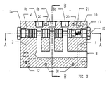
- a parallel circuit hydraulic drive system for a vehicle such as a three wheel drive forklift truck which hydraulic drive system incorporates the fluid control valve of the present invention indicated generally by reference numeral 1.
- the hydraulic drive system A includes a prime mover 6, and a high-pressure transmission pump 5 coupled to the prime mover 6 to provide the hydraulic drive for the hydraulic drive system A. Also included in the hydraulic drive system A is the fluid control valve 1 of the present invention as well as a charge pump 4, fluid supply and return lines 8 and 9, motors 7, auxiliary fluid lines 11, 12, 13, a source of fluid 19 and a reservoir (or sump) 14. Construction hole plugs 18 provided on the periphery of the manifold block 1 a block access to fluid lines 11, 12 and 13. It is to be understood that fluid lines 8 and 9, and auxiliary fluid lines 11, 12, 13 are not connected and as such are separate fluid lines.
- the high-pressure transmission pump 5 is operable in forward or reverse bias thereby providing high-pressure fluid supply to either line 8 or line 9 while the other line 9 or 8 acts as a low pressure fluid return line. It is to be understood that high-pressure includes any pressure up to but not limited to 450 Bar.
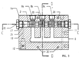
- the fluid control valve 1 comprises a manifold block 1a having fluid lines 8, 8a, 8b, 8c, auxiliary fluid lines 11, 12, 13, a flow divider/combiner spool 2 received within a spool chamber (not shown) and a control compression spring 10. Additionally and conveniently, the fluid control valve 1 comprises a solenoid operated, 3-way, selector valve 3, as shown in Figure 4.
- Auxiliary fluid line 11 connects the flow divider/combiner spool 2 to the reservoir 14, as well as linking the selector valve 3 to the reservoir 14.
- Auxiliary fluid line 12 provides a pressure connection between the selector valve 3 and the charge pump 4 whereas auxiliary fluid line 13 connects the flow divider/combiner spool 2 to the selector valve 3.
- the fluid passing through auxiliary fluid lines 11, 12 and 13 is at a lower pressure than the fluid in supply line 8.
- the flow divider/ combiner spool 2 comprises a high pressure shuttle type spool.
- the position of the spool 2 in the spool chamber 21 is selectable by an operator.
- the flow divider/combiner spool 2 is biased in the first position by the force of the compression spring 10.
- Auxiliary fluid lines 11 and 13 are connected while blocking any connection between auxiliary fluid lines 12 and 13. This enables the compression spring 10 to control the position of the flow divider/combiner spool 2 since auxiliary fluid line 13 has a direct connection to the reservoir 14.
- the manifold block 1a of the fluid control valve is mounted on a vehicle chassis or axle through mounting holes 20.
- the flow divider/combiner spool 2 extends along the length of the manifold block 1a and is capped at either end with a sealing member 17 and access plug 16.
- the fluid line 8 is divided into fluid lines 8a, 8b and 8c which intersect the flow divider/combiner spool 2.
- the fluid control valve 1 provides divided flow from transmission pump 5 to motors 7 via fluid lines 8a, 8b and 8c or combined flow from motors 7 to transmission pump 5 via fluid lines 8a, 8b or 8c.
- Divided flow to the motors 7 is provided when the transmission pump 5 is operating in forward bias and fluid line 8 is a high-pressure fluid supply line, with fluid line 9 acting as a low-pressure fluid return line.
- combined flow from the motors 7 is provided when the transmission pump 5 is operating in reverse bias and fluid line 8 is a low-pressure fluid return line, with fluid line 9 acting as a high-pressure fluid supply line.
- the fluid line 9 is divided into fluid lines 9a, 9b and 9c which supply fluid to the motors 7. Fluid flow through the flow divider/combiner spool 2 to or from the motors can either be unrestricted or controlled (metered) depending on whether or not the selector valve 3 is activated.
- the spool 2 includes a plurality of full flow sections 2a and a plurality of discrete (non-continuous) controlled flow members (grooves) 2b.
- the full flow sections 2a are aligned with the fluid lines 8a, 8b and 8c when the selector valve 3 is not activated, whereas the controlled flow members 2b are aligned with the fluid lines 8a, 8b and 8c when the selector valve 3 is activated.
- the flow divider/combiner spool 2 has cylindrical metering and lubrication grooves 15 on the outer surface of flow members 2b which provide a restricted flow path between the pump and the motors when the selector valve 3 is activated.
- Figure 8 shows the controlled flow path from fluid line 8a, 8b or 8c through the spool chamber 21 to a motor 7 through the metering and lubrication grooves 15 on the outer surface of controlled flow members 2b.
- a controlled flow path 22, formed by and between the grooves 15 and the walls of the spool chamber 21 provide a controlled flow path from fluid line 8a, 8b or 8c to a motor 7 and vice versa.
- the direction of fluid flow along flow path 22 is illustrated by arrows in Figure 8.
- the fluid control valve 1 will now be described in use.
- the compression spring 10 forces the high pressure flow divider/combiner spool 2 to remain biased in the first position, thereby enabling full free flow of hydraulic fluid between the transmission pump 5 and the wheel motors 7.
- the selector valve 3 When driving on uneven ground, in conditions where wheel slip is likely, the selector valve 3 is activated by the driver causing a charge pressure from the charge pump 4 to overcome the compression spring force and move the divider/combiner spool 2 in the opposite direction. This results in controlled flow to or from the wheel motors 7. Controlled flow is only provided after the selector valve 3 is activated. By restricting the flow of fluid between the pump and the wheel motors 7, equal fluid pressure and flow is delivered to each wheel, causing them to rotate in a synchronized fashion when traction control is required thereby allowing vehicle motion to be resumed. The selector valve 3 is only required to initiate movement of the spool 2 to the second position (controlled flow).
- the action of the high transmission pump fluid flow passing along the fluid control members 15 causes the spool 2 to remain in position.
- the transmission pump fluid flow is reduced (caused by a reflex response by the driver to reduce engine throttle when traction is regained)
- the spool 2 will be moved from the second position to the first position under action of the biasing means (compression spring).
Applications Claiming Priority (1)
| Application Number | Priority Date | Filing Date | Title |
|---|---|---|---|
| IE20040688A IES20040688A2 (en) | 2004-10-12 | 2004-10-12 | A fluid control valve |
Publications (1)
| Publication Number | Publication Date |
|---|---|
| EP1647720A1 true EP1647720A1 (de) | 2006-04-19 |
Family
ID=35456017
Family Applications (1)
| Application Number | Title | Priority Date | Filing Date |
|---|---|---|---|
| EP20050394029 Withdrawn EP1647720A1 (de) | 2004-10-12 | 2005-10-11 | Schieberventil |
Country Status (5)
| Country | Link |
|---|---|
| US (1) | US20060076067A1 (de) |
| EP (1) | EP1647720A1 (de) |
| AU (1) | AU2005220263A1 (de) |
| CA (1) | CA2523114A1 (de) |
| IE (1) | IES20040688A2 (de) |
Cited By (1)
| Publication number | Priority date | Publication date | Assignee | Title |
|---|---|---|---|---|
| WO2008058739A1 (de) * | 2006-11-15 | 2008-05-22 | Robert Bosch Gmb | Hydrostatischer fahrantrieb mit zwei hydromotoren |
Families Citing this family (5)
| Publication number | Priority date | Publication date | Assignee | Title |
|---|---|---|---|---|
| KR101216828B1 (ko) * | 2002-12-30 | 2013-01-04 | 더 리전트 오브 더 유니버시티 오브 캘리포니아 | 병원균 검출과 분석을 위한 방법과 기구 |
| US7377353B2 (en) * | 2004-07-29 | 2008-05-27 | Sauer-Danfoss Inc. | Four wheel traction control valve system |
| WO2012006303A1 (en) | 2010-07-06 | 2012-01-12 | Jlg Industries, Inc. | Selectable flow divider drive system |
| CN104806597B (zh) * | 2015-04-16 | 2018-11-06 | 浙江纺织服装职业技术学院 | 一种控制冷轧管机液压式双回双送的换向转阀 |
| CN109469660B (zh) * | 2018-11-30 | 2020-03-06 | 广东轻工职业技术学院 | 一种双重阀芯控制同步阀 |
Citations (4)
| Publication number | Priority date | Publication date | Assignee | Title |
|---|---|---|---|---|
| US5647211A (en) | 1996-03-06 | 1997-07-15 | Fluidrive, Inc. | Fluid control valve |
| US6364280B1 (en) * | 2000-06-02 | 2002-04-02 | Damir Anton Fox | Adjustable slow shift control unit |
| US20030034076A1 (en) * | 2001-08-20 | 2003-02-20 | Hyun-Suk Kim | Spool valve for controlling oil pressure |
| US20040261696A1 (en) * | 2003-06-27 | 2004-12-30 | Ackerman Bryan L. | Method and apparatus for application of a material to a substrate |
Family Cites Families (11)
| Publication number | Priority date | Publication date | Assignee | Title |
|---|---|---|---|---|
| US2136510A (en) * | 1936-09-23 | 1938-11-15 | Gustav B Jensen | Automobile seat inflation device |
| US2655940A (en) * | 1950-01-09 | 1953-10-20 | North American Aviation Inc | Time-modulated two-stage hydraulic valve |
| US3508562A (en) * | 1968-05-01 | 1970-04-28 | Ford Motor Co | Speed responsive fluid pressure controller |
| US3590873A (en) * | 1968-07-26 | 1971-07-06 | Ltv Electrosystems Inc | Valve mechanism |
| US3578007A (en) * | 1969-12-10 | 1971-05-11 | Caterpillar Tractor Co | Delayed governor cutoff valve |
| US3763891A (en) * | 1972-01-13 | 1973-10-09 | M Stiltner | Control valve |
| US3973583A (en) * | 1973-05-21 | 1976-08-10 | Sorenson Gerald T | Fluid control system |
| US3971542A (en) * | 1974-07-05 | 1976-07-27 | The Lee Company | Fluid valve and valve system |
| US4099588A (en) * | 1976-09-01 | 1978-07-11 | Caterpillar Tractor Co. | Responsive pilot-operated control valve for front wheel drive |
| DE2827137A1 (de) * | 1978-06-21 | 1980-01-10 | Lincoln Helios Gmbh | Mehrfachkupplung fuer schmiersysteme |
| JPH0440053Y2 (de) * | 1984-12-18 | 1992-09-18 |
-
2004
- 2004-10-12 IE IE20040688A patent/IES20040688A2/en not_active IP Right Cessation
-
2005
- 2005-10-10 AU AU2005220263A patent/AU2005220263A1/en not_active Abandoned
- 2005-10-11 US US11/248,930 patent/US20060076067A1/en not_active Abandoned
- 2005-10-11 EP EP20050394029 patent/EP1647720A1/de not_active Withdrawn
- 2005-10-12 CA CA 2523114 patent/CA2523114A1/en not_active Abandoned
Patent Citations (4)
| Publication number | Priority date | Publication date | Assignee | Title |
|---|---|---|---|---|
| US5647211A (en) | 1996-03-06 | 1997-07-15 | Fluidrive, Inc. | Fluid control valve |
| US6364280B1 (en) * | 2000-06-02 | 2002-04-02 | Damir Anton Fox | Adjustable slow shift control unit |
| US20030034076A1 (en) * | 2001-08-20 | 2003-02-20 | Hyun-Suk Kim | Spool valve for controlling oil pressure |
| US20040261696A1 (en) * | 2003-06-27 | 2004-12-30 | Ackerman Bryan L. | Method and apparatus for application of a material to a substrate |
Cited By (2)
| Publication number | Priority date | Publication date | Assignee | Title |
|---|---|---|---|---|
| WO2008058739A1 (de) * | 2006-11-15 | 2008-05-22 | Robert Bosch Gmb | Hydrostatischer fahrantrieb mit zwei hydromotoren |
| US8356479B2 (en) | 2006-11-15 | 2013-01-22 | Robert Bosch Gmbh | Hydrostatic travel drive having two hydraulic motors |
Also Published As
| Publication number | Publication date |
|---|---|
| AU2005220263A1 (en) | 2006-04-27 |
| US20060076067A1 (en) | 2006-04-13 |
| IES20040688A2 (en) | 2006-04-19 |
| CA2523114A1 (en) | 2006-04-12 |
Similar Documents
| Publication | Publication Date | Title |
|---|---|---|
| US6408972B1 (en) | Electronic traction control system | |
| US6189641B1 (en) | Four-wheel hydraulic drive system for working vehicle | |
| US6971232B2 (en) | Hydraulic drive system and improved control valve assembly therefor | |
| US6394238B1 (en) | Regenerative suspension for an off-road vehicle | |
| EP1647720A1 (de) | Schieberventil | |
| EP1188587B1 (de) | Regenerativaufhängung für ein Geländefahrzeug | |
| US8900086B2 (en) | Hydraulic vehicle clutch system, drivetrain for a vehicle including same, and method | |
| US20080128189A1 (en) | Systems and methods for controlling slip of vehicle drive members | |
| US5647211A (en) | Fluid control valve | |
| CN1757553A (zh) | 集成扭矩和侧滚控制系统 | |
| EP3774431B1 (de) | Hydraulischer antriebsstrang für ein nutzfahrzeug | |
| CN107061687A (zh) | 控制限滑式差速器的方法 | |
| JP6663197B2 (ja) | サスペンション装置 | |
| US4766727A (en) | Fluid control valve | |
| CA1123707A (en) | Auxiliary drive system with neutral | |
| JP2005155686A5 (de) | ||
| JP2005155686A (ja) | 車軸駆動装置及びそれを備える四輪駆動車両 | |
| US5720360A (en) | Limited slip differential hydraulic drive system | |
| JPH1044803A (ja) | 油圧式四駆車両 | |
| IES84323Y1 (en) | A fluid control valve | |
| IE20040688U1 (en) | A fluid control valve | |
| GB2362700A (en) | Anti backspin vehicle propulsion arrangement | |
| CN113864261B (zh) | 液压系统和作业车辆 | |
| JPH0567464B2 (de) | ||
| CN110701128A (zh) | 一种控制阀及其工作方法 |
Legal Events
| Date | Code | Title | Description |
|---|---|---|---|
| PUAI | Public reference made under article 153(3) epc to a published international application that has entered the european phase |
Free format text: ORIGINAL CODE: 0009012 |
|
| AK | Designated contracting states |
Kind code of ref document: A1 Designated state(s): AT BE BG CH CY CZ DE DK EE ES FI FR GB GR HU IE IS IT LI LT LU LV MC NL PL PT RO SE SI SK TR |
|
| AX | Request for extension of the european patent |
Extension state: AL BA HR MK YU |
|
| 17P | Request for examination filed |
Effective date: 20061019 |
|
| AKX | Designation fees paid |
Designated state(s): GB IE |
|
| REG | Reference to a national code |
Ref country code: DE Ref legal event code: 8566 |
|
| 17Q | First examination report despatched |
Effective date: 20071122 |
|
| STAA | Information on the status of an ep patent application or granted ep patent |
Free format text: STATUS: THE APPLICATION IS DEEMED TO BE WITHDRAWN |
|
| 18D | Application deemed to be withdrawn |
Effective date: 20080403 |