EP1647701A1 - Air cleaner - Google Patents
Air cleaner Download PDFInfo
- Publication number
- EP1647701A1 EP1647701A1 EP05022244A EP05022244A EP1647701A1 EP 1647701 A1 EP1647701 A1 EP 1647701A1 EP 05022244 A EP05022244 A EP 05022244A EP 05022244 A EP05022244 A EP 05022244A EP 1647701 A1 EP1647701 A1 EP 1647701A1
- Authority
- EP
- European Patent Office
- Prior art keywords
- sealing frame
- casing body
- outer peripheral
- filter
- fitting part
- Prior art date
- Legal status (The legal status is an assumption and is not a legal conclusion. Google has not performed a legal analysis and makes no representation as to the accuracy of the status listed.)
- Granted
Links
Images


Classifications
-
- B—PERFORMING OPERATIONS; TRANSPORTING
- B01—PHYSICAL OR CHEMICAL PROCESSES OR APPARATUS IN GENERAL
- B01D—SEPARATION
- B01D46/00—Filters or filtering processes specially modified for separating dispersed particles from gases or vapours
- B01D46/10—Particle separators, e.g. dust precipitators, using filter plates, sheets or pads having plane surfaces
-
- B—PERFORMING OPERATIONS; TRANSPORTING
- B01—PHYSICAL OR CHEMICAL PROCESSES OR APPARATUS IN GENERAL
- B01D—SEPARATION
- B01D46/00—Filters or filtering processes specially modified for separating dispersed particles from gases or vapours
-
- B—PERFORMING OPERATIONS; TRANSPORTING
- B01—PHYSICAL OR CHEMICAL PROCESSES OR APPARATUS IN GENERAL
- B01D—SEPARATION
- B01D46/00—Filters or filtering processes specially modified for separating dispersed particles from gases or vapours
- B01D46/0039—Filters or filtering processes specially modified for separating dispersed particles from gases or vapours with flow guiding by feed or discharge devices
- B01D46/0047—Filters or filtering processes specially modified for separating dispersed particles from gases or vapours with flow guiding by feed or discharge devices for discharging the filtered gas
- B01D46/0049—Filters or filtering processes specially modified for separating dispersed particles from gases or vapours with flow guiding by feed or discharge devices for discharging the filtered gas containing fixed gas displacement elements or cores
-
- F—MECHANICAL ENGINEERING; LIGHTING; HEATING; WEAPONS; BLASTING
- F02—COMBUSTION ENGINES; HOT-GAS OR COMBUSTION-PRODUCT ENGINE PLANTS
- F02M—SUPPLYING COMBUSTION ENGINES IN GENERAL WITH COMBUSTIBLE MIXTURES OR CONSTITUENTS THEREOF
- F02M35/00—Combustion-air cleaners, air intakes, intake silencers, or induction systems specially adapted for, or arranged on, internal-combustion engines
- F02M35/02—Air cleaners
- F02M35/024—Air cleaners using filters, e.g. moistened
-
- B—PERFORMING OPERATIONS; TRANSPORTING
- B01—PHYSICAL OR CHEMICAL PROCESSES OR APPARATUS IN GENERAL
- B01D—SEPARATION
- B01D2271/00—Sealings for filters specially adapted for separating dispersed particles from gases or vapours
- B01D2271/02—Gaskets, sealings
- B01D2271/022—Axial sealings
-
- B—PERFORMING OPERATIONS; TRANSPORTING
- B01—PHYSICAL OR CHEMICAL PROCESSES OR APPARATUS IN GENERAL
- B01D—SEPARATION
- B01D2279/00—Filters adapted for separating dispersed particles from gases or vapours specially modified for specific uses
- B01D2279/60—Filters adapted for separating dispersed particles from gases or vapours specially modified for specific uses for the intake of internal combustion engines or turbines
Definitions
- the present invention relates to an improvement in an air cleaner for use on a multi-purpose engine.
- An air cleaner is a part for filtering air containing dust and supplying filtered clean air to an engine.
- a filter for filtering air is detachably attached to a casing forming a body of the air cleaner.
- JP-A-10-252585 proposes an air cleaner with a sealing frame of a elastic material interposed between a casing and a filter, leaving no gap therebetween. The proposed air cleaner arrangement will now be described with reference to Fig. 6 hereof.
- the conventional air cleaner 100 is comprised of a casing 102 with a communication hole (101) communicating with a carburetor, not shown, a sealing frame 103 made of a elastic material and fitted in the casing 102, a filter 104 engaged with the sealing frame 103, a backup frame 105 for supporting the filter 104, and a cover 106 for securing the backup frame 105.
- the backup frame 105 presses the sealing frame 103 against the casing 102 to thereby prevent dust from passing between the sealing frame 103 and the casing 102.
- the conventional air cleaner has a drawback in that the casing 102 is likely to have dimension errors that lead to distortion in a bearing surface 108 of the sealing frame 103, Similarly, the backup frame 105 and the cover 106 are likely to have dimension errors that result in a shortage in the pressing force of the backup frame 105 against the sealing frame 103. Such distortion and pressing force shortage will give rise to a gap 107 between the casing 102 and the sealing frame 103, thus deteriorating a sealing effect between them. Consequently, there is a demand for an improvement in a sealing effect between the sealing frame and the casing.
- an air cleaner which comprises: a casing body having an opening communicating with a carburetor; a sealing frame designed to be engaged in a fitting part of the casing body; a filter disposed internally of the sealing frame; and a cover for covering the filter and the sealing frame, wherein the sealing frame has a front surface, a rear surface and an outer peripheral surface, the fitting part has an inner wall surface held in contact with an outer peripheral surface of the sealing frame, and a bearing surface held in contact with the rear surface of the sealing frame, and the sealing frame has a groove extending along the outer peripheral surface and opening on the front surface.
- the sealing frame is provided with the groove extending along its outer peripheral surface and opening on its front surface so that the outer peripheral surface of the sealing frame can easily bends toward the filter, the outer peripheral surface of the sealing frame contacts the inner wall surface of the casing body and, while bending, moves on the inner wall surface of the casing body.
- the rear surface of the sealing frame in pressed contact with the bearing surface of the fitting part. Consequently, increased sealing is established between the casing body and the sealing frame and the releasable attachment capability of the sealing frame is increased.
- Placing the filter in tight contact with the inside of the sealing frame to make them unitarily coupled not only produces an improved sealing effect between the casing body and the filter but also facilitates releasable attachment of the filter.
- the outer peripheral surface of the sealing frame is tapered such that the rear surface of the sealing frame has a diameter smaller than a diameter of an inlet part of the fitting part and the front surface of the sealing frame has a diameter larger than a diameter of the inlet part of the fitting part.
- the sealing frame it becomes possible for the sealing frame to easily engage in the casing body.
- the outer peripheral part defined by the groove easily deforms elastically as deep as the diameter of the inlet part of the fitting part to thereby perform a spring function, thus providing an improved sealing effect.
- the engine 11 includes a crankcase 12, a cylinder block 13 being in one piece with the crankcase 12, a cylinder head 14 mounted to the cylinder block 13, a carburetor 15 disposed sidewardly of the cylinder head 14 for mixing fuel with air at a predetermined ratio and supplying the mixture to the engine, an air cleaner 16 mounted to the carburetor 15 for filtering dust and dirt out of air drawn into the carburetor, and a fuel tank 18 for supplying fuel through a fuel pipe 17 to the carburetor 15.
- reference numeral 19 designates a power output shaft projecting downwardly.
- Reference numeral 21 denotes a recoil starter.
- a starter grip 22 is mounted to the recoil starter 21 via a rope, not shown.
- Reference numeral 23 denotes a filler cap while 24 denotes a fuel cock.
- the air cleaner 16 is comprised of a casing body 26 having an opening 25 communicating with the carburetor 15, a sealing frame 27 fitted within the casing body 26, a filter 28 disposed inside the sealing frame 27, and a cover 31 for protecting the filter. 28.
- the sealing frame 27 is made of a elastic material such as rubber.
- the filter 28 is placed in tight contact with an inner peripheral surface of the sealing frame 27 and remains unitarily with the sealing frame 27.
- the unitarily joined sealing frame 27 and filter 28 are fitted in a fitting part 39 of the casing body 26 and is enclosed by a cover 31.
- an inner peripheral wall 32 extends all around for holding the sealing frame 27 and filter 28 against the casing body 26.
- a hinge shaft 33 Disposed below the casing body 26 is a hinge shaft 33 with which a hinge bracket part 34 provided on the cover 31 rotationally engages.
- the cover 31 is supported rotatably with respect to the casing body 26 via the hinge shaft 33 and the hinge bracket 34.
- a to-be-engaged part 35 is provided above the casing body 26 while an engaging part 36 is provided above the cover 31.
- the engaging part 36 is designed to releasably engage with the to-be-engaged part 35.
- the cover 31 is separably coupled with the casing body 26. Separation of the cover 31 from the casing body 26 makes it possible to take out the filter 28 for the sake of maintenance.
- the cover 31 has an air intake opening 37. Outside air is introduced inside through the air intake opening 37. Outside air taken in through the air intake opening 37 is directed to the filter 28 through a communication hole 38 formed in a part of the inner peripheral wall 32.
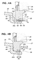
- FIG. 4A and 4B showing a relationship between the casing body 26 and the sealing frame 27.
- the sealing frame has a plurality of grooves 47 formed on a front surface 42 along a circumference thereof.
- the grooves 47 are tapered a predetermined angle ⁇ with respect to a direction in which the sealing frame 27 is inserted into the casing body 26.
- the grooves 47 do not extend in all directions on an entire periphery of the front surface 42 of the sealing frame 27 but are spaced from each other such that they have desired lengths. Between the grooves 47 there are formed ribs for rigidity control.
- the grooves 47 are positioned radially outwardly of a distal end 32a of the inner peripheral surface 32.
- the sealing frame 27 has a rear surface 43 and an outer peripheral part 44.
- the casing body 26 includes the fitting part 39 which has an inner wall surface 46 in contact with an outer peripheral surface 44a of the outer peripheral part 44 and a bearing surface 45 in contact with a peripheral edge 43a of the rear surface 43 of the sealing frame 27.
- the sealing frame 27 has an outer peripheral surface 44a which is tapered as at 62 such that an outer periphery of the rear surface 43 of the sealing frame 27 becomes a length P smaller than an inlet part 61 of the fitting part 39 while an outer periphery of the front surface 42 of the sealing frame 27 becomes a length Q larger than the inlet 61 of the fitting part 39.
- the rear surface 43 of the sealing frame 27 has a diameter smaller than a diameter of the inlet part 61 of the fitting part 39 while the front surface 42 of the sealing frame 27 has a diameter larger than a diameter of the inlet part 61 of the fitting part 39.
- the sealing frame 27 and the filter 28 are engaged in the fitting part 39 of the casing body 26.
- the rear surface 43 of the casing body 26 comes into abutting engagement with the bearing surface 45 while the outer peripheral part 44 of the sealing frame 27 deforms in the direction of the grooves 47. Since the outer peripheral surface 44a of the sealing frame 27 is tapered as at 62, the sealing frame 27 is held against the casing body 26 with increased tightness.
- the distal end 32a of the inner peripheral wall 32 of the cover 31 (see Fig. 2) is brought into pressing contact with the front surface 42 of the sealing frame 27 while the rear surface 43 of the sealing frame 27 unified with the filter 28 is brought into pressing contact with the bearing surface 45 of the casing body 26.
- the outer peripheral surface 44a of the sealing frame 27 is placed in tight contact with the inner wall surface 46 of the casing body 26. Because the sealing frame 27 is elastic and has the grooves 47 formed in the front surface 42 thereof and opening along the outer peripheral part 44, the outer peripheral part 44 bends inwardly to bring the outer peripheral surface 44a into tight contact with the inner wall surface 46.
- the casing body 26 has a ridge 48 extending around the entire periphery of the bearing surface 45 thereof.
- the distal end 32a of the inner peripheral wall 32 is positioned in opposed relation to the ridge 48 which in turn is placed in confronting relation to the peripheral edge 43a at the rear surface 43 of the sealing frame 27.
- the ridge 48 bites into the elastic sealing frame 27 to provide an increased sealing effect.
- the filter 28, unitarily coupled with the sealing frame 27, is retained by the casing body 26.
- FIG. 5A and 5B illustrating an example sealing frame 32 of this invention and a sealing frame 27B as a comparison example, respectively.
- the distal end 32a of the inner peripheral wall 32 presses and bites into the front surface 42 of the elastic sealing frame 27 to thereby fix the sealing frame 27 and the filter 28 unitarily coupled therewith against the casing body 26.
- the groove 47 formed in the front surface 42 of the sealing frame 27 have a depth D.
- the outer peripheral part 44 of the sealing frame 27 has a thickness T. That is, the grooves 27 are at a position spaced a distance T from the outer peripheral surface 44a. As a result, the outer peripheral part 44 can easily deform inwardly.
- the front surface 42 of the sealing frame 27 is thus notched to provide the grooves 47 of the depth D.
- the grooves 47 When the sealing frame 27 is engaged in the fitting part 39 of the casing body 26, the grooves 47 have a width S.
- the grooves 47 have an angle of inclination ⁇ (Fig. 4A) a degree of inclination of which angle corresponds to an amount in which the outer peripheral part 44 can bend.
- the outer peripheral part 44 of the sealing frame 27 takes the form of a cantilever having a length D and a thickness T and functions as a leaf spring.
- the outer peripheral part 44 of length D and thickness T bends to cause the outer peripheral surface 44a of the outer peripheral part 44 to tightly contact the inner wall surface 46.
- the outer peripheral surface 44a of the sealing frame 27 is tapered toward a direction of engagement.
- the ridge 48 is provided in opposed relation to the distal end 32a of the inner peripheral wall 32.
- the ridge 48 is positioned closer to the filter 28 than the grooves 47.
- the cover 31 is mounted to the casing body 26, the ridge 48 bites into the sealing frame 27 as deep as its bulge to thereby prevent leakage of dusty air to downstream of an intake air stream.
- the sealing frame 27 can be surely engaged in the fitting part 39 because the outer peripheral part 44 deforms to kill the dimension errors, bringing the sealing frame 27 into tight contact with the casing body 26.
- FIG. 5B showing a sealing frame 27B as a comparative example, without grooves formed in a front surface 42B thereof.
- the sealing frame 27B of the comparison example has no grooves.
- the sealing frame 27B does not deform sufficiently. Consequently, continued pressing of the front surface 42B of the sealing frame 27B with the distal end 32a of the inner peripheral wall 32B will not end up engaging the sealing frame 27B in the fitting part 39B sufficiently, thus failing to place the rear surface 43B of the sealing frame 27B in tight contact with the bearing surface 45B and to place the outer peripheral surface 44B of the sealing frame 27B in tight contact with the inner wall surface 46B of the casing body 26B
- the sealing frame 27 of the present embodiment has the grooves 42 extending along the outer peripheral part 44 and opening on the front surface 42, upon engagement of he sealing frame 27 in the casing body 26, the outer peripheral part 44 bends and moves on the inner wall surface 46 of the casing body 26. Consequently, the outer peripheral surface 44a of the sealing frame 27 is placed in tight contact with the inner wall surface 46 of the casing body 26 while the rear surface 43 of the sealing frame 27 is placed in tight contact with the bearing surface 45 of the fitting part 43.
- the air cleaner of the present invention has been described as it is applied to a general-purpose engine, it may also be applied to a two-wheeled vehicle, as well as to an automobiles.
- An air cleaner including a casing body (26) and a sealing frame (27) is disclosed.
- the casing body has a fitting part (39) for allowing engagement of the sealing frame therein.
- a filter (28) is mounted inside the sealing frame in a tightly contacted relation with the latter.
- the sealing frame has a groove (47) extending along its outer peripheral surface (44a) and opening on its front surface (42).
Landscapes
- Engineering & Computer Science (AREA)
- Chemical & Material Sciences (AREA)
- Chemical Kinetics & Catalysis (AREA)
- Combustion & Propulsion (AREA)
- Mechanical Engineering (AREA)
- General Engineering & Computer Science (AREA)
- Filtering Of Dispersed Particles In Gases (AREA)
Abstract
Description
- The present invention relates to an improvement in an air cleaner for use on a multi-purpose engine.
- An air cleaner is a part for filtering air containing dust and supplying filtered clean air to an engine. For the purpose of maintenance, a filter for filtering air is detachably attached to a casing forming a body of the air cleaner. When the filter is attached to the casing with a gap left between the filter and the casing, air containing dust is likely to enter through the gap into a carburetor on an engine side. To this end, JP-A-10-252585, for example, proposes an air cleaner with a sealing frame of a elastic material interposed between a casing and a filter, leaving no gap therebetween. The proposed air cleaner arrangement will now be described with reference to Fig. 6 hereof.
- As shown in Fig. 6, the
conventional air cleaner 100 is comprised of acasing 102 with a communication hole (101) communicating with a carburetor, not shown, a sealingframe 103 made of a elastic material and fitted in thecasing 102, afilter 104 engaged with the sealingframe 103, abackup frame 105 for supporting thefilter 104, and acover 106 for securing thebackup frame 105. Thebackup frame 105 presses the sealingframe 103 against thecasing 102 to thereby prevent dust from passing between the sealingframe 103 and thecasing 102. - However, the conventional air cleaner has a drawback in that the
casing 102 is likely to have dimension errors that lead to distortion in abearing surface 108 of the sealingframe 103, Similarly, thebackup frame 105 and thecover 106 are likely to have dimension errors that result in a shortage in the pressing force of thebackup frame 105 against the sealingframe 103. Such distortion and pressing force shortage will give rise to agap 107 between thecasing 102 and the sealingframe 103, thus deteriorating a sealing effect between them. Consequently, there is a demand for an improvement in a sealing effect between the sealing frame and the casing. - According to an aspect of the present invention, there is provided an air cleaner which comprises: a casing body having an opening communicating with a carburetor; a sealing frame designed to be engaged in a fitting part of the casing body; a filter disposed internally of the sealing frame; and a cover for covering the filter and the sealing frame, wherein the sealing frame has a front surface, a rear surface and an outer peripheral surface, the fitting part has an inner wall surface held in contact with an outer peripheral surface of the sealing frame, and a bearing surface held in contact with the rear surface of the sealing frame, and the sealing frame has a groove extending along the outer peripheral surface and opening on the front surface.
- Since the sealing frame is provided with the groove extending along its outer peripheral surface and opening on its front surface so that the outer peripheral surface of the sealing frame can easily bends toward the filter, the outer peripheral surface of the sealing frame contacts the inner wall surface of the casing body and, while bending, moves on the inner wall surface of the casing body. As a result, it becomes possible to place the rear surface of the sealing frame in pressed contact with the bearing surface of the fitting part. Consequently, increased sealing is established between the casing body and the sealing frame and the releasable attachment capability of the sealing frame is increased. Placing the filter in tight contact with the inside of the sealing frame to make them unitarily coupled not only produces an improved sealing effect between the casing body and the filter but also facilitates releasable attachment of the filter.
- Further, because the outer peripheral part defined by the groove provided in the sealing frame elastically deforms, a releasable attachment operation for the sealing frame becomes easy.
- Preferably, the outer peripheral surface of the sealing frame is tapered such that the rear surface of the sealing frame has a diameter smaller than a diameter of an inlet part of the fitting part and the front surface of the sealing frame has a diameter larger than a diameter of the inlet part of the fitting part. With this arrangement, it becomes possible for the sealing frame to easily engage in the casing body. Further, the outer peripheral part defined by the groove easily deforms elastically as deep as the diameter of the inlet part of the fitting part to thereby perform a spring function, thus providing an improved sealing effect.
- A preferred embodiment of the present invention will be described in detail below, by way of example only, with reference to the accompanying drawings, in which:
- Fig. 1 is a side view illustrating a multi-purpose engine employing an air cleaner according to the present invention;
- Fig. 2 is a cross-sectional view taken along line 2 - 2 of Fig. 1;
- Fig. 3 is a cross-sectional view taken along line 3 - 3 of Fig. 1;
- Fig. 4A and Fig. 4B are partially enlarged sectional view showing a relationship between a casing body and a sealing frame shown in Fig. 2;
- Fig. 5A and Fig. 5B respectively illustrate in partially enlarged section a relationship between the casing body and the sealing frame according to an example or embodiment of the present invention and a relationship between a casing body and a sealing frame according to a comparison example; and
- Fig. 6 is a cross-sectional view showing a conventional air cleaner.
- Reference is made initially to Fig. 1 showing a
multi-purpose engine 11 employing an air cleaner according to the present invention. As shown, theengine 11 includes acrankcase 12, acylinder block 13 being in one piece with thecrankcase 12, acylinder head 14 mounted to thecylinder block 13, acarburetor 15 disposed sidewardly of thecylinder head 14 for mixing fuel with air at a predetermined ratio and supplying the mixture to the engine, anair cleaner 16 mounted to thecarburetor 15 for filtering dust and dirt out of air drawn into the carburetor, and afuel tank 18 for supplying fuel through afuel pipe 17 to thecarburetor 15. - In the Figure,
reference numeral 19 designates a power output shaft projecting downwardly.Reference numeral 21 denotes a recoil starter. Astarter grip 22 is mounted to therecoil starter 21 via a rope, not shown.Reference numeral 23 denotes a filler cap while 24 denotes a fuel cock. - Turning now to Fig. 2, the
air cleaner 16 is comprised of acasing body 26 having an opening 25 communicating with thecarburetor 15, a sealingframe 27 fitted within thecasing body 26, afilter 28 disposed inside the sealingframe 27, and acover 31 for protecting the filter. 28. The sealingframe 27 is made of a elastic material such as rubber. - The
filter 28 is placed in tight contact with an inner peripheral surface of the sealingframe 27 and remains unitarily with the sealingframe 27. The unitarily joined sealingframe 27 andfilter 28 are fitted in afitting part 39 of thecasing body 26 and is enclosed by acover 31. - Inside the
cover 31, an innerperipheral wall 32 extends all around for holding the sealingframe 27 and filter 28 against thecasing body 26. By pressing the sealingframe 27 against thecasing body 26 with the innerperipheral wall 32, the sealingframe 27 is placed in tight contact with thecasing body 26. - Disposed below the
casing body 26 is ahinge shaft 33 with which ahinge bracket part 34 provided on thecover 31 rotationally engages. Thus, thecover 31 is supported rotatably with respect to thecasing body 26 via thehinge shaft 33 and thehinge bracket 34. - A to-
be-engaged part 35 is provided above thecasing body 26 while anengaging part 36 is provided above thecover 31. Theengaging part 36 is designed to releasably engage with the to-be-engaged part 35. - In this way, the
cover 31 is separably coupled with thecasing body 26. Separation of thecover 31 from thecasing body 26 makes it possible to take out thefilter 28 for the sake of maintenance. - Since the
filter 28 and the sealingframe 27 are held tight against each other unitarily, there is no fear that dusty air will leak from between thefilter 28 and the sealingframe 27. - Referring now to Fig. 3, the
cover 31 has an air intake opening 37. Outside air is introduced inside through the air intake opening 37. Outside air taken in through theair intake opening 37 is directed to thefilter 28 through acommunication hole 38 formed in a part of the innerperipheral wall 32. - Next, reference is made to Figs. 4A and 4B showing a relationship between the
casing body 26 and the sealingframe 27. - As shown in Fig. 4A, the sealing frame has a plurality of
grooves 47 formed on afront surface 42 along a circumference thereof. Thegrooves 47 are tapered a predetermined angle θ with respect to a direction in which the sealingframe 27 is inserted into thecasing body 26. Thegrooves 47 do not extend in all directions on an entire periphery of thefront surface 42 of the sealingframe 27 but are spaced from each other such that they have desired lengths. Between thegrooves 47 there are formed ribs for rigidity control. Thegrooves 47 are positioned radially outwardly of adistal end 32a of the innerperipheral surface 32. - Apart from the
front surface 42, the sealingframe 27 has arear surface 43 and an outerperipheral part 44. For allowing fitting of the sealingframe 27 in thecasing body 26, thecasing body 26 includes thefitting part 39 which has aninner wall surface 46 in contact with an outerperipheral surface 44a of the outerperipheral part 44 and abearing surface 45 in contact with aperipheral edge 43a of therear surface 43 of the sealingframe 27. - The sealing
frame 27 has an outerperipheral surface 44a which is tapered as at 62 such that an outer periphery of therear surface 43 of thesealing frame 27 becomes a length P smaller than aninlet part 61 of thefitting part 39 while an outer periphery of thefront surface 42 of the sealingframe 27 becomes a length Q larger than theinlet 61 of thefitting part 39. Namely, therear surface 43 of the sealingframe 27 has a diameter smaller than a diameter of theinlet part 61 of thefitting part 39 while thefront surface 42 of the sealingframe 27 has a diameter larger than a diameter of theinlet part 61 of thefitting part 39. - With the diameter of the
rear surface 43 of the sealingframe 27 made smaller than the diameter of theinlet part 61 of thefitting part 39, it becomes possible to easily engage the sealingframe 27 within thecasing body 26. With the diameter of thefront surface 42 of the sealingframe 27 made larger than the diameter of theinlet part 61 of thefitting part 39, it becomes difficult for the sealingframe 27 to come off from thecasing body 26. Further, provision of thegrooves 47 makes it possible for the outerperipheral part 44 of the sealingframe 27 to easily shrink to the size of theinlet part 61 of thefitting part 39 to produce a spring effect. - As shown in Fig. 4B, the sealing
frame 27 and thefilter 28 are engaged in thefitting part 39 of thecasing body 26. Therear surface 43 of thecasing body 26 comes into abutting engagement with the bearingsurface 45 while the outerperipheral part 44 of the sealingframe 27 deforms in the direction of thegrooves 47. Since the outerperipheral surface 44a of the sealingframe 27 is tapered as at 62, the sealingframe 27 is held against thecasing body 26 with increased tightness. - Then, the
distal end 32a of the innerperipheral wall 32 of the cover 31 (see Fig. 2) is brought into pressing contact with thefront surface 42 of the sealingframe 27 while therear surface 43 of the sealingframe 27 unified with thefilter 28 is brought into pressing contact with the bearingsurface 45 of thecasing body 26. As a result, the outerperipheral surface 44a of the sealingframe 27 is placed in tight contact with theinner wall surface 46 of thecasing body 26. Because the sealingframe 27 is elastic and has thegrooves 47 formed in thefront surface 42 thereof and opening along the outerperipheral part 44, the outerperipheral part 44 bends inwardly to bring the outerperipheral surface 44a into tight contact with theinner wall surface 46. - Further, to increase sealing capability to prevent outside dust from entering the opening 25 (see Fig. 2), the
casing body 26 has aridge 48 extending around the entire periphery of the bearingsurface 45 thereof. Thedistal end 32a of the innerperipheral wall 32 is positioned in opposed relation to theridge 48 which in turn is placed in confronting relation to theperipheral edge 43a at therear surface 43 of the sealingframe 27. By pressing therear surface 43 of the sealingframe 27 against theridge 48, theridge 48 bites into theelastic sealing frame 27 to provide an increased sealing effect. Thefilter 28, unitarily coupled with the sealingframe 27, is retained by thecasing body 26. - Reference is made next to Figs. 5A and 5B illustrating an
example sealing frame 32 of this invention and asealing frame 27B as a comparison example, respectively. - In the inventive arrangement as shown in Fig. 5A, the
distal end 32a of the innerperipheral wall 32 presses and bites into thefront surface 42 of theelastic sealing frame 27 to thereby fix the sealingframe 27 and thefilter 28 unitarily coupled therewith against thecasing body 26. Thegroove 47 formed in thefront surface 42 of the sealingframe 27 have a depth D. The outerperipheral part 44 of the sealingframe 27 has a thickness T. That is, thegrooves 27 are at a position spaced a distance T from the outerperipheral surface 44a. As a result, the outerperipheral part 44 can easily deform inwardly. - To tightly contact the outer
peripheral surface 44a and theinner wall surface 46 with each other, thefront surface 42 of the sealingframe 27 is thus notched to provide thegrooves 47 of the depth D. - When the sealing
frame 27 is engaged in thefitting part 39 of thecasing body 26, thegrooves 47 have a width S. Thegrooves 47 have an angle of inclination θ (Fig. 4A) a degree of inclination of which angle corresponds to an amount in which the outerperipheral part 44 can bend. In other words, the outerperipheral part 44 of the sealingframe 27 takes the form of a cantilever having a length D and a thickness T and functions as a leaf spring. The outerperipheral part 44 of length D and thickness T bends to cause the outerperipheral surface 44a of the outerperipheral part 44 to tightly contact theinner wall surface 46. - The outer
peripheral surface 44a of the sealingframe 27 is tapered toward a direction of engagement. - By thus forming the
grooves 47 of depth D and slanting the outerperipheral part 44, it becomes possible to easily insert the sealingframe 27 as deep as the bearingsurface 45 past thefitting part 39 of thecasing body 26. - In the bearing
surface 45 of thecasing body 26, theridge 48 is provided in opposed relation to thedistal end 32a of the innerperipheral wall 32. Theridge 48 is positioned closer to thefilter 28 than thegrooves 47. As thecover 31 is mounted to thecasing body 26, theridge 48 bites into the sealingframe 27 as deep as its bulge to thereby prevent leakage of dusty air to downstream of an intake air stream. - Even when the bearing
surface 45 of thefitting part 39 warps due to dimension errors of thecasing body 26, the sealingframe 27 can be surely engaged in thefitting part 39 because the outerperipheral part 44 deforms to kill the dimension errors, bringing the sealingframe 27 into tight contact with thecasing body 26. - Reference is now made to Fig. 5B showing a
sealing frame 27B as a comparative example, without grooves formed in afront surface 42B thereof. When the sealingframe 27B, which is made from an elastic material, is engaged in afitting part 39B of acasing body 26B, adistal end 32a of an innerperipheral wall 32B presses and bites into afront surface 42B of the sealingframe 27B to thereby retain afilter 28B unitarily coupled with the sealingframe 28B. - However, the sealing
frame 27B of the comparison example has no grooves. As a result, as the sealingframe 27B is press-fit into thefitting part 39B of thecasing body 26B, the sealingframe 27B does not deform sufficiently. Consequently, continued pressing of thefront surface 42B of the sealingframe 27B with thedistal end 32a of the innerperipheral wall 32B will not end up engaging the sealingframe 27B in thefitting part 39B sufficiently, thus failing to place therear surface 43B of the sealingframe 27B in tight contact with the bearingsurface 45B and to place the outerperipheral surface 44B of the sealingframe 27B in tight contact with theinner wall surface 46B of thecasing body 26B - When the sealing
frame 27B is not held in tight contact with thecasing body 26B, a gap arises between the sealingframe 27B and thecasing body 26B, resulting in insufficient sealing. - As thus far discussed, because the sealing
frame 27 of the present embodiment has thegrooves 42 extending along the outerperipheral part 44 and opening on thefront surface 42, upon engagement of he sealingframe 27 in thecasing body 26, the outerperipheral part 44 bends and moves on theinner wall surface 46 of thecasing body 26. Consequently, the outerperipheral surface 44a of the sealingframe 27 is placed in tight contact with theinner wall surface 46 of thecasing body 26 while therear surface 43 of the sealingframe 27 is placed in tight contact with the bearingsurface 45 of thefitting part 43. - Although the air cleaner of the present invention has been described as it is applied to a general-purpose engine, it may also be applied to a two-wheeled vehicle, as well as to an automobiles.
- An air cleaner including a casing body (26) and a sealing frame (27) is disclosed. The casing body has a fitting part (39) for allowing engagement of the sealing frame therein. A filter (28) is mounted inside the sealing frame in a tightly contacted relation with the latter. The sealing frame has a groove (47) extending along its outer peripheral surface (44a) and opening on its front surface (42).
Claims (2)
- An air cleaner comprising:a casing body (26) having an opening (25) communicating with a carburetor (15);a sealing frame (27) designed to be engaged in a fitting part (39) of the casing body;a filter (28) disposed internally of the sealing frame; anda cover (31) for covering the filter and the sealing frame,wherein the sealing frame has a front surface (42), a rear surface (43) and an outer peripheral surface (44a), the fitting part has an inner wall surface (46) held in contact with an outer peripheral surface (44a) of the sealing frame, and a bearing surface (45) held in contact with the rear surface of the sealing frame, and the sealing frame has a groove (47) extending along the outer peripheral surface and opening on the front surface.
- The air cleaner of claim 1, wherein the outer peripheral surface (44a) of the sealing frame is tapered such that the rear surface (43) of the sealing frame (27) has a diameter smaller than a diameter of an inlet part (61) of the fitting part (39) and the front surface (42) of the sealing frame has a diameter larger than a diameter of the inlet part of the fitting part.
Applications Claiming Priority (1)
| Application Number | Priority Date | Filing Date | Title |
|---|---|---|---|
| JP2004301994A JP4563768B2 (en) | 2004-10-15 | 2004-10-15 | Air cleaner |
Publications (2)
| Publication Number | Publication Date |
|---|---|
| EP1647701A1 true EP1647701A1 (en) | 2006-04-19 |
| EP1647701B1 EP1647701B1 (en) | 2008-08-06 |
Family
ID=35240975
Family Applications (1)
| Application Number | Title | Priority Date | Filing Date |
|---|---|---|---|
| EP05022244A Not-in-force EP1647701B1 (en) | 2004-10-15 | 2005-10-12 | Air cleaner |
Country Status (12)
| Country | Link |
|---|---|
| US (1) | US7473292B2 (en) |
| EP (1) | EP1647701B1 (en) |
| JP (1) | JP4563768B2 (en) |
| KR (1) | KR101185285B1 (en) |
| CN (2) | CN2858984Y (en) |
| AU (1) | AU2005222521B2 (en) |
| BR (1) | BRPI0504428B1 (en) |
| CA (1) | CA2523075C (en) |
| DE (1) | DE602005008684D1 (en) |
| ES (1) | ES2310312T3 (en) |
| MX (1) | MXPA05010992A (en) |
| TW (1) | TWI373557B (en) |
Cited By (3)
| Publication number | Priority date | Publication date | Assignee | Title |
|---|---|---|---|---|
| WO2008037448A1 (en) * | 2006-09-26 | 2008-04-03 | Hengst Gmbh & Co. Kg | Ring filter insert for a filter |
| EP2479417A1 (en) * | 2011-01-24 | 2012-07-25 | Honda Motor Co., Ltd. | Air cleaner device |
| EP2625416B1 (en) * | 2010-10-04 | 2015-04-08 | Mahle International GmbH | Filter device |
Families Citing this family (27)
| Publication number | Priority date | Publication date | Assignee | Title |
|---|---|---|---|---|
| US7300484B2 (en) * | 2004-09-17 | 2007-11-27 | Andreas Stihl Ag & Co. Kg | Blower having a carrying frame |
| DE102005019831A1 (en) * | 2005-04-28 | 2006-11-02 | BSH Bosch und Siemens Hausgeräte GmbH | Filter assembly used in cooker extraction hood, comprises spaced sheet metal shells including mutually-offset, nozzle-shaped openings |
| TWI356873B (en) * | 2005-06-23 | 2012-01-21 | Honda Motor Co Ltd | Engine air cleaner and device for mounting air cle |
| US20080134653A1 (en) * | 2006-12-07 | 2008-06-12 | Neville Bugli | Sealess filtration device |
| CN100536744C (en) * | 2007-02-16 | 2009-09-09 | 金马达制造厂有限公司 | Motor device of dust collector |
| JP4501945B2 (en) * | 2007-02-23 | 2010-07-14 | コベルコ建機株式会社 | Construction structure of filter for cooler of construction machine |
| JP4312806B2 (en) * | 2007-03-30 | 2009-08-12 | 株式会社デンソー | Air cleaner for internal combustion engine |
| JP2008248848A (en) * | 2007-03-30 | 2008-10-16 | Denso Corp | Air cleaner for internal combustion engine |
| US20090049810A1 (en) * | 2007-08-23 | 2009-02-26 | Green Thomas B | Dust filtration bag and frame apparatus and method |
| KR101675602B1 (en) * | 2008-06-11 | 2016-11-11 | 만 운트 훔멜 게엠베하 | Filter unit for filtering gaseous fluids |
| DE102009009066A1 (en) * | 2009-02-16 | 2010-08-26 | Mann + Hummel Gmbh | Filter device for the filtration of gaseous fluids |
| JP4909317B2 (en) | 2008-06-12 | 2012-04-04 | 本田技研工業株式会社 | Air cleaner device cover replacement method and air cleaner device cover replacement attachment |
| DE202008015078U1 (en) * | 2008-11-13 | 2010-04-08 | Mann+Hummel Gmbh | Air filter element |
| US8216333B2 (en) * | 2009-04-15 | 2012-07-10 | Briggs & Stratton Corporation | Air cleaner assembly for small engine |
| CN102019121A (en) * | 2010-06-01 | 2011-04-20 | 无锡市金义博仪器科技有限公司 | Ash discharging box of high frequency furnace |
| WO2012067133A1 (en) * | 2010-11-18 | 2012-05-24 | 株式会社Roki | Air cleaner |
| US8394159B2 (en) | 2011-01-31 | 2013-03-12 | Honda Motor Co., Ltd. | Vehicle air cleaner housing |
| US9320996B1 (en) | 2013-10-15 | 2016-04-26 | American Air Filter Company, Inc. | Filter housing utilizing heat shrinkable materials |
| JP6222026B2 (en) * | 2014-09-17 | 2017-11-01 | トヨタ紡織株式会社 | Air cleaner |
| JP6331913B2 (en) * | 2014-09-17 | 2018-05-30 | トヨタ紡織株式会社 | Air cleaner |
| DE102015009535A1 (en) | 2015-07-27 | 2017-02-02 | Mann + Hummel Gmbh | Filter housing for a fluid filter |
| CN105863903B (en) * | 2016-04-29 | 2018-06-22 | 隆鑫通用动力股份有限公司 | The engine assembly of air filter location and installation |
| DE102016006607A1 (en) * | 2016-06-02 | 2017-12-07 | Mann+Hummel Gmbh | Filter element of a filter device, filter housing and filter device |
| WO2018075326A1 (en) * | 2016-10-21 | 2018-04-26 | Cummins Filtration Ip, Inc. | Self-aligning filter assembly |
| CN107489568A (en) * | 2017-09-30 | 2017-12-19 | 广西玉柴机器股份有限公司 | A kind of attachment structure of air filter lid |
| DE102018123413A1 (en) * | 2017-10-06 | 2019-04-11 | Mann+Hummel Gmbh | Flange, filter element, apparatus for separating oil aerosol from air and method for producing a filter insert |
| CN110159464A (en) * | 2019-07-01 | 2019-08-23 | 安徽江淮汽车集团股份有限公司 | A kind of sealing structure of air filter housing and filter core |
Citations (7)
| Publication number | Priority date | Publication date | Assignee | Title |
|---|---|---|---|---|
| DE2061411A1 (en) * | 1970-12-14 | 1972-06-22 | Purolator Filter GmbH, 7110 Öhringen | Edge seal for a flat filter insert, in particular gas suction filters for internal combustion engines |
| EP0232640A1 (en) * | 1985-12-17 | 1987-08-19 | Ecia - Equipements Et Composants Pour L'industrie Automobile | Air filter cartridge, especially for motor-cars |
| US5213596A (en) * | 1990-08-09 | 1993-05-25 | Nippondenso Co., Ltd. | Air cleaner device |
| DE4412474A1 (en) * | 1994-04-14 | 1995-10-19 | Mann & Hummel Filter | Air filter, in particular for the intake air of an internal combustion engine |
| JPH10252585A (en) * | 1997-03-12 | 1998-09-22 | Mitsubishi Heavy Ind Ltd | Air cleaner |
| US5888442A (en) * | 1995-12-26 | 1999-03-30 | Denso Corporation | Method of manufacturing a filter element |
| EP1354617A1 (en) * | 2000-12-01 | 2003-10-22 | Toyo ELement Industry Co., Ltd. | Air filter element and method of producing the same |
Family Cites Families (13)
| Publication number | Priority date | Publication date | Assignee | Title |
|---|---|---|---|---|
| JPS607622A (en) * | 1983-06-24 | 1985-01-16 | Victor Co Of Japan Ltd | Information signal recording medium |
| JP3299622B2 (en) * | 1994-03-11 | 2002-07-08 | 豊田紡織株式会社 | Air cleaner device |
| JP3136978B2 (en) * | 1995-04-24 | 2001-02-19 | トヨタ自動車株式会社 | Air cleaner |
| US5605554A (en) * | 1995-08-30 | 1997-02-25 | Siemens Electric Limited | Multi-piece air filter housing and closure arrangement |
| DE19638790A1 (en) * | 1996-09-21 | 1998-03-26 | Mann & Hummel Filter | Air filter |
| BR9712563A (en) * | 1996-10-24 | 1999-10-19 | Minnesota Miming And Manufactu | Filter device for filtering a fluid |
| DE59706020D1 (en) * | 1997-10-31 | 2002-02-21 | Clinix Gmbh Rorschach | Filter element with filter element holder |
| JP3298052B2 (en) * | 1998-08-21 | 2002-07-02 | 豊田紡織株式会社 | Air filter |
| DE19856520A1 (en) * | 1998-12-08 | 2000-06-15 | Mann & Hummel Filter | Housing, in particular filter housing with filter insert |
| US6217627B1 (en) * | 1999-06-29 | 2001-04-17 | Siemens Canada Limited | Cam operated drawer style air cleaner |
| JP2001286715A (en) * | 2000-04-07 | 2001-10-16 | Toyo Element Industry Co Ltd | Filter element and filter apparatus |
| JP2003126636A (en) * | 2001-10-24 | 2003-05-07 | Toyo Roki Mfg Co Ltd | Method for sealing filter medium and filter medium |
| JP2004003418A (en) * | 2002-03-29 | 2004-01-08 | Toyo Roki Mfg Co Ltd | Filter element and filter |
-
2004
- 2004-10-15 JP JP2004301994A patent/JP4563768B2/en not_active Expired - Fee Related
-
2005
- 2005-10-11 CA CA2523075A patent/CA2523075C/en not_active Expired - Fee Related
- 2005-10-12 US US11/248,871 patent/US7473292B2/en active Active
- 2005-10-12 ES ES05022244T patent/ES2310312T3/en active Active
- 2005-10-12 EP EP05022244A patent/EP1647701B1/en not_active Not-in-force
- 2005-10-12 TW TW094135590A patent/TWI373557B/en not_active IP Right Cessation
- 2005-10-12 DE DE602005008684T patent/DE602005008684D1/en active Active
- 2005-10-12 AU AU2005222521A patent/AU2005222521B2/en not_active Ceased
- 2005-10-13 MX MXPA05010992A patent/MXPA05010992A/en active IP Right Grant
- 2005-10-13 KR KR1020050096415A patent/KR101185285B1/en not_active IP Right Cessation
- 2005-10-14 CN CNU2005201272457U patent/CN2858984Y/en not_active Expired - Fee Related
- 2005-10-14 BR BRPI0504428A patent/BRPI0504428B1/en not_active IP Right Cessation
- 2005-10-14 CN CNB2005101128380A patent/CN100476190C/en not_active Expired - Fee Related
Patent Citations (7)
| Publication number | Priority date | Publication date | Assignee | Title |
|---|---|---|---|---|
| DE2061411A1 (en) * | 1970-12-14 | 1972-06-22 | Purolator Filter GmbH, 7110 Öhringen | Edge seal for a flat filter insert, in particular gas suction filters for internal combustion engines |
| EP0232640A1 (en) * | 1985-12-17 | 1987-08-19 | Ecia - Equipements Et Composants Pour L'industrie Automobile | Air filter cartridge, especially for motor-cars |
| US5213596A (en) * | 1990-08-09 | 1993-05-25 | Nippondenso Co., Ltd. | Air cleaner device |
| DE4412474A1 (en) * | 1994-04-14 | 1995-10-19 | Mann & Hummel Filter | Air filter, in particular for the intake air of an internal combustion engine |
| US5888442A (en) * | 1995-12-26 | 1999-03-30 | Denso Corporation | Method of manufacturing a filter element |
| JPH10252585A (en) * | 1997-03-12 | 1998-09-22 | Mitsubishi Heavy Ind Ltd | Air cleaner |
| EP1354617A1 (en) * | 2000-12-01 | 2003-10-22 | Toyo ELement Industry Co., Ltd. | Air filter element and method of producing the same |
Non-Patent Citations (1)
| Title |
|---|
| PATENT ABSTRACTS OF JAPAN vol. 1998, no. 14 31 December 1998 (1998-12-31) * |
Cited By (5)
| Publication number | Priority date | Publication date | Assignee | Title |
|---|---|---|---|---|
| WO2008037448A1 (en) * | 2006-09-26 | 2008-04-03 | Hengst Gmbh & Co. Kg | Ring filter insert for a filter |
| EP2625416B1 (en) * | 2010-10-04 | 2015-04-08 | Mahle International GmbH | Filter device |
| US9212635B2 (en) | 2010-10-04 | 2015-12-15 | Mahle International Gmbh | Filter device |
| EP2479417A1 (en) * | 2011-01-24 | 2012-07-25 | Honda Motor Co., Ltd. | Air cleaner device |
| US8679212B2 (en) | 2011-01-24 | 2014-03-25 | Honda Motor Co., Ltd. | Air cleaner device |
Also Published As
| Publication number | Publication date |
|---|---|
| ES2310312T3 (en) | 2009-01-01 |
| US7473292B2 (en) | 2009-01-06 |
| TW200622097A (en) | 2006-07-01 |
| EP1647701B1 (en) | 2008-08-06 |
| CN100476190C (en) | 2009-04-08 |
| TWI373557B (en) | 2012-10-01 |
| BRPI0504428A (en) | 2006-06-27 |
| DE602005008684D1 (en) | 2008-09-18 |
| CA2523075A1 (en) | 2006-04-15 |
| US20060080949A1 (en) | 2006-04-20 |
| CN1760529A (en) | 2006-04-19 |
| AU2005222521A1 (en) | 2006-05-04 |
| KR101185285B1 (en) | 2012-09-21 |
| CN2858984Y (en) | 2007-01-17 |
| KR20060053243A (en) | 2006-05-19 |
| MXPA05010992A (en) | 2008-03-10 |
| CA2523075C (en) | 2012-10-02 |
| BRPI0504428B1 (en) | 2015-09-08 |
| JP4563768B2 (en) | 2010-10-13 |
| JP2006112359A (en) | 2006-04-27 |
| AU2005222521B2 (en) | 2010-09-02 |
Similar Documents
| Publication | Publication Date | Title |
|---|---|---|
| EP1647701B1 (en) | Air cleaner | |
| US6383268B2 (en) | Air cleaner | |
| CA1079206A (en) | Air cleaner with secondary air filter element | |
| US3357163A (en) | Air cleaner assembly for tractors | |
| JP2000249030A5 (en) | ||
| CN101713358B (en) | Installation structure of fuel pump | |
| WO2013035483A1 (en) | Seal structure for fuel pump | |
| JP4759552B2 (en) | Fuel injection valve mounting structure | |
| JP2914195B2 (en) | Plug cap for internal combustion engine | |
| JP2009091958A (en) | Fuel pump mounting structure | |
| KR100273865B1 (en) | Air cleaner | |
| KR100736410B1 (en) | Air drain device of canister for a vehicles | |
| KR200424252Y1 (en) | Air drain device of canister for a vehicles | |
| JP2596808Y2 (en) | Air cleaner | |
| CN109695523B (en) | Air intake device for internal combustion engine | |
| JP4112937B2 (en) | Air cleaner for internal combustion engine | |
| JPS5921995Y2 (en) | Motorcycle breather device | |
| JPS63210463A (en) | Cover fitting structure for article storage box | |
| CN218581718U (en) | Sealing structure, air cleaner and vehicle | |
| CN219587676U (en) | Engine overhead air intake system for vehicle | |
| JP4590330B2 (en) | Tank cap | |
| JP2011190698A (en) | Throttle valve device | |
| KR100587808B1 (en) | Connector with a drain pipe | |
| KR101552575B1 (en) | Car elements | |
| JPH078557U (en) | Air cleaner |
Legal Events
| Date | Code | Title | Description |
|---|---|---|---|
| PUAI | Public reference made under article 153(3) epc to a published international application that has entered the european phase |
Free format text: ORIGINAL CODE: 0009012 |
|
| AK | Designated contracting states |
Kind code of ref document: A1 Designated state(s): AT BE BG CH CY CZ DE DK EE ES FI FR GB GR HU IE IS IT LI LT LU LV MC NL PL PT RO SE SI SK TR |
|
| AX | Request for extension of the european patent |
Extension state: AL BA HR MK YU |
|
| 17P | Request for examination filed |
Effective date: 20060811 |
|
| 17Q | First examination report despatched |
Effective date: 20060913 |
|
| AKX | Designation fees paid |
Designated state(s): BE DE ES FR IT |
|
| 17Q | First examination report despatched |
Effective date: 20060913 |
|
| GRAP | Despatch of communication of intention to grant a patent |
Free format text: ORIGINAL CODE: EPIDOSNIGR1 |
|
| GRAS | Grant fee paid |
Free format text: ORIGINAL CODE: EPIDOSNIGR3 |
|
| GRAA | (expected) grant |
Free format text: ORIGINAL CODE: 0009210 |
|
| AK | Designated contracting states |
Kind code of ref document: B1 Designated state(s): BE DE ES FR IT |
|
| REF | Corresponds to: |
Ref document number: 602005008684 Country of ref document: DE Date of ref document: 20080918 Kind code of ref document: P |
|
| REG | Reference to a national code |
Ref country code: ES Ref legal event code: FG2A Ref document number: 2310312 Country of ref document: ES Kind code of ref document: T3 |
|
| PLBE | No opposition filed within time limit |
Free format text: ORIGINAL CODE: 0009261 |
|
| STAA | Information on the status of an ep patent application or granted ep patent |
Free format text: STATUS: NO OPPOSITION FILED WITHIN TIME LIMIT |
|
| 26N | No opposition filed |
Effective date: 20090507 |
|
| REG | Reference to a national code |
Ref country code: FR Ref legal event code: PLFP Year of fee payment: 12 |
|
| REG | Reference to a national code |
Ref country code: FR Ref legal event code: PLFP Year of fee payment: 13 |
|
| REG | Reference to a national code |
Ref country code: FR Ref legal event code: PLFP Year of fee payment: 14 |
|
| REG | Reference to a national code |
Ref country code: DE Ref legal event code: R084 Ref document number: 602005008684 Country of ref document: DE |
|
| PGFP | Annual fee paid to national office [announced via postgrant information from national office to epo] |
Ref country code: FR Payment date: 20200914 Year of fee payment: 16 |
|
| PGFP | Annual fee paid to national office [announced via postgrant information from national office to epo] |
Ref country code: BE Payment date: 20200916 Year of fee payment: 16 |
|
| PGFP | Annual fee paid to national office [announced via postgrant information from national office to epo] |
Ref country code: DE Payment date: 20200929 Year of fee payment: 16 Ref country code: IT Payment date: 20200911 Year of fee payment: 16 Ref country code: ES Payment date: 20201103 Year of fee payment: 16 |
|
| REG | Reference to a national code |
Ref country code: DE Ref legal event code: R119 Ref document number: 602005008684 Country of ref document: DE |
|
| REG | Reference to a national code |
Ref country code: BE Ref legal event code: MM Effective date: 20211031 |
|
| PG25 | Lapsed in a contracting state [announced via postgrant information from national office to epo] |
Ref country code: DE Free format text: LAPSE BECAUSE OF NON-PAYMENT OF DUE FEES Effective date: 20220503 Ref country code: BE Free format text: LAPSE BECAUSE OF NON-PAYMENT OF DUE FEES Effective date: 20211031 |
|
| PG25 | Lapsed in a contracting state [announced via postgrant information from national office to epo] |
Ref country code: FR Free format text: LAPSE BECAUSE OF NON-PAYMENT OF DUE FEES Effective date: 20211031 |
|
| PG25 | Lapsed in a contracting state [announced via postgrant information from national office to epo] |
Ref country code: IT Free format text: LAPSE BECAUSE OF NON-PAYMENT OF DUE FEES Effective date: 20211012 |
|
| REG | Reference to a national code |
Ref country code: ES Ref legal event code: FD2A Effective date: 20230202 |
|
| PG25 | Lapsed in a contracting state [announced via postgrant information from national office to epo] |
Ref country code: ES Free format text: LAPSE BECAUSE OF NON-PAYMENT OF DUE FEES Effective date: 20211013 |