EP1647634B1 - Barrier element for construction sites and similar - Google Patents
Barrier element for construction sites and similar Download PDFInfo
- Publication number
- EP1647634B1 EP1647634B1 EP04742062A EP04742062A EP1647634B1 EP 1647634 B1 EP1647634 B1 EP 1647634B1 EP 04742062 A EP04742062 A EP 04742062A EP 04742062 A EP04742062 A EP 04742062A EP 1647634 B1 EP1647634 B1 EP 1647634B1
- Authority
- EP
- European Patent Office
- Prior art keywords
- hoarding
- cross
- buildings
- elements
- bar
- Prior art date
- Legal status (The legal status is an assumption and is not a legal conclusion. Google has not performed a legal analysis and makes no representation as to the accuracy of the status listed.)
- Active
Links
Images


Classifications
-
- E—FIXED CONSTRUCTIONS
- E01—CONSTRUCTION OF ROADS, RAILWAYS, OR BRIDGES
- E01F—ADDITIONAL WORK, SUCH AS EQUIPPING ROADS OR THE CONSTRUCTION OF PLATFORMS, HELICOPTER LANDING STAGES, SIGNS, SNOW FENCES, OR THE LIKE
- E01F13/00—Arrangements for obstructing or restricting traffic, e.g. gates, barricades ; Preventing passage of vehicles of selected category or dimensions
- E01F13/02—Arrangements for obstructing or restricting traffic, e.g. gates, barricades ; Preventing passage of vehicles of selected category or dimensions free-standing; portable, e.g. for guarding open manholes ; Portable signs or signals specially adapted for fitting to portable barriers
- E01F13/022—Pedestrian barriers; Barriers for channelling or controlling crowds
Definitions
- the present invention relates to a hoarding element intended for buildings and the like which has many advantages over currently known hoarding elements for similar purposes.
- Hoardings for buildings and signs are used to delimit areas to which public access is limited and for other similar purposes, and is based on the disposition of hoarding elements in a longitudinal succession so as to constitute an actual separating hoarding line.
- hoarding elements have to meet various requirements, including considerable strength combined with considerable lightness, ease of mutual coupling of the elements to constitute the hoarding, ease of transport, and the like, defined in claim 1.
- the object of the present invention is to disclose hoarding elements having characteristics which are advantageous over currently known hoarding elements owing to the simplicity of construction thereof, in particular in the mutual coupling of two successive elements and also in the constitution of the hoarding support feet, with a system for the rotation thereof which enables the hoarding element to be reduced to a substantially planar element which in turn considerably facilitates the storage and transit thereof.
- the hoarding element according to the present invention a known such element is shown in EP-A-957206 , basically comprises a moulded plastics material body equipped with a reinforcing rim round its whole periphery and rigidifying cross-bars as well as apertures for easy fastening without the need for external grips which are very vulnerable to handling of the hoarding element which, at the ends, has special, very effective attachment structures of very simple construction basically consisting of a structure of substantially U-shaped open hooks in a horizontal disposition, on one of the smaller sides and a simple longitudinal beam with a bridge on the other side for the connection of said bridge elements.
- the rotating feet of the hoarding element have rods which are accommodated in orifices in the lower edge of the hoarding element, resulting in an easy disposition of the foot in the operating position, perpendicular to the hoarding, and service position parallel thereto.
- the hoarding element according to the present invention comprises a principal part moulded in one piece, as indicated by reference numeral 1, and the rotating feet 2 and 3, in other words it basically consists of three principal elements, and this significantly simplifies production and assembly.
- the principal element 1 has an elongate structure of variable shape with a flat laminar flange 4 which extends right round the periphery of central body and has a laminar shape so that each of the sections has a double T-shaped structure, as shown in Fig. 5 , which illustrates the formation of said flange 4 by means of a central portion and upper and lower regions 5 and 6, which generally have a structure similar to a double T to provide high strength with minimal material. Said structure is repeated in intermediate cross-bars such as 7, 7', 7", etc., which connect the top and bottom sides of the central element of the body 1.
- Fig. 5 shows a detail of the shorter cross-bar 8 which has a structure similar to the cross-bars 7, 7', 7", etc. but of shorter length, transverse elements 9 and 10 making up said double T-shaped structure being illustrated.
- a slim panel 11 which is joined by attenuated regions 12 forms the upper laminar central portion of the central body.
- the frame 4 in its upper portion, has various transverse apertures such as 13, 14 and 15 intended to act as grips for easy handling of the hoarding element.
- Fig. 15 shows a hoarding element indicated in its entirety by reference numeral 16 and having a structure similar to that of the hoarding element 1 in Fig. 1 , the only significant difference being the length which, in the case illustrated, is much shorter than that of the hoarding element 1 as it has only two cross-bars 17 and 18.
- a characteristic of the present invention is based on the disposition in one of the smaller sides 19 ( Fig. 1 ) of two substantially U-shaped hooks with unequal arms which originate from said edge 19 and have been indicated by reference numerals 20 and 21.
- Said hooks of which two have been illustrated but of which there may obviously be more, have a structure of the type shown in Fig. 12 , which shows the hook 20 consisting of a U-shaped structure with unequal arms 22 and 23 in an open hook disposition, as shown in Fig. 13 and 14 .
- One of the hooks is directed forward and the other backward from the hoarding element, as shown in Fig. 13 and 14 , which show the hooks 20 and 21 respectively, of which the constitution is similar with said mere difference of being directed forward or backward.
- the hoarding element 1 has, on the shorter side 24 remote from the side 19, a single cross-bar 25 which is joined by upper arm 26 and lower arm 27 and optionally reinforced by an intermediate arm 28 which will have any type of structure, Fig. 13 and 14 showing a cross-section of ribbed shape to achieve greater strength.
- the coupling of the hooks 20 and 21 to the cross-bar 25 of an adjacent hoarding element is achieved very easily owing to the structure of said hooks and the flexibility of the material, a perfect connection of two successive hoarding elements being obtained.
- the feet have a very simple constitution in which a flattened foot 30 equipped with an internal counterweight 31 is coupled to the lower region of an external tubular element 29 introduced into a recess in the lower portion of the element 1.
- the element 29 has an upper internal rod 32 which is actually introduced into the recess 33 in the lower portion of the hoarding element, a U-shaped part 34 held by the cap 38 ( Fig. 8 ) being introduced in a corresponding transverse recess, and the lower region comprising sets of windows 35 forming two mutually opposed pairs in which projecting resilient ribs 36 and 37 of the foot body 29 can be introduced, thus producing two stable positions of the feet in a perpendicular disposition.
Abstract
Description
- The present invention relates to a hoarding element intended for buildings and the like which has many advantages over currently known hoarding elements for similar purposes.
- Hoardings for buildings and signs are used to delimit areas to which public access is limited and for other similar purposes, and is based on the disposition of hoarding elements in a longitudinal succession so as to constitute an actual separating hoarding line.
- These hoarding elements have to meet various requirements, including considerable strength combined with considerable lightness, ease of mutual coupling of the elements to constitute the hoarding, ease of transport, and the like, defined in
claim 1. - These characteristics are achieved to a greater or lesser extent in currently known hoarding elements which are often of complicated construction which is translated into relatively awkward use of the hoarding elements, damage in transit, etc., which give rise to significant discarding of the hoarding elements during the use thereof.
- The object of the present invention is to disclose hoarding elements having characteristics which are advantageous over currently known hoarding elements owing to the simplicity of construction thereof, in particular in the mutual coupling of two successive elements and also in the constitution of the hoarding support feet, with a system for the rotation thereof which enables the hoarding element to be reduced to a substantially planar element which in turn considerably facilitates the storage and transit thereof.
- The hoarding element according to the present invention a known such element is shown in
EP-A-957206 - The rotating feet of the hoarding element have rods which are accommodated in orifices in the lower edge of the hoarding element, resulting in an easy disposition of the foot in the operating position, perpendicular to the hoarding, and service position parallel thereto.
- The accompanying non-limiting explanatory drawings of a preferred embodiment of the present invention will assist the understanding thereof.
-
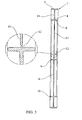
Fig. 1 is a front elevation of a complete hoarding element according to the present invention. -
Fig. 2 is a plan view of the hoarding element. -
Fig. 3 and 4 are respective elevations of each end of the hoarding element. -
Fig. 5 is a cross-section and detail through the indicated sectional planar. -
Fig. 6 is a complete section of the hoarding element according to the invention. -
Fig. 7 is a section of the coupling of a foot of the hoarding element. -
Fig. 8 is a perspective view of the foot and the recess in the hoarding element. -
Fig. 9 and 10 are respective sectional details through the indicated sectional planars. -
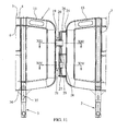
Fig. 11 shows a detail of the coupling of the hoarding elements according to the invention. -
Fig. 12 is a perspective view of a hooking device on one of the sides of the hoarding element. -
Fig. 13 and 14 show respective sectional details of the coupling of the hook elements at one end. -
Fig. 15 is a front elevation of the hoarding element similar to that shown inFig. 1 but of a shorter length. - As shown in the drawings, the hoarding element according to the present invention comprises a principal part moulded in one piece, as indicated by
reference numeral 1, and therotating feet - The
principal element 1 has an elongate structure of variable shape with aflat laminar flange 4 which extends right round the periphery of central body and has a laminar shape so that each of the sections has a double T-shaped structure, as shown inFig. 5 , which illustrates the formation of saidflange 4 by means of a central portion and upper andlower regions body 1.Fig. 5 shows a detail of theshorter cross-bar 8 which has a structure similar to thecross-bars transverse elements slim panel 11 which is joined byattenuated regions 12 forms the upper laminar central portion of the central body. - The
frame 4, in its upper portion, has various transverse apertures such as 13, 14 and 15 intended to act as grips for easy handling of the hoarding element. - It will be appreciated that the number of
cross-bars Fig. 15 shows a hoarding element indicated in its entirety byreference numeral 16 and having a structure similar to that of thehoarding element 1 inFig. 1 , the only significant difference being the length which, in the case illustrated, is much shorter than that of thehoarding element 1 as it has only twocross-bars - A characteristic of the present invention is based on the disposition in one of the smaller sides 19 (
Fig. 1 ) of two substantially U-shaped hooks with unequal arms which originate fromsaid edge 19 and have been indicated byreference numerals Fig. 12 , which shows thehook 20 consisting of a U-shaped structure withunequal arms Fig. 13 and 14 . One of the hooks is directed forward and the other backward from the hoarding element, as shown inFig. 13 and 14 , which show thehooks hoarding element 1 has, on theshorter side 24 remote from theside 19, asingle cross-bar 25 which is joined byupper arm 26 andlower arm 27 and optionally reinforced by anintermediate arm 28 which will have any type of structure,Fig. 13 and 14 showing a cross-section of ribbed shape to achieve greater strength. The coupling of thehooks cross-bar 25 of an adjacent hoarding element is achieved very easily owing to the structure of said hooks and the flexibility of the material, a perfect connection of two successive hoarding elements being obtained. - The feet have a very simple constitution in which a
flattened foot 30 equipped with aninternal counterweight 31 is coupled to the lower region of an externaltubular element 29 introduced into a recess in the lower portion of theelement 1. - The
element 29 has an upperinternal rod 32 which is actually introduced into therecess 33 in the lower portion of the hoarding element, a U-shapedpart 34 held by the cap 38 (Fig. 8 ) being introduced in a corresponding transverse recess, and the lower region comprising sets ofwindows 35 forming two mutually opposed pairs in which projectingresilient ribs foot body 29 can be introduced, thus producing two stable positions of the feet in a perpendicular disposition. - It will be appreciated that with this disposition it is very easy to introduce the hoarding feet elements and to cause them to rotate so as to occupy the desired operating position perpendicular to the hoarding element or transit position parallel thereto.
Claims (6)
- A hoarding element for buildings and the like of the type comprising a moulded body of elongate structure equipped with a plurality of reinforcing cross-bars (7,7',7"), rotating support feet and connecting elements at the ends so as to form a hoarding line for successive coupling of hoarding elements, the hoarding body structure comprising a peripheral rim which extends round the structure, characterised in that one of the smaller sides has two open hooks (20,21) which can be connected to a cross-bar (25) joined to the other smaller side of the adjacent hoarding element so as to lengthen the hoarding elements.
- A hoarding element for buildings and the like according to claim 1, characterised in that the open hooks, in a plan view, have a horizontal U-shaped structure with unequal arms, one of the hooks being directed toward the front face and the other toward the rear face of the hoarding element so as to allow more secure coupling to the cross-bar of the adjacent hoarding element.
- A hoarding element for buildings and the like according to claim 1, characterised in that the cross-bar for joining the smaller side remote from the hooks is a single straight cross-bar joined to the corresponding smaller side of the hoarding element by means of transverse reinforcing arms.
- A hoarding element for buildings and the like according to claim 3, characterised in that said cross-bar has a star-shaped cross-section so as to reduce the mass thereof.
- A hoarding element for buildings and the like according to claim 1, characterised by the provision of apertures in the rim which extends at the periphery of the hoarding element to allow the fastening thereof.
- A hoarding element for buildings and the like according to claim 1, characterised in that the foot elements comprise a base carrying a counterweight and a rod for the introduction thereof into a recess in the lower portion of the hoarding element, having a notch in the upper portion in which there is inserted a U-shaped element which may be press fitted and removed from the exterior by means of a retaining cap and having opposing flexible ribs in the region of its lower portion, which are capable of entering either of two pairs of mating windows in the base of the recess of the hoarding element so as to allow the disposition and fixing of the foot in two mutually perpendicular positions, of which one is perpendicular to the hoarding element and the other parallel thereto.
Applications Claiming Priority (2)
| Application Number | Priority Date | Filing Date | Title |
|---|---|---|---|
| ES200301709U ES1055178Y (en) | 2003-07-17 | 2003-07-17 | FENCE ELEMENT FOR WORKS AND SIMILAR |
| PCT/ES2004/000334 WO2005007972A1 (en) | 2003-07-17 | 2004-07-15 | Barrier element for construction sites and similar |
Publications (3)
| Publication Number | Publication Date |
|---|---|
| EP1647634A1 EP1647634A1 (en) | 2006-04-19 |
| EP1647634B1 true EP1647634B1 (en) | 2010-08-04 |
| EP1647634B9 EP1647634B9 (en) | 2011-01-19 |
Family
ID=29724840
Family Applications (1)
| Application Number | Title | Priority Date | Filing Date |
|---|---|---|---|
| EP04742062A Active EP1647634B9 (en) | 2003-07-17 | 2004-07-15 | Barrier element for construction sites and similar |
Country Status (5)
| Country | Link |
|---|---|
| EP (1) | EP1647634B9 (en) |
| AT (1) | ATE476554T1 (en) |
| DE (2) | DE04742062T1 (en) |
| ES (2) | ES1055178Y (en) |
| WO (1) | WO2005007972A1 (en) |
Families Citing this family (3)
| Publication number | Priority date | Publication date | Assignee | Title |
|---|---|---|---|---|
| GB2455525A (en) * | 2007-12-12 | 2009-06-17 | Tomrods Ltd | Barrier |
| GB2548124A (en) | 2016-03-09 | 2017-09-13 | Oxford Plastic Sys Ltd | Barrier |
| GB2577563B (en) * | 2018-09-28 | 2022-07-20 | Oxford Plastic Sys Ltd | Temporary barrier |
Family Cites Families (6)
| Publication number | Priority date | Publication date | Assignee | Title |
|---|---|---|---|---|
| FR1296138A (en) * | 1961-06-02 | 1962-06-15 | removable fence elements | |
| FR2559804B1 (en) * | 1984-02-16 | 1986-11-07 | Doublet Festitub Sa | METHOD FOR MANUFACTURING A SAFETY BARRIER AND SECURITY BARRIER CARRIED OUT BY IMPLEMENTING THE METHOD |
| ES2146500B1 (en) * | 1996-10-24 | 2001-03-01 | Decoplasctic S A | COUPLABLE AND DISCOVERABLE Fence. |
| US6676113B2 (en) * | 1997-04-22 | 2004-01-13 | Off The Wall Products, Llc | Control barrier with rotatable legs |
| DE69823010T2 (en) * | 1998-05-12 | 2005-03-10 | Construcciones Mecanicas Mares, S.A., Montcada i Reixac | A modular guard rail system element |
| ES1048466Y (en) * | 2001-03-14 | 2001-12-16 | Plastic Fences S A | Fence for closures and signage |
-
2003
- 2003-07-17 ES ES200301709U patent/ES1055178Y/en not_active Expired - Fee Related
-
2004
- 2004-07-15 WO PCT/ES2004/000334 patent/WO2005007972A1/en active Application Filing
- 2004-07-15 DE DE04742062T patent/DE04742062T1/en active Pending
- 2004-07-15 DE DE602004028485T patent/DE602004028485D1/en active Active
- 2004-07-15 ES ES04742062T patent/ES2349926T3/en active Active
- 2004-07-15 EP EP04742062A patent/EP1647634B9/en active Active
- 2004-07-15 AT AT04742062T patent/ATE476554T1/en not_active IP Right Cessation
Also Published As
| Publication number | Publication date |
|---|---|
| WO2005007972A1 (en) | 2005-01-27 |
| ES1055178U (en) | 2003-10-16 |
| DE602004028485D1 (en) | 2010-09-16 |
| EP1647634B9 (en) | 2011-01-19 |
| EP1647634A1 (en) | 2006-04-19 |
| ATE476554T1 (en) | 2010-08-15 |
| DE04742062T1 (en) | 2006-11-16 |
| ES2349926T3 (en) | 2011-01-13 |
| ES1055178Y (en) | 2008-11-01 |
Similar Documents
| Publication | Publication Date | Title |
|---|---|---|
| US6792729B2 (en) | Stackable construction panel system | |
| US4060150A (en) | Ladder kit | |
| KR101680035B1 (en) | Prefabricated Structure | |
| EP1222880A3 (en) | Beam structures for shelving apparatus | |
| KR100932795B1 (en) | Knockdown dome house | |
| US20220241636A1 (en) | Playground climber unit comprising one or more net-containing portions and/or one or more suspended tube portions | |
| EP1647634B1 (en) | Barrier element for construction sites and similar | |
| AU2002257439B2 (en) | Improvements in a stackable construction panel system | |
| KR101533294B1 (en) | Pillar structure for prefabricated pavilion | |
| US20160067624A1 (en) | Playhouse Assembly | |
| US5605396A (en) | Apparatus and method for securing component panels in a tiered lighting fixture | |
| JP2899870B2 (en) | Assembly fence | |
| KR101421678B1 (en) | Assemble type partition | |
| HU219073B (en) | Frame component for vertical platform stages of fixed and/or movable building scaffolding | |
| CN209799292U (en) | Scaffold | |
| KR102184825B1 (en) | joint kit device for furniture assembly | |
| CN206636196U (en) | A kind of self-fastening rod member connector | |
| CN211597092U (en) | Agricultural greenhouse's diagonal draw bar connecting piece | |
| KR102648842B1 (en) | Architectural structure | |
| CN213598327U (en) | A link for indoor paradise | |
| CN208940424U (en) | A kind of multidirectional arrangement formula steps on grain plate and steps on grain channel system | |
| CN216256486U (en) | Light section bar and use its frame curtain frame | |
| CN210670933U (en) | Frame structure and LED display screen | |
| KR200214915Y1 (en) | Steel frame for a square-domed tent | |
| KR102351435B1 (en) | Permanent Beam Form And Manufacturing Method Thereof |
Legal Events
| Date | Code | Title | Description |
|---|---|---|---|
| PUAI | Public reference made under article 153(3) epc to a published international application that has entered the european phase |
Free format text: ORIGINAL CODE: 0009012 |
|
| 17P | Request for examination filed |
Effective date: 20051205 |
|
| AK | Designated contracting states |
Kind code of ref document: A1 Designated state(s): AT BE BG CH CY CZ DE DK EE ES FI FR GB GR HU IE IT LI LU MC NL PL PT RO SE SI SK TR |
|
| AX | Request for extension of the european patent |
Extension state: AL HR LT LV MK |
|
| EL | Fr: translation of claims filed | ||
| DET | De: translation of patent claims | ||
| 17Q | First examination report despatched |
Effective date: 20090720 |
|
| GRAP | Despatch of communication of intention to grant a patent |
Free format text: ORIGINAL CODE: EPIDOSNIGR1 |
|
| GRAS | Grant fee paid |
Free format text: ORIGINAL CODE: EPIDOSNIGR3 |
|
| GRAA | (expected) grant |
Free format text: ORIGINAL CODE: 0009210 |
|
| AK | Designated contracting states |
Kind code of ref document: B1 Designated state(s): AT BE BG CH CY CZ DE DK EE ES FI FR GB GR HU IE IT LI LU MC NL PL PT RO SE SI SK TR |
|
| AX | Request for extension of the european patent |
Extension state: AL HR LT LV MK |
|
| REG | Reference to a national code |
Ref country code: GB Ref legal event code: FG4D |
|
| REG | Reference to a national code |
Ref country code: CH Ref legal event code: EP |
|
| REG | Reference to a national code |
Ref country code: IE Ref legal event code: FG4D |
|
| REF | Corresponds to: |
Ref document number: 602004028485 Country of ref document: DE Date of ref document: 20100916 Kind code of ref document: P |
|
| REG | Reference to a national code |
Ref country code: NL Ref legal event code: VDEP Effective date: 20100804 |
|
| REG | Reference to a national code |
Ref country code: ES Ref legal event code: FG2A Effective date: 20101230 |
|
| LTIE | Lt: invalidation of european patent or patent extension |
Effective date: 20100804 |
|
| PG25 | Lapsed in a contracting state [announced via postgrant information from national office to epo] |
Ref country code: NL Free format text: LAPSE BECAUSE OF FAILURE TO SUBMIT A TRANSLATION OF THE DESCRIPTION OR TO PAY THE FEE WITHIN THE PRESCRIBED TIME-LIMIT Effective date: 20100804 Ref country code: FI Free format text: LAPSE BECAUSE OF FAILURE TO SUBMIT A TRANSLATION OF THE DESCRIPTION OR TO PAY THE FEE WITHIN THE PRESCRIBED TIME-LIMIT Effective date: 20100804 Ref country code: AT Free format text: LAPSE BECAUSE OF FAILURE TO SUBMIT A TRANSLATION OF THE DESCRIPTION OR TO PAY THE FEE WITHIN THE PRESCRIBED TIME-LIMIT Effective date: 20100804 |
|
| PG25 | Lapsed in a contracting state [announced via postgrant information from national office to epo] |
Ref country code: CY Free format text: LAPSE BECAUSE OF FAILURE TO SUBMIT A TRANSLATION OF THE DESCRIPTION OR TO PAY THE FEE WITHIN THE PRESCRIBED TIME-LIMIT Effective date: 20100804 Ref country code: PT Free format text: LAPSE BECAUSE OF FAILURE TO SUBMIT A TRANSLATION OF THE DESCRIPTION OR TO PAY THE FEE WITHIN THE PRESCRIBED TIME-LIMIT Effective date: 20101206 Ref country code: SI Free format text: LAPSE BECAUSE OF FAILURE TO SUBMIT A TRANSLATION OF THE DESCRIPTION OR TO PAY THE FEE WITHIN THE PRESCRIBED TIME-LIMIT Effective date: 20100804 Ref country code: BG Free format text: LAPSE BECAUSE OF FAILURE TO SUBMIT A TRANSLATION OF THE DESCRIPTION OR TO PAY THE FEE WITHIN THE PRESCRIBED TIME-LIMIT Effective date: 20101104 Ref country code: PL Free format text: LAPSE BECAUSE OF FAILURE TO SUBMIT A TRANSLATION OF THE DESCRIPTION OR TO PAY THE FEE WITHIN THE PRESCRIBED TIME-LIMIT Effective date: 20100804 |
|
| PG25 | Lapsed in a contracting state [announced via postgrant information from national office to epo] |
Ref country code: SE Free format text: LAPSE BECAUSE OF FAILURE TO SUBMIT A TRANSLATION OF THE DESCRIPTION OR TO PAY THE FEE WITHIN THE PRESCRIBED TIME-LIMIT Effective date: 20100804 Ref country code: GR Free format text: LAPSE BECAUSE OF FAILURE TO SUBMIT A TRANSLATION OF THE DESCRIPTION OR TO PAY THE FEE WITHIN THE PRESCRIBED TIME-LIMIT Effective date: 20101105 Ref country code: BE Free format text: LAPSE BECAUSE OF FAILURE TO SUBMIT A TRANSLATION OF THE DESCRIPTION OR TO PAY THE FEE WITHIN THE PRESCRIBED TIME-LIMIT Effective date: 20100804 |
|
| PG25 | Lapsed in a contracting state [announced via postgrant information from national office to epo] |
Ref country code: DK Free format text: LAPSE BECAUSE OF FAILURE TO SUBMIT A TRANSLATION OF THE DESCRIPTION OR TO PAY THE FEE WITHIN THE PRESCRIBED TIME-LIMIT Effective date: 20100804 |
|
| PG25 | Lapsed in a contracting state [announced via postgrant information from national office to epo] |
Ref country code: CZ Free format text: LAPSE BECAUSE OF FAILURE TO SUBMIT A TRANSLATION OF THE DESCRIPTION OR TO PAY THE FEE WITHIN THE PRESCRIBED TIME-LIMIT Effective date: 20100804 Ref country code: RO Free format text: LAPSE BECAUSE OF FAILURE TO SUBMIT A TRANSLATION OF THE DESCRIPTION OR TO PAY THE FEE WITHIN THE PRESCRIBED TIME-LIMIT Effective date: 20100804 Ref country code: EE Free format text: LAPSE BECAUSE OF FAILURE TO SUBMIT A TRANSLATION OF THE DESCRIPTION OR TO PAY THE FEE WITHIN THE PRESCRIBED TIME-LIMIT Effective date: 20100804 Ref country code: SK Free format text: LAPSE BECAUSE OF FAILURE TO SUBMIT A TRANSLATION OF THE DESCRIPTION OR TO PAY THE FEE WITHIN THE PRESCRIBED TIME-LIMIT Effective date: 20100804 |
|
| PLBE | No opposition filed within time limit |
Free format text: ORIGINAL CODE: 0009261 |
|
| STAA | Information on the status of an ep patent application or granted ep patent |
Free format text: STATUS: NO OPPOSITION FILED WITHIN TIME LIMIT |
|
| 26N | No opposition filed |
Effective date: 20110506 |
|
| REG | Reference to a national code |
Ref country code: DE Ref legal event code: R097 Ref document number: 602004028485 Country of ref document: DE Effective date: 20110506 |
|
| PG25 | Lapsed in a contracting state [announced via postgrant information from national office to epo] |
Ref country code: MC Free format text: LAPSE BECAUSE OF NON-PAYMENT OF DUE FEES Effective date: 20110731 |
|
| REG | Reference to a national code |
Ref country code: CH Ref legal event code: PL |
|
| GBPC | Gb: european patent ceased through non-payment of renewal fee |
Effective date: 20110715 |
|
| REG | Reference to a national code |
Ref country code: IE Ref legal event code: MM4A |
|
| PG25 | Lapsed in a contracting state [announced via postgrant information from national office to epo] |
Ref country code: LI Free format text: LAPSE BECAUSE OF NON-PAYMENT OF DUE FEES Effective date: 20110731 Ref country code: CH Free format text: LAPSE BECAUSE OF NON-PAYMENT OF DUE FEES Effective date: 20110731 Ref country code: DE Free format text: LAPSE BECAUSE OF NON-PAYMENT OF DUE FEES Effective date: 20120201 |
|
| REG | Reference to a national code |
Ref country code: DE Ref legal event code: R119 Ref document number: 602004028485 Country of ref document: DE Effective date: 20120201 |
|
| PG25 | Lapsed in a contracting state [announced via postgrant information from national office to epo] |
Ref country code: GB Free format text: LAPSE BECAUSE OF NON-PAYMENT OF DUE FEES Effective date: 20110715 |
|
| PG25 | Lapsed in a contracting state [announced via postgrant information from national office to epo] |
Ref country code: IE Free format text: LAPSE BECAUSE OF NON-PAYMENT OF DUE FEES Effective date: 20110715 |
|
| PG25 | Lapsed in a contracting state [announced via postgrant information from national office to epo] |
Ref country code: LU Free format text: LAPSE BECAUSE OF NON-PAYMENT OF DUE FEES Effective date: 20110715 |
|
| PGFP | Annual fee paid to national office [announced via postgrant information from national office to epo] |
Ref country code: IT Payment date: 20130410 Year of fee payment: 10 |
|
| PG25 | Lapsed in a contracting state [announced via postgrant information from national office to epo] |
Ref country code: TR Free format text: LAPSE BECAUSE OF FAILURE TO SUBMIT A TRANSLATION OF THE DESCRIPTION OR TO PAY THE FEE WITHIN THE PRESCRIBED TIME-LIMIT Effective date: 20100804 |
|
| PG25 | Lapsed in a contracting state [announced via postgrant information from national office to epo] |
Ref country code: HU Free format text: LAPSE BECAUSE OF FAILURE TO SUBMIT A TRANSLATION OF THE DESCRIPTION OR TO PAY THE FEE WITHIN THE PRESCRIBED TIME-LIMIT Effective date: 20100804 |
|
| PG25 | Lapsed in a contracting state [announced via postgrant information from national office to epo] |
Ref country code: IT Free format text: LAPSE BECAUSE OF NON-PAYMENT OF DUE FEES Effective date: 20140715 |
|
| REG | Reference to a national code |
Ref country code: FR Ref legal event code: PLFP Year of fee payment: 12 |
|
| REG | Reference to a national code |
Ref country code: FR Ref legal event code: PLFP Year of fee payment: 13 |
|
| REG | Reference to a national code |
Ref country code: FR Ref legal event code: PLFP Year of fee payment: 14 |
|
| PGFP | Annual fee paid to national office [announced via postgrant information from national office to epo] |
Ref country code: FR Payment date: 20170530 Year of fee payment: 14 |
|
| PG25 | Lapsed in a contracting state [announced via postgrant information from national office to epo] |
Ref country code: FR Free format text: LAPSE BECAUSE OF NON-PAYMENT OF DUE FEES Effective date: 20180731 |
|
| PGFP | Annual fee paid to national office [announced via postgrant information from national office to epo] |
Ref country code: ES Payment date: 20230801 Year of fee payment: 20 |