EP1647418B1 - Hub unit with wheel support and bearing ring, and method of manufacturing the hub unit - Google Patents
Hub unit with wheel support and bearing ring, and method of manufacturing the hub unit Download PDFInfo
- Publication number
- EP1647418B1 EP1647418B1 EP05021050A EP05021050A EP1647418B1 EP 1647418 B1 EP1647418 B1 EP 1647418B1 EP 05021050 A EP05021050 A EP 05021050A EP 05021050 A EP05021050 A EP 05021050A EP 1647418 B1 EP1647418 B1 EP 1647418B1
- Authority
- EP
- European Patent Office
- Prior art keywords
- shaft portion
- wheel
- fixing
- portions
- raw material
- Prior art date
- Legal status (The legal status is an assumption and is not a legal conclusion. Google has not performed a legal analysis and makes no representation as to the accuracy of the status listed.)
- Expired - Lifetime
Links
Images







Classifications
-
- B—PERFORMING OPERATIONS; TRANSPORTING
- B21—MECHANICAL METAL-WORKING WITHOUT ESSENTIALLY REMOVING MATERIAL; PUNCHING METAL
- B21J—FORGING; HAMMERING; PRESSING METAL; RIVETING; FORGE FURNACES
- B21J5/00—Methods for forging, hammering, or pressing; Special equipment or accessories therefor
- B21J5/02—Die forging; Trimming by making use of special dies ; Punching during forging
-
- B—PERFORMING OPERATIONS; TRANSPORTING
- B21—MECHANICAL METAL-WORKING WITHOUT ESSENTIALLY REMOVING MATERIAL; PUNCHING METAL
- B21K—MAKING FORGED OR PRESSED METAL PRODUCTS, e.g. HORSE-SHOES, RIVETS, BOLTS OR WHEELS
- B21K1/00—Making machine elements
- B21K1/28—Making machine elements wheels; discs
- B21K1/40—Making machine elements wheels; discs hubs
-
- B—PERFORMING OPERATIONS; TRANSPORTING
- B60—VEHICLES IN GENERAL
- B60B—VEHICLE WHEELS; CASTORS; AXLES FOR WHEELS OR CASTORS; INCREASING WHEEL ADHESION
- B60B27/00—Hubs
-
- B—PERFORMING OPERATIONS; TRANSPORTING
- B60—VEHICLES IN GENERAL
- B60B—VEHICLE WHEELS; CASTORS; AXLES FOR WHEELS OR CASTORS; INCREASING WHEEL ADHESION
- B60B27/00—Hubs
- B60B27/0005—Hubs with ball bearings
-
- B—PERFORMING OPERATIONS; TRANSPORTING
- B60—VEHICLES IN GENERAL
- B60B—VEHICLE WHEELS; CASTORS; AXLES FOR WHEELS OR CASTORS; INCREASING WHEEL ADHESION
- B60B27/00—Hubs
- B60B27/0078—Hubs characterised by the fixation of bearings
- B60B27/0084—Hubs characterised by the fixation of bearings caulking to fix inner race
-
- B—PERFORMING OPERATIONS; TRANSPORTING
- B60—VEHICLES IN GENERAL
- B60B—VEHICLE WHEELS; CASTORS; AXLES FOR WHEELS OR CASTORS; INCREASING WHEEL ADHESION
- B60B27/00—Hubs
- B60B27/0094—Hubs one or more of the bearing races are formed by the hub
-
- F—MECHANICAL ENGINEERING; LIGHTING; HEATING; WEAPONS; BLASTING
- F16—ENGINEERING ELEMENTS AND UNITS; GENERAL MEASURES FOR PRODUCING AND MAINTAINING EFFECTIVE FUNCTIONING OF MACHINES OR INSTALLATIONS; THERMAL INSULATION IN GENERAL
- F16C—SHAFTS; FLEXIBLE SHAFTS; ELEMENTS OR CRANKSHAFT MECHANISMS; ROTARY BODIES OTHER THAN GEARING ELEMENTS; BEARINGS
- F16C19/00—Bearings with rolling contact, for exclusively rotary movement
- F16C19/02—Bearings with rolling contact, for exclusively rotary movement with bearing balls essentially of the same size in one or more circular rows
- F16C19/14—Bearings with rolling contact, for exclusively rotary movement with bearing balls essentially of the same size in one or more circular rows for both radial and axial load
- F16C19/18—Bearings with rolling contact, for exclusively rotary movement with bearing balls essentially of the same size in one or more circular rows for both radial and axial load with two or more rows of balls
- F16C19/181—Bearings with rolling contact, for exclusively rotary movement with bearing balls essentially of the same size in one or more circular rows for both radial and axial load with two or more rows of balls with angular contact
- F16C19/183—Bearings with rolling contact, for exclusively rotary movement with bearing balls essentially of the same size in one or more circular rows for both radial and axial load with two or more rows of balls with angular contact with two rows at opposite angles
- F16C19/184—Bearings with rolling contact, for exclusively rotary movement with bearing balls essentially of the same size in one or more circular rows for both radial and axial load with two or more rows of balls with angular contact with two rows at opposite angles in O-arrangement
- F16C19/186—Bearings with rolling contact, for exclusively rotary movement with bearing balls essentially of the same size in one or more circular rows for both radial and axial load with two or more rows of balls with angular contact with two rows at opposite angles in O-arrangement with three raceways provided integrally on parts other than race rings, e.g. third generation hubs
-
- F—MECHANICAL ENGINEERING; LIGHTING; HEATING; WEAPONS; BLASTING
- F16—ENGINEERING ELEMENTS AND UNITS; GENERAL MEASURES FOR PRODUCING AND MAINTAINING EFFECTIVE FUNCTIONING OF MACHINES OR INSTALLATIONS; THERMAL INSULATION IN GENERAL
- F16C—SHAFTS; FLEXIBLE SHAFTS; ELEMENTS OR CRANKSHAFT MECHANISMS; ROTARY BODIES OTHER THAN GEARING ELEMENTS; BEARINGS
- F16C33/00—Parts of bearings; Special methods for making bearings or parts thereof
- F16C33/30—Parts of ball or roller bearings
- F16C33/58—Raceways; Race rings
- F16C33/64—Special methods of manufacture
-
- F—MECHANICAL ENGINEERING; LIGHTING; HEATING; WEAPONS; BLASTING
- F16—ENGINEERING ELEMENTS AND UNITS; GENERAL MEASURES FOR PRODUCING AND MAINTAINING EFFECTIVE FUNCTIONING OF MACHINES OR INSTALLATIONS; THERMAL INSULATION IN GENERAL
- F16C—SHAFTS; FLEXIBLE SHAFTS; ELEMENTS OR CRANKSHAFT MECHANISMS; ROTARY BODIES OTHER THAN GEARING ELEMENTS; BEARINGS
- F16C2326/00—Articles relating to transporting
- F16C2326/01—Parts of vehicles in general
- F16C2326/02—Wheel hubs or castors
-
- Y—GENERAL TAGGING OF NEW TECHNOLOGICAL DEVELOPMENTS; GENERAL TAGGING OF CROSS-SECTIONAL TECHNOLOGIES SPANNING OVER SEVERAL SECTIONS OF THE IPC; TECHNICAL SUBJECTS COVERED BY FORMER USPC CROSS-REFERENCE ART COLLECTIONS [XRACs] AND DIGESTS
- Y10—TECHNICAL SUBJECTS COVERED BY FORMER USPC
- Y10T—TECHNICAL SUBJECTS COVERED BY FORMER US CLASSIFICATION
- Y10T29/00—Metal working
- Y10T29/49—Method of mechanical manufacture
- Y10T29/49481—Wheel making
- Y10T29/49492—Land wheel
- Y10T29/49533—Hub making
-
- Y—GENERAL TAGGING OF NEW TECHNOLOGICAL DEVELOPMENTS; GENERAL TAGGING OF CROSS-SECTIONAL TECHNOLOGIES SPANNING OVER SEVERAL SECTIONS OF THE IPC; TECHNICAL SUBJECTS COVERED BY FORMER USPC CROSS-REFERENCE ART COLLECTIONS [XRACs] AND DIGESTS
- Y10—TECHNICAL SUBJECTS COVERED BY FORMER USPC
- Y10T—TECHNICAL SUBJECTS COVERED BY FORMER US CLASSIFICATION
- Y10T29/00—Metal working
- Y10T29/49—Method of mechanical manufacture
- Y10T29/49636—Process for making bearing or component thereof
- Y10T29/49643—Rotary bearing
- Y10T29/49679—Anti-friction bearing or component thereof
- Y10T29/49689—Race making
-
- Y—GENERAL TAGGING OF NEW TECHNOLOGICAL DEVELOPMENTS; GENERAL TAGGING OF CROSS-SECTIONAL TECHNOLOGIES SPANNING OVER SEVERAL SECTIONS OF THE IPC; TECHNICAL SUBJECTS COVERED BY FORMER USPC CROSS-REFERENCE ART COLLECTIONS [XRACs] AND DIGESTS
- Y10—TECHNICAL SUBJECTS COVERED BY FORMER USPC
- Y10T—TECHNICAL SUBJECTS COVERED BY FORMER US CLASSIFICATION
- Y10T74/00—Machine element or mechanism
- Y10T74/20—Control lever and linkage systems
- Y10T74/20576—Elements
- Y10T74/20636—Detents
- Y10T74/20672—Lever engaging rack
- Y10T74/20696—Finger lever release
Definitions
- the present invention relates to a wheel support hub unit adapted to support rotatably a wheel of, for example, an automobile on a suspension unit, a bearing ring member for a wheel support hub unit, and a method of manufacturing the same.
- a wheel of an automobile and the like is supported rotatably on a wheel support hub unit fixed to a suspension unit for a vehicle body.
- the wheel support hub unit is provided with a plurality of rolling elements interposed between an inner member and an outer member, which have raceway surfaces, the inner member and outer member being provided with fixing flanges to be fixed to the suspension unit for the wheel or vehicle body.
- a positioning unit adapted to position the wheel is provided on a side of the fixing flanges.
- the surface area of the fixing flanges is large, and a very large forming load is needed in the cold forging process, so that the hot forging process is generally carried out.
- the dimensional accuracy is low, and a decarbonization removal operation is necessary in some cases in a thermal treatment unit. Since a large cutting margin is necessary in a later process, the manufacturing cost increases.
- a hub ring 6' shown in Fig. 14 and an outer ring 3 shown in Fig. 15 are known as a bearing ring member constituting the inner member and outer member in which consideration is given to the reduction of the weight thereof and the retention of the strength thereof.
- the hub ring 6' is provided with a solid shaft portion 5' and radial wheel fixing flanges 7' extending in the direction crossing the shaft portion 5' at right angles thereof.
- a plurality of fixing portions 21' are formed to a large thickness, and, among the fixing portions 21', web-shaped small-thickness portions 22' are formed.
- the outer ring 3 is provided with a hollow shaft portion 15, and a suspension unit fixing flanges 18 extending in the direction crossing the shaft portion 15 at right angles thereto, the suspension unit fixing flanges 18 being made heteromorphous at an outer circumferential portion thereof.
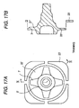
- bearing ring members are made by related art methods as shown in Fig. 16 , by forming small-thickness portions 22' by expanding the excess parts among the fixing sections 21' of the wheel fixing flanges 7' by a hot forging operation, and then cutting off unnecessary parts 123 by subjecting the small-thickness portions 22' to a trimming process as shown in Fig. 17 .
- the positioning portion is formed separately from the bearing ring member, so that the positional accuracy and a degree of right angle of the positioning portion and raceway surface on the side of the bearing ring member is liable to lower. Moreover, the number of parts increases to cause the manufacturing cost to be heightened. Furthermore, since a bearing ring member including fixing flanges cannot be cold formed, a cutting margin in a later step is large, so that the manufacturing cost increases.
- the bearing ring members shown in Figs. 6 and 7 are manufactured by the hot forging, the above-mentioned problems are included.
- Such parts of the bearing ring members that are pressed to a small thickness extend greatly toward the outer circumferential side thereof, so that the quantity of excess thickness becomes large to cause the yield to lower.
- the excess thickness is large, the surface area of the upset portion increase, and the forming load increases. For these reasons, it becomes disadvantageous in particular to form such a heteromorphous flanges by the cold forging in which the stress becomes high.
- a wheel support hub unit comprising a bearing ring member and a method of manufacturing said bearing member is e.g. known from DE 2 233 966 .
- this document relates to a method and apparatus for manufacturing a hub shell for a single-lane vehicle such as a bicycle by plastic deformation and discloses a bearing member comprising wheel support fixing portions extending radially outward from a hollow shaft portion and a wheel or vehicle body positioning cylinder provided concentrically with said shaft portion. Further, said document discloses that the bearing ring member is formed by placing a raw material being formed to a predetermined shape in advance in a die having grooves extending radially outward.
- the raw material is pressed such that the raw material flows in the grooves of the die, thereby forming the fixing portions integral with the shaft portion by side extrusion.
- the die used for forming the fixing portions has a bore which corresponds to an outer circumference of a positioning cylindrical portion, with the height of the fixing portions left on the head portion.
- the fixing portions being provided with fixing holes for mounting thereto spokes which are connected in the pitch circle of the fixing holes and form a discoidal fixing flange for the plurality of spokes to be mounted accordingly.
- a method for manufacturing a hub shell for bicycles is likewise known from DE 22 42 531 .
- an object of the present invention is to provide an inexpensive bearing ring member for a wheel support hub unit.
- the present invention is made so as to eliminate such inconveniences, and an object of the invention is to provide an inexpensive wheel support hub unit, a bearing ring member of the wheel support hub unit, and a method of manufacturing the same, capable of forming a positioning member into a circumferentially continuous cylindrical integral member, and forming fixing flanges to small weight by the cold forging without carrying out a proc-ess, such as a bending process.
- the present invention provides a method as defined in claim 1.
- the fixing portions are formed with the shaft portion in one body by the cold side extrusion. Therefore, even when the extrusion length, i.e. the area of the fixing portions increases, the forming load does not vary, and the forming operation can be carried out with a small load as compared with the case where the fixing portions are compression formed. This enables the forming operation to be carried out by using comparatively small equipment by the cold forging, a cutting margin occurring in the later stage to be reduced, and the inexpensive bearing ring member and wheel support hub unit to be obtained.
- a joint portion between the fixing portions and an outer circumferential portion of the bearing ring member is not subjected to a bending process, so that a sufficient thickness can be secured in the joint portion. This enables the bearing member and wheel support hub unit having a sufficient strength to be obtained.
- the fixing portions are formed by the sideway extrusion, the extrusion remaining portion can be used as the positioning cylindrical portion. Therefore, the circumferentially continuous positioning cylindrical portions can be formed easily and highly accurately with the shaft portion in one body. When the positioning cylindrical portion is formed separately, a required fixing excess thickness becomes unnecessary, and a material yield in the condition in which the thickness of the required portion is secured can be improved. This enables the manufacturing cost to be reduced.
- the bearing ring member is formed by the cold forging including a step of extrusion forming out of a solid or hollow shaft raw material a shaft portion and a head portion having a shape of an inner circumference of a positioning cylindrical object, and a upsetting step for forming fixing portion by upsetting the head portion with the height of the fixing portions kept thereon, by using a die provided with a bore the diameter of which corresponds to that of an outer circumference of the positioning cylindrical portion. Therefore, when the upset-forming of the fixing portions during which the highest processing load is imparted is done, the part of the positioning cylindrical portion which is on the inner side of the outer circumference thereof does not need to be compressed. This enables the fixing portions to be formed with a lower upsetting surface and lower load as compared with those in the case where the material as a whole is upset.
- the fixing portions can be formed by the cold forging using comparatively small equipment. Therefore, a cutting processing margin used in a later process can be reduced, and an inexpensive bearing ring member and a wheel support hub unit can be obtained. Since a joint portion between the fixing portions and the outer circumferential portion of the bearing ring member is not subj ected to a bending process, a sufficient thickness of the joint portion can be secured, and a bearing ring member and a wheel support hub unit which have a sufficient strength can be obtained.
- the inner circumferential side portion of the raw material can be formed as a positioning cylindrical portion during the upsetting process, the circumferentially continuous positioning cylindrical portion can be formed so as to be integral with the shaft portion accurately with ease. Moreover, when the positioning cylindrical portion is formed separately, the excess thickness needed for the fixing operation in the above-described case becomes unnecessary, so that the material yield can be improved with the thickness of the necessary portion secured. This enables the manufacturing cost to decrease.
- the outer circumferential shape of the head portion not yet subjected to the upsetting step is set to a heteromorphous shape, the surface area of the upset portion during a upsetting process decreases, so that the forming load can be held down to a low level.
- the small thickness portion only is upset, the outer circumference of the upset portion can be reduced, so that the forming load can be reduced to a low level.
- the quantity of the portion to be trimmed of the outer circumference decreases, so that the yield can be improved.
- a wheel support hub unit 1 is used as a driven wheel, and provided with a bearing unit having a hub (inner member) 2, an outer ring (outer member) 3 as a bearing ring member, and a plurality of rolling elements 4.
- the hub 2 is provided with a hub wheel 6 including a solid shaft portion 5 as a bearing ring member.
- the hub wheel 6 is provided at an outboard-side end portion (outer end portion (left end portion in Fig. 1 ) in the widthwise direction of the vehicle in a vehicle combined state) of the outer circumferential surface thereof with wheel fixing flanges 7 constituting the fixing portions extending in the radially outward direction which crosses the shaft portion 5 at right angles thereto.
- the wheel fixing flanges 7 are provided on the outboard-side surface thereof with a plurality of studs 8 implanted therein at substantially equal intervals so as to fix a wheel, brake rotors and the like thereto.
- Each of the wheel fixing flange 7 is provided with fixing holes 7a, and formed so that the wheel fixing flanges 7 are not connected together in the positions of the pitch circles of the wheel fixing holes 7a.
- the hub wheel 6 is provided at the outboard side of the wheel fixing flanges 7, i.e., at the opposite side of the shaft portion 5 via the wheel fixing flanges 7 with a wheel positioning cylindrical portion 9 projecting concentrically with the shaft portion 5.
- the hub wheel 6 is provided at an inboard side end portion (inside end portion in the vehicle widthwise direction in a vehicle-combined state, i.e., at the right end portion in Fig. 1 ) with a small-diameter stepped portion 10, in which an inner race 11 is fitted.
- the inner race 11 is provided on an outer circumferential side thereof with an inner raceway surface 12, and on an outer circumferential side of an axially intermediate portion of the hub wheel 6 with an inner raceway surface 13.
- a front end at the inboard side of the hub wheel 6 is formed cylindrically, and the cylindrical portion (portion to be calked) 14 is calk-expanded radially outward.
- the inner race 11 is thereby calk-fixed to the hub wheel 6.
- the inner race 11 can be subjected to the application of necessary pre-pressurization by a nut (not shown) fastened to the inboard side end surface of the hub wheel 6 in addition to the calk-fixing techniques.
- An outer race 3 is formed so as to include a hollow shaft portion 15.
- the inner circumferential side of the outer race 3 is provided with an outer raceway surface 16 opposed to the inner raceway surface 13 of the hub wheel 6, and an outer raceway surface 17 opposed to an inner raceway surface 12 of the inner race 11.
- the end portion of the outer race 3 which is away from the wheel fixing flange 7 is provided with a plurality of suspension unit fixing flanges 18, which constitute fixing portions extending in the direction crossing the shaft portion 15 at right angles thereto in a radially outward position.
- Each of the suspension unit fixing flanges 18 is provided with a fixing hole 18a, and formed so that these flanges are not connected to one another in a pitch circle of these fixing holes 18a of the suspension unit fixing flanges 18.
- the outer ring 3 is provided at the inboard side of the suspension unit fixing flanges 18 thereof, i.e., the portion thereof which is on the opposite side of the shaft portion 15 via the suspension fixing flange 18 with a vehicle body positioning cylindrical portion 19 formed concentrically with the shaft portion 15.
- a plurality of rolling elements 4 are arranged rollably in the circumferential direction via retainers 20 between a plurality of rows of inner raceway surfaces 12, 13 and a plurality of outer raceway surfaces 16, 17.
- balls are used as the rolling elements 4.
- taper rollers are used sometimes as the rolling elements 4.
- the suspension unit fixing flanges 18 of the outer race 3 are fixed to the suspension unit, and a brake rotor and a wheel are secured to the wheel fixing flanges 7 of rotary ring side hub ring 6 via studs 8 and nuts (not shown), etc.
- the wheel fixing flanges 7 extending in the radial direction which is at right angles to the shaft portion 5 are formed by the cold side extrusion so that these flanges 7 are integral with the shaft portion 5, and the positioning cylindrical portion 9 formed of the extrusion remaining portion occurring during the forming operation is also provided concentrically with the shaft portion 5 so that the cylindrical portion 9 is integral with the shaft portion 5.
- the suspension unit fixing flanges 18 extending in the radial direction which is at right angles to the shaft portion 15 are formed by the cold side extrusion so that the suspension unit fixing flanges 18 are integral with the shaft portion 15, and the positioning cylindrical portion 19 formed by the extrusion remaining portion occurring during the forming operation is also provided concentrically with the shaft portion 15 so that the cylindrical portion 19 is integral with the shaft portion 15.
- Figs. 4 to 6 show an example of a process for cold forging the hub ring 6.
- a solid rod material 30 of Fig. 4A is subjected to the forward extrusion forming to thereby form a shaft-like member 30a of Fig. 4B .
- a head portion of the shaft-like member 30a is then pressed by heading the same to an outer diameter substantially equal to that ⁇ D of the positioning cylindrical portion 9.
- a shaft portion element 30b shown in Fig. 4C is formed.
- This shaft portion element 30b is further subjected to the side extrusion in the direction which is at right angles to the direction of the extrusion using a form 50 shown in Fig. 6 .
- the hub ring 6 made integral of the wheel fixing flanges 7 and positioning cylindrical portion 9 is formed as shown in Figs. 4D and 5 .
- a solid shaft portion element is used.
- a hub ring for the driving wheel can be formed in the same manner.
- Fig. 6 shows a form 50 used in a side extrusion process for producing the hub ring 6, and Fig. 6A the same form in a raw material inserted state, Fig. 6B showing the same form in a material forming state.
- This form 50 is provided with a lower die 52 into which an inboard side end section of a shaft portion material 30b is inserted, and an upper die 51 urged toward the lower die by an elastic member 56.
- the upper die 51 is provided with a bore 57 the diameter of which is substantially equal to the outer diameter ⁇ D of the positioning cylindrical portion 9, and the outboard side end section (head section) of the shaft portion raw material 30b is provided in the bore 57.
- the part of the interior of the bore 57 which is on the upper side of the head section is provided with a ring punch 55 and a punch 54 are so that these punches are slidable.
- the ring punch 55 and punch 54 are fixed to the upper form 58 to which the upper die 51 is fixed via the elastic member 56.
- the radial grooves 53 may be formed in the upper die 51 or the lower die 52 alone.
- the punch 54 forms a recess in an upper surface of the head section of the shaft portion raw material 30b and compresses the same in the axial direction to cause an outer circumferential portion of the head section of the shaft portion raw material 30b to be extruded into the radial grooves in the direction (sideways) which is at right angles to the direction in which the punch advances.
- the wheel fixing flanges 7 are thereby formed so as to be integral with the shaft portion 5 with the extrusion remaining portion of the head section of ⁇ D which occurs during the forming operation becoming the positioning cylindrical portion 9.
- the forming load is imparted to only the inner surface of the head section, and does not have influence on the length (surface area). Therefore, when the length (surface area) of the wheel fixing flanges 7 is large, the flanges can be formed with a very small forming load as compared with that in the case where the wheel fixing flanges 7 are compression formed.
- a hollow cylindrical shaft portion raw material 40 of Fig. 7A (this shaft portion raw material can be obtained by removing the bottom by the draw forming or by removing the bottom by the rearward extrusion forming, and the like in addition to a seam welded pipe cutting method) is subjected to the side extrusion using a form shown in Fig. 9 , in the direction which is at right angles to the pushing direction to thereby form an integral combination of the suspension unit fixing flanges 18 and positioning cylindrical portion 19 as shown in Fig. 7B and 8 .
- a stepped portion 41 opposed to the outer ring raceway surface 16 is then formed on the end portion inner surface on the outboard side as shown in Fig. 7C to form the outer ring 3.
- Fig. 9 shows a form 70 used for a side extrusion process for obtaining the outer ring 3, wherein Fig. 9A shows a raw material inserting state, and Fig. 9B a forming state.
- This form 70 is provided with a lower die 72 into which an end portion on the outboard side of a shaft portion element 40 is inserted, and an upper die 71 adapted to be urged toward the lower die 72 by an elastic member 76.
- the upper die 71 is provided with a bore 77 the diameter of which is substantially equal to an outer diameter ⁇ D0 of a positioning cylindrical portion 19, and an end portion of an inboard side of a shaft portion raw material 40 is placed in the bore 77.
- a ring punch 75 and a punch 74 are provided slidably, and these punches are fixed to the upper form 78 to which the upper die 71 is secured via the elastic member 76.
- a mandrel 74a the diameter of which is substantially equal to an inner diameter ⁇ D1 of the shaft portion raw material 40 is provided so as to restrain the cylindrical shaft portion raw material 40.
- radial grooves extending in the radially outward direction are provided between the end surfaces of the upper die 71 and lower die 72.
- the radial grooves 73 may be formed in the upper die 71 alone or in the lower die 72 alone.
- the punch 74 forms first a stepped portion 42, which is opposed to an outer ring raceway surface 17, on an inner surface of an end portion on the shaft portion raw material 40.
- the ring punch 75 then contacts the inboard side end surface of the shaft portion raw material 40 and compresses the same in the axial direction (sideways).
- an outer circumferential portion of the shaft portion raw material 40 is extruded into the radial grooves 73 in the direction (sideways) which is at right angles to the direction in which the punch advances, and a suspension unit fixing flanges 18 are formed in one body with the shaft portion 15, an extrusion remaining portion of the diameter ⁇ D0 occurring during the forming operation becoming a positioning cylindrical portion 19.
- the forming load is imparted to the ring-shaped portion only of ⁇ D0 to ⁇ D1 of the shaft portion raw material, is not influenced by the length (surface area) of the suspension unit fixing flanges 18. Therefore, the suspension unit fixing flanges 18 having a large length (surface area) can be formed with an extremely small forming load as compared with the forming load in the case where such flanges 18 are compression formed.
- the lower die 72 may be made vertically movable just as the upper die 71, and may be urged toward the upper die 71 via an elastic member (upper and lower die-floating structure).
- the wheel fixing flanges 7 of the hub ring 6 are formed with the solid shaft portion 5 in one body by the cold side extrusion, and the suspension unit fixing flanges 18 of the outer ring 3 with the hollow shaft portion 15 in one body by the cold side extrusion. Therefore, even when the extrusion length (surface area) of the wheel fixing flanges 7 and suspension unit fixing flanges 18 becomes large, the forming load does not vary owing to the features of the extrusion forming. This enables the wheel fixing flanges 7 and suspension unit fixing flanges 18 to be formed with a low load by the cold forging using comparatively small equipment as compared with such flanges 7, 18 fixing flange 7 and suspension unit fixing flanges 18 compression formed.
- the joint portion between the wheel fixing flanges 7 and the outer circumferential portion of the hub ring 6 and the joint portion between the suspension unit fixing flanges 18 and outer circumferential portion of the outer ring 3 are not subjected to a bending process. Therefore, a sufficient thickness of these joint portions can be secured, and the hub ring 6 and outer ring 3 of a sufficiently large strength can be obtained.
- the extrusion remaining portions can be used as the wheel positioning cylindrical portion 9 and vehicle body positioning cylindrical portion 19. This enables the circumferentially continuous cylindrical positioning portions 9, 19 to be cold formed with the shaft portions 5, 15 in one body easily with a high accuracy. Moreover, excess fixing portions, which are necessary when these positioning cylindrical portions 9, 19 are formed separately, become unnecessary, so that it becomes possible to improve the material yield with the thickness of the necessary portions secured, and thereby reduce the manufacturing cost.
- raceway ring member for the wheel support hub unit for the inner ring rotating driven wheel is shown.
- the present invention may, of course, be applied to the wheel support hub units for an inner ring rotating driving wheel, an outer ring rotating driven wheel, or an outer ring rotating driving wheel.
- a plurality of rows of rolling bearings around which the outer ring 3 is fitted, are illustrated as the bearing portion thereof.
- the present invention may be applied to the raceway member of a wheel support hub unit employing a plurality of rows of rolling bearings the inner rings of which are divided at substantially an axially central portions thereof besides two rows of single-line angular ball bearings and two rows of single-line conical rolling bearings instead of the bearings illustrated above.
- the hub ring 6 for a driving wheel which is a bearing ring member of the wheel support hub unit 1 will be taken as an example, and a method of manufacturing the same will be described.
- a hollow cylindrical shaft portion raw material 30 is subjected to forward extrusion forming to form a shaft portion member 30a of Fig. 10B .
- a head portion of the shaft portion member 30a member is then upset to form a shaft portion member 30b shown in Fig. 10C .
- This shaft portion member 30b is subjected to a head portion rearward extrusion forming to form a head portion 132 having a stepped recess 31 forming the shapes of the inner circumferences of the shaft portion 5 and positioning cylindrical portion 9.
- the head portion 132 is then upset so that that the height of the wheel fixing flanges 7 remains by using the form 40 shown in Fig. 11 , to form the wheel fixing flanges 107.
- the form 40 is provided with a lower die 41 having an inner circumferential surface the diameter of which is substantially equal to that of the outer circumferential surface of the shaft portion 5, an upper die 43 having a bore 42 the diameter of which corresponds to that of an outer circumference D of the positioning cylindrical portion 9, and a radial deformation preventing guide member 44 engaged with the upper die 43 and engageable with the inner circumferential surface of the positioning cylindrical portion 9.
- the upper die 43 does not contact the part of the positioning cylindrical portion 9 which has a diameter smaller than that of the outer circumference D of the positioning cylindrical portion 9, and the outer part only of the positioning cylindrical portion 9 is upset.
- the height H of the head portion does not vary, so that the positioning cylindrical portion 9 is formed simultaneously with the wheel fixing flanges 7.
- the radial deformation preventing guide member 44 is fitted in the inner circumference of the recess 31 of the positioning cylindrical portion 9, the end surface of the guide member 44 is not brought into contact with a bottom surface of the positioning cylindrical portion 9.
- the manufacturing method in this embodiment can also be applied when an outer ring and a hub ring for a driven wheel are manufactured.
- a shaft portion 5 and a recess 31 are extrusion formed out of a hollow shaft portion raw material 30, and a head portion 132 is thereafter upset with the height of the wheel fixing flange 7 left thereon, by using the upper die 43 having a bore 42 the diameter of which corresponds to the outer circumference of the positioning cylindrical portion 9.
- the part of the positioning cylindrical portion 9 which is on the inner side of the outer circumference thereof is not necessary to be compressed. Therefore, as compared with a case where the wheel fixing flanges 7 as a whole are upset, the surface area to be upset decreases, so that the wheel fixing flanges 7 can be formed with a low load.
- the inner circumferential side of the upper form 43 can be used to form the positioning cylindrical portion 9. Therefore, the circumferentially continuous cylindrical positioning portion 9 can be formed with the shaft portion 5 in one body easily with a high accuracy. Moreover, excess thickness for carrying out a necessary fixing operation becomes unnecessary when the positioning cylindrical portion 9 is formed separately, the material yield can be improved with the thickness of a necessary portion secured. This enables the manufacturing cost to be reduced.
- a method of manufacturing a bearing ring member of a wheel support hub unit in a third embodiment of the present invention will now be described in detail with reference to Fig. 12 with the outer ring 3 for the driving wheel in the second embodiment as a bearing ring member.
- a hollow cylindrical shaft portion raw material 50 is subjected to the forward extrusion forming to form a shaft portion member 50a having a head portion 52 provided with a recess 51 forming an inner circumferential shape of a shaft portion 15 and positioning cylindrical portion Y19 of Fig. 12B .
- a head portion 152 is then formed to a heteromorphous outer circumferential shape having radial projections 53 the number of which is equal to that of fixing holes 118a provided in a suspension unit fixing flanges 18.
- the head portion 52 is then upset with the shaft portion 15 held in the lower die (not shown) and with the head portion 52 left at the height of the suspension unit fixing flanges 18 without restraining an outer circumference, by using an upper die (not shown) having a bore the diameter of which corresponds to the outer circumference D of the positioning cylindrical portion 19 to form the suspension unit fixing flanges 18.
- the head portion 52 i.e. an intermediate element in the heteromorphous upsetting step is heteromorphous, so that the suspension unit fixing flanges 18 upset in the upsetting step is also heteromorphous with the upsetting surface area becoming required minimum. Therefore, a forming load becomes low, and the height H of the head portion 52 does not vary, so that the positioning cylindrical portion 19 is formed at the same time.
- a stepped portion forming step (thinning step) shown in Fig. 12E , interposed parts of circumferentially adjacent radial projections 142 are upset to smaller thickness to cause unnecessary parts of the suspension unit fixing flanges 18 to be formed as small thickness portions 54. As shown in Fig. 12F , an excess thickness portion is then removed by trimming, and an outer ring 103 is thus manufactured. Since the upsetting operation in the stepped portion forming step is applied to the small thickness portions 54, and the other portions are not compressed, so that the forming load can be reduced.
- the manufacturing method in this embodiment can also be applied when a hub ring for a driving wheel, and a hub ring for a driven wheel are manufactured.
- the outer circumferential shape of the head portion 152 having the radial projections 53 is set heteromorphous in the heteromorphous head portion forming step, so that the outer circumference of the suspension unit fixing flanges 18 not yet upset can be set heteromorphous.
- the surface area of the portion to be upset decreases during the upsetting process enable the forming load to be held down to a low level.
- the forming load can be held down to a low level since the outer circumference can be reduced after the circumference is upset.
- the yield can be improved.
- a method of manufacturing a bearing ring member of a wheel support hub unit in a forth embodiment of the present invention will now be described in detail with reference to Fig. 13 with a hub ring 6' for a driven wheel shown in Fig. 14 taken as an example of a bearing ring member.
- a solid shaft portion raw material 60 shown in Fig. 13A is subjected to extrusion forming to form a shaft portion member 60a shown in Fig. 13B .
- a head portion of the shaft portion member 60a is then upset to form a shaft portion member 60b shown in Fig. 13C .
- the shaft portion member 60b is then subjected to a head portion rearward extrusion forming as shown in Fig. 13D , to form a recess 61 which is to form an inner circumferential shape of a shaft portion 5' and positioning cylindrical portion 9'.
- the head portion 62 is formed as the outer circumference thereof is swelled to a heteromorphous shape.
- an outer circumferential shape having radial projections 63 the number of which is equal to that of fixing holes 7a' provided in wheel fixing flanges 7' is formed.
- the head portion 62 is then upset in accordance with a upsetting step of Fig. 13E with the height H of the wheel fixing flanges 7' left on the head portion 62 without restraining an outer circumference thereof with the shaft portion 5' held in a lower die (not shown), by using an upper die (not shown) having a bore of a circumferential length corresponds to an outer circumference D of the positioning cylindrical portion 9', and the wheel fixing flanges 7' are thereby formed.
- the wheel fixing flanges 7' upset in the upsetting step also becomes heteromorphous since the head portion of an intermediate material in the head portion rearward extrusion step has a heteromorphous shape.
- the upsetting surface area comes to be at a required minimum level, so that a forming load becomes low. Since the height H does not vary, the positioning cylindrical portion 9' is formed at the same time.
- a stepped portion forming step (thinning step) shown in Fig. 13F
- the portions among the circumferentially adjacent radial projections 63 are upset, and the thickness of unnecessary portions of the wheel fixing flanges 7' is thereby set smaller.
- Excess thickness portions are then removed by carrying out a trimming process shown in Fig. 13G to manufacture a hub ring 6'.
- the upsetting operation in the stepped portion forming step is applied to only the portions, which are to form smaller thickness portions, and the other portions are not compressed, so that the forming load can be lowered.
- wheel fixing flanges 7' of different thickness and small thickness portions 22' are formed.
- the manufacturing method in this embodiment can also be applied to cases where the outer ring and hub ring for a driving wheel are manufactured.
- a head portion 62 having a shaft portion 5' and a recess 61 is formed in the head portion rearward extrusion step, in which the outer circumferential shape of the head portion 162 having radial projections 63 is at the same time set heteromorphous.
- the outer circumferential shape of the wheel fixing flanges 7' not yet upset is thereby set heteromorphous, so that the surface area of the part to be upset during a upsetting process decreases, a forming load being thereby rendered able to be held down to a low level.
- the forming load can be held down to a low level since the outer circumference of the same flanges upset can be reduced. Furthermore, since the quantity to be trimmed of the outer circumference decreases, the yield can be improved.
- a plurality of rows of rolling bearings around an end portion of the hub ring 6 for which the outer ring 103 is fitted are shown as examples of bearing portions.
- the present invention may also be suitably applied to a bearing ring member of a wheel support hub unit employing a plurality of rows of rolling bearings in which an inner ring is divided into two at a substantially axially intermediate portion thereof in addition to a bearing ring member having two rows of single-row angular ball bearings or two rows of single-row conical rolling bearings instead of the rolling bearings shown as examples in the embodiments.
- a driving wheel member of a wheel support hub unit for an inner ring rotating driving wheel and a driving wheel member of a wheel support hub unit for an inner ring rotating driven wheel are shown as examples.
- the present invention may, of course, be applied to a bearing ring member of a wheel support hub unit for an outer ring rotating driven wheel or an outer ring rotating driving wheel.
Landscapes
- Engineering & Computer Science (AREA)
- Mechanical Engineering (AREA)
- General Engineering & Computer Science (AREA)
- Manufacturing & Machinery (AREA)
- Rolling Contact Bearings (AREA)
Abstract
Description
- The present invention relates to a wheel support hub unit adapted to support rotatably a wheel of, for example, an automobile on a suspension unit, a bearing ring member for a wheel support hub unit, and a method of manufacturing the same.
- A wheel of an automobile and the like is supported rotatably on a wheel support hub unit fixed to a suspension unit for a vehicle body. The wheel support hub unit is provided with a plurality of rolling elements interposed between an inner member and an outer member, which have raceway surfaces, the inner member and outer member being provided with fixing flanges to be fixed to the suspension unit for the wheel or vehicle body. A positioning unit adapted to position the wheel is provided on a side of the fixing flanges.
- When the inner member and outer member as bearing ring members are manufactured, the surface area of the fixing flanges is large, and a very large forming load is needed in the cold forging process, so that the hot forging process is generally carried out. However, in the hot forging process, the dimensional accuracy is low, and a decarbonization removal operation is necessary in some cases in a thermal treatment unit. Since a large cutting margin is necessary in a later process, the manufacturing cost increases.
- Under the circumstances, a related art bearing ring member manufacturing method in which fixing flanges are cut and raised from an intermediate raw material formed by cold forging a cylindrical pipe as a base material with the portions left after the cutting and raising operations used as positioning portions (refer to, for example, the Patent Document 1), and a related art bearing ring member manufacturing method in which positioning portions are formed separately from the bearing ring member and fixed to the bearing ring member (refer to, for example, to the Patent Document 2) are proposed.
- A hub ring 6' shown in
Fig. 14 and anouter ring 3 shown inFig. 15 are known as a bearing ring member constituting the inner member and outer member in which consideration is given to the reduction of the weight thereof and the retention of the strength thereof. The hub ring 6' is provided with a solid shaft portion 5' and radial wheel fixing flanges 7' extending in the direction crossing the shaft portion 5' at right angles thereof. In the wheel fixing flanges 7', a plurality of fixing portions 21' are formed to a large thickness, and, among the fixing portions 21', web-shaped small-thickness portions 22' are formed. Theouter ring 3 is provided with ahollow shaft portion 15, and a suspensionunit fixing flanges 18 extending in the direction crossing theshaft portion 15 at right angles thereto, the suspensionunit fixing flanges 18 being made heteromorphous at an outer circumferential portion thereof. - These bearing ring members are made by related art methods as shown in
Fig. 16 , by forming small-thickness portions 22' by expanding the excess parts among the fixing sections 21' of the wheel fixing flanges 7' by a hot forging operation, and then cutting off unnecessary parts 123 by subjecting the small-thickness portions 22' to a trimming process as shown inFig. 17 . - [Patent Document 1]
JP-A-2003-25803 - [Patent Document 2]
JP-A-2003-291604 - [Patent Document 3]
JP-A-2004-74815 - However, in the invention disclosed in the
above Patent Publication 1, a bending process is carried out when a joint portion between the fixing flanges, which need the highest strength, and the outer circumferential portion of the bearing ring member is cut and raised, flaws, such as cracks being liable to occur, the strength of the joint portion becoming unstable. Moreover, since the joint portion has to be rendered easily bendable, it is impossible to reinforce this portion by, for example, increase the thickness thereof and the like. Since the positioning portion is not formed to a circumferentially continuous cylindrical shape, the positioning operation becomes unstable. The strength of the joint portion is not sufficiently high, either. - In the patent disclosed in the
above Patent Document 2 and that disclosed in thePatent Document 3, the positioning portion is formed separately from the bearing ring member, so that the positional accuracy and a degree of right angle of the positioning portion and raceway surface on the side of the bearing ring member is liable to lower. Moreover, the number of parts increases to cause the manufacturing cost to be heightened. Furthermore, since a bearing ring member including fixing flanges cannot be cold formed, a cutting margin in a later step is large, so that the manufacturing cost increases. - The bearing ring members shown in
Figs. 6 and7 are manufactured by the hot forging, the above-mentioned problems are included. Such parts of the bearing ring members that are pressed to a small thickness extend greatly toward the outer circumferential side thereof, so that the quantity of excess thickness becomes large to cause the yield to lower. Moreover, since the excess thickness is large, the surface area of the upset portion increase, and the forming load increases. For these reasons, it becomes disadvantageous in particular to form such a heteromorphous flanges by the cold forging in which the stress becomes high. - A wheel support hub unit comprising a bearing ring member and a method of manufacturing said bearing member is e.g. known from
DE 2 233 966 - According to the above manufacturing method, the fixing portions being provided with fixing holes for mounting thereto spokes which are connected in the pitch circle of the fixing holes and form a discoidal fixing flange for the plurality of spokes to be mounted accordingly. Such a method for manufacturing a hub shell for bicycles is likewise known from
DE 22 42 531 - It follows from the above that both aforesaid documents disclose a method for manufacturing a bearing member for a wheel support hub unit, wherein said methods are performed such that the fixing portions are formed into a disc-shape having a continuous circumference, which leads to a high surface area of the fixing flange and requiring a respective high forming load due to urge flowing a respective high amount of material needed for forming the continuous disc-like fixing flange. Hence, an object of the present invention is to provide an inexpensive bearing ring member for a wheel support hub unit.
- The present invention is made so as to eliminate such inconveniences, and an object of the invention is to provide an inexpensive wheel support hub unit, a bearing ring member of the wheel support hub unit, and a method of manufacturing the same, capable of forming a positioning member into a circumferentially continuous cylindrical integral member, and forming fixing flanges to small weight by the cold forging without carrying out a proc-ess, such as a bending process.
- As a solution of the above object, the present invention provides a method as defined in
claim 1. In said method, the fixing portions are formed with the shaft portion in one body by the cold side extrusion. Therefore, even when the extrusion length, i.e. the area of the fixing portions increases, the forming load does not vary, and the forming operation can be carried out with a small load as compared with the case where the fixing portions are compression formed. This enables the forming operation to be carried out by using comparatively small equipment by the cold forging, a cutting margin occurring in the later stage to be reduced, and the inexpensive bearing ring member and wheel support hub unit to be obtained. Furthermore, a joint portion between the fixing portions and an outer circumferential portion of the bearing ring member is not subjected to a bending process, so that a sufficient thickness can be secured in the joint portion. This enables the bearing member and wheel support hub unit having a sufficient strength to be obtained. - Since the fixing portions are formed by the sideway extrusion, the extrusion remaining portion can be used as the positioning cylindrical portion. Therefore, the circumferentially continuous positioning cylindrical portions can be formed easily and highly accurately with the shaft portion in one body. When the positioning cylindrical portion is formed separately, a required fixing excess thickness becomes unnecessary, and a material yield in the condition in which the thickness of the required portion is secured can be improved. This enables the manufacturing cost to be reduced.
- According to the present invention, the bearing ring member is formed by the cold forging including a step of extrusion forming out of a solid or hollow shaft raw material a shaft portion and a head portion having a shape of an inner circumference of a positioning cylindrical object, and a upsetting step for forming fixing portion by upsetting the head portion with the height of the fixing portions kept thereon, by using a die provided with a bore the diameter of which corresponds to that of an outer circumference of the positioning cylindrical portion. Therefore, when the upset-forming of the fixing portions during which the highest processing load is imparted is done, the part of the positioning cylindrical portion which is on the inner side of the outer circumference thereof does not need to be compressed. This enables the fixing portions to be formed with a lower upsetting surface and lower load as compared with those in the case where the material as a whole is upset.
- Owing to these operations, the fixing portions can be formed by the cold forging using comparatively small equipment. Therefore, a cutting processing margin used in a later process can be reduced, and an inexpensive bearing ring member and a wheel support hub unit can be obtained. Since a joint portion between the fixing portions and the outer circumferential portion of the bearing ring member is not subj ected to a bending process, a sufficient thickness of the joint portion can be secured, and a bearing ring member and a wheel support hub unit which have a sufficient strength can be obtained.
- Since the inner circumferential side portion of the raw material can be formed as a positioning cylindrical portion during the upsetting process, the circumferentially continuous positioning cylindrical portion can be formed so as to be integral with the shaft portion accurately with ease. Moreover, when the positioning cylindrical portion is formed separately, the excess thickness needed for the fixing operation in the above-described case becomes unnecessary, so that the material yield can be improved with the thickness of the necessary portion secured. This enables the manufacturing cost to decrease.
- The outer circumferential shape of the head portion not yet subjected to the upsetting step is set to a heteromorphous shape, the surface area of the upset portion during a upsetting process decreases, so that the forming load can be held down to a low level. When the small thickness portion only is upset, the outer circumference of the upset portion can be reduced, so that the forming load can be reduced to a low level. Moreover, the quantity of the portion to be trimmed of the outer circumference decreases, so that the yield can be improved.
-
-
Fig. 1 is a sectional view showing one example of a wheel support hub unit including bearing ring members, manufactured according to the method of the present invention. - Fig. is a drawing for describing the hub ring manufactured according to the method of the present invention as a raceway member of the wheel support hub unit, wherein
Fig. 2A is a side view thereof, andFig. 2B a sectional view taken along the line II-II inFig. 2A . -
Fig. 3 is a drawing for describing the outer ring manufactured according to the method of the present invention as the raceway member of the wheel support hub unit, whereinFig. 3A is a side view thereof, andFig. 3B a sectional view taken along the line III-III inFig. 3A . -
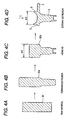
Fig. 4 is a drawing for describing a process for manufacturing the hub ring. -
Fig. 5 is a drawing taken in the direction of an arrow V inFig. 4D . -
Fig. 6 is a sectional view for describing a sideway extrusion form for obtaining the hub ring. -
Fig. 7 is a drawing for describing a process for manufacturing the outer ring. -
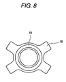
Fig. 8 is a drawing taken in the direction of an arrow VIII inFig. 7B . -
Fig. 9 is a sectional view for describing a sideway extrusion form for obtaining the outer ring. -
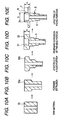
Fig. 10 is a process drawing for describing the method of manufacturing the bearing ring member of the wheel support hub unit in the second embodiment of the present invention. -
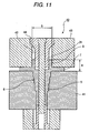
Fig. 11 is a sectional view showing an example of a upsetting form. -
Fig. 12 is a process drawing for describing the method of manufacturing the bearing ring member of the wheel support hub unit in the third embodiment of the present invention. -
Fig. 13 is a process drawing for describing the method of manufacturing the bearing ring member of the wheel support hub unit in the forth embodiment of the present invention. -
Fig. 14 is a drawing showing a bearing ring member having small-thickness portions among the fixing flanges, whereinFig. 14A is a drawing taken in the axial direction, andFig. 14B a sectional view taken along the line VI-VI inFig. 14A . -
Fig. 15 is a drawing showing a bearing ring member having heteromorphous fixing flanges, whereinFig. 15A is a drawing taken in the axial direction, andFig. 15B a sectional view taken along the line VII-VII inFig. 15A . -
Fig. 16 is a drawing for describing a related art method of manufacturing the bearing ring member shown inFig. 14 , whereinFig. 16A is a drawing taken in the axial direction, andFig. 16B a sectional view taken along the line VIII-VIII inFig. 16A . -
Fig. 17 is a drawing showing the removing of an excess thickness portion of the fixing flanges of the bearing ring member ofFig. 16 by a trimming process, whereinFig. 17A is a drawing taken in the axial direction, andFig. 17B a sectional view taken along the line IX-IX inFig. 17A . - An embodiment of the wheel support hub unit according to the present invention will now be described in detail with reference to the drawings.
- As shown in
Figs. 1 to 3 , a wheelsupport hub unit 1 is used as a driven wheel, and provided with a bearing unit having a hub (inner member) 2, an outer ring (outer member) 3 as a bearing ring member, and a plurality of rolling elements 4. - The
hub 2 is provided with ahub wheel 6 including asolid shaft portion 5 as a bearing ring member. Thehub wheel 6 is provided at an outboard-side end portion (outer end portion (left end portion inFig. 1 ) in the widthwise direction of the vehicle in a vehicle combined state) of the outer circumferential surface thereof withwheel fixing flanges 7 constituting the fixing portions extending in the radially outward direction which crosses theshaft portion 5 at right angles thereto. Thewheel fixing flanges 7 are provided on the outboard-side surface thereof with a plurality ofstuds 8 implanted therein at substantially equal intervals so as to fix a wheel, brake rotors and the like thereto. Each of thewheel fixing flange 7 is provided with fixingholes 7a, and formed so that thewheel fixing flanges 7 are not connected together in the positions of the pitch circles of thewheel fixing holes 7a. Thehub wheel 6 is provided at the outboard side of thewheel fixing flanges 7, i.e., at the opposite side of theshaft portion 5 via thewheel fixing flanges 7 with a wheel positioningcylindrical portion 9 projecting concentrically with theshaft portion 5. - The
hub wheel 6 is provided at an inboard side end portion (inside end portion in the vehicle widthwise direction in a vehicle-combined state, i.e., at the right end portion inFig. 1 ) with a small-diameter steppedportion 10, in which an inner race 11 is fitted. The inner race 11 is provided on an outer circumferential side thereof with aninner raceway surface 12, and on an outer circumferential side of an axially intermediate portion of thehub wheel 6 with aninner raceway surface 13. A front end at the inboard side of thehub wheel 6 is formed cylindrically, and the cylindrical portion (portion to be calked) 14 is calk-expanded radially outward. The inner race 11 is thereby calk-fixed to thehub wheel 6. The inner race 11 can be subjected to the application of necessary pre-pressurization by a nut (not shown) fastened to the inboard side end surface of thehub wheel 6 in addition to the calk-fixing techniques. - An
outer race 3 is formed so as to include ahollow shaft portion 15. The inner circumferential side of theouter race 3 is provided with anouter raceway surface 16 opposed to theinner raceway surface 13 of thehub wheel 6, and anouter raceway surface 17 opposed to aninner raceway surface 12 of the inner race 11. The end portion of theouter race 3 which is away from thewheel fixing flange 7 is provided with a plurality of suspensionunit fixing flanges 18, which constitute fixing portions extending in the direction crossing theshaft portion 15 at right angles thereto in a radially outward position. Each of the suspensionunit fixing flanges 18 is provided with a fixinghole 18a, and formed so that these flanges are not connected to one another in a pitch circle of these fixingholes 18a of the suspensionunit fixing flanges 18. Theouter ring 3 is provided at the inboard side of the suspensionunit fixing flanges 18 thereof, i.e., the portion thereof which is on the opposite side of theshaft portion 15 via thesuspension fixing flange 18 with a vehicle body positioningcylindrical portion 19 formed concentrically with theshaft portion 15. - A plurality of rolling elements 4 are arranged rollably in the circumferential direction via
retainers 20 between a plurality of rows of inner raceway surfaces 12, 13 and a plurality of outer raceway surfaces 16, 17. - In the illustrated example, balls are used as the rolling elements 4. In the case of a wheel support hub unit which has large weight, taper rollers are used sometimes as the rolling elements 4.
- In order to combine the above-described wheel
support hub unit 1 with an automobile, the suspensionunit fixing flanges 18 of theouter race 3 are fixed to the suspension unit, and a brake rotor and a wheel are secured to thewheel fixing flanges 7 of rotary ringside hub ring 6 viastuds 8 and nuts (not shown), etc. - This enables the wheel to be supported rotatably on the suspension unit.
- In the
hub wheel 6, thewheel fixing flanges 7 extending in the radial direction which is at right angles to theshaft portion 5 are formed by the cold side extrusion so that theseflanges 7 are integral with theshaft portion 5, and the positioningcylindrical portion 9 formed of the extrusion remaining portion occurring during the forming operation is also provided concentrically with theshaft portion 5 so that thecylindrical portion 9 is integral with theshaft portion 5. On the other hand, in theouter ring 3, the suspensionunit fixing flanges 18 extending in the radial direction which is at right angles to theshaft portion 15 are formed by the cold side extrusion so that the suspensionunit fixing flanges 18 are integral with theshaft portion 15, and the positioningcylindrical portion 19 formed by the extrusion remaining portion occurring during the forming operation is also provided concentrically with theshaft portion 15 so that thecylindrical portion 19 is integral with theshaft portion 15. The cold forging of thehub wheel 6 andouter race 3 will now be described. -
Figs. 4 to 6 show an example of a process for cold forging thehub ring 6. First, asolid rod material 30 ofFig. 4A is subjected to the forward extrusion forming to thereby form a shaft-like member 30a ofFig. 4B . A head portion of the shaft-like member 30a is then pressed by heading the same to an outer diameter substantially equal to that ΦD of the positioningcylindrical portion 9. As a result, ashaft portion element 30b shown inFig. 4C is formed. Thisshaft portion element 30b is further subjected to the side extrusion in the direction which is at right angles to the direction of the extrusion using aform 50 shown inFig. 6 . As a result, thehub ring 6 made integral of thewheel fixing flanges 7 and positioningcylindrical portion 9 is formed as shown inFigs. 4D and5 . In this embodiment, a solid shaft portion element is used. When a hollow shaft portion material is used, a hub ring for the driving wheel can be formed in the same manner. -
Fig. 6 shows aform 50 used in a side extrusion process for producing thehub ring 6, andFig. 6A the same form in a raw material inserted state,Fig. 6B showing the same form in a material forming state. Thisform 50 is provided with alower die 52 into which an inboard side end section of ashaft portion material 30b is inserted, and anupper die 51 urged toward the lower die by anelastic member 56. Theupper die 51 is provided with abore 57 the diameter of which is substantially equal to the outer diameter ΦD of the positioningcylindrical portion 9, and the outboard side end section (head section) of the shaft portionraw material 30b is provided in thebore 57. The part of the interior of thebore 57 which is on the upper side of the head section is provided with aring punch 55 and apunch 54 are so that these punches are slidable. Thering punch 55 and punch 54 are fixed to theupper form 58 to which theupper die 51 is fixed via theelastic member 56. Theradial grooves 53 may be formed in theupper die 51 or thelower die 52 alone. - When the
upper form 58 is then lowered, thepunch 54 forms a recess in an upper surface of the head section of the shaft portionraw material 30b and compresses the same in the axial direction to cause an outer circumferential portion of the head section of the shaft portionraw material 30b to be extruded into the radial grooves in the direction (sideways) which is at right angles to the direction in which the punch advances. Thewheel fixing flanges 7 are thereby formed so as to be integral with theshaft portion 5 with the extrusion remaining portion of the head section of ΦD which occurs during the forming operation becoming the positioningcylindrical portion 9. - During this time, the forming load is imparted to only the inner surface of the head section, and does not have influence on the length (surface area). Therefore, when the length (surface area) of the
wheel fixing flanges 7 is large, the flanges can be formed with a very small forming load as compared with that in the case where thewheel fixing flanges 7 are compression formed. - An example of a step of cold forging the
outer ring 3 will now be described with reference toFigs. 7 to 9 . In this example, a hollow cylindrical shaft portionraw material 40 ofFig. 7A (this shaft portion raw material can be obtained by removing the bottom by the draw forming or by removing the bottom by the rearward extrusion forming, and the like in addition to a seam welded pipe cutting method) is subjected to the side extrusion using a form shown inFig. 9 , in the direction which is at right angles to the pushing direction to thereby form an integral combination of the suspensionunit fixing flanges 18 and positioningcylindrical portion 19 as shown inFig. 7B and8 . A steppedportion 41 opposed to the outerring raceway surface 16 is then formed on the end portion inner surface on the outboard side as shown inFig. 7C to form theouter ring 3. -
Fig. 9 shows aform 70 used for a side extrusion process for obtaining theouter ring 3, whereinFig. 9A shows a raw material inserting state, andFig. 9B a forming state. Thisform 70 is provided with alower die 72 into which an end portion on the outboard side of ashaft portion element 40 is inserted, and anupper die 71 adapted to be urged toward thelower die 72 by anelastic member 76. Theupper die 71 is provided with abore 77 the diameter of which is substantially equal to an outer diameter ΦD0 of a positioningcylindrical portion 19, and an end portion of an inboard side of a shaft portionraw material 40 is placed in thebore 77. In the interior of the section of thebore 77 which is on the upper side of the end portion, aring punch 75 and apunch 74 are provided slidably, and these punches are fixed to theupper form 78 to which theupper die 71 is secured via theelastic member 76. At a front end portion of thepunch 74, amandrel 74a the diameter of which is substantially equal to an inner diameter ΦD1 of the shaft portionraw material 40 is provided so as to restrain the cylindrical shaft portionraw material 40. Between the end surfaces of theupper die 71 andlower die 72, radial grooves extending in the radially outward direction are provided. Theradial grooves 73 may be formed in theupper die 71 alone or in thelower die 72 alone. - When the
upper form 78 is lowered, thepunch 74 forms first a steppedportion 42, which is opposed to an outerring raceway surface 17, on an inner surface of an end portion on the shaft portionraw material 40. Thering punch 75 then contacts the inboard side end surface of the shaft portionraw material 40 and compresses the same in the axial direction (sideways). As a result, an outer circumferential portion of the shaft portionraw material 40 is extruded into theradial grooves 73 in the direction (sideways) which is at right angles to the direction in which the punch advances, and a suspensionunit fixing flanges 18 are formed in one body with theshaft portion 15, an extrusion remaining portion of the diameter ΦD0 occurring during the forming operation becoming a positioningcylindrical portion 19. - During this time, the forming load is imparted to the ring-shaped portion only of ΦD0 to ΦD1 of the shaft portion raw material, is not influenced by the length (surface area) of the suspension
unit fixing flanges 18. Therefore, the suspensionunit fixing flanges 18 having a large length (surface area) can be formed with an extremely small forming load as compared with the forming load in the case wheresuch flanges 18 are compression formed. In order to carry out the fluidization of the raw material in a well-balanced manner in theradial grooves 73, thelower die 72 may be made vertically movable just as theupper die 71, and may be urged toward theupper die 71 via an elastic member (upper and lower die-floating structure). - Therefore, in this embodiment, the
wheel fixing flanges 7 of thehub ring 6 are formed with thesolid shaft portion 5 in one body by the cold side extrusion, and the suspensionunit fixing flanges 18 of theouter ring 3 with thehollow shaft portion 15 in one body by the cold side extrusion. Therefore, even when the extrusion length (surface area) of thewheel fixing flanges 7 and suspensionunit fixing flanges 18 becomes large, the forming load does not vary owing to the features of the extrusion forming. This enables thewheel fixing flanges 7 and suspensionunit fixing flanges 18 to be formed with a low load by the cold forging using comparatively small equipment as compared withsuch flanges flange 7 and suspensionunit fixing flanges 18 compression formed. - The joint portion between the
wheel fixing flanges 7 and the outer circumferential portion of thehub ring 6 and the joint portion between the suspensionunit fixing flanges 18 and outer circumferential portion of theouter ring 3 are not subjected to a bending process. Therefore, a sufficient thickness of these joint portions can be secured, and thehub ring 6 andouter ring 3 of a sufficiently large strength can be obtained. - Since the
wheel fixing flanges 7 and suspensionunit fixing flanges 18 are sideway extrusion formed, the extrusion remaining portions can be used as the wheel positioningcylindrical portion 9 and vehicle body positioningcylindrical portion 19. This enables the circumferentially continuouscylindrical positioning portions shaft portions cylindrical portions - The present invention is not limited to the above-described embodiment, and suitable modifications without departing from the gist of the invention can be made.
- In this embodiment, the raceway ring member for the wheel support hub unit for the inner ring rotating driven wheel is shown. The present invention may, of course, be applied to the wheel support hub units for an inner ring rotating driving wheel, an outer ring rotating driven wheel, or an outer ring rotating driving wheel.
- In this embodiment, a plurality of rows of rolling bearings, around which the
outer ring 3 is fitted, are illustrated as the bearing portion thereof. The present invention may be applied to the raceway member of a wheel support hub unit employing a plurality of rows of rolling bearings the inner rings of which are divided at substantially an axially central portions thereof besides two rows of single-line angular ball bearings and two rows of single-line conical rolling bearings instead of the bearings illustrated above. - Further, the bearing ring member of a wheel support hub unit, and a method of manufacturing the same in each embodiment of the present invention will now be described in detail with reference to the drawings.
- The
hub ring 6 for a driving wheel, which is a bearing ring member of the wheelsupport hub unit 1 will be taken as an example, and a method of manufacturing the same will be described. First, as shown inFig. 10A , a hollow cylindrical shaft portionraw material 30 is subjected to forward extrusion forming to form ashaft portion member 30a ofFig. 10B . A head portion of theshaft portion member 30a member is then upset to form ashaft portion member 30b shown inFig. 10C . Thisshaft portion member 30b is subjected to a head portion rearward extrusion forming to form a head portion 132 having a steppedrecess 31 forming the shapes of the inner circumferences of theshaft portion 5 and positioningcylindrical portion 9. The head portion 132 is then upset so that that the height of thewheel fixing flanges 7 remains by using theform 40 shown inFig. 11 , to form thewheel fixing flanges 107. - The
form 40 is provided with alower die 41 having an inner circumferential surface the diameter of which is substantially equal to that of the outer circumferential surface of theshaft portion 5, anupper die 43 having abore 42 the diameter of which corresponds to that of an outer circumference D of the positioningcylindrical portion 9, and a radial deformation preventingguide member 44 engaged with theupper die 43 and engageable with the inner circumferential surface of the positioningcylindrical portion 9. When thehead portion 32 is upset so as to have the height of thewheel fixing flanges 7 remain by theupper die 43 with theshaft portion 5 of thewheel fixing flanges 7 held by thelower die 41, thewheel fixing flanges 7 are formed. - In this form, the
upper die 43 does not contact the part of the positioningcylindrical portion 9 which has a diameter smaller than that of the outer circumference D of the positioningcylindrical portion 9, and the outer part only of the positioningcylindrical portion 9 is upset. During such a upsetting operation, the height H of the head portion does not vary, so that the positioningcylindrical portion 9 is formed simultaneously with thewheel fixing flanges 7. Although the radial deformation preventingguide member 44 is fitted in the inner circumference of therecess 31 of the positioningcylindrical portion 9, the end surface of theguide member 44 is not brought into contact with a bottom surface of the positioningcylindrical portion 9. - The manufacturing method in this embodiment can also be applied when an outer ring and a hub ring for a driven wheel are manufactured.
- Therefore, in this embodiment, a
shaft portion 5 and arecess 31 are extrusion formed out of a hollow shaft portionraw material 30, and a head portion 132 is thereafter upset with the height of thewheel fixing flange 7 left thereon, by using theupper die 43 having abore 42 the diameter of which corresponds to the outer circumference of the positioningcylindrical portion 9. As a result, during the upset-forming of thewheel fixing flanges 7 in which the processing load is the highest, the part of the positioningcylindrical portion 9 which is on the inner side of the outer circumference thereof is not necessary to be compressed. Therefore, as compared with a case where thewheel fixing flanges 7 as a whole are upset, the surface area to be upset decreases, so that thewheel fixing flanges 7 can be formed with a low load. - This enables the
wheel fixing flanges 7 to be formed by the cold forging by using comparatively small equipment, and a cutting margin used in a later step decreases, so thatinexpensive hub ring 6 and wheelsupport hub unit 1 can be obtained. Since a joint portion between thewheel fixing flanges 7 and the outer circumferential section of theshaft portion 5 is not subjected to a bending process, a sufficient thickness can be secured in the joint portion, and thehub ring 106 and wheelsupport hub unit 1 which have a sufficient strength can be obtained. - During the upsetting process, the inner circumferential side of the
upper form 43 can be used to form the positioningcylindrical portion 9. Therefore, the circumferentially continuouscylindrical positioning portion 9 can be formed with theshaft portion 5 in one body easily with a high accuracy. Moreover, excess thickness for carrying out a necessary fixing operation becomes unnecessary when the positioningcylindrical portion 9 is formed separately, the material yield can be improved with the thickness of a necessary portion secured. This enables the manufacturing cost to be reduced. - A method of manufacturing a bearing ring member of a wheel support hub unit in a third embodiment of the present invention will now be described in detail with reference to
Fig. 12 with theouter ring 3 for the driving wheel in the second embodiment as a bearing ring member. - As shown in
Fig. 12A , a hollow cylindrical shaft portionraw material 50 is subjected to the forward extrusion forming to form ashaft portion member 50a having ahead portion 52 provided with arecess 51 forming an inner circumferential shape of ashaft portion 15 and positioning cylindrical portion Y19 ofFig. 12B . As shown inFig. 12C , a head portion 152 is then formed to a heteromorphous outer circumferential shape havingradial projections 53 the number of which is equal to that of fixingholes 118a provided in a suspensionunit fixing flanges 18. In the upsetting step ofFig. 12D , thehead portion 52 is then upset with theshaft portion 15 held in the lower die (not shown) and with thehead portion 52 left at the height of the suspensionunit fixing flanges 18 without restraining an outer circumference, by using an upper die (not shown) having a bore the diameter of which corresponds to the outer circumference D of the positioningcylindrical portion 19 to form the suspensionunit fixing flanges 18. - In this embodiment, the
head portion 52, i.e. an intermediate element in the heteromorphous upsetting step is heteromorphous, so that the suspensionunit fixing flanges 18 upset in the upsetting step is also heteromorphous with the upsetting surface area becoming required minimum. Therefore, a forming load becomes low, and the height H of thehead portion 52 does not vary, so that the positioningcylindrical portion 19 is formed at the same time. - In a stepped portion forming step (thinning step) shown in
Fig. 12E , interposed parts of circumferentially adjacent radial projections 142 are upset to smaller thickness to cause unnecessary parts of the suspensionunit fixing flanges 18 to be formed assmall thickness portions 54. As shown inFig. 12F , an excess thickness portion is then removed by trimming, and anouter ring 103 is thus manufactured. Since the upsetting operation in the stepped portion forming step is applied to thesmall thickness portions 54, and the other portions are not compressed, so that the forming load can be reduced. - The manufacturing method in this embodiment can also be applied when a hub ring for a driving wheel, and a hub ring for a driven wheel are manufactured.
- Accordingly, in this embodiment, the outer circumferential shape of the head portion 152 having the
radial projections 53 is set heteromorphous in the heteromorphous head portion forming step, so that the outer circumference of the suspensionunit fixing flanges 18 not yet upset can be set heteromorphous. As a result, the surface area of the portion to be upset decreases during the upsetting process enable the forming load to be held down to a low level. In order to upset the small thickness portions only of the suspensionunit fixing flanges 18, the forming load can be held down to a low level since the outer circumference can be reduced after the circumference is upset. Moreover, since the quantity of trimming of the outer circumference decreases, the yield can be improved. - The other operation and effect are identical with the corresponding operation and effect of the above-described second embodiment, so that the description thereof in the third embodiment will be omitted.
- A method of manufacturing a bearing ring member of a wheel support hub unit in a forth embodiment of the present invention will now be described in detail with reference to
Fig. 13 with a hub ring 6' for a driven wheel shown inFig. 14 taken as an example of a bearing ring member. - First, a solid shaft portion
raw material 60 shown inFig. 13A is subjected to extrusion forming to form ashaft portion member 60a shown inFig. 13B . A head portion of theshaft portion member 60a is then upset to form ashaft portion member 60b shown inFig. 13C . Theshaft portion member 60b is then subjected to a head portion rearward extrusion forming as shown inFig. 13D , to form arecess 61 which is to form an inner circumferential shape of a shaft portion 5' and positioning cylindrical portion 9'. When an inner circumference of a die (not shown) is set heteromorphous at the same time, thehead portion 62 is formed as the outer circumference thereof is swelled to a heteromorphous shape. Thus, an outer circumferential shape havingradial projections 63 the number of which is equal to that of fixingholes 7a' provided in wheel fixing flanges 7' is formed. Thehead portion 62 is then upset in accordance with a upsetting step ofFig. 13E with the height H of the wheel fixing flanges 7' left on thehead portion 62 without restraining an outer circumference thereof with the shaft portion 5' held in a lower die (not shown), by using an upper die (not shown) having a bore of a circumferential length corresponds to an outer circumference D of the positioning cylindrical portion 9', and the wheel fixing flanges 7' are thereby formed. - During this time, the wheel fixing flanges 7' upset in the upsetting step also becomes heteromorphous since the head portion of an intermediate material in the head portion rearward extrusion step has a heteromorphous shape. As a result, the upsetting surface area comes to be at a required minimum level, so that a forming load becomes low. Since the height H does not vary, the positioning cylindrical portion 9' is formed at the same time.
- In a stepped portion forming step (thinning step) shown in
Fig. 13F , the portions among the circumferentially adjacentradial projections 63 are upset, and the thickness of unnecessary portions of the wheel fixing flanges 7' is thereby set smaller. Excess thickness portions are then removed by carrying out a trimming process shown inFig. 13G to manufacture a hub ring 6'. The upsetting operation in the stepped portion forming step is applied to only the portions, which are to form smaller thickness portions, and the other portions are not compressed, so that the forming load can be lowered. When the unnecessary excess thickness portions are trimmed off in the trimming step, wheel fixing flanges 7' of different thickness and small thickness portions 22' are formed. - The manufacturing method in this embodiment can also be applied to cases where the outer ring and hub ring for a driving wheel are manufactured.
- Therefore, in this embodiment, a
head portion 62 having a shaft portion 5' and arecess 61 is formed in the head portion rearward extrusion step, in which the outer circumferential shape of the head portion 162 havingradial projections 63 is at the same time set heteromorphous. The outer circumferential shape of the wheel fixing flanges 7' not yet upset is thereby set heteromorphous, so that the surface area of the part to be upset during a upsetting process decreases, a forming load being thereby rendered able to be held down to a low level. During the thinning step for upsetting only the small thickness portions 22' with respect to the wheel fixing flanges 7', the forming load can be held down to a low level since the outer circumference of the same flanges upset can be reduced. Furthermore, since the quantity to be trimmed of the outer circumference decreases, the yield can be improved. - Concerning the other operation and effect of this embodiment are identical with the corresponding operation and effect of the second embodiment, so that giving a description thereof will be omitted.
- The present invention is not limited to these embodiments, but can be suitably modified within the scope of the present invention.
- In these embodiments, a plurality of rows of rolling bearings around an end portion of the
hub ring 6 for which theouter ring 103 is fitted are shown as examples of bearing portions. The present invention may also be suitably applied to a bearing ring member of a wheel support hub unit employing a plurality of rows of rolling bearings in which an inner ring is divided into two at a substantially axially intermediate portion thereof in addition to a bearing ring member having two rows of single-row angular ball bearings or two rows of single-row conical rolling bearings instead of the rolling bearings shown as examples in the embodiments. - In the embodiments of the present invention, a driving wheel member of a wheel support hub unit for an inner ring rotating driving wheel, and a driving wheel member of a wheel support hub unit for an inner ring rotating driven wheel are shown as examples. The present invention may, of course, be applied to a bearing ring member of a wheel support hub unit for an outer ring rotating driven wheel or an outer ring rotating driving wheel.
-
- A1...RAW MATERIAL
- A2...FORWARD EXTRUSION
- A3...HEADING
- A4...SIDEWAY EXTRUSION
-
- A1...RAW MATERIAL
- A2...SIDEWAY EXTRUSION
- A3...FORMATION OF STEPPED PORTIONS
-
- A1...RAW MATERIAL
- A2...FORWARD EXTRUSION
- A3...UPSETTING OF A HEAD PORTION
- A4...REARWARD EXTRUSION OF THE HEAD PORTION
- AS...UPSETTING OF FIXING PORTIONS
-
- A1...RAW MATERIAL
- A2...FORWARD EXTRUSION
- A3...HETEROMORPHOUS UPSETTING OF A HEAD PORTION
- A4...UPSETTING OF FIXING PORTIONS
- A5...FORMATION OF STEPPED PARTS ON THE FIXING PORTIONS
- A6... TRIMMING
-
- A1...RAW MATERIAL
- A2...FORWARD EXTRUSION
- A3...UPSETTING OF A HEAD PORTION
- A4...REARWARD EXTRUSION OF THE HEAD PORTION
- AS...UPSETTING OF FIXING PORTIONS
- A6...FORMATION STEPPED PORTIONS ON THE FIXING PORTIONS
- A7...TRIMMING
-
- A1...HOT FORGING
-
- A1...TRIMMING
Claims (1)
- A method of manufacturing a bearing ring member of a wheel support hub unit (1) including a plurality of wheel or vehicle body fixing portions (7) extending radially outward from a solid or hollow shaft portion (5), and a wheel or vehicle body positioning cylinder (9) provided concentrically with the shaft portion (5),
each of the fixing portions (7) being provided with fixing holes (7a)
wherein the method comprises
a placing step for placing a raw material(30), which is formed to a predetermined shape in advance, for the shaft portion (5) in a die (50) having grooves (53) extending radially outward,
a pressing step for pressing at normal temperature the parts of the raw material (30) for the shaft portion (5) which corresponds to one or both end sections of the shaft portion (5),
a flowing step for making the raw material (30) for the shaft portion (5) flow in the grooves (53) of the die (50),
so that the fixing portions (7) with the shaft portion (5) in one body by the side extrusion is formed,
characterized in that
the raw material (30) is formed in the die (50) having grooves (53) extending radially outward in a radiating shape so that the fixing portions (7) are not connected one another in the positions of the pitch circles of the fixing holes (7a).
Applications Claiming Priority (2)
| Application Number | Priority Date | Filing Date | Title |
|---|---|---|---|
| JP2004298585A JP4581615B2 (en) | 2004-10-13 | 2004-10-13 | Wheel supporting hub unit, raceway member of wheel supporting hub unit, and manufacturing method thereof |
| JP2004335534A JP4470705B2 (en) | 2004-11-19 | 2004-11-19 | Wheel supporting hub unit, raceway member of wheel supporting hub unit, and manufacturing method thereof |
Publications (3)
| Publication Number | Publication Date |
|---|---|
| EP1647418A2 EP1647418A2 (en) | 2006-04-19 |
| EP1647418A3 EP1647418A3 (en) | 2008-11-26 |
| EP1647418B1 true EP1647418B1 (en) | 2012-06-27 |
Family
ID=35601893
Family Applications (1)
| Application Number | Title | Priority Date | Filing Date |
|---|---|---|---|
| EP05021050A Expired - Lifetime EP1647418B1 (en) | 2004-10-13 | 2005-09-27 | Hub unit with wheel support and bearing ring, and method of manufacturing the hub unit |
Country Status (2)
| Country | Link |
|---|---|
| US (2) | US8402661B2 (en) |
| EP (1) | EP1647418B1 (en) |
Families Citing this family (19)
| Publication number | Priority date | Publication date | Assignee | Title |
|---|---|---|---|---|
| JP5040108B2 (en) * | 2005-12-08 | 2012-10-03 | 日本精工株式会社 | Manufacturing method of bearing ring member constituting rolling bearing unit for supporting wheel |
| JP5079270B2 (en) * | 2006-06-28 | 2012-11-21 | Ntn株式会社 | Wheel bearing unit |
| US8083598B2 (en) | 2006-07-11 | 2011-12-27 | Ntn Corporation | Bearing device for wheel |
| EP2599641B1 (en) * | 2006-08-07 | 2015-06-10 | NSK Ltd. | Bearing unit raceway ring member, bearing unit, and method and apparatus for manufacturing bearing unit raceway ring member |
| DE112008002291B4 (en) | 2007-10-02 | 2021-07-22 | Nsk Ltd. | Method for manufacturing a bearing ring member for a rolling bearing unit |
| EP2239069B1 (en) * | 2008-01-29 | 2016-11-23 | NSK Ltd. | Method for manufacturing outward-flanged metallic member |
| CN101804770B (en) * | 2009-02-17 | 2015-03-04 | 株式会社捷太格特 | Wheel bearing device and manufacturing method therefor |
| US20100210369A1 (en) | 2009-02-17 | 2010-08-19 | Jtekt Corporation | Wheel bearing device and manufacturing method therefor |
| JP2012183562A (en) * | 2011-03-07 | 2012-09-27 | Jtekt Corp | Method of manufacturing shaft member for wheel rolling bearing device |
| JP2012197070A (en) | 2011-03-07 | 2012-10-18 | Jtekt Corp | Manufacturing method for wheel rolling bearing device, and wheel rolling bearing device |
| DE102011005326A1 (en) * | 2011-03-10 | 2012-09-13 | Schaeffler Technologies Gmbh & Co. Kg | Method for producing a bearing ring, in particular for a tapered roller bearing |
| JP2013147052A (en) | 2012-01-17 | 2013-08-01 | Jtekt Corp | Wheel rolling bearing device |
| JP2013180675A (en) * | 2012-03-02 | 2013-09-12 | Jtekt Corp | Wheel support device |
| US9751124B2 (en) * | 2013-01-29 | 2017-09-05 | Arvinmeritor Technology, Llc | System and method of making a forged part |
| JP6237273B2 (en) * | 2014-01-30 | 2017-11-29 | 株式会社ジェイテクト | Joint member for wind power generator and wind power generator |
| USD845842S1 (en) * | 2017-08-13 | 2019-04-16 | Mike Sun | Automotive spindle |
| JP1601194S (en) * | 2017-10-12 | 2018-04-09 | ||
| IT201900023205A1 (en) * | 2019-12-06 | 2021-06-06 | Skf Ab | SUSPENSION ASSEMBLY FOR VEHICLES, INCLUDING A WHEEL HUB UNIT AND A SUSPENSION POST OR JOINT |
| EP3974679B1 (en) * | 2020-09-28 | 2024-05-01 | Cie Automotive, S.A. | Mechanical actuator |
Family Cites Families (19)
| Publication number | Priority date | Publication date | Assignee | Title |
|---|---|---|---|---|
| NL164807C (en) * | 1970-02-05 | 1981-02-16 | Skf Svenska Kullagerfab Ab | VEHICLE WITH DRIVEN AND NON-DRIVEN WHEELS, EQUIPPED WITH THE SAME BEARING UNIT. |
| DE2233966A1 (en) * | 1972-07-11 | 1974-01-31 | Schuerhoff & Co Gmbh | METHOD AND TOOL FOR MANUFACTURING THE HUB BODY OF A BRAKABLE FREE WHEEL FOR SINGLE-TRACKED VEHICLES SUCH AS BICYCLES, MOTORCYCLES OR THE LIKE. FROM A CYLINDRICAL PIPE WALL DUE TO A PLASTIC DEFORMATION |
| DE2242531A1 (en) * | 1972-08-30 | 1974-03-07 | Schuerhoff & Co Gmbh | METHOD FOR MANUFACTURING HUBS FOR BICYCLES OR THE LIKE |
| JPS61195726A (en) | 1985-02-26 | 1986-08-30 | Tokai Rika Co Ltd | Manufacture of cylinder member with flange |
| EP0356589A1 (en) * | 1988-09-01 | 1990-03-07 | Lai, Ta-chi | Construction of bicycle hub |
| JP2535223B2 (en) | 1989-05-16 | 1996-09-18 | 株式会社小松製作所 | Molding method for parts having deformed flanges |
| CN1040185C (en) | 1994-10-14 | 1998-10-14 | 谢钦河 | A kind of manufacturing method of flower hub |
| JP3572826B2 (en) | 1996-10-18 | 2004-10-06 | 日立電線株式会社 | Manufacturing method of bracket with bracket |
| US6157820A (en) | 1998-06-12 | 2000-12-05 | Ericsson Inc. | Pilot strength measurement and multipath delay searcher for CDMA receiver |
| JP4193344B2 (en) | 2000-08-22 | 2008-12-10 | 日本精工株式会社 | Wheel drive unit |
| JP4724970B2 (en) | 2001-07-19 | 2011-07-13 | 株式会社ジェイテクト | Axle bearing device |
| US6772615B2 (en) * | 2001-09-20 | 2004-08-10 | Nsk Ltd. | Method of manufacturing hub unit for supporting wheel and die for manufacturing the same |
| DE10202200B4 (en) * | 2002-01-22 | 2013-05-16 | Schaeffler Technologies AG & Co. KG | Wheel bearing unit with mounting holes for the brake caliper bracket |
| JP4013618B2 (en) | 2002-04-02 | 2007-11-28 | 株式会社ジェイテクト | Rolling bearing device |
| JP4085736B2 (en) | 2002-08-09 | 2008-05-14 | 株式会社ジェイテクト | Rolling bearing device |
| JP4244631B2 (en) * | 2002-12-20 | 2009-03-25 | 株式会社ジェイテクト | Rolling bearing device |
| JP2004203209A (en) | 2002-12-25 | 2004-07-22 | Ntn Corp | Wheel bearing |
| DE10331180A1 (en) * | 2003-07-10 | 2005-02-24 | Fag Kugelfischer Ag & Co. Ohg | Bearing ring and wheel bearing unit |
| US7470067B2 (en) * | 2004-12-20 | 2008-12-30 | Kyklos Bearing International, Inc. | Wheel bearing assembly mount with force attenuation |
-
2005
- 2005-09-27 EP EP05021050A patent/EP1647418B1/en not_active Expired - Lifetime
- 2005-09-30 US US11/239,314 patent/US8402661B2/en active Active
-
2013
- 2013-02-26 US US13/777,263 patent/US8881405B2/en not_active Expired - Lifetime
Also Published As
| Publication number | Publication date |
|---|---|
| EP1647418A3 (en) | 2008-11-26 |
| US8402661B2 (en) | 2013-03-26 |
| US20130167611A1 (en) | 2013-07-04 |
| US8881405B2 (en) | 2014-11-11 |
| US20060117903A1 (en) | 2006-06-08 |
| EP1647418A2 (en) | 2006-04-19 |
Similar Documents
| Publication | Publication Date | Title |
|---|---|---|
| US8881405B2 (en) | Wheel support hub unit, bearing ring member for wheel support hub unit, and method of manufacturing the same | |
| CN1760052B (en) | Wheel supporting hub unit, bearing ring element thereof, and manufacturing method thereof | |
| JP4724970B2 (en) | Axle bearing device | |
| EP2599640B1 (en) | Bearing unit and method for producing a raceway ring member for a bearing unit | |
| EP2123374B1 (en) | Method for manufacturing raceway ring member | |
| JP4470705B2 (en) | Wheel supporting hub unit, raceway member of wheel supporting hub unit, and manufacturing method thereof | |
| EP1110756B1 (en) | Wheel-support rolling bearing unit and a method manufacturing the same | |
| WO2016098886A1 (en) | Method for manufacturing inner member and hub ring of wheel bearing device | |
| US8516705B2 (en) | Method of manufacturing bearing ring member for rolling bearing unit | |
| JP5061552B2 (en) | Method for manufacturing hub unit for driving wheel support | |
| CN101309804A (en) | Complete bearing assembly and assembly method thereof | |
| JP4752420B2 (en) | Rolling bearing device and manufacturing method thereof | |
| JP4840102B2 (en) | Method for manufacturing bearing ring member | |
| JP4674580B2 (en) | Method for manufacturing bearing ring member | |
| JP2007016959A (en) | Manufacturing method of outer ring of rolling bearing unit for wheel support | |
| JP4239542B2 (en) | Rolling bearing device | |
| JP5168852B2 (en) | Bearing unit | |
| JP2008188612A (en) | Method for manufacturing bearing ring member | |
| JP4848673B2 (en) | Manufacturing method of driven wheel hub unit | |
| JP2026075114A (en) | Crimping joint method, method for manufacturing hub unit bearings, method for manufacturing vehicles, method for manufacturing mechanical equipment, and crimping apparatus | |
| JP2005280513A (en) | Method of manufacturing bearing ring member for hub unit | |
| JP2010241381A (en) | Manufacturing method of inner diameter raceway member constituting rolling bearing unit for supporting wheel | |
| JP2008064261A (en) | Manufacturing method of outer ring of rolling bearing unit for wheel support | |
| JP2009255130A (en) | Method and apparatus for plastic working of metal-made member | |
| JP2007218276A (en) | Driving wheel bearing device |
Legal Events
| Date | Code | Title | Description |
|---|---|---|---|
| PUAI | Public reference made under article 153(3) epc to a published international application that has entered the european phase |
Free format text: ORIGINAL CODE: 0009012 |
|
| AK | Designated contracting states |
Kind code of ref document: A2 Designated state(s): AT BE BG CH CY CZ DE DK EE ES FI FR GB GR HU IE IS IT LI LT LU LV MC NL PL PT RO SE SI SK TR |
|
| AX | Request for extension of the european patent |
Extension state: AL BA HR MK YU |
|
| PUAL | Search report despatched |
Free format text: ORIGINAL CODE: 0009013 |
|
| AK | Designated contracting states |
Kind code of ref document: A3 Designated state(s): AT BE BG CH CY CZ DE DK EE ES FI FR GB GR HU IE IS IT LI LT LU LV MC NL PL PT RO SE SI SK TR |
|
| AX | Request for extension of the european patent |
Extension state: AL BA HR MK YU |
|
| 17P | Request for examination filed |
Effective date: 20090515 |
|
| 17Q | First examination report despatched |
Effective date: 20090624 |
|
| AKX | Designation fees paid |
Designated state(s): DE |
|
| GRAP | Despatch of communication of intention to grant a patent |
Free format text: ORIGINAL CODE: EPIDOSNIGR1 |
|
| RIC1 | Information provided on ipc code assigned before grant |
Ipc: B60B 27/00 20060101AFI20111221BHEP Ipc: B21K 1/40 20060101ALI20111221BHEP Ipc: F16C 33/64 20060101ALI20111221BHEP Ipc: F16C 19/18 20060101ALI20111221BHEP |
|
| GRAS | Grant fee paid |
Free format text: ORIGINAL CODE: EPIDOSNIGR3 |
|
| GRAA | (expected) grant |
Free format text: ORIGINAL CODE: 0009210 |
|
| AK | Designated contracting states |
Kind code of ref document: B1 Designated state(s): DE |
|
| REG | Reference to a national code |
Ref country code: DE Ref legal event code: R096 Ref document number: 602005034911 Country of ref document: DE Effective date: 20120823 |
|
| PLBE | No opposition filed within time limit |
Free format text: ORIGINAL CODE: 0009261 |
|
| STAA | Information on the status of an ep patent application or granted ep patent |
Free format text: STATUS: NO OPPOSITION FILED WITHIN TIME LIMIT |
|
| 26N | No opposition filed |
Effective date: 20130328 |
|
| REG | Reference to a national code |
Ref country code: DE Ref legal event code: R097 Ref document number: 602005034911 Country of ref document: DE Effective date: 20130328 |
|
| PGFP | Annual fee paid to national office [announced via postgrant information from national office to epo] |
Ref country code: DE Payment date: 20240730 Year of fee payment: 20 |
|
| REG | Reference to a national code |
Ref country code: DE Ref legal event code: R071 Ref document number: 602005034911 Country of ref document: DE |