EP1647394A1 - Method and apparatus for producing an article by winding a rubber strip on a supporting body - Google Patents
Method and apparatus for producing an article by winding a rubber strip on a supporting body Download PDFInfo
- Publication number
- EP1647394A1 EP1647394A1 EP05021888A EP05021888A EP1647394A1 EP 1647394 A1 EP1647394 A1 EP 1647394A1 EP 05021888 A EP05021888 A EP 05021888A EP 05021888 A EP05021888 A EP 05021888A EP 1647394 A1 EP1647394 A1 EP 1647394A1
- Authority
- EP
- European Patent Office
- Prior art keywords
- sending
- out roller
- rubber strip
- cylindrical body
- axis
- Prior art date
- Legal status (The legal status is an assumption and is not a legal conclusion. Google has not performed a legal analysis and makes no representation as to the accuracy of the status listed.)
- Granted
Links
- 238000004804 winding Methods 0.000 title claims abstract description 79
- 238000000034 method Methods 0.000 title claims description 17
- 230000002093 peripheral effect Effects 0.000 claims abstract description 10
- 230000007547 defect Effects 0.000 description 9
- IUVCFHHAEHNCFT-INIZCTEOSA-N 2-[(1s)-1-[4-amino-3-(3-fluoro-4-propan-2-yloxyphenyl)pyrazolo[3,4-d]pyrimidin-1-yl]ethyl]-6-fluoro-3-(3-fluorophenyl)chromen-4-one Chemical compound C1=C(F)C(OC(C)C)=CC=C1C(C1=C(N)N=CN=C11)=NN1[C@@H](C)C1=C(C=2C=C(F)C=CC=2)C(=O)C2=CC(F)=CC=C2O1 IUVCFHHAEHNCFT-INIZCTEOSA-N 0.000 description 2
- 238000012937 correction Methods 0.000 description 2
- 230000000694 effects Effects 0.000 description 2
- 230000002708 enhancing effect Effects 0.000 description 2
- 239000000463 material Substances 0.000 description 2
- 230000002411 adverse Effects 0.000 description 1
- 238000013459 approach Methods 0.000 description 1
- 230000008602 contraction Effects 0.000 description 1
- 238000007796 conventional method Methods 0.000 description 1
- 238000010586 diagram Methods 0.000 description 1
- 238000011156 evaluation Methods 0.000 description 1
- 238000012886 linear function Methods 0.000 description 1
- 239000000203 mixture Substances 0.000 description 1
- 230000003014 reinforcing effect Effects 0.000 description 1
Images



Classifications
-
- B—PERFORMING OPERATIONS; TRANSPORTING
- B29—WORKING OF PLASTICS; WORKING OF SUBSTANCES IN A PLASTIC STATE IN GENERAL
- B29D—PRODUCING PARTICULAR ARTICLES FROM PLASTICS OR FROM SUBSTANCES IN A PLASTIC STATE
- B29D30/00—Producing pneumatic or solid tyres or parts thereof
- B29D30/06—Pneumatic tyres or parts thereof (e.g. produced by casting, moulding, compression moulding, injection moulding, centrifugal casting)
- B29D30/52—Unvulcanised treads, e.g. on used tyres; Retreading
- B29D30/58—Applying bands of rubber treads, i.e. applying camel backs
- B29D30/60—Applying bands of rubber treads, i.e. applying camel backs by winding narrow strips
-
- B—PERFORMING OPERATIONS; TRANSPORTING
- B29—WORKING OF PLASTICS; WORKING OF SUBSTANCES IN A PLASTIC STATE IN GENERAL
- B29D—PRODUCING PARTICULAR ARTICLES FROM PLASTICS OR FROM SUBSTANCES IN A PLASTIC STATE
- B29D30/00—Producing pneumatic or solid tyres or parts thereof
- B29D30/06—Pneumatic tyres or parts thereof (e.g. produced by casting, moulding, compression moulding, injection moulding, centrifugal casting)
- B29D30/08—Building tyres
- B29D30/20—Building tyres by the flat-tyre method, i.e. building on cylindrical drums
- B29D30/30—Applying the layers; Guiding or stretching the layers during application
Definitions
- the present invention relates to a producing method of a rubber strip winding body, and a rubber strip winding apparatus capable of enhancing precision and quality of a winding body formed by spirally winding a rubber strip around a cylindrical body.
- a pneumatic tire As a pneumatic tire is required to show different characteristics depending on the part, it is composed of various rubber members such as a tread rubber, a sidewall rubber, a clinch rubber, a breaker cushion rubber, an inner liner rubber and the like having different compositions and cross sections.
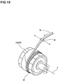
- a strip wind type As roughly shown in Fig. 10, when an unvulcanized rubber strip (b) is supplied to an outer peripheral surface (cs) of a cylindrical body (c) from a sending-out roller (a), the sending-out roller (a) is laterally moved in the axial direction of the cylindrical body (c) as the cylindrical body (c) rotates. With this, a winding body (d) in which the rubber strip (b) is partially overlapped and spirally wound is formed.
- the cylindrical body (c) includes a former for forming a tire, and a tire member formed on such former.
- sending-out roller (a) is laterally moved in the axial direction (i) of the cylindrical body (c) while an axis of the sending-out roller (a) is held in parallel to the axis of the cylindrical body (c).
- the rubber strip (b) is partially overlapped and is pasted in succession at an angle with respect to the axial direction (i).
- a torsion (k) between the sending-out roller (a) and the cylindrical body (c) is applied to the rubber strip (b), and with this, the rubber strip (b) is pasted with a moving amount smaller than a moving amount of the sending-out roller (a).
- a deviation between a position of the actually pasted rubber strip (b) and a position of the sending-out roller (a) is increased.
- the rubber strip is largely deviated laterally, and catches up the position of the sending-out roller (a).
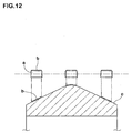
- the strip wind method may be used in forming a tread rubber for an automatic two-wheeled vehicle, and in such a case, as shown in Fig. 12, a drum whose diameter is large in the central portion as compared to the end portions is used as the cylindrical body (c) .
- a drum whose diameter is large in the central portion as compared to the end portions is used as the cylindrical body (c) .
- an invention described in claim 1 is a producing method of a rubber strip winding body in which an unvulcanized rubber strip (3) is supplied to an outer peripheral surface of a rotating cylindrical body (4) from a sending-out roller (16) which laterally moves in an axial direction of the cylindrical body (4) , thereby spirally winding the rubber strip (3) to form a winding body (5), characterized in that in a tilting reference plane (29) defined as a plane which is in parallel to a plane (4S) passing through an axis (4i) of the cylindrical body (4) and which passes through an axis (16i) of the sending-out roller (16), the sending-out roller (16) is held such that the sending-out roller (16) can tilt positively and negatively within an inclination angle ( ⁇ ) of 0 to 45° with respect to a tilting reference line (N) which passes through a bisector point (No) on the axis (16i) which bisects a length of the sending-out roller (16) and which is parallel to the axis
- An invention described in claim 2 is a rubber strip winding apparatus in which an unvulcanized rubber strip (3) is supplied to an outer peripheral surface of a rotating cylindrical body (4) from a sending-out roller (16) which laterally moves in an axial direction of the cylindrical body (4), thereby spirally winding the rubber strip (3) to form a winding body (5), characterized in that the rubber strip winding apparatus comprises an applicator (17) having the sending-out roller (16), the applicator (17) comprises laterally moving means (21) which laterally moves the sending-out roller (16) along an X-axis direction which is parallel to the axis (4i) of the cylindrical body (4), vertically moving means (22) which forwardly and backwardly moves the sending-out roller (16) toward the cylindrical body (4) along a Z-axis direction which intersects with the X-axis direction at right angles, and tilting means (23) for tilting the sending-out roller (16) positively and negatively within an inclination angle ( ⁇ ) with respect to a tilting reference line (N) which extends in the
- the present invention has the above-described structure, it is possible to suppress torsion of the rubber strip, to enhance the winding precision, and to form a high quality and high precision winding body having a cross section closer to the target stably .
- Fig. 1 is a schematic side view of a rubber strip winding apparatus of the present invention.
- Fig. 2 is an enlarged side view of an applicator of the winding apparatus.
- Fig. 3 is a perspective view of the applicator.
- the rubber strip winding apparatus 1 of the embodiment is disposed between a rubber extruding machine 11 and a forming apparatus 13 which rotatably supports a cylindrical body 4.
- An unvulcanized tape-like rubber strip 3 extruded from the rubber extruding machine 11 is spirally wound on an outer peripheral surface S of the cylindrical body 4, thereby forming a winding body 5.
- the cylindrical body 4 comprises a straight cylindrical former 6 for forming a tire tread, and a tread reinforcing layer 7 such as a belt layer formed on the former 6.
- the winding body 5 for tread rubber which is a tire rubber member is formed on an outer surface S of the cylindrical body 4.
- the winding apparatus 1 includes an inexpansible conveyer tape J which is guided by a plurality of rollers R such that the conveyer tape J can run around.
- the rubber strip 3 is adhered to and held on one surface of the conveyer tape J and is conveyed. More concretely, the winding apparatus 1 comprises
- the loader 14 includes a loading roller Ra which can be displaced by expansion and contraction of the cylinder 18 such that the loading roller Ra can approach and separate from a lower calender roll 11a of the rubber extruding machine 11.
- the loading roller Ra abuts, the tip end of the rubber strip 3 which is adhered to the lower calender roll 11a is loaded to the conveyer tape J.
- the accumulator 15 includes a forward-sending path accumulator 15A in which the conveyer tape J runs from the rubber extruding machine toward the forming apparatus, and a backward-sending path accumulator 15B in which the conveyer tape J returns from the forming apparatus.
- the forward-sending path accumulator 15A includes upper rollers R1U of the forward-sending path arranged in one lateral row at upper positions, and lower rollers R1L of the forward-sending path arranged in one lateral row below the upper rollers R1U, and the conveyer tape J runs in a zigzag form while being folded back between the upper and lower rollers RIU and RIL.
- the backward-sending path accumulator 15B includes upper rollers R2U of the backward-sending path arranged in one lateral row at upper positions, and lower rollers R2L of the backward-sending path arranged in one lateral row below the upper rollers R2U, and the conveyer tape J runs in a zigzag form while being folded back between the upper and lower rollers R2U and R2L.
- the upper rollers R1U and R2U of the forward-sending path and backward-sending path are pivotally supported by fixed frames 19A and 19B, and the lower rollers R1L and R2L of the forward-sending path and backward-sending path are pivotally supported by vertically moving frames 19C and 19D which can move vertically.
- the winding apparatus 1 includes a first motor M1 which continuously drives the conveyer tape J in synchronism with the rubber extruding machine 11, and a second motor M2 which intermittently drives the conveyer tape J in synchronism with the former 6.
- a first motor M1 which continuously drives the conveyer tape J in synchronism with the rubber extruding machine 11
- a second motor M2 which intermittently drives the conveyer tape J in synchronism with the former 6.
- the conveyer tape J having the rubber strip accumulated in the forward-sending path accumulator 15A is taken out by the rotation of the driving rollers by the second motor M2, and the rubber strip 3 is supplied to the cylindrical body 4 from the sending-out roller 16.
- the applicator 17 includes
- the laterally moving means (21) includes a lateral guide rail 21A laid in the X-axis direction, and a laterally moving stage 21B guided by the lateral guide rail 21A and can be moved laterally.
- the laterally moving stage 21B is connected to a motor (not shown) through driving force transmitting means of a known structure such as a ball screw mechanism, a gear connecting mechanism and a belt connecting mechanism.
- the vertically moving stage 21B can move forwardly and backwardly at required speed through a required distance by controlling the rotation of the motor.
- the vertically moving means 22 includes a vertical guide rail 22A which is laid on the laterally moving stage 21B and which extends in the Z-axis direction, and a vertically moving stage 22B which is guided by the vertical guide rail 22A and can move forwardly and backwardly toward the former 6.
- the vertically moving stage 22B is also connected to a motor (not shown) through driving force transmitting means of a known structure such as a ball screw mechanism, a gear connecting mechanism and a belt connecting mechanism.
- the vertically moving stage 22B can forwardly and backwardly move at required speed through a required distance by controlling the rotation of the motor.
- the tilting means 23 includes a support shaft 23A which stands on the vertically moving stage 22B, and a tiltable stage 23B supported by the support shaft 23A.
- the support shaft 23A is pivotally attached to the tiltable stage 23B such that the tiltable stage 23B can tilt around the reference axis zi which is an axis 23i of the support shaft 23A.
- a drive motor (not shown) is connected to the tiltable stage 23B, the motor rotates at any speed around the reference axis zi, and the rotation angle thereof is detected and controlled by an angle sensor such as an encoder.
- the laterally moving means 21 and the vertically moving means 22 may be exchanged.
- the laterally moving stage 21B can be disposed on the vertically moving stage 22B such that the laterally moving stage 21B can laterally move, and the tiltable stage 23B can be pivotally attached to the laterally moving stage 21B such that the tiltable stage 23B can tilt.
- a table-like frame 26 stands on the tiltable stage 23B, and a strip guide 25 on which the plurality of rollers R including the sending-out roller 16 is formed on the tiltable stage 23B.
- the rollers R are pivotally attached to a long plate-like support arm 27 mounted on the frame 26.
- the roller R at least includes the sending-out roller 16 disposed on a front end of the support arm 27, and a large-diameter drive roller 28 which drives the conveyer tape J in synchronism with the rotation of the former 6 in association with the second motor M2.
- a plane 16S which is in parallel to a plane 4S which passes through an axis i of the cylindrical body 4 and passing through an axis 16i of the sending-out roller 16 is defined as a tilting reference plane 29, and the sending-out roller 16 is held within the tilting reference plane 29 such that the sending-out roller 16 can tilt. More specifically, the axis 16i of the sending-out roller 16 is disposed in the tilting reference plane 29 which is perpendicular to the Z-axis direction. At that time, in this embodiment, the plane 4S is formed such that the rubber strip 3 from the sending-out roller 16 passes through a contact position Q which is in contact with the cylindrical body 4.
- the sending-out roller 16 is held such that it can tilt positively and negatively with respect to a tilting reference line N on the tilting reference plane 29 at an inclination angle ⁇ of 0 to 45°.
- the "tilting reference line N" means a straight line which passes through a point (bisector point) No on the axis 16i which bisects a length of the sending-out roller 16 and extends in the X-axis direction.
- This embodiment shows a case in which the plane 4S and the tilting reference plane 29 are different surfaces.
- the tilting reference plane 29 may pass through the axis i of the cylindrical body 4, i.e., the tilting reference plane 29 and the plane 4S may be the same surface.
- This embodiment shows a case in which the reference axis zi passes through the bisector point No. This can facilitate the control of the tilting motion of the sending-out roller 16. If the reference axis zi does not pass through the bisector point No, as shown in Fig. 5, errors x and y in the X-axis direction and Y-axis direction are generated at the position of the bisector point No by the tilting motion, it becomes necessary to always correct the errors by the laterally moving means 21 and the vertically moving means 22 and thus, this complicates the control. Thus, in this embodiment, the tilting motion is carried out around the reference axis zi in the vertical Z-axis direction. Thus, the load applied in the reference axis zi can be reduced, precision and smoothness of the tilting operation can be enhanced, and the durability of the apparatus can be enhanced.
- the applicator 17 further comprises control means (30) which controls the laterally moving means (21), the vertically moving means (22) and the tilting means (23).
- the control means 30 changes the inclination angle ⁇ of the sending-out roller 16 in accordance with the inclination of a wound and overlapped surface 5AS of the winding body portion 5A. That is, the control means 30 laterally moves the sending-out roller 16, and changes the inclination angle ⁇ of the sending-out roller 16 in accordance with an inclination angle ⁇ C with respect to the X-axis direction of the wound and overlapped surface 5AS.
- a lateral moving amount of the sending-out roller 16 of one turn of the cylindrical body 4 is stored, and the inclination angle ⁇ , of the sending-out roller 16 is controlled whenever the cylindrical body 4 rotates once. If the outer surface of the cylindrical body 4 is of substantially straight cylindrical shape as in this embodiment, it is preferable that the bisector point No of the sending-out roller 16 laterally moves through one running line L extending in the X-axis direction.
- an angle ⁇ of the contact position Q with respect to the plane 4S is set to 60° or less, and more preferably 30° or less. There is a tendency that as the angle ⁇ becomes greater, the above-described effect is more deteriorated. Thus, it is most preferable that the plane 4S is disposed at a position ( ⁇ ⁇ 0°) passing through the contact position Q.
- the upper limit of the inclination angle ⁇ of the sending-out roller 16 is 45°. If the inclination angle ⁇ exceeds 45°, there is an adverse possibility that slippage of the rubber strip 3 on the sending-out roller 16 and the positional deviation of the rubber strip 3 is generated, the deformation of the rubber strip 3 is increased, and a high quality and high precision winding body 5 having a cross section close to the target can not be obtained. Thus, it is preferable that the upper limit of the inclination angle ⁇ is 40° or less.
- the inclination angle ⁇ of the sending-out roller is changed in accordance with the inclination angle ⁇ C of the wound and overlapped surface 5AS.
- this function various functions other than a linear function can also be employed.
- Figs. 7 and 8 show a case in which a winding body 5 for a tread rubber of a tire for an automatic two-wheeled vehicle is formed using the applicator 17.
- the cylindrical body 4 has a drum-like contour shape whose central portion has a larger diameter than those of the end portions of the drum.
- the laterally moving means (21), the vertically moving means 22 and the tilting means 23 are controlled by the control means 30.
- the inclination angle ⁇ of the sending-out roller 16 is changed in accordance with the contour line of the cylindrical body 4 while laterally moving the sending-out roller 16.
- the sending-out roller 16 laterally moves such that the bisector point No of the sending-out roller 16 passes on the one running line L which is parallel to the contour line of the cylindrical body 4.
- the distance between the sending-out roller 16 and the cylindrical body 4 becomes constant, and the torsion of the rubber strip 3 can further be suppressed.
- the sending-out roller 16 may be laterally moved such that the bisector point No passes on one running line L which is parallel to the axis 4i of the cylindrical body 4.
- the tilting reference plane 29 and the plane 4S are the same surface, but the tilting reference plane 29 and the plane 4S may be different two surfaces.
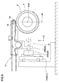
- Fig. 9 shows another example of the applicator 17.
- the applicator 17 support the vertically moving stage 22B of the vertically moving means 22 such that the vertically moving stage 22B can forwardly and backwardly move, and in this example, the Y-axis direction is a vertical direction.
- the Z-axis direction is directed to a longitudinal direction, and the tiltable stage 23B of the tilting means 23 is supported such that the tiltable stage 23B can tilt around the horizontal reference axis zi.
- the axis 16i of the sending-out roller 16 is disposed on the tilting reference plane 29 which is perpendicular to the horizontal Z-axis direction.
- the sending-out roller 16 can laterally move within the vertical reference plane 29 while changing the inclination angle ⁇ .
- the winding body of the rubber strip is not limited to the rubber material for a tire, and the winding body can also be applied to rubber materials of various purposes.
- a rubber strip was spirally wound on a former whose belt layer was previously formed in accordance with the specification shown in Table 1, to form a winding body for a tread rubber for a four-wheel vehicle tire.
- radial tires for a passenger vehicle having tire size of 215/45ZR17 were prototyped, and a generation status of defects on an outer surface and a uniformity of the tires were compared and evaluated.
- the former is of a straight cylindrical shape.
- the sending-out roller 16 laterally moves such that its bisector point No passes through a running line (straight line) which is parallel to the axis 4i of the former.
- winding body for a tread rubber of a tire for an automatic two-wheeled vehicle was formed in accordance with the specification shown in Table 2.
- tires for an automatic two-wheeled vehicle having tire size of 190/55R17 were prototyped, and a generation status of defects on an outer surface and a uniformity of the tires were compared and evaluated.
- the former has a drum-like contour shape, and a difference of a diameter DC at its central portion and a diameter Ds at its each of opposite ends was 120mm, and a width of the former was 185mm.
- a bisector point No thereof laterally moves through a running line (straight line) which is in parallel to the axis 4i of the former.
- a bisector point No of the sending-out roller 16 laterally moves through a running line (convex curve) which is in parallel to a contour line of the former.
Landscapes
- Engineering & Computer Science (AREA)
- Mechanical Engineering (AREA)
- Tyre Moulding (AREA)
Abstract
Description
- The present invention relates to a producing method of a rubber strip winding body, and a rubber strip winding apparatus capable of enhancing precision and quality of a winding body formed by spirally winding a rubber strip around a cylindrical body.
- As a pneumatic tire is required to show different characteristics depending on the part, it is composed of various rubber members such as a tread rubber, a sidewall rubber, a clinch rubber, a breaker cushion rubber, an inner liner rubber and the like having different compositions and cross sections.
- In recent years, it is proposed to form various kinds of tire rubber members that are formed by winding the rubber strip spirally using a so-called strip wind method. See Japanese Patent Application Laid-open No.2000-94542.
- In the case of this strip wind type, as roughly shown in Fig. 10, when an unvulcanized rubber strip (b) is supplied to an outer peripheral surface (cs) of a cylindrical body (c) from a sending-out roller (a), the sending-out roller (a) is laterally moved in the axial direction of the cylindrical body (c) as the cylindrical body (c) rotates. With this, a winding body (d) in which the rubber strip (b) is partially overlapped and spirally wound is formed. The cylindrical body (c) includes a former for forming a tire, and a tire member formed on such former.
- In order to obtain a targeted shape of the winding body (d) in cross section, it is important to precisely control the lateral moving amount and the moving speed of the sending-out roller (a) during winding.
- In a conventional strip wind method, sending-out roller (a) is laterally moved in the axial direction (i) of the cylindrical body (c) while an axis of the sending-out roller (a) is held in parallel to the axis of the cylindrical body (c). On the other hand, the rubber strip (b) is partially overlapped and is pasted in succession at an angle with respect to the axial direction (i).
- Therefore, as shown in Fig. 11 in an exaggerated manner, a torsion (k) between the sending-out roller (a) and the cylindrical body (c) is applied to the rubber strip (b), and with this, the rubber strip (b) is pasted with a moving amount smaller than a moving amount of the sending-out roller (a). Hence, as the winding operation proceeds, a deviation between a position of the actually pasted rubber strip (b) and a position of the sending-out roller (a) is increased. Then, at a certain round of winding (m) where the deviation reaches its limitation, the rubber strip is largely deviated laterally, and catches up the position of the sending-out roller (a). This phenomenon is repeated and the rubber strip (b) is wound with an inconsistent pitch, preventing the rubber strip (b) being wound with a target pitch (P) . As a result, there is a problem that the target cross section shape of the winding body (d) is warped, and this deteriorates the quality and precision of the winding body (d), a defect such as bare is generated in a vulcanized tire surface, and tire uniformity is deteriorated.
- On the other hand, the strip wind method may be used in forming a tread rubber for an automatic two-wheeled vehicle, and in such a case, as shown in Fig. 12, a drum whose diameter is large in the central portion as compared to the end portions is used as the cylindrical body (c) . When the cylindrical body (c) has non-linear cylindrical contour shape, if the rubber strip (b) is wound around the outer peripheral surface of the cylindrical body (c), large torsion and error are generated in the rubber strip (b), and there is a problem that the quality and precision of the winding body (d) are deteriorated.
- Hence, based on a structure in which the sending-out roller is laterally moved while changing the inclination angle of the axis of the sending-out roller, it is an object of the present invention to provide a producing method of a rubber strip winding body, and a rubber strip winding apparatus capable of suppressing torsion of the rubber strip, capable of enhancing the winding precision, and capable of forming a high quality and high precision winding body having a cross section closer to the target stably.
- To achieve the above object, an invention described in
claim 1 is a producing method of a rubber strip winding body in which an unvulcanized rubber strip (3) is supplied to an outer peripheral surface of a rotating cylindrical body (4) from a sending-out roller (16) which laterally moves in an axial direction of the cylindrical body (4) , thereby spirally winding the rubber strip (3) to form a winding body (5), characterized in that
in a tilting reference plane (29) defined as a plane which is in parallel to a plane (4S) passing through an axis (4i) of the cylindrical body (4) and which passes through an axis (16i) of the sending-out roller (16),
the sending-out roller (16) is held such that the sending-out roller (16) can tilt positively and negatively within an inclination angle (α) of 0 to 45° with respect to a tilting reference line (N) which passes through a bisector point (No) on the axis (16i) which bisects a length of the sending-out roller (16) and which is parallel to the axis (4i) of the cylindrical body (4),
the sending-out roller (16) is laterally moved while changing the inclination angle (α). - An invention described in claim 2 is a rubber strip winding apparatus in which an unvulcanized rubber strip (3) is supplied to an outer peripheral surface of a rotating cylindrical body (4) from a sending-out roller (16) which laterally moves in an axial direction of the cylindrical body (4), thereby spirally winding the rubber strip (3) to form a winding body (5), characterized in that
the rubber strip winding apparatus comprises an applicator (17) having the sending-out roller (16),
the applicator (17) comprises
laterally moving means (21) which laterally moves the sending-out roller (16) along an X-axis direction which is parallel to the axis (4i) of the cylindrical body (4),
vertically moving means (22) which forwardly and backwardly moves the sending-out roller (16) toward the cylindrical body (4) along a Z-axis direction which intersects with the X-axis direction at right angles, and
tilting means (23) for tilting the sending-out roller (16) positively and negatively within an inclination angle (α) with respect to a tilting reference line (N) which extends in the X-axis direction through a bisector point (No) on the axis (16i) which bisects a length of the sending-out roller (16) around a reference axis (zi) of the Z-axis direction which is perpendicular to the X-axis direction and the Y-axis direction. - Since the present invention has the above-described structure, it is possible to suppress torsion of the rubber strip, to enhance the winding precision, and to form a high quality and high precision winding body having a cross section closer to the target stably .
-
- Fig. 1 is a schematic side view of a rubber strip winding apparatus of the present invention;
- Fig. 2 is an enlarged side view of an applicator of the winding apparatus;
- Fig. 3 is a perspective view of the applicator;
- Fig. 4 is a perspective view used for explaining a positional relation between a tilting reference plane and a sending-out roller;
- Fig. 5 is a schematic diagram showing a motion of the sending-out roller when a reference axis does not pass through a bisector point;
- Fig. 6 is a sectional view used for explaining a tilting motion of the sending-out roller;
- Fig. 7 is a perspective view showing a case in which a winding body for a tread rubber of a tire for an automatic two-wheeled vehicle is formed using the applicator;
- Fig. 8 is a sectional view used for explaining a tilting motion of the sending-out roller at that time;
- Fig. 9 is a notional side view of another example of the applicator;
- Fig. 10 is a perspective view used for explaining a conventional technique of a strip wind method;
- Fig. 11 is a sectional view used for explaining a conventional problem; and
- Fig. 12 is a sectional view used for explaining another conventional problem.
- An embodiment of the present invention will be explained with illustrated examples. Fig. 1 is a schematic side view of a rubber strip winding apparatus of the present invention. Fig. 2 is an enlarged side view of an applicator of the winding apparatus. Fig. 3 is a perspective view of the applicator.
- As shown in Fig. 1, the rubber
strip winding apparatus 1 of the embodiment is disposed between arubber extruding machine 11 and a formingapparatus 13 which rotatably supports acylindrical body 4. An unvulcanized tape-like rubber strip 3 extruded from therubber extruding machine 11 is spirally wound on an outer peripheral surface S of thecylindrical body 4, thereby forming a windingbody 5. - In this example, as shown in Fig. 6, the
cylindrical body 4 comprises a straight cylindrical former 6 for forming a tire tread, and a tread reinforcing layer 7 such as a belt layer formed on the former 6. The windingbody 5 for tread rubber which is a tire rubber member is formed on an outer surface S of thecylindrical body 4. - The
winding apparatus 1 includes an inexpansible conveyer tape J which is guided by a plurality of rollers R such that the conveyer tape J can run around. Therubber strip 3 is adhered to and held on one surface of the conveyer tape J and is conveyed. More concretely, thewinding apparatus 1 comprises - (1) a
loader 14 for loading, on the conveyer tape J, a tip end of therubber strip 3 sent from therubber extruding machine 11, - (2) an
accumulator 15 for accumulating therubber strip 3 by folding back the conveyer tape J, and - (3) an
applicator 17 having a sending-out roller 16 which sends out therubber strip 3 to thecylindrical body 4, which laterally moves in an X-axis direction which is an axial direction i during rotation of thecylindrical body 4 to spirally wind therubber strip 3. - The
loader 14 includes a loading roller Ra which can be displaced by expansion and contraction of thecylinder 18 such that the loading roller Ra can approach and separate from alower calender roll 11a of therubber extruding machine 11. When the loading roller Ra abuts, the tip end of therubber strip 3 which is adhered to thelower calender roll 11a is loaded to the conveyer tape J. - The
accumulator 15 includes a forward-sendingpath accumulator 15A in which the conveyer tape J runs from the rubber extruding machine toward the forming apparatus, and a backward-sendingpath accumulator 15B in which the conveyer tape J returns from the forming apparatus. Of the accumulators, the forward-sending path accumulator 15A includes upper rollers R1U of the forward-sending path arranged in one lateral row at upper positions, and lower rollers R1L of the forward-sending path arranged in one lateral row below the upper rollers R1U, and the conveyer tape J runs in a zigzag form while being folded back between the upper and lower rollers RIU and RIL. Similarly, the backward-sending path accumulator 15B includes upper rollers R2U of the backward-sending path arranged in one lateral row at upper positions, and lower rollers R2L of the backward-sending path arranged in one lateral row below the upper rollers R2U, and the conveyer tape J runs in a zigzag form while being folded back between the upper and lower rollers R2U and R2L. At that time, the upper rollers R1U and R2U of the forward-sending path and backward-sending path are pivotally supported by fixedframes frames - The winding
apparatus 1 includes a first motor M1 which continuously drives the conveyer tape J in synchronism with therubber extruding machine 11, and a second motor M2 which intermittently drives the conveyer tape J in synchronism with the former 6. When the former 6 is stopped, the conveyer tape J accumulated in the backward-sending path accumulator 15B is taken out by the rotation of the driving rollers by the first motor M1, therubber strip 3 is adhered to the conveyer tape J and then, the conveyer tape J is automatically accumulated in the forward-sending path accumulator 15A. During the operation of the former 6, on the other hand, the conveyer tape J having the rubber strip accumulated in the forward-sending path accumulator 15A is taken out by the rotation of the driving rollers by the second motor M2, and therubber strip 3 is supplied to thecylindrical body 4 from the sending-outroller 16. - Next, as shown in Figs. 2 and 3, the
applicator 17 includes - (I) a laterally moving
means 21 which laterally moves the sending-outroller 16 along the X-axis direction which is in parallel to the axial direction i, - (II) a vertically moving
means 22 which forwardly and backwardly moves the sending-outroller 16 toward thecylindrical body 4 along the Y-axis direction which is perpendicular to the X-axis direction, and - (III) a tilting means 23 which positively and negatively tilts the sending-out
roller 16 with respect to a tilting reference line xj of the X-axis direction around a reference axis zi of the Z-axis direction which is perpendicular to the X-axis direction and Y-axis direction. - The laterally moving means (21) includes a
lateral guide rail 21A laid in the X-axis direction, and a laterally movingstage 21B guided by thelateral guide rail 21A and can be moved laterally. The laterally movingstage 21B is connected to a motor (not shown) through driving force transmitting means of a known structure such as a ball screw mechanism, a gear connecting mechanism and a belt connecting mechanism. The vertically movingstage 21B can move forwardly and backwardly at required speed through a required distance by controlling the rotation of the motor. - The vertically moving
means 22 includes avertical guide rail 22A which is laid on the laterally movingstage 21B and which extends in the Z-axis direction, and a vertically movingstage 22B which is guided by thevertical guide rail 22A and can move forwardly and backwardly toward the former 6. Like the laterally movingstage 21B, the vertically movingstage 22B is also connected to a motor (not shown) through driving force transmitting means of a known structure such as a ball screw mechanism, a gear connecting mechanism and a belt connecting mechanism. The vertically movingstage 22B can forwardly and backwardly move at required speed through a required distance by controlling the rotation of the motor. - The tilting means 23 includes a
support shaft 23A which stands on the vertically movingstage 22B, and atiltable stage 23B supported by thesupport shaft 23A. Thesupport shaft 23A is pivotally attached to thetiltable stage 23B such that thetiltable stage 23B can tilt around the reference axis zi which is anaxis 23i of thesupport shaft 23A. A drive motor (not shown) is connected to thetiltable stage 23B, the motor rotates at any speed around the reference axis zi, and the rotation angle thereof is detected and controlled by an angle sensor such as an encoder. The laterally movingmeans 21 and the vertically movingmeans 22 may be exchanged. That is, the laterally movingstage 21B can be disposed on the vertically movingstage 22B such that the laterally movingstage 21B can laterally move, and thetiltable stage 23B can be pivotally attached to the laterally movingstage 21B such that thetiltable stage 23B can tilt. - In this embodiment, a table-
like frame 26 stands on thetiltable stage 23B, and astrip guide 25 on which the plurality of rollers R including the sending-outroller 16 is formed on thetiltable stage 23B. In this embodiment, in thestrip guide 25, the rollers R are pivotally attached to a long plate-like support arm 27 mounted on theframe 26. The roller R at least includes the sending-outroller 16 disposed on a front end of thesupport arm 27, and a large-diameter drive roller 28 which drives the conveyer tape J in synchronism with the rotation of the former 6 in association with the second motor M2. - As shown in Fig. 4, in the
applicator 17, aplane 16S which is in parallel to aplane 4S which passes through an axis i of thecylindrical body 4 and passing through anaxis 16i of the sending-outroller 16 is defined as a tiltingreference plane 29, and the sending-outroller 16 is held within the tiltingreference plane 29 such that the sending-outroller 16 can tilt. More specifically, theaxis 16i of the sending-outroller 16 is disposed in the tiltingreference plane 29 which is perpendicular to the Z-axis direction. At that time, in this embodiment, theplane 4S is formed such that therubber strip 3 from the sending-outroller 16 passes through a contact position Q which is in contact with thecylindrical body 4. The sending-outroller 16 is held such that it can tilt positively and negatively with respect to a tilting reference line N on the tiltingreference plane 29 at an inclination angle α of 0 to 45°. Here, the "tilting reference line N" means a straight line which passes through a point (bisector point) No on theaxis 16i which bisects a length of the sending-outroller 16 and extends in the X-axis direction. This embodiment shows a case in which theplane 4S and the tiltingreference plane 29 are different surfaces. However, the tiltingreference plane 29 may pass through the axis i of thecylindrical body 4, i.e., the tiltingreference plane 29 and theplane 4S may be the same surface. - This embodiment shows a case in which the reference axis zi passes through the bisector point No. This can facilitate the control of the tilting motion of the sending-out
roller 16. If the reference axis zi does not pass through the bisector point No, as shown in Fig. 5, errors x and y in the X-axis direction and Y-axis direction are generated at the position of the bisector point No by the tilting motion, it becomes necessary to always correct the errors by the laterally movingmeans 21 and the vertically movingmeans 22 and thus, this complicates the control. Thus, in this embodiment, the tilting motion is carried out around the reference axis zi in the vertical Z-axis direction. Thus, the load applied in the reference axis zi can be reduced, precision and smoothness of the tilting operation can be enhanced, and the durability of the apparatus can be enhanced. - The
applicator 17 further comprises control means (30) which controls the laterally moving means (21), the vertically moving means (22) and the tilting means (23). - In this embodiment, as shown in Fig. 6, when the
rubber strip 3 is wound and overlapped around the windingbody portion 5A which is already formed on thecylindrical body 4, the control means 30 changes the inclination angle α of the sending-outroller 16 in accordance with the inclination of a wound and overlapped surface 5AS of the windingbody portion 5A. That is, the control means 30 laterally moves the sending-outroller 16, and changes the inclination angle α of the sending-outroller 16 in accordance with an inclination angle αC with respect to the X-axis direction of the wound and overlapped surface 5AS. At that time, it is preferable that a lateral moving amount of the sending-outroller 16 of one turn of thecylindrical body 4 is stored, and the inclination angle α, of the sending-outroller 16 is controlled whenever thecylindrical body 4 rotates once. If the outer surface of thecylindrical body 4 is of substantially straight cylindrical shape as in this embodiment, it is preferable that the bisector point No of the sending-outroller 16 laterally moves through one running line L extending in the X-axis direction. - By controlling the inclination angle α in this manner, the torsion of the
rubber strip 3 between thecylindrical body 4 and the sending-outroller 16 can be reduced, and the winding precision of therubber strip 3 can be enhanced. Therefore, it is possible to form a high quality and highprecision winding body 5 having a cross section shape closer to the target stably. - To exhibit the effect of the present application more effectively, as shown in Fig. 2, it is preferable that an angle θ of the contact position Q with respect to the
plane 4S is set to 60° or less, and more preferably 30° or less. There is a tendency that as the angle θ becomes greater, the above-described effect is more deteriorated. Thus, it is most preferable that theplane 4S is disposed at a position (θ ≈ 0°) passing through the contact position Q. - The upper limit of the inclination angle α of the sending-out
roller 16 is 45°. If the inclination angle α exceeds 45°, there is an adverse possibility that slippage of therubber strip 3 on the sending-outroller 16 and the positional deviation of therubber strip 3 is generated, the deformation of therubber strip 3 is increased, and a high quality and highprecision winding body 5 having a cross section close to the target can not be obtained. Thus, it is preferable that the upper limit of the inclination angle α is 40° or less. - The inclination angle α of the sending-out roller is changed in accordance with the inclination angle αC of the wound and overlapped surface 5AS. This means that inclination angle α is set as a function (α = f (αc)) of the inclination angle αC in such a way as the inclination angle α is set to 0.5 times of the inclination angle αC as well as the inclination angle α matches with the inclination angle αC. As this function, various functions other than a linear function can also be employed.
- Figs. 7 and 8 show a case in which a winding
body 5 for a tread rubber of a tire for an automatic two-wheeled vehicle is formed using theapplicator 17. In this example, thecylindrical body 4 has a drum-like contour shape whose central portion has a larger diameter than those of the end portions of the drum. - The laterally moving means (21), the vertically moving
means 22 and the tilting means 23 are controlled by the control means 30. The inclination angle α of the sending-outroller 16 is changed in accordance with the contour line of thecylindrical body 4 while laterally moving the sending-outroller 16. At that time, in this example, the sending-outroller 16 laterally moves such that the bisector point No of the sending-outroller 16 passes on the one running line L which is parallel to the contour line of thecylindrical body 4. With this, the distance between the sending-outroller 16 and thecylindrical body 4 becomes constant, and the torsion of therubber strip 3 can further be suppressed. Alternatively, the sending-outroller 16 may be laterally moved such that the bisector point No passes on one running line L which is parallel to theaxis 4i of thecylindrical body 4. - In this example, the tilting
reference plane 29 and theplane 4S are the same surface, but the tiltingreference plane 29 and theplane 4S may be different two surfaces. - Fig. 9 shows another example of the
applicator 17. Theapplicator 17 support the vertically movingstage 22B of the vertically movingmeans 22 such that the vertically movingstage 22B can forwardly and backwardly move, and in this example, the Y-axis direction is a vertical direction. The Z-axis direction is directed to a longitudinal direction, and thetiltable stage 23B of the tilting means 23 is supported such that thetiltable stage 23B can tilt around the horizontal reference axis zi. Theaxis 16i of the sending-outroller 16 is disposed on the tiltingreference plane 29 which is perpendicular to the horizontal Z-axis direction. Thus, the sending-outroller 16 can laterally move within thevertical reference plane 29 while changing the inclination angle α. - Although the especially preferable embodiment of the present invention has been described above, the invention is not limited to the illustrated embodiment, and the invention can variously be modified and carried out. The winding body of the rubber strip is not limited to the rubber material for a tire, and the winding body can also be applied to rubber materials of various purposes.
- Using the rubber winding apparatus according to the present invention in which the sending-out roller can tilt, a rubber strip was spirally wound on a former whose belt layer was previously formed in accordance with the specification shown in Table 1, to form a winding body for a tread rubber for a four-wheel vehicle tire. Using the winding body, radial tires for a passenger vehicle having tire size of 215/45ZR17 were prototyped, and a generation status of defects on an outer surface and a uniformity of the tires were compared and evaluated.
- The former is of a straight cylindrical shape. In a conventional example A1, in example tires A1 to A3 of the present invention, the sending-out
roller 16 laterally moves such that its bisector point No passes through a running line (straight line) which is parallel to theaxis 4i of the former.
(1) Generation status of defects;
Status of bare on a tread outer surface of each of 30 tires in each example were visually checked, and evaluated in accordance with the following references A, B and C. - A: Generation of bare is not found.
- B: A small defect is found (light level, no correction is required).
- C: A serious defect is found (serious level, correction is required).
- Using the rubber winding apparatus, winding body for a tread rubber of a tire for an automatic two-wheeled vehicle was formed in accordance with the specification shown in Table 2. Using the winding body, tires for an automatic two-wheeled vehicle having tire size of 190/55R17 were prototyped, and a generation status of defects on an outer surface and a uniformity of the tires were compared and evaluated.
- The former has a drum-like contour shape, and a difference of a diameter DC at its central portion and a diameter Ds at its each of opposite ends was 120mm, and a width of the former was 185mm. In a conventional example B1 and an example tire B1 of the present invention, a bisector point No thereof laterally moves through a running line (straight line) which is in parallel to the
axis 4i of the former. In an example tire B2 of the present invention, a bisector point No of the sending-outroller 16 laterally moves through a running line (convex curve) which is in parallel to a contour line of the former. - The evaluation references of the generation status of defects and the uniformity are the same as those of the example tire A of the present invention.
Table 2 Conventional example B1 Example tire B1 of the invention Example tire B2 of the invention Sending-out roller Running line Straight line Straight line Convex curve Movement in Y-axis direction Absence Absence Presence Tilting within tilting reference plane Absence Presence Presence Range (°) of the inclination angle α ----- 0 - 45 0 - 45 Control of the inclination angle α Absence Presence Presence Generation status of defects Level A 24 26 29 Level B 3 3 1 Level C 3 1 0 Uniformity (N) 51 47 44
Using a force variation (FV) tester, RFV (O.A.) was measured under the standard of JASO C607, and the average value of 30 prototyped tires of each example is described.
| Conventional example A1 | Example tire A1 of the invention | Example tire A2 of the invention | Example tire A3 of the invention | |
| Sending-out roller | ||||
| Running line | Straight line | Straight line | Straight line | Straight line |
| Movement in Y-axis direction | Absence | Absence | Absence | Absence |
| Tilting within tilting reference plane | Absence | Presence | Presence | Presence |
| Range (°) of the inclination angle α | ----- | 0 - 45 | 0 - 45 | 0-45 |
| Control of the inclination angle α | Absence | Presence | Presence | Presence |
| (α/(αc) | ----- | 1 | 0.6 | 0.4 |
| Angle θ (°) | ----- | 0 | 0 | 0 |
| Generation status of | ||||
| Level A | ||||
| 23 | 26 | 27 | 28 | |
| | 4 | 2 | 2 | 2 |
| | 3 | 2 | 1 | 0 |
| Uniformity (N) | 53 | 46 | 46 | 43 |
Claims (16)
- A producing method of a rubber strip winding body in which an unvulcanized rubber strip (3) is supplied to an outer peripheral surface of a rotating cylindrical body (4) from a sending-out roller (16) which laterally moves in an axial direction of the cylindrical body (4), thereby spirally winding the rubber strip (3) to form a winding body (5), wherein
in a tilting reference plane (29) defined as a plane which is in parallel to a plane (4S) passing through an axis (4i) of the cylindrical body (4) and which passes through an axis (16i) of the sending-out roller (16),
the sending-out roller (16) is held such that the sending-out roller (16) can tilt positively and negatively within an inclination angle (α) of 0 to 45° with respect to a tilting reference line (N) which passes through a bisector point (No) on the axis (16i) bisecting a length of the sending-out roller (16) and which is parallel to the axis (4i) of the cylindrical body (4),
the sending-out roller (16) is laterally moved while changing the inclination angle (α). - The producing method of the rubber strip winding body according to claim 1, wherein a center axis (zi) of the tiling motion of the sending-out roller (16) passes through the bisector point (No).
- The producing method of the rubber strip winding body according to claim 1, wherein the sending-out roller (16) changes the angle (α) in accordance with the inclination of a wound and overlapped surface of the winding body portion (5A) when the rubber strip (3) is wound and overlapped around the winding body portion (5A) which is already formed on the cylindrical body (4).
- The producing method of the rubber strip winding body according to claim 1, wherein the sending-out roller (16) changes the angle (α) in accordance with a contour shape of the outer peripheral surface of the cylindrical body (4).
- The producing method of the rubber strip winding body according to claim 1, wherein the sending-out roller (16) laterally moves such that the bisector point (No) of the sending-out roller (16) passes on one running line which is parallel to the axis (4i) of the cylindrical body (4).
- The producing method of the rubber strip winding body according to claim 1, wherein the sending-out roller (16) laterally moves such that the bisector point (No) of the sending-out roller (16) passes on one running line which is parallel to a contour line of the cylindrical body (4).
- The producing method of the rubber strip winding body according to claim 1, wherein the plane (4S) which passes through the axis (4i) of the cylindrical body (4) passes a contact position Q where the rubber strip (3) from the sending-out roller (16) comes into contact with the cylindrical body (4).
- The producing method of the rubber strip winding body according to claim 1, wherein the tilting reference plane (29) is a horizontal plane.
- The producing method of the rubber strip winding body according to claim 1, wherein a lateral moving amount of the sending-out roller (16) is stored whenever the cylindrical body (4) is rotated once, and the inclination angle (α) of the sending-out roller (16) is controlled in accordance with the lateral moving amount whenever the cylindrical body (4) is rotated once.
- A rubber strip winding apparatus in which an unvulcanized rubber strip (3) is supplied to an outer peripheral surface of a rotating cylindrical body (4) from a sending-out roller (16) which laterally moves in an axial direction of the cylindrical body (4), thereby spirally winding the rubber strip (3) to form a winding body (5), wherein
the rubber strip winding apparatus comprises an applicator (17) having the sending-out roller (16),
the applicator (17) comprises
laterally moving means (21) which laterally moves the sending-out roller (16) along an X-axis direction which is parallel to the axis (4i) of the cylindrical body (4),
vertically moving means (22) which forwardly and backwardly moves the sending-out roller (16) toward the cylindrical body (4) along a Y-axis direction which intersects with the X-axis direction at right angles, and
tilting means (23) for tilting the sending-out roller (16) positively and negatively within an inclination angle (α) of with respect to a tilting reference line (N) which extends in the X-axis direction through a bisector point (No) on the axis (16i) which bisects a length of the sending-out roller (16) around a reference axis (zi) of the Z-axis direction which is perpendicular to the X-axis direction and the Y-axis direction. - The rubber strip winding apparatus according to claim 10, wherein the reference axis (zi) passes through the bisector point (No).
- The rubber strip winding apparatus according to claim 10, wherein the applicator (17) further comprises control means (30) which controls the laterally moving means (21), the vertically moving means (22) and the tilting means (23),
in a tilting reference plane (29) defined as a plane which is in parallel to a plane (4S) passing through an axis (4i) of the cylindrical body (4) and which passes through an axis (16i) of the sending-out roller (16), the control means (30) changes the inclination angle (α) of the sending-out roller (16) in accordance with an inclination of a wound and overlapped surface of the winding body portion (5A) when the rubber strip (3) is wound and overlapped on the winding body portion (5A) which is already formed on the cylindrical body (4). - The rubber strip winding apparatus according to claim 10, wherein the applicator (17) further comprises control means (30) which controls the laterally moving means (21), the vertically moving means (22) and the tilting means (23),
in a tilting reference plane (29) defined as a plane which is in parallel to a plane (4S) passing through an axis (4i) of the cylindrical body (4) and which passes through an axis (16i) of the sending-out roller (16), the control means (30) changes the inclination angle (α) of the sending-out roller (16) in accordance with a contour shape of an outer peripheral surface of the cylindrical body (4). - The rubber strip winding apparatus according to claim 10, wherein the sending-out roller (16) laterally moves such that the bisector point (No) of the sending-out roller (16) passes on one running line which is parallel to the axis (4i) of the cylindrical body (4).
- The rubber strip winding apparatus according to claim 10, wherein the sending-out roller (16) laterally moves such that the bisector point (No) of the sending-out roller (16) passes on one running line which is parallel to a contour line of the cylindrical body (4).
- The rubber strip winding apparatus according to claim 10, wherein the reference axis (zi) extends in a vertical direction.
Applications Claiming Priority (2)
| Application Number | Priority Date | Filing Date | Title |
|---|---|---|---|
| JP2004300413A JP2006110856A (en) | 2004-10-14 | 2004-10-14 | Rubber strip sticking device |
| JP2004350114A JP4673614B2 (en) | 2004-12-02 | 2004-12-02 | Manufacturing method of rubber member for tire |
Publications (2)
| Publication Number | Publication Date |
|---|---|
| EP1647394A1 true EP1647394A1 (en) | 2006-04-19 |
| EP1647394B1 EP1647394B1 (en) | 2008-01-30 |
Family
ID=35520807
Family Applications (1)
| Application Number | Title | Priority Date | Filing Date |
|---|---|---|---|
| EP05021888A Ceased EP1647394B1 (en) | 2004-10-14 | 2005-10-07 | Method and apparatus for producing an article by winding a rubber strip on a supporting body |
Country Status (3)
| Country | Link |
|---|---|
| US (1) | US7510616B2 (en) |
| EP (1) | EP1647394B1 (en) |
| DE (1) | DE602005004581T2 (en) |
Cited By (6)
| Publication number | Priority date | Publication date | Assignee | Title |
|---|---|---|---|---|
| WO2007036295A1 (en) * | 2005-09-27 | 2007-04-05 | Continental Aktiengesellschaft | Device for guiding and pressing rubber for constructing a tyre construction layer |
| EP2050560A1 (en) * | 2007-10-18 | 2009-04-22 | Continental Aktiengesellschaft | Device for applying strips of material to a green tyre or an expansion drum |
| EP2116362A1 (en) * | 2008-05-05 | 2009-11-11 | Tianjin Saixiang Technology Co., Ltd. | 3-dimensional strip winding system for special giant all-steel radial OTR tire |
| WO2014057387A3 (en) * | 2012-10-09 | 2014-07-03 | Pirelli Tyre S.P.A. | Method for controlling the thickness of a continuous elongated element made of elastomeric material in a process for building tyres |
| WO2015019222A1 (en) * | 2013-08-05 | 2015-02-12 | Pirelli Tyre S.P.A. | Method and apparatus for controlling the delivery of a continuous elongated element in a process for building tyres for vehicle wheels |
| WO2015019221A1 (en) * | 2013-08-05 | 2015-02-12 | Pirelli Tyre S.P.A. | Method and apparatus for controlling the delivery of a continuous elongated element in a process for building tyres for vehicle wheels |
Families Citing this family (10)
| Publication number | Priority date | Publication date | Assignee | Title |
|---|---|---|---|---|
| JP4398936B2 (en) * | 2005-11-15 | 2010-01-13 | 住友ゴム工業株式会社 | Rubber strip sticking device |
| CN101535036B (en) * | 2006-10-31 | 2012-08-22 | 倍耐力轮胎股份公司 | Method and apparatus for building pneumatic tires |
| JP5767623B2 (en) | 2012-12-27 | 2015-08-19 | 住友ゴム工業株式会社 | Rubber strip sticking device |
| US20150041067A1 (en) * | 2013-08-07 | 2015-02-12 | The Goodyear Tire & Rubber Company | Component applying/cutting apparatus for a tire building machine |
| JP5797730B2 (en) | 2013-12-24 | 2015-10-21 | 株式会社ブリヂストン | Belt-like member winding device |
| JP5945290B2 (en) * | 2014-02-24 | 2016-07-05 | 住友ゴム工業株式会社 | Tire member forming apparatus |
| EP3240661B1 (en) | 2014-12-29 | 2019-08-28 | Pirelli Tyre S.p.A. | Process for producing tyres |
| US11040512B2 (en) * | 2017-11-08 | 2021-06-22 | Northrop Grumman Systems Corporation | Composite structures, forming apparatuses and related systems and methods |
| NL2029062B1 (en) * | 2021-08-26 | 2023-03-15 | Vmi Holland Bv | Strip applicator, strip-winding station and method for applying a strip to a strip-winding drum |
| CN119873470B (en) * | 2025-03-24 | 2025-07-11 | 广东金明精机股份有限公司 | Device and method for automatically winding gummed paper on winding shaft |
Citations (8)
| Publication number | Priority date | Publication date | Assignee | Title |
|---|---|---|---|---|
| FR1426617A (en) * | 1964-04-11 | 1966-01-28 | Continental Gummi Werke Ag | Machine for placing layers of rubber, or similar synthetic material on bodies, in particular on tires, as well as bodies such as tires conforming to those obtained |
| US4240863A (en) * | 1979-04-12 | 1980-12-23 | Caterpillar Tractor Co. | Control system for an elastomer extrusion and applicator apparatus |
| US4279683A (en) * | 1979-10-25 | 1981-07-21 | The B. F. Goodrich Company | Tire building machine |
| LU87565A1 (en) * | 1988-07-28 | 1989-10-26 | Goodyear Tire & Rubber | Tyre tread prodn. |
| EP0542431A1 (en) * | 1991-11-13 | 1993-05-19 | Bridgestone Corporation | Belt-shaped member winding apparatus |
| EP1279486A2 (en) * | 2001-07-25 | 2003-01-29 | Bridgestone Corporation | Production of shaped rubber body |
| EP1375118A1 (en) * | 2001-03-29 | 2004-01-02 | Bridgestone Corporation | Rubber strip, and method and device for manufacturing tire and tire component using the rubber strip |
| EP1533107A1 (en) * | 2003-11-21 | 2005-05-25 | Société de Technologie Michelin | Apparatus and method of applying a continuous strip on a toroidal surface |
Family Cites Families (6)
| Publication number | Priority date | Publication date | Assignee | Title |
|---|---|---|---|---|
| US4516856A (en) * | 1981-01-09 | 1985-05-14 | Abbott Laboratories | Optical apparatus for fluorescence polarization instrument |
| US4461669A (en) * | 1983-09-30 | 1984-07-24 | The Boeing Company | Pivotal mount for laminating head |
| US4909880A (en) * | 1988-05-17 | 1990-03-20 | General Dynamics Corporation | Method and apparatus for tape winding on irregular shapes |
| JP3370282B2 (en) | 1998-09-18 | 2003-01-27 | 住友ゴム工業株式会社 | Rubber member for tire and tire using the same |
| JP3322648B2 (en) * | 1999-03-03 | 2002-09-09 | 住友ゴム工業株式会社 | Rubber conveying device and rubber molding device using the same |
| US6999173B2 (en) * | 2003-09-25 | 2006-02-14 | Ffa Sciences Llc | Method and apparatus for ratio fluorometry |
-
2005
- 2005-10-07 EP EP05021888A patent/EP1647394B1/en not_active Ceased
- 2005-10-07 DE DE602005004581T patent/DE602005004581T2/en not_active Expired - Lifetime
- 2005-10-13 US US11/248,572 patent/US7510616B2/en not_active Expired - Fee Related
Patent Citations (8)
| Publication number | Priority date | Publication date | Assignee | Title |
|---|---|---|---|---|
| FR1426617A (en) * | 1964-04-11 | 1966-01-28 | Continental Gummi Werke Ag | Machine for placing layers of rubber, or similar synthetic material on bodies, in particular on tires, as well as bodies such as tires conforming to those obtained |
| US4240863A (en) * | 1979-04-12 | 1980-12-23 | Caterpillar Tractor Co. | Control system for an elastomer extrusion and applicator apparatus |
| US4279683A (en) * | 1979-10-25 | 1981-07-21 | The B. F. Goodrich Company | Tire building machine |
| LU87565A1 (en) * | 1988-07-28 | 1989-10-26 | Goodyear Tire & Rubber | Tyre tread prodn. |
| EP0542431A1 (en) * | 1991-11-13 | 1993-05-19 | Bridgestone Corporation | Belt-shaped member winding apparatus |
| EP1375118A1 (en) * | 2001-03-29 | 2004-01-02 | Bridgestone Corporation | Rubber strip, and method and device for manufacturing tire and tire component using the rubber strip |
| EP1279486A2 (en) * | 2001-07-25 | 2003-01-29 | Bridgestone Corporation | Production of shaped rubber body |
| EP1533107A1 (en) * | 2003-11-21 | 2005-05-25 | Société de Technologie Michelin | Apparatus and method of applying a continuous strip on a toroidal surface |
Cited By (10)
| Publication number | Priority date | Publication date | Assignee | Title |
|---|---|---|---|---|
| WO2007036295A1 (en) * | 2005-09-27 | 2007-04-05 | Continental Aktiengesellschaft | Device for guiding and pressing rubber for constructing a tyre construction layer |
| EP2050560A1 (en) * | 2007-10-18 | 2009-04-22 | Continental Aktiengesellschaft | Device for applying strips of material to a green tyre or an expansion drum |
| EP2116362A1 (en) * | 2008-05-05 | 2009-11-11 | Tianjin Saixiang Technology Co., Ltd. | 3-dimensional strip winding system for special giant all-steel radial OTR tire |
| CN101574853B (en) * | 2008-05-05 | 2011-07-20 | 天津赛象科技股份有限公司 | Extra-huge size engineering all-steel radial tire three-dimensional wrapping and attaching mechanism |
| WO2014057387A3 (en) * | 2012-10-09 | 2014-07-03 | Pirelli Tyre S.P.A. | Method for controlling the thickness of a continuous elongated element made of elastomeric material in a process for building tyres |
| US10173383B2 (en) | 2012-10-09 | 2019-01-08 | Pirelli Tyre S.P.A. | Method for controlling the thickness of a continuous elongated element made of elastomeric material in a process for building tyres |
| US11084238B2 (en) | 2012-10-09 | 2021-08-10 | Pirelli Tyre S.P.A. | Method for controlling the thickness of a continuous elongated element made of elastomeric material in a process for building tyres |
| US11207857B2 (en) | 2012-10-09 | 2021-12-28 | Pirelli Tyre S.P.A. | Method for controlling the thickness of a continuous elongated element made of elastomeric material in a process for building tyres |
| WO2015019222A1 (en) * | 2013-08-05 | 2015-02-12 | Pirelli Tyre S.P.A. | Method and apparatus for controlling the delivery of a continuous elongated element in a process for building tyres for vehicle wheels |
| WO2015019221A1 (en) * | 2013-08-05 | 2015-02-12 | Pirelli Tyre S.P.A. | Method and apparatus for controlling the delivery of a continuous elongated element in a process for building tyres for vehicle wheels |
Also Published As
| Publication number | Publication date |
|---|---|
| DE602005004581T2 (en) | 2009-01-29 |
| US7510616B2 (en) | 2009-03-31 |
| DE602005004581D1 (en) | 2008-03-20 |
| EP1647394B1 (en) | 2008-01-30 |
| US20060081325A1 (en) | 2006-04-20 |
Similar Documents
| Publication | Publication Date | Title |
|---|---|---|
| US7510616B2 (en) | Producing method of rubber strip winding body, and rubber strip winding apparatus | |
| EP1785263B1 (en) | Device to apply rubber tape | |
| EP2199071B1 (en) | Method and apparatus for manufacturing unvulcanized tire | |
| US9776366B2 (en) | Tool for positioning a strip for producing a tire blank | |
| US20100043940A1 (en) | Method for measuring tire, tire measuring device and tire building apparatus | |
| CN1760020B (en) | Producing method of rubber strip winding body, and rubber strip winding apparatus | |
| CN87103692A (en) | The manufacture method and the machine that are used for reinforced coat of tyre | |
| CN1867446A (en) | Tread pressing equipment | |
| JP5631986B2 (en) | Assembly and method for producing unvulcanized radial pneumatic tires | |
| CN1659015A (en) | Apparatus for fabricating a reinforcement structure for a tyre, comprising a mechanism for turning over the strip | |
| CN112277350A (en) | Crown belt tension control system | |
| JP2003266555A (en) | Strip rubber continuous molding equipment and continuous molding method | |
| US20200207044A1 (en) | Apparatus for manufacturing tire component member | |
| CN1694799A (en) | Method and apparatus for assembling types for vehicle wheels | |
| US10307980B2 (en) | Tire building applicator members and systems | |
| JP4673614B2 (en) | Manufacturing method of rubber member for tire | |
| EP1901915B1 (en) | Method for manufacturing a tyre and apparatus for laying a reinforcing element on a forming support | |
| US11794431B2 (en) | Method for manufacturing tire | |
| CN103171166A (en) | Method of applying ply to tire building drum | |
| EP1800845B1 (en) | Pneumatic tire and method of manufacturing the same | |
| JP5220630B2 (en) | Vulcanized tire manufacturing method and manufacturing apparatus | |
| JP2019119109A (en) | Method and apparatus for manufacturing tire component | |
| WO2021094402A1 (en) | Device for uniformly aligning of supporting tape, method for uniformly aligning of single-layered or multi-layered supporting tape and use of the device | |
| JP7568964B1 (en) | Apparatus and method for manufacturing tubular tire components | |
| JP5819940B2 (en) | Method and apparatus for manufacturing tire component part |
Legal Events
| Date | Code | Title | Description |
|---|---|---|---|
| PUAI | Public reference made under article 153(3) epc to a published international application that has entered the european phase |
Free format text: ORIGINAL CODE: 0009012 |
|
| AK | Designated contracting states |
Kind code of ref document: A1 Designated state(s): AT BE BG CH CY CZ DE DK EE ES FI FR GB GR HU IE IS IT LI LT LU LV MC NL PL PT RO SE SI SK TR |
|
| AX | Request for extension of the european patent |
Extension state: AL BA HR MK YU |
|
| 17P | Request for examination filed |
Effective date: 20060627 |
|
| 17Q | First examination report despatched |
Effective date: 20060728 |
|
| AKX | Designation fees paid |
Designated state(s): DE FR GB |
|
| GRAP | Despatch of communication of intention to grant a patent |
Free format text: ORIGINAL CODE: EPIDOSNIGR1 |
|
| GRAS | Grant fee paid |
Free format text: ORIGINAL CODE: EPIDOSNIGR3 |
|
| GRAA | (expected) grant |
Free format text: ORIGINAL CODE: 0009210 |
|
| AK | Designated contracting states |
Kind code of ref document: B1 Designated state(s): DE FR GB |
|
| REG | Reference to a national code |
Ref country code: GB Ref legal event code: FG4D |
|
| REF | Corresponds to: |
Ref document number: 602005004581 Country of ref document: DE Date of ref document: 20080320 Kind code of ref document: P |
|
| ET | Fr: translation filed | ||
| PLBE | No opposition filed within time limit |
Free format text: ORIGINAL CODE: 0009261 |
|
| STAA | Information on the status of an ep patent application or granted ep patent |
Free format text: STATUS: NO OPPOSITION FILED WITHIN TIME LIMIT |
|
| 26N | No opposition filed |
Effective date: 20081031 |
|
| PGFP | Annual fee paid to national office [announced via postgrant information from national office to epo] |
Ref country code: GB Payment date: 20131002 Year of fee payment: 9 |
|
| GBPC | Gb: european patent ceased through non-payment of renewal fee |
Effective date: 20141007 |
|
| PG25 | Lapsed in a contracting state [announced via postgrant information from national office to epo] |
Ref country code: GB Free format text: LAPSE BECAUSE OF NON-PAYMENT OF DUE FEES Effective date: 20141007 |
|
| REG | Reference to a national code |
Ref country code: FR Ref legal event code: PLFP Year of fee payment: 12 |
|
| REG | Reference to a national code |
Ref country code: FR Ref legal event code: PLFP Year of fee payment: 13 |
|
| REG | Reference to a national code |
Ref country code: FR Ref legal event code: PLFP Year of fee payment: 14 |
|
| PGFP | Annual fee paid to national office [announced via postgrant information from national office to epo] |
Ref country code: FR Payment date: 20210913 Year of fee payment: 17 |
|
| PGFP | Annual fee paid to national office [announced via postgrant information from national office to epo] |
Ref country code: DE Payment date: 20210831 Year of fee payment: 17 |
|
| REG | Reference to a national code |
Ref country code: DE Ref legal event code: R119 Ref document number: 602005004581 Country of ref document: DE |
|
| PG25 | Lapsed in a contracting state [announced via postgrant information from national office to epo] |
Ref country code: FR Free format text: LAPSE BECAUSE OF NON-PAYMENT OF DUE FEES Effective date: 20221031 Ref country code: DE Free format text: LAPSE BECAUSE OF NON-PAYMENT OF DUE FEES Effective date: 20230503 |