EP1647079B1 - Protection system for medium-voltage potential transformers - Google Patents
Protection system for medium-voltage potential transformers Download PDFInfo
- Publication number
- EP1647079B1 EP1647079B1 EP04748877A EP04748877A EP1647079B1 EP 1647079 B1 EP1647079 B1 EP 1647079B1 EP 04748877 A EP04748877 A EP 04748877A EP 04748877 A EP04748877 A EP 04748877A EP 1647079 B1 EP1647079 B1 EP 1647079B1
- Authority
- EP
- European Patent Office
- Prior art keywords
- resistor
- transformers
- threshold voltage
- voltage
- thermal fuse
- Prior art date
- Legal status (The legal status is an assumption and is not a legal conclusion. Google has not performed a legal analysis and makes no representation as to the accuracy of the status listed.)
- Not-in-force
Links
Images
Classifications
-
- H—ELECTRICITY
- H02—GENERATION; CONVERSION OR DISTRIBUTION OF ELECTRIC POWER
- H02H—EMERGENCY PROTECTIVE CIRCUIT ARRANGEMENTS
- H02H9/00—Emergency protective circuit arrangements for limiting excess current or voltage without disconnection
- H02H9/005—Emergency protective circuit arrangements for limiting excess current or voltage without disconnection avoiding undesired transient conditions
- H02H9/007—Emergency protective circuit arrangements for limiting excess current or voltage without disconnection avoiding undesired transient conditions avoiding or damping oscillations, e.g. fenoresonance or travelling waves
-
- H—ELECTRICITY
- H02—GENERATION; CONVERSION OR DISTRIBUTION OF ELECTRIC POWER
- H02H—EMERGENCY PROTECTIVE CIRCUIT ARRANGEMENTS
- H02H7/00—Emergency protective circuit arrangements specially adapted for specific types of electric machines or apparatus or for sectionalised protection of cable or line systems, and effecting automatic switching in the event of an undesired change from normal working conditions
- H02H7/04—Emergency protective circuit arrangements specially adapted for specific types of electric machines or apparatus or for sectionalised protection of cable or line systems, and effecting automatic switching in the event of an undesired change from normal working conditions for transformers
Definitions
- the subject of the invention is a protection system for medium-voltage potential transformers, finding application in the attenuation of ferroresonant states occurring in at least one of three potential transformers in a three-phase medium-voltage network.
- a protecting resistor of a resistance of several dozen ohms is typically used.
- Such a resistor is connected to three auxiliary secondary windings of three single-phase transformers forming an open delta system.
- this solution employs a simple design, it has significant disadvantages.
- the small resistance value of the protecting resistor which is required for the effectiveness of ferroresonant oscillation attenuation, brings about the danger of thermal damage to the transformer or the resistor itself.
- attenuating resistors of powers of several hundred watts and of large dimensions are used.
- the zero-sequence voltage will result in current flow through the resistor, as it may be disconnected only in the case of an earth-fault condition. This may result in unnecessary heating of the resistor as well as in loading of the voltage transformers during normal service conditions, as the circuit described does not contain a temperature-sensitive element.
- the problem how to avoid the presence of the damping load during the normal service condition was presented in GB 1150865, describing a controlled anti-ferroresonance circuit for a single-phase capacitive voltage transformer, including a damping burden, a gate-controlled a.c. semiconductor switch arranged to connect the damping burden to the intermediate voltage transformer when the switch is conductive, and triggering means for rendering the switch conductive throughout occurrence of unwanted oscillations.
- the disadvantage of the solution is that it requires means for detecting the unwanted oscillations in order to provide the triggering signal making the semi-conducting switch conductive for a pre-defined time necessary to damp the unwanted oscillations.
- PTC resistors bimetallic circuit breakers or thermal fuses are commonly used to protect electrical equipment against thermal damage caused, for example, by voltage overload.
- a module protecting a telecommunication system which consists of a PTC thermistor connected in series into the subscriber's line winding and a thyristor diode which is connected in parallel between the subscriber's line winding and ground is known from a German patent application No. 3621200. If undesired voltage appears in the subscriber's line, then current flowing through the thyristor diode heats it up and consequently the thermistor is heated up as well, because the diode is thermally connected with the PTC thermistor. As a result, the thermistor resistance increases and the voltage overload is reduced.
- the essence of the medium-voltage potential transformers protection system comprising an attenuating resistor connected into the open delta system of three auxiliary secondary windings of three single-phase transformers, which is deactivated by a switching device is that the switching device has a form of a thermal fuse, which is connected in series between the output of the auxiliary secondary winding of one of the single-phase transformers and the attenuating resistor by means of an element with a threshold voltage and current characteristic.
- the thermal fuse has the form of a bimetallic circuit breaker, and the element with threshold voltage and current characteristic has the form of two Zener diodes push-pull connected with one another.
- the thermal fuse has the form of a PTC resistor, and the element with the threshold characteristic has the form of two Zener diodes push-pull connected with one another.
- the thermal fuse is a PTC resistor, and the element with the threshold characteristic is a varistor.
- the thermal fuse is a bimetallic circuit breaker, and the element with the threshold voltage and current characteristic is a varistor.
- the advantage of the inventive system is that it assures the attenuation of ferroresonant oscillations while being insensitive to small values of zero-sequence voltage, which occur in case of small unbalance in a three-phase network.
- the use of a thermal fuse provides additional protection of the transformers and of the elements of the protection system that protects the transformers against damage.
- the use of the thermal protection allows to decrease the thermal power of the attenuating resistor compared to earlier solutions. That is why the inventive system is efficient and its dimensions are small compared to existing protecting devices.
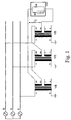
- fig. 1 shows a system of potential transformers connected to a protecting system
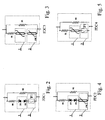
- fig. 2 the first variant of the protecting system embodiment FDC1, fig. 3 - the second variant of the protecting system embodiment FDC2, fig. 4 - the third variant of the protecting system embodiment FDC3, and fig. 5 - the fourth variant of the protecting system embodiment FDC4.
- auxiliary windings of three single-phase potential transformers VT1 , VT2 , VT3 are connected with one another to form an open delta arrangement.
- Primary windings A-N are directly connected with a three-phase network RST and earth.
- the terminals of the secondary windings a-n of the individual transformers are the working outputs of these transformers.
- the terminals of the auxiliary secondary windings da and dn of the transformers are connected with one another in such way that the terminal da of the auxiliary secondary winding of the transformer VT1 is connected with the input of the protection system FDC , whose output is connected with the terminal dn of the auxiliary secondary winding of the third transformer VT3, and whose terminal da is connected with the terminal dn of the auxiliary secondary winding of the second transformer VT2.
- the terminal da of the second transformer VT2 is connected with the terminal dn of the first transformer VT1 .
- the terminal da of the first transformer VT1 and the terminal dn of the third transformer VT3 voltage U 0 appears, which is applied to the terminals of the protection system FDC.
- the protecting system FDC comprises branches interconnected in parallel, and in the first FDC1 variant of the system embodiment, one branch contains: an attenuating resistor R1 , two Zener diodes D1 , D2 push-pull connected with one another and a bimetallic circuit breaker TF1 , interconnected in series. Two push-pull connected Zener diodes can be substituted with one bi-directional Zener diode, which is not shown in the drawing.
- the other branch of the system contains a resistor R2.
- one branch contains: resistor R1 , two Zener diodes D1,D2 push-pull connected with one another and a PTC resistor, interconnected in series.
- the two push-pull connected Zener diodes can be substituted with one bi-directional Zener diode, which is not shown in the drawing.
- the other branch of the system contains a resistor R2.
- one branch contains: a resistor R1 , a varistor and a PTC resistor, interconnected in series.
- the other branch of the system contains a resistor R2.
- one branch contains: resistor R1 , a varistor and a bimetallic circuit breaker TF1 , interconnected in series.
- the other branch of the system contains a resistor R2.
- the resistor R2 has a value considerably larger than the resistance from the resistor R1 .
- voltage U 0 has a non-zero value, but less than the value of the threshold voltage of the element with a threshold voltage and current characteristic.
Abstract
Description
- The subject of the invention is a protection system for medium-voltage potential transformers, finding application in the attenuation of ferroresonant states occurring in at least one of three potential transformers in a three-phase medium-voltage network.
- For the attenuation of ferroresonant states in electrical equipment, and especially in potential transformers, a protecting resistor of a resistance of several dozen ohms is typically used. Such a resistor is connected to three auxiliary secondary windings of three single-phase transformers forming an open delta system. Though this solution employs a simple design, it has significant disadvantages. In case of sustained unbalance in the supply network, the small resistance value of the protecting resistor, which is required for the effectiveness of ferroresonant oscillation attenuation, brings about the danger of thermal damage to the transformer or the resistor itself. In practice, attenuating resistors of powers of several hundred watts and of large dimensions are used.
- The solution to the thermal problem related to the presence of the damping resistor in the case of significant network asymmetry resulting form a prolonged earthfault was presented in DE 1265836, describing a circuit for damping ferroresonant oscillations, in which the damping resistor is connected to the open-delta arranged auxiliary windings of the three single-phase voltage transformers by means of working contacts of a relay or relays, which are connected to the secondary windings of the voltage transformers. The disadvantage of such a solution is that it requires additional wiring between the coils of the relays and the secondary windings of the voltage transformers. Another disadvantage of this solution is that in the case of a small network asymmetry resulting from e.g. unbalanced load, the zero-sequence voltage will result in current flow through the resistor, as it may be disconnected only in the case of an earth-fault condition. This may result in unnecessary heating of the resistor as well as in loading of the voltage transformers during normal service conditions, as the circuit described does not contain a temperature-sensitive element. The problem how to avoid the presence of the damping load during the normal service condition was presented in GB 1150865, describing a controlled anti-ferroresonance circuit for a single-phase capacitive voltage transformer, including a damping burden, a gate-controlled a.c. semiconductor switch arranged to connect the damping burden to the intermediate voltage transformer when the switch is conductive, and triggering means for rendering the switch conductive throughout occurrence of unwanted oscillations. The disadvantage of the solution is that it requires means for detecting the unwanted oscillations in order to provide the triggering signal making the semi-conducting switch conductive for a pre-defined time necessary to damp the unwanted oscillations.
- PTC resistors, bimetallic circuit breakers or thermal fuses are commonly used to protect electrical equipment against thermal damage caused, for example, by voltage overload.
- For example, a module protecting a telecommunication system, which consists of a PTC thermistor connected in series into the subscriber's line winding and a thyristor diode which is connected in parallel between the subscriber's line winding and ground is known from a German patent application No. 3621200. If undesired voltage appears in the subscriber's line, then current flowing through the thyristor diode heats it up and consequently the thermistor is heated up as well, because the diode is thermally connected with the PTC thermistor. As a result, the thermistor resistance increases and the voltage overload is reduced.
- The essence of the medium-voltage potential transformers protection system comprising an attenuating resistor connected into the open delta system of three auxiliary secondary windings of three single-phase transformers, which is deactivated by a switching device is that the switching device has a form of a thermal fuse, which is connected in series between the output of the auxiliary secondary winding of one of the single-phase transformers and the attenuating resistor by means of an element with a threshold voltage and current characteristic.
- Preferably the thermal fuse has the form of a bimetallic circuit breaker, and the element with threshold voltage and current characteristic has the form of two Zener diodes push-pull connected with one another.
- As an alternative, the thermal fuse has the form of a PTC resistor, and the element with the threshold characteristic has the form of two Zener diodes push-pull connected with one another.
- Preferably the thermal fuse is a PTC resistor, and the element with the threshold characteristic is a varistor.
- As an alternative, the thermal fuse is a bimetallic circuit breaker, and the element with the threshold voltage and current characteristic is a varistor.
- The advantage of the inventive system is that it assures the attenuation of ferroresonant oscillations while being insensitive to small values of zero-sequence voltage, which occur in case of small unbalance in a three-phase network. In case of sustained zero-sequence voltage, for instance one generated as a result of an earth fault of one of the phases, the use of a thermal fuse provides additional protection of the transformers and of the elements of the protection system that protects the transformers against damage. The use of the thermal protection allows to decrease the thermal power of the attenuating resistor compared to earlier solutions. That is why the inventive system is efficient and its dimensions are small compared to existing protecting devices.
- The subject of the invention is presented in an embodiment in the drawing, where fig. 1 shows a system of potential transformers connected to a protecting system, fig. 2 - the first variant of the protecting system embodiment FDC1, fig. 3 - the second variant of the protecting system embodiment FDC2, fig. 4 - the third variant of the protecting system embodiment FDC3, and fig. 5 - the fourth variant of the protecting system embodiment FDC4.
- The auxiliary windings of three single-phase potential transformers VT1, VT2, VT3 are connected with one another to form an open delta arrangement. Primary windings A-N are directly connected with a three-phase network RST and earth. The terminals of the secondary windings a-n of the individual transformers are the working outputs of these transformers. The terminals of the auxiliary secondary windings da and dn of the transformers are connected with one another in such way that the terminal da of the auxiliary secondary winding of the transformer VT1 is connected with the input of the protection system FDC, whose output is connected with the terminal dn of the auxiliary secondary winding of the third transformer VT3, and whose terminal da is connected with the terminal dn of the auxiliary secondary winding of the second transformer VT2. Next, the terminal da of the second transformer VT2 is connected with the terminal dn of the first transformer VT1. During the device operation, between the terminal da of the first transformer VT1 and the terminal dn of the third transformer VT3 voltage U 0 appears, which is applied to the terminals of the protection system FDC.
- The protecting system FDC comprises branches interconnected in parallel, and in the first FDC1 variant of the system embodiment, one branch contains: an attenuating resistor R1, two Zener diodes D1, D2 push-pull connected with one another and a bimetallic circuit breaker TF1, interconnected in series. Two push-pull connected Zener diodes can be substituted with one bi-directional Zener diode, which is not shown in the drawing. The other branch of the system contains a resistor R2.
- In the second FDC2 variant of the system embodiment, one branch contains: resistor R1, two Zener diodes D1,D2 push-pull connected with one another and a PTC resistor, interconnected in series. The two push-pull connected Zener diodes can be substituted with one bi-directional Zener diode, which is not shown in the drawing. The other branch of the system contains a resistor R2.
- In the third FDC3 variant of the system embodiment, one branch contains: a resistor R1, a varistor and a PTC resistor, interconnected in series. The other branch of the system contains a resistor R2.
- In the fourth FDC4 variant of the system embodiment, one branch contains: resistor R1, a varistor and a bimetallic circuit breaker TF1, interconnected in series. The other branch of the system contains a resistor R2.
- In all variants of the invention embodiment the resistor R2 has a value considerably larger than the resistance from the resistor R1.
- The operation of the inventive system is as follows:
- In case of full balance in a three-phase network, the zero-sequence voltage U 0 has a value = 0 and no current flows through the protection system FDC.
In case of insignificant unbalance in the three-phase network, voltage U 0 has a non-zero value, but less than the value of the threshold voltage of the element with a threshold voltage and current characteristic. In such case, current of a value of U 0 /R2 flows through the protection system FDC. Since the resistance of the resistor R2 has a large value (R2>>R1), current flowing through the protection system FDC has a small value. Therefore, also the thermal power emitted in the protection system FDC is in such case insignificant. For example: if R2 has a value of 200 Ohm, then if the value U 0 =10V, the thermal power emitted in the system FDC has a value of 0.5W. - In the event that a ferroresonant state occurs in the three-phase network, voltage U 0 has a value exceeding the threshold value of the element with threshold voltage and current characteristic. In that case, current flows through the resistor R1. Due to a small value of the resistor R1 a very rapid attenuation of ferroresonant oscillations occurs. Since the branch with the resistor R1 works for a short time, thermal energy emitted in this branch has an insignificant value. Therefore neither the branch elements overheat nor the thermal fuse is actuated.
- In the event that a considerable sustained unbalance in a three-phase network occurs, which may be caused, for instance, by an earth fault of one of the phase conductors, voltage U 0 has also a value bigger than the threshold voltage of the element with threshold voltage and current characteristic. Therefore a current of high intensity flows through the branch with the resistor R1. However, since such condition does not require the action of the attenuating resistor, the thermal fuse in the form of a bimetallic fuse or a PTC resistor causes a large increase in the resultant resistance of the branch that contains the resistor R1, or its complete disconnection. Then no current flows through this branch, or low-intensity current flows through it. When the cause of the unbalance disappears and the thermal fuse cools down, the system will reset.
Claims (5)
- A protecting system for medium-voltage potential transformers , comprising an attenuating resistor (R1) connected into the open delta system of three auxiliary secondary windings of three single-phase transformers (VT1, VT2, VT3), which is deactivated by a switching device characterized in that the switching device has a form of a thermal fuse (2) which is connected in series between the output of the auxiliary secondary winding of one of the single-phase transformers (VT1, VT2, VT3) and the attenuating resistor (R1) by means of an element with a threshold voltage and current characteristic (1).
- A system according to claim 1, characterised in that the thermal fuse (2) has the form of a bimetallic circuit breaker (TF1), and the element with a threshold voltage and current characteristic has the form of two Zener diodes (D1, D2), push-pull connected with one another.
- A system according to claim 1, characterised in that the thermal fuse (2) has the form of a PTC resistor, and the element with a threshold voltage and current characteristic has the form of two Zener diodes push-pull connected with one another.
- A system according to claim 1, characterised in that the thermal fuse (2) is a PTC resistor, and the element with a threshold voltage and current characteristic is a varistor.
- A system according to claim 1, characterised in that the thermal fuse (2) is a bimetallic circuit breaker (TF1), and the element with a threshold voltage and current characteristic is a varistor.
Applications Claiming Priority (2)
| Application Number | Priority Date | Filing Date | Title |
|---|---|---|---|
| PL361320A PL203206B1 (en) | 2003-07-17 | 2003-07-17 | Protection system for the medium tension voltage transformers |
| PCT/PL2004/000053 WO2005008859A1 (en) | 2003-07-17 | 2004-07-08 | A protection system for medium-voltage potential transformers |
Publications (2)
| Publication Number | Publication Date |
|---|---|
| EP1647079A1 EP1647079A1 (en) | 2006-04-19 |
| EP1647079B1 true EP1647079B1 (en) | 2006-12-06 |
Family
ID=34075206
Family Applications (1)
| Application Number | Title | Priority Date | Filing Date |
|---|---|---|---|
| EP04748877A Not-in-force EP1647079B1 (en) | 2003-07-17 | 2004-07-08 | Protection system for medium-voltage potential transformers |
Country Status (10)
| Country | Link |
|---|---|
| US (1) | US7558032B2 (en) |
| EP (1) | EP1647079B1 (en) |
| CN (1) | CN100533906C (en) |
| AT (1) | ATE347745T1 (en) |
| DE (1) | DE602004003586T2 (en) |
| ES (1) | ES2279406T3 (en) |
| PL (1) | PL203206B1 (en) |
| RU (1) | RU2332768C2 (en) |
| UA (1) | UA85683C2 (en) |
| WO (1) | WO2005008859A1 (en) |
Cited By (1)
| Publication number | Priority date | Publication date | Assignee | Title |
|---|---|---|---|---|
| EP2293401A1 (en) * | 2009-09-07 | 2011-03-09 | ABB Research Ltd. | Protective system for voltage transformers |
Families Citing this family (12)
| Publication number | Priority date | Publication date | Assignee | Title |
|---|---|---|---|---|
| EP1727257A1 (en) * | 2005-05-25 | 2006-11-29 | ABB Sp.zo.o. | A protection circuit for potential transformers |
| CN100373728C (en) * | 2005-11-21 | 2008-03-05 | 华北电力大学(北京) | Controllable damp device of ferromagnetic resonance for electromagnetic voltage transformer for distribution network |
| US20100090789A1 (en) * | 2008-10-14 | 2010-04-15 | Middle Atlantic Products, Inc. | Method, system and transformer for mitigating harmonics |
| CN103606904A (en) * | 2013-11-26 | 2014-02-26 | 国家电网公司 | Device and method for restraining ferromagnetic resonance of extra-high voltage non-load busbar |
| SG10201802590PA (en) | 2014-06-11 | 2018-05-30 | Asator Global Tech Llc | Surge suppression system for medium and high voltage |
| RU2633958C2 (en) * | 2016-12-19 | 2017-10-20 | Ариф Гасан оглы Аслан-заде | Device for interphase current distribution (versions) |
| GB2568963B (en) * | 2017-12-04 | 2022-06-22 | Eaton Intelligent Power Ltd | Voltage transformer |
| EP3499670A1 (en) * | 2017-12-18 | 2019-06-19 | ABB Schweiz AG | Crowbar overvoltage protection with current limiting function |
| WO2019131719A1 (en) | 2017-12-27 | 2019-07-04 | 神戸天然物化学株式会社 | Production of highly fat-soluble phosphoramidite |
| CN110445109B (en) * | 2018-05-04 | 2022-03-29 | 南京南瑞继保电气有限公司 | Method and device for rapidly eliminating ferromagnetic resonance of voltage transformer |
| CN110768222B (en) * | 2019-10-24 | 2022-07-08 | 深圳供电局有限公司 | Voltage transformer resonance elimination device and protection equipment |
| EP4208885A1 (en) * | 2020-11-09 | 2023-07-12 | RIPD IP Development Ltd | Surge protective device including bimetallic fuse element |
Family Cites Families (14)
| Publication number | Priority date | Publication date | Assignee | Title |
|---|---|---|---|---|
| DE1265836B (en) * | 1965-04-20 | 1968-04-11 | Siemens Ag | Circuit arrangement for damping breakdown vibrations |
| US3401272A (en) * | 1965-08-30 | 1968-09-10 | Westinghouse Electric Corp | Ferroresonant transient suppression system |
| US3467903A (en) * | 1966-10-14 | 1969-09-16 | Franklin Electric Co Inc | Motor with thermal cutout |
| ES350010A1 (en) * | 1967-02-06 | 1970-04-16 | Micafil Ag | Improvements relating to Capacitive Voltage Transformers |
| US3569673A (en) * | 1969-03-03 | 1971-03-09 | Texas Instruments Inc | Temperature control and indicating system |
| CH604349A5 (en) * | 1977-01-19 | 1978-09-15 | Micafil Ag | |
| DE2824233A1 (en) * | 1978-06-02 | 1979-12-06 | Ritz Messwandler Kg | Electric power substation relaxation oscillation damping appts. - uses ballast resistor and associated heat accumulator plate arranged in housing with excess temp. protection circuit |
| US4358813A (en) * | 1980-11-20 | 1982-11-09 | Matsushita Electric Industrial Co., Ltd. | Ignition apparatus for a burner |
| US4466039A (en) * | 1982-07-29 | 1984-08-14 | Mcgraw-Edison Company | Open circuit current transformer protection circuit |
| WO1993013429A1 (en) * | 1985-08-07 | 1993-07-08 | Toshisada Fujiki | Voltage detector |
| DE8700256U1 (en) * | 1987-01-07 | 1988-05-05 | Robert Bosch Gmbh, 7000 Stuttgart, De | |
| JPH0816470A (en) * | 1994-07-04 | 1996-01-19 | Hitachi Ltd | Parallel computer |
| DE19728763B4 (en) * | 1997-07-07 | 2007-10-31 | Reitter & Schefenacker Gmbh & Co. Kg | Circuit device for protecting current-driven light sources, in particular LEDs, for signaling or lighting purposes |
| DE19923360B4 (en) * | 1999-05-21 | 2010-01-07 | Werner Turck Gmbh & Co. Kg | Voltage transformer with a potential separation protection |
-
2003
- 2003-07-17 PL PL361320A patent/PL203206B1/en unknown
-
2004
- 2004-07-08 RU RU2006104850/09A patent/RU2332768C2/en not_active IP Right Cessation
- 2004-07-08 ES ES04748877T patent/ES2279406T3/en active Active
- 2004-07-08 AT AT04748877T patent/ATE347745T1/en not_active IP Right Cessation
- 2004-07-08 EP EP04748877A patent/EP1647079B1/en not_active Not-in-force
- 2004-07-08 US US10/564,574 patent/US7558032B2/en not_active Expired - Fee Related
- 2004-07-08 DE DE602004003586T patent/DE602004003586T2/en active Active
- 2004-07-08 WO PCT/PL2004/000053 patent/WO2005008859A1/en active IP Right Grant
- 2004-07-08 CN CNB2004800202830A patent/CN100533906C/en not_active Expired - Fee Related
- 2004-08-07 UA UAA200601525A patent/UA85683C2/en unknown
Cited By (2)
| Publication number | Priority date | Publication date | Assignee | Title |
|---|---|---|---|---|
| EP2293401A1 (en) * | 2009-09-07 | 2011-03-09 | ABB Research Ltd. | Protective system for voltage transformers |
| EP2293402A1 (en) * | 2009-09-07 | 2011-03-09 | ABB Research Ltd. | Protective system for voltage transformers |
Also Published As
| Publication number | Publication date |
|---|---|
| DE602004003586D1 (en) | 2007-01-18 |
| RU2006104850A (en) | 2006-06-27 |
| UA85683C2 (en) | 2009-02-25 |
| CN1823460A (en) | 2006-08-23 |
| EP1647079A1 (en) | 2006-04-19 |
| ATE347745T1 (en) | 2006-12-15 |
| ES2279406T3 (en) | 2007-08-16 |
| WO2005008859A1 (en) | 2005-01-27 |
| US20070103823A1 (en) | 2007-05-10 |
| RU2332768C2 (en) | 2008-08-27 |
| CN100533906C (en) | 2009-08-26 |
| PL361320A1 (en) | 2005-01-24 |
| DE602004003586T2 (en) | 2007-09-27 |
| US7558032B2 (en) | 2009-07-07 |
| PL203206B1 (en) | 2009-09-30 |
Similar Documents
| Publication | Publication Date | Title |
|---|---|---|
| JP4109310B2 (en) | Overcurrent protection system and electric circuit provided with the same | |
| EP1727257A1 (en) | A protection circuit for potential transformers | |
| EP1647079B1 (en) | Protection system for medium-voltage potential transformers | |
| US4459632A (en) | Voltage-limiting circuit | |
| SK18498A3 (en) | Disconnector for surge arrester | |
| JP5165797B2 (en) | Overload prevention of voltage drop device | |
| JP7264920B2 (en) | Multistage protection device for overcurrent and overvoltage protected transfer of electrical energy | |
| JP7110404B2 (en) | Multistage protective device for overcurrent and overvoltage protected transmission of electrical energy | |
| WO2011070235A1 (en) | Electronic protection circuit and protection device | |
| RU2619777C2 (en) | Device for protection of electrical consumers from overvoltage in single-phase ac networks | |
| US6992874B2 (en) | Dual stage current limiting surge protector system | |
| EP1220410A2 (en) | An overvoltage protection accessory device for a residual current circuit breaker | |
| CN210142902U (en) | Current limiting circuit | |
| KR100756750B1 (en) | Motor protector apparatus having current-limit property | |
| JP2005285717A (en) | Circuit protection device | |
| WO2000031851A1 (en) | Current limiting device | |
| KR970001861Y1 (en) | Load protection device | |
| KR100990606B1 (en) | Electric Cooker | |
| Strobel | Equipment and Apparatus Circuit Protection | |
| JPH0118651B2 (en) |
Legal Events
| Date | Code | Title | Description |
|---|---|---|---|
| PUAI | Public reference made under article 153(3) epc to a published international application that has entered the european phase |
Free format text: ORIGINAL CODE: 0009012 |
|
| 17P | Request for examination filed |
Effective date: 20060110 |
|
| AK | Designated contracting states |
Kind code of ref document: A1 Designated state(s): AT BE BG CH CY CZ DE DK EE ES FI FR GB GR HU IE IT LI LU MC NL PL PT RO SE SI SK TR |
|
| GRAP | Despatch of communication of intention to grant a patent |
Free format text: ORIGINAL CODE: EPIDOSNIGR1 |
|
| RTI1 | Title (correction) |
Free format text: PROTECTION SYSTEM FOR MEDIUM-VOLTAGE POTENTIAL TRANSFORMERS |
|
| DAX | Request for extension of the european patent (deleted) | ||
| GRAS | Grant fee paid |
Free format text: ORIGINAL CODE: EPIDOSNIGR3 |
|
| GRAA | (expected) grant |
Free format text: ORIGINAL CODE: 0009210 |
|
| AK | Designated contracting states |
Kind code of ref document: B1 Designated state(s): AT BE BG CH CY CZ DE DK EE ES FI FR GB GR HU IE IT LI LU MC NL PL PT RO SE SI SK TR |
|
| PG25 | Lapsed in a contracting state [announced via postgrant information from national office to epo] |
Ref country code: SI Free format text: LAPSE BECAUSE OF FAILURE TO SUBMIT A TRANSLATION OF THE DESCRIPTION OR TO PAY THE FEE WITHIN THE PRESCRIBED TIME-LIMIT Effective date: 20061206 Ref country code: SK Free format text: LAPSE BECAUSE OF FAILURE TO SUBMIT A TRANSLATION OF THE DESCRIPTION OR TO PAY THE FEE WITHIN THE PRESCRIBED TIME-LIMIT Effective date: 20061206 Ref country code: DK Free format text: LAPSE BECAUSE OF FAILURE TO SUBMIT A TRANSLATION OF THE DESCRIPTION OR TO PAY THE FEE WITHIN THE PRESCRIBED TIME-LIMIT Effective date: 20061206 Ref country code: BE Free format text: LAPSE BECAUSE OF FAILURE TO SUBMIT A TRANSLATION OF THE DESCRIPTION OR TO PAY THE FEE WITHIN THE PRESCRIBED TIME-LIMIT Effective date: 20061206 Ref country code: FI Free format text: LAPSE BECAUSE OF FAILURE TO SUBMIT A TRANSLATION OF THE DESCRIPTION OR TO PAY THE FEE WITHIN THE PRESCRIBED TIME-LIMIT Effective date: 20061206 Ref country code: CH Free format text: LAPSE BECAUSE OF FAILURE TO SUBMIT A TRANSLATION OF THE DESCRIPTION OR TO PAY THE FEE WITHIN THE PRESCRIBED TIME-LIMIT Effective date: 20061206 Ref country code: AT Free format text: LAPSE BECAUSE OF FAILURE TO SUBMIT A TRANSLATION OF THE DESCRIPTION OR TO PAY THE FEE WITHIN THE PRESCRIBED TIME-LIMIT Effective date: 20061206 Ref country code: NL Free format text: LAPSE BECAUSE OF FAILURE TO SUBMIT A TRANSLATION OF THE DESCRIPTION OR TO PAY THE FEE WITHIN THE PRESCRIBED TIME-LIMIT Effective date: 20061206 Ref country code: RO Free format text: LAPSE BECAUSE OF FAILURE TO SUBMIT A TRANSLATION OF THE DESCRIPTION OR TO PAY THE FEE WITHIN THE PRESCRIBED TIME-LIMIT Effective date: 20061206 Ref country code: PL Free format text: LAPSE BECAUSE OF FAILURE TO SUBMIT A TRANSLATION OF THE DESCRIPTION OR TO PAY THE FEE WITHIN THE PRESCRIBED TIME-LIMIT Effective date: 20061206 Ref country code: LI Free format text: LAPSE BECAUSE OF FAILURE TO SUBMIT A TRANSLATION OF THE DESCRIPTION OR TO PAY THE FEE WITHIN THE PRESCRIBED TIME-LIMIT Effective date: 20061206 |
|
| REG | Reference to a national code |
Ref country code: GB Ref legal event code: FG4D |
|
| RAP2 | Party data changed (patent owner data changed or rights of a patent transferred) |
Owner name: ABB RESEARCH LTD. |
|
| REG | Reference to a national code |
Ref country code: CH Ref legal event code: EP |
|
| REG | Reference to a national code |
Ref country code: IE Ref legal event code: FG4D |
|
| REF | Corresponds to: |
Ref document number: 602004003586 Country of ref document: DE Date of ref document: 20070118 Kind code of ref document: P |
|
| NLT2 | Nl: modifications (of names), taken from the european patent patent bulletin |
Owner name: ABB RESEARCH LTD. Effective date: 20061227 |
|
| PG25 | Lapsed in a contracting state [announced via postgrant information from national office to epo] |
Ref country code: BG Free format text: LAPSE BECAUSE OF FAILURE TO SUBMIT A TRANSLATION OF THE DESCRIPTION OR TO PAY THE FEE WITHIN THE PRESCRIBED TIME-LIMIT Effective date: 20070306 Ref country code: SE Free format text: LAPSE BECAUSE OF FAILURE TO SUBMIT A TRANSLATION OF THE DESCRIPTION OR TO PAY THE FEE WITHIN THE PRESCRIBED TIME-LIMIT Effective date: 20070306 |
|
| PG25 | Lapsed in a contracting state [announced via postgrant information from national office to epo] |
Ref country code: PT Free format text: LAPSE BECAUSE OF FAILURE TO SUBMIT A TRANSLATION OF THE DESCRIPTION OR TO PAY THE FEE WITHIN THE PRESCRIBED TIME-LIMIT Effective date: 20070507 |
|
| NLV1 | Nl: lapsed or annulled due to failure to fulfill the requirements of art. 29p and 29m of the patents act | ||
| REG | Reference to a national code |
Ref country code: CH Ref legal event code: PL |
|
| ET | Fr: translation filed | ||
| REG | Reference to a national code |
Ref country code: ES Ref legal event code: FG2A Ref document number: 2279406 Country of ref document: ES Kind code of ref document: T3 |
|
| PLBE | No opposition filed within time limit |
Free format text: ORIGINAL CODE: 0009261 |
|
| STAA | Information on the status of an ep patent application or granted ep patent |
Free format text: STATUS: NO OPPOSITION FILED WITHIN TIME LIMIT |
|
| 26N | No opposition filed |
Effective date: 20070907 |
|
| PG25 | Lapsed in a contracting state [announced via postgrant information from national office to epo] |
Ref country code: GR Free format text: LAPSE BECAUSE OF FAILURE TO SUBMIT A TRANSLATION OF THE DESCRIPTION OR TO PAY THE FEE WITHIN THE PRESCRIBED TIME-LIMIT Effective date: 20070307 Ref country code: MC Free format text: LAPSE BECAUSE OF NON-PAYMENT OF DUE FEES Effective date: 20070731 |
|
| PG25 | Lapsed in a contracting state [announced via postgrant information from national office to epo] |
Ref country code: IE Free format text: LAPSE BECAUSE OF NON-PAYMENT OF DUE FEES Effective date: 20070709 |
|
| PG25 | Lapsed in a contracting state [announced via postgrant information from national office to epo] |
Ref country code: EE Free format text: LAPSE BECAUSE OF FAILURE TO SUBMIT A TRANSLATION OF THE DESCRIPTION OR TO PAY THE FEE WITHIN THE PRESCRIBED TIME-LIMIT Effective date: 20061206 |
|
| PG25 | Lapsed in a contracting state [announced via postgrant information from national office to epo] |
Ref country code: CY Free format text: LAPSE BECAUSE OF FAILURE TO SUBMIT A TRANSLATION OF THE DESCRIPTION OR TO PAY THE FEE WITHIN THE PRESCRIBED TIME-LIMIT Effective date: 20061206 Ref country code: LU Free format text: LAPSE BECAUSE OF NON-PAYMENT OF DUE FEES Effective date: 20070708 |
|
| PG25 | Lapsed in a contracting state [announced via postgrant information from national office to epo] |
Ref country code: HU Free format text: LAPSE BECAUSE OF FAILURE TO SUBMIT A TRANSLATION OF THE DESCRIPTION OR TO PAY THE FEE WITHIN THE PRESCRIBED TIME-LIMIT Effective date: 20070607 |
|
| REG | Reference to a national code |
Ref country code: FR Ref legal event code: PLFP Year of fee payment: 12 |
|
| REG | Reference to a national code |
Ref country code: FR Ref legal event code: PLFP Year of fee payment: 13 |
|
| REG | Reference to a national code |
Ref country code: FR Ref legal event code: PLFP Year of fee payment: 14 |
|
| PGFP | Annual fee paid to national office [announced via postgrant information from national office to epo] |
Ref country code: TR Payment date: 20150708 Year of fee payment: 12 |
|
| REG | Reference to a national code |
Ref country code: FR Ref legal event code: PLFP Year of fee payment: 15 |
|
| PGFP | Annual fee paid to national office [announced via postgrant information from national office to epo] |
Ref country code: DE Payment date: 20180723 Year of fee payment: 15 Ref country code: IT Payment date: 20180724 Year of fee payment: 15 Ref country code: ES Payment date: 20180829 Year of fee payment: 15 Ref country code: FR Payment date: 20180725 Year of fee payment: 15 |
|
| PGFP | Annual fee paid to national office [announced via postgrant information from national office to epo] |
Ref country code: BE Payment date: 20180914 Year of fee payment: 7 |
|
| PGFP | Annual fee paid to national office [announced via postgrant information from national office to epo] |
Ref country code: CZ Payment date: 20190702 Year of fee payment: 16 |
|
| REG | Reference to a national code |
Ref country code: DE Ref legal event code: R119 Ref document number: 602004003586 Country of ref document: DE |
|
| REG | Reference to a national code |
Ref country code: GB Ref legal event code: 732E Free format text: REGISTERED BETWEEN 20200206 AND 20200212 |
|
| GBPC | Gb: european patent ceased through non-payment of renewal fee |
Effective date: 20190708 |
|
| PG25 | Lapsed in a contracting state [announced via postgrant information from national office to epo] |
Ref country code: DE Free format text: LAPSE BECAUSE OF NON-PAYMENT OF DUE FEES Effective date: 20200201 Ref country code: GB Free format text: LAPSE BECAUSE OF NON-PAYMENT OF DUE FEES Effective date: 20190708 |
|
| PG25 | Lapsed in a contracting state [announced via postgrant information from national office to epo] |
Ref country code: FR Free format text: LAPSE BECAUSE OF NON-PAYMENT OF DUE FEES Effective date: 20190731 |
|
| PG25 | Lapsed in a contracting state [announced via postgrant information from national office to epo] |
Ref country code: IT Free format text: LAPSE BECAUSE OF NON-PAYMENT OF DUE FEES Effective date: 20190708 |
|
| REG | Reference to a national code |
Ref country code: ES Ref legal event code: FD2A Effective date: 20201126 |
|
| PG25 | Lapsed in a contracting state [announced via postgrant information from national office to epo] |
Ref country code: CZ Free format text: LAPSE BECAUSE OF NON-PAYMENT OF DUE FEES Effective date: 20200708 Ref country code: ES Free format text: LAPSE BECAUSE OF NON-PAYMENT OF DUE FEES Effective date: 20190709 |
|
| PG25 | Lapsed in a contracting state [announced via postgrant information from national office to epo] |
Ref country code: TR Free format text: LAPSE BECAUSE OF NON-PAYMENT OF DUE FEES Effective date: 20160708 |