EP1646822B1 - Gelenkkettenvorrichtung - Google Patents
Gelenkkettenvorrichtung Download PDFInfo
- Publication number
- EP1646822B1 EP1646822B1 EP04741298A EP04741298A EP1646822B1 EP 1646822 B1 EP1646822 B1 EP 1646822B1 EP 04741298 A EP04741298 A EP 04741298A EP 04741298 A EP04741298 A EP 04741298A EP 1646822 B1 EP1646822 B1 EP 1646822B1
- Authority
- EP
- European Patent Office
- Prior art keywords
- shape memory
- wire
- link
- tensioning
- link chain
- Prior art date
- Legal status (The legal status is an assumption and is not a legal conclusion. Google has not performed a legal analysis and makes no representation as to the accuracy of the status listed.)
- Expired - Lifetime
Links
Images


Classifications
-
- F—MECHANICAL ENGINEERING; LIGHTING; HEATING; WEAPONS; BLASTING
- F16—ENGINEERING ELEMENTS AND UNITS; GENERAL MEASURES FOR PRODUCING AND MAINTAINING EFFECTIVE FUNCTIONING OF MACHINES OR INSTALLATIONS; THERMAL INSULATION IN GENERAL
- F16M—FRAMES, CASINGS OR BEDS OF ENGINES, MACHINES OR APPARATUS, NOT SPECIFIC TO ENGINES, MACHINES OR APPARATUS PROVIDED FOR ELSEWHERE; STANDS; SUPPORTS
- F16M11/00—Stands or trestles as supports for apparatus or articles placed thereon ; Stands for scientific apparatus such as gravitational force meters
- F16M11/20—Undercarriages with or without wheels
- F16M11/24—Undercarriages with or without wheels changeable in height or length of legs, also for transport only, e.g. by means of tubes screwed into each other
- F16M11/40—Undercarriages with or without wheels changeable in height or length of legs, also for transport only, e.g. by means of tubes screwed into each other by means of coilable or bendable legs or spiral shaped legs
-
- A—HUMAN NECESSITIES
- A61—MEDICAL OR VETERINARY SCIENCE; HYGIENE
- A61B—DIAGNOSIS; SURGERY; IDENTIFICATION
- A61B90/00—Instruments, implements or accessories specially adapted for surgery or diagnosis and not covered by any of the groups A61B1/00 - A61B50/00, e.g. for luxation treatment or for protecting wound edges
- A61B90/50—Supports for surgical instruments, e.g. articulated arms
-
- F—MECHANICAL ENGINEERING; LIGHTING; HEATING; WEAPONS; BLASTING
- F16—ENGINEERING ELEMENTS AND UNITS; GENERAL MEASURES FOR PRODUCING AND MAINTAINING EFFECTIVE FUNCTIONING OF MACHINES OR INSTALLATIONS; THERMAL INSULATION IN GENERAL
- F16M—FRAMES, CASINGS OR BEDS OF ENGINES, MACHINES OR APPARATUS, NOT SPECIFIC TO ENGINES, MACHINES OR APPARATUS PROVIDED FOR ELSEWHERE; STANDS; SUPPORTS
- F16M2200/00—Details of stands or supports
- F16M2200/02—Locking means
Definitions
- the present invention relates to a joint chain device which can be brought into a fixed state and in a flexible state.
- Generic Gelenkkettenvortechnischen find u.a. in holding systems for holding objects such as lamps, microphones, etc. application.
- medical retention systems for example, (neuro) surgical instruments are to be positioned in the region of an operative access via a universal clamp attached to the tip of the joint chain.
- the articulation chain must first be flexible until the doctor or a helper has brought the instrument in the desired position. Thereafter, the joint chain should be stiff so that the adjusted position is maintained during the surgical procedure.
- a major area of application of the described medical retention systems is in neurosurgery in cranial operations, ie operations in the cerebellum or cerebellum where parts of the cerebral lobes or the two cerebral or cerebellar hemispheres must be kept to one side or apart from one another To access the target region of the operation.
- cerebral spatulas which usually consist of metal and whose shape resembles the known wooden spatula, are attached to the universal clamp.
- a medical retention system with a joint chain is known, for example, under the name "DORO Reaktor System” from the company "pro medical instruments GmbH”.
- a tension wire which can be tensioned by means of a hand crank.
- the joint members of the joint chain are pressed against each other, so that the joint chain stiffened due to the friction between the joint members.
- the operation of the hand crank is carried out by the assistant of the surgeon. Due to the mechanical movement of the hand crank, it can cause shocks on the operating table and thus at the surgical site, the so-called operation site itself. Therefore, while operating the hand crank, the surgeon must secure the spatula with his working hand and constantly coordinate with his assistant. In addition to changing the position of the spatula so also reinforcing or loosening the tension of the joint chain interrupt the natural flow of the operation.
- the US 2002/058860 A1 describes a joint chain device in the form of a medical instrument holder, which is equipped with a number of joint members, a tensioning wire extending through the joint members and a tensioning device.
- the tensioning device is located at the proximal end of the tension wire and has on the tension wire attacking shape memory wires, which contract when current flows and thus act on the tension wire for tensioning the articulated chain.
- the DE 199 16 244 C1 describes a Bowden cable whose soul consists at least partially and preferably completely of a shape memory alloy.
- the shape memory alloy is used to better limit the tension that occurs when using the Bowden cable.
- the US 5,624,381 describes a medical instrument having articulated members and a tensioning cable extending through the articulating members. It is noted that the hinge members may also be made of a shape memory alloy.
- the object of the present invention is to provide an improved articulated chain device and an improved holding system, with which mechanical shocks during the manufacture or release of the voltage can be reduced.
- a joint chain device has a number of joint members, which form a joint chain, and a tensioning device, which comprises at least one tensioning cable extending through the joint members or at least one tensioning wire extending through the joint members.
- the link chain may be set in a fixed state by clamping the tension cable or wire in a fixed state in which adjacent link members are fixed substantially relative to each other, and by relaxing the tension cable or wire in a flexible state in which adjacent link members relative to each other, to be brought.
- substantially fixed to each other is to be understood here that the force that is necessary in the fixed state for moving the joint members, the force that is necessary in the flexible state, significantly exceeds.
- the joint chain device is designed such that the tensioning device comprises a shape memory element which is designed and arranged such that the fixed state can be brought about or canceled by changing the shape state of the shape memory element.
- the shape memory element here is an element made of a shape memory material, ie a material which, at a certain temperature, makes a transition from one molding state to another molding state which exceeds the usual temperature-induced expansion / contraction of the material.
- the tensioning cable extending through the joint members or the tensioning wire extending through the joint members is designed as a shape memory wire.
- the shape memory wire in this case forms the shape memory element of the clamping device.
- Shape memory wires change their length in response to a change in temperature.
- the shape memory wire can be brought to contract by electrical heating.
- the shortening of the wire leads to the fact that the joint members are fixed against each other. As the wire cools, it expands again, restoring the flexibility of the articulated chain.
- the shape memory wire itself may be part of a circuit for electrically heating the wire.
- a mechanical means for tensioning the wire, such as a crank, is not necessary in this embodiment.
- the shape memory element is made of a shape memory alloy with a two-way memory effect, referred to below as a two-way shape memory alloy.
- Two-way memory effect means that the shape memory alloy switches between two states of shape by heating and cooling so, for example, contracts when heated and expands again when cooled.
- the shape change in one direction for example, in an expanded state, must be brought about by an external force, while the return to the original shape, for example, a contracted state, by changing the temperature of the alloy is to bring about.
- a shape memory alloy that exhibits a one-way memory effect is hereinafter referred to as a disposable shape memory alloy.
- the two-way memory effect has the advantage that changing the shape of the shape memory element in both directions, and thus both the stiffening and the release of the joint members from each other, without mechanical aids to accomplish.
- a temperature change of the shape memory element can be brought about, to which it reacts with the change of its shape state.
- the change of the shape state of the shape memory element takes place smoothly and thus helps to avoid vibrations in the operating area.
- hinge members comprise metal, and in particular if they are made entirely of metal, it is possible to close the circuit for heating the shape memory wire with appropriate electrical insulation of the wire relative to the hinge members via the hinge members.
- the joint chain can also be designed so that each joint member has at least two through holes extending in its axial direction, for example. Through holes, and that the tensioning cable or the tensioning wire is guided at least from the proximal to the distal end of the articulated chain and back, so that the Circuit can also be closed without using the hinge members. This makes it possible to produce the joint members of an insulator material.
- the shape memory element for example, a nickel-titanium (Ni-Ti) alloy, a copper-aluminum-nickel (Cu-Al-Ni) alloy or a copper-zinc-aluminum (Cu-Zn-Al) - Alloy find use or any other shape memory alloy.
- the nickel-titanium alloy offers the possibility of a large travel, i. a great shape change, and a great force to realize when changing the shape.
- the nickel-titanium alloy has a high long-term stability.
- the shape memory element can also be made of or of another shape memory material. In question come in addition to alloys, for example, shape memory plastics.
- the articulated members can be made of plastic. Possibly. may be integrated into the plastic electrical conductors, which allow the manufacture of a tensioning cable or the tensioning wire and the hinge members comprehensive circuit.
- the hinge members may have a friction-enhancing surface structure on those surfaces which face adjacent hinge members.
- the friction-enhancing surface structure can be produced, for example, by coating or roughening the surface.
- An inventive holding system in particular for medical purposes, comprises a joint chain device according to the invention, a holding element which is designed to hold an object, in particular a medical instrument or tool, and a device for heating and / or cooling the shape memory element.
- the device for heating and / or cooling the shape memory element may in particular comprise an electric heater.
- FIG. 1 a surgical holding device with a joint chain device according to the invention shown.
- the holding device comprises a link chain 7, which is constructed from a number of joint members 10 and at one end, the so-called distal end or chain head, a universal clamp 9 as a holding element for holding a surgical instrument or tool, not shown in the figure, eg. a brain spatula, is arranged.
- a surgical instrument or tool not shown in the figure, eg. a brain spatula
- the articulated chain 7 is connected to a collar 6, which in turn is attached to a control unit 4.
- the control unit 4 is held by a fixing piece 5, with the aid of which the entire holding device can, for example, be attached to a holding frame or the like.
- the control unit 4 is powered by a power supply unit 1 with electricity. By means of a foot switch 2, the power can be switched on and off.
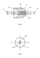
- a hinge member 10 of the link chain 7 is in the FIGS. 2 and 3 shown in detail.
- the hinge members 10 may be made of either metal or an electrical insulator, such as ceramic or plastic.
- Each hinge member 10 comprises a hemispherical recess 14 and a likewise hemispherical projection 13, which is arranged at the end facing away from the recess 14 of the hinge member 10.
- the dimensions of the recess 14 and the projection 13 are selected such that the projection 13 of a hinge member 10 can engage in the recess 14 of the adjacent hinge member 10.
- Each hinge member 10 is provided in the vicinity of its central axis A with two through holes 11a, 11b extending in the axial direction of the member 10, through which a shape memory wire 8 is guided freely from the proximal end of the articulated chain 7 to the distal end of the articulated chain 7 and back again. At the proximal end of the shape memory wire 8 is electrically connected to the control unit 4.
- the wire material used in the exemplary embodiment is a nickel-titanium alloy as a two-way shape memory alloy.
- other two-way shape memory alloys are also suitable for manufacturing of the shape memory wire 8.
- the properties of the nickel-titanium alloy used are chosen so that the shape memory wire 8 at a temperature of not more than about 50 ° C, in particular in the range of 40 ° C to 50 ° C and preferably in the lower half of this range, contracted and expanded at room temperature.
- the length of the shape memory wire 8 at room temperature is chosen such that the hinge members 10 are freely movable relative to each other.
- the shape memory wire 8 when the shape memory wire 8 is contracted, it presses the hemispherical projections 13 of the hinge members 10 into the hemispherical recess 14. Due to the friction generated by the pressure, the articulation chain 7 stiffens and holds the surgical instrument secured to its distal end in position which it has been brought before heating the shape memory wire 8.
- the surface of the recess 14 or that of the projection 13 may be provided with a friction-enhancing surface structure or coating. Of course, both surfaces may have a friction-enhancing structure or coating.
- the heating of the shape memory wire 8 takes place electrically and is controlled by the control unit 4. If the joint chain 7 is to stiffen, the doctor can turn on the supply of the control unit 4 with power via the foot switch 2, so that heating of the shape memory wire 8 takes place. If the articulated chain 7 is to be movable again, the doctor can interrupt the power supply of the control unit 4 by means of the foot switch 2 again.
- the control of the electric heating process is as follows: Once the power supply is activated, the shape memory wire 8 is supplied to a predetermined maximum power. The shape memory wire 8 is initially heated to more than about 40 ° C - 50 ° C, namely to about 60 ° C - 80 ° C and in particular to about 60 - 65 ° C. After the voltage is established in the shape memory wire 8, the control unit 4 moves the Power back to a value sufficient to hold the shape memory wire 8 to a value in the range of about 40 ° C to 50 ° C, in particular to a value in the lower half of this range.
- This possibility for returning or reducing the electrical power is based on a behavior of the shape memory wire 8 or the shape memory alloy, which is known as hysteresis and which, in simplified terms, means that in a certain temperature range T the length of the shape memory wire depends on it at a specific temperature, whether it has been heated or cooled to this temperature.
- the behavior is schematic in Fig. 4 shown.
- a temperature above the range T is used, which in the exemplary embodiment is approximately 60 ° C.-80 ° C.
- a lower temperature within the range T which in the exemplary embodiment is approximately 40 ° C.-50 ° C., is sufficient.
- the temperature In order to achieve expansion of the shape memory wire from the maximum contracted state, the temperature must be lowered to a temperature below the range T, in the exemplary embodiment, for example, to about 20 ° C.
- the adjusting ring 6 arranged at the proximal end of the articulated chain 7 serves to completely loosen the shape memory wire 8 when required.
- the complete loosening is important, for example, when the joint chain 7 is to be sterilized. The occurring during sterilization temperature of about 135 ° C would otherwise stress the shape memory wire 8, wherein the hinge members 10 could deform plastically due to the high temperature.
- the shape memory wire 8 with the adjusting ring 6 can be slightly biased again.
- the adjusting ring 6 also serves to readjust the shape memory wire 8. The readjustment may be useful in the course of time to compensate for signs of aging of the wire and / or the hinge members 10.
- the shape memory wire 8 is from the proximal end of the link chain 7 to the distal end of the link chain and led back. Alternatively, however, the shape memory wire 8 can also be guided only from the proximal to the distal end and fastened there. If the heating of the shape memory wire 8 is performed electrically, the current flowing through the shape memory wire 8 can then be returned via the hinge members 10, if they are made of metal or include metallic elements for conducting the current. Alternatively, the heating (possibly also the cooling) by means of a heating fluid (or cooling fluid), for example. Air, water or oil, take place.
- the hinge members can then be made entirely of an insulator material, for example ceramic or plastic.
- the shape memory alloy is selected such that the contraction of the shape memory wire at about 40 ° C to 50 ° C can be maintained, but this temperature is not necessarily predetermined, but only due to the application in the medical field. In the extra-medical field, shape memory alloys may well be used, in which the maintenance of the contraction of the shape memory wire requires significantly higher or lower temperatures. Possible transition temperatures from -120 ° C to + 120 ° C are dependent on the composition of the shape memory alloy.
- the shape of the hinge members represents only one possible suitable shape.
- the invention is not limited to the illustrated shape of the hinge members, but can be realized with articulated chains, the hinge members are shaped differently.
Landscapes
- Engineering & Computer Science (AREA)
- Health & Medical Sciences (AREA)
- Surgery (AREA)
- General Engineering & Computer Science (AREA)
- Life Sciences & Earth Sciences (AREA)
- Heart & Thoracic Surgery (AREA)
- General Health & Medical Sciences (AREA)
- Oral & Maxillofacial Surgery (AREA)
- Nuclear Medicine, Radiotherapy & Molecular Imaging (AREA)
- Biomedical Technology (AREA)
- Mechanical Engineering (AREA)
- Medical Informatics (AREA)
- Molecular Biology (AREA)
- Animal Behavior & Ethology (AREA)
- Pathology (AREA)
- Public Health (AREA)
- Veterinary Medicine (AREA)
- Surgical Instruments (AREA)
- Devices For Conveying Motion By Means Of Endless Flexible Members (AREA)
- Massaging Devices (AREA)
- Chain Conveyers (AREA)
- Transmission Devices (AREA)
- Hand Tools For Fitting Together And Separating, Or Other Hand Tools (AREA)
Description
- Die vorliegende Erfindung betrifft eine Gelenkkettenvorrichtung, die in einen fixierten Zustand und in einen flexiblen Zustand gebracht werden kann.
- Gattungsgemäße Gelenkkettenvorrichtungen finden u.a. in Haltesystemen zum Halten von Gegenständen wie Lampen, Mikrofonen, etc. Anwendung. In medizinischen Haltesystemen sollen bspw. über eine an der Spitze der Gelenkkette angebrachte Universalklammer (neuro-) chirurgische Instrumente im Bereich eines operativen Zugangs positioniert werden. Um ein genaues Positionieren zu ermöglichen, muss die Gelenkkette zunächst so lange flexibel sein, bis der Arzt oder eine Hilfsperson das Instrument in die gewünschte Position gebracht hat. Anschließend soll die Gelenkkette steif sein, damit die eingestellte Position während des operativen Eingriffs beibehalten wird.
- Ein Haupteinsatzbereich der beschriebenen medizinischen Haltesysteme liegt in der Neurochirurgie bei kranialen Operationen, d.h. bei Operationen im Bereich des Groß- oder des Kleinhirns, bei denen Teile der Hirnlappen bzw. die beiden Großhirn- oder Kleinhirnhemisphären zur Seite oder auseinander gehalten werden müssen, um die anatomische Zielregion der Operation zugänglich zu machen. An der Universalklammer werden zu diesem Zweck spezielle flache sog. Hirnspatel, die meist aus Metall bestehen und die in ihrer Form dem bekannten Mundspatel aus Holz ähneln, befestigt.
- Ein medizinisches Haltesystem mit einer Gelenkkette ist bspw. unter der Bezeichnung "DORO Reaktor System" der Firma "pro medical instruments GmbH" bekannt. Durch die Gelenkkette dieses Haltesystems erstreckt sich ein Spanndraht, der mittels einer Handkurbel gespannt werden kann. Im gespannten Zustand werden die Gelenkglieder der Gelenkkette aneinander gedrückt, so dass sich die Gelenkkette aufgrund der Reibung zwischen den Gelenkgliedern versteift. Die Betätigung der Handkurbel erfolgt dabei durch den Assistenten des Chirurgen. Aufgrund des mechanischen Bewegens der Handkurbel kann es zu Erschütterungen am Operationstisch und damit an der Operationsstelle, dem sog. Operationssitus, selbst kommen. Daher muss der Chirurg während des Betätigens der Handkurbel den Spatel mit seiner Arbeitshand sichern und sich ständig mit seinem Assistenten abstimmen. Neben den Positionswechseln des Spatels unterbrechen so auch das Verstärken oder Lockern der Verspannung der Gelenkkette den natürlichen Ablauf der Operation.
- Die
US 2002/058860 A1 beschreibt eine Gelenkkettenvorrichtung in Form eines medizinischen Instrumenthalters, welche mit einer Anzahl Gelenkglieder, einem sich durch die Gelenkglieder erstreckenden Spanndraht und einer Spannvorrichtung ausgestattet ist. Die Spannvorrichtung befindet sich am proximalen Ende des Spanndrahtes und weist am Spanndraht angreifende Formgedächtnisdrähte auf, die bei Stromfluss kontrahieren und so auf den Spanndraht zum Spannen der Gelenkkette einwirken. - Die
DE 199 16 244 C1 beschreibt einen Bowdenzug, dessen Seele zumindest teilweise und vorzugsweise vollständig aus einer Formgedächtnislegierung besteht. Die Formgedächtnislegierung kommt dabei zur Anwendung, um die beim Einsatz des Bowdenzugs auftretende Zugspannung besser zu begrenzen. - Die
US 5,624,381 beschreibt ein medizinisches Instrument mit Gelenkgliedern und einem sich durch die Gelenkglieder erstreckenden Spannseil. Es ist erwähnt, dass die Gelenkglieder auch aus einer Formgedächtnislegierung hergestellt sein können. - Aufgabe der vorliegenden Erfindung ist es, eine verbesserte Gelenkkettenvorrichtung sowie ein verbessertes Haltesystem zu schaffen, mit denen mechanische Erschütterungen beim Herstellen oder Lösen der Spannung reduziert werden können.
- Diese Aufgabe wird durch eine Gelenkkettenvorrichtung nach Anspruch 1 sowie durch ein Haltesystem nach Anspruch 7 gelöst. Die abhängigen Ansprüche enthalten vorteilhafte Ausgestaltungen der Erfindung.
- Eine erfindungsgemäße Gelenkkettenvorrichtung weist eine Anzahl von Gelenkgliedern, welche eine Gelenkkette bilden, und eine Spanneinrichtung, welche mindestens ein sich durch die Gelenkglieder erstreckendes Spannseil oder mindestens einen sich durch die Gelenkglieder erstreckenden Spanndraht umfasst, auf. Die Gelenkkette kann durch Spannen des Spannseils oder -drahtes in einen fixierten Zustand, in dem benachbarte Gelenkglieder im Wesentlichen relativ zueinander fixiert sind, und durch Entspannen des Spannseils oder -drahtes in einen flexiblen Zustand, in dem sich benachbarte Gelenkglieder relativ zueinander bewegen lassen, gebracht werden. Unter "im Wesentlichen zueinander fixiert" soll hierbei zu verstehen sein, dass die Kraft, die im fixierten Zustand zum Bewegen der Gelenkglieder nötig ist, die Kraft, die im flexiblen Zustand nötig ist, deutlich übersteigt. Die erfindungsgemäße Gelenkkettenvorrichtung ist so gestaltet, dass die Spanneinrichtung ein Formgedächtniselement umfasst, welches derart ausgestaltet und angeordnet ist, dass der fixierte Zustand durch Ändern des Formzustandes des Formgedächtniselementes herbeizuführen oder aufzuheben ist. Als Formgedächtniselement ist hierbei ein Element anzusehen, das aus einem Material mit Formgedächtnis hergestellt ist, d.h. aus einem Material, das bei einer bestimmten Temperatur einen Übergang von einem Formzustand in einen anderen Formzustand ausführt, der über die übliche temperaturbedingte Ausdehnung/Kontraktion des Materials hinausgeht.
- In der erfindungsgemäßen Gelenkkettenvorrichtung ist das sich durch die Gelenkglieder erstreckende Spannseil oder der sich durch die Gelenkglieder erstreckende Spanndraht als Formgedächtnisdraht ausgebildet. Der Formgedächtnisdraht bildet in diesem Fall das Formgedächtniselement der Spanneinrichtung. Formgedächtnisdrähte ändern ihre Länge als Reaktion auf eine Änderung der Temperatur. So kann der Formgedächtnisdraht bspw. durch ein elektrisches Heizen zur Kontraktion gebracht werden. Die Verkürzung des Drahtes führt dabei dazu, dass die Gelenkglieder gegeneinander fixiert werden. Bei Abkühlen des Drahtes dehnt sich dieser wieder aus und stellt so die Flexibilität der Gelenkkette wieder her. Insbesondere kann der Formgedächtnisdraht selbst Teil eines Stromkreises zum elektrischen Heizen des Drahtes sein. Eine mechanische Einrichtung zum Spannen des Drahtes, wie etwa eine Kurbel, ist in dieser Ausgestaltung nicht notwendig.
- Besonders vorteilhaft ist es, wenn das Formgedächtniselement aus einer Formgedächtnislegierung mit Zweiweg-Memory-Effekt, im Folgenden Zweiweg-Formgedächtnislegierung genannt, hergestellt ist. Zweiweg-Memory-Effekt bedeutet, dass sich die Formgedächtnislegierung mittels Erwärmen und Abkühlen zwischen zwei Formzuständen hin und her schalten lässt, sich also bspw. bei Erwärmung zusammenzieht und bei Abkühlung wieder ausdehnt. Im Gegensatz dazu muss bei einem Einweg-Memory-Effekt die Formänderung in eine Richtung, bspw. in einen ausgedehnten Zustand, durch eine äußere Kraft herbeigeführt werden, während die Rückkehr in die Ausgangsform, bspw. einen kontrahierten Zustand, durch Ändern der Temperatur der Legierung herbeizuführen ist. Eine Formgedächtnislegierung, die einen Einweg-Memory-Effekt zeigt, wird im Folgenden Einweg-Formgedächtnislegierung genannt. Der Zweiweg-Memory-Effekt bietet den Vorteil, dass das Ändern der Form des Formgedächtniselementes in beide Richtungen, und damit sowohl das Versteifen als auch das Lösen der Gelenkglieder voneinander, ohne mechanische Hilfsmittel zu bewerkstelligen ist.
- Zum Ändern der Form des Formgedächtniselementes kann beispielsweise mittels elektrischer Beheizung eine Temperaturänderung des Formgedächtniselementes herbeigeführt werden, auf die es mit der Änderung seines Formzustandes reagiert. Die Änderung des Formzustandes des Formgedächtniselementes erfolgt ruckfrei und hilft so, Erschütterungen im Operationsbereich zu vermeiden.
- Wenn die Gelenkglieder Metall umfassen, und insbesondere, wenn sie vollständig aus Metall hergestellt sind, bietet sich die Möglichkeit, den Stromkreis zum Heizen des Formgedächtnisdrahts bei entsprechender elektrischer Isolierung des Drahtes gegenüber den Gelenkgliedern über die Gelenkglieder zu schließen.
- Die Gelenkkette kann jedoch auch so ausgestaltet sein, dass jedes Gelenkglied mindestens zwei in seiner Axialrichtung verlaufende Durchgangslöcher, bspw. Durchgangsbohrungen, aufweist, und dass das Spannseil oder der Spanndraht mindestens vom proximalen zum distalen Ende der Gelenkkette und wieder zurück geführt ist, so dass der Stromkreis auch geschlossen werden kann, ohne die Gelenkglieder zu verwenden. Dies ermöglicht es, die Gelenkglieder aus einem Isolatormaterial herzustellen.
- Als Material für das Formgedächtniselement kann bspw. eine Nickel-Titan(Ni-Ti)-Legierung, eine Kupfer-Aluminium-Nickel(Cu-Al-Ni)-Legierung oder eine Kupfer-Zink-Aluminium(Cu-Zn-Al)-Legierung Verwendung finden oder auch eine beliebige andere Formgedächtnislegierung. Insbesondere die Nickel-Titan-Legierung bietet die Möglichkeit, einen großen Stellweg, d.h. eine große Formänderung, und eine große Kraft beim Ändern der Form zu realisieren. Zudem weist die Nickel-Titan-Legierung eine hohe Langzeitstabilität auf. Außer aus den genannten Materialien kann das Formgedächtniselement jedoch auch oder aus einem anderen Formgedächtnismaterial hergestellt sein. In Frage kommen neben Legierungen bspw. auch Formgedächtniskunststoffe.
- Um das Eigengewicht der Gelenkkette niedrig zu halten, können die Gelenkglieder aus Kunststoff hergestellt sein. Ggf. können in den Kunststoff elektrische Leiter integriert sein, die das Herstellen eines das Spannseil oder den Spanndraht und die Gelenkglieder umfassenden Stromkreises ermöglichen.
- Um das Fixieren der Gelenkglieder relativ zueinander zu unterstützen, können diese an denjenigen Flächen, die benachbarten Gelenkgliedern zugewandt sind, eine reibungsverstärkende Oberflächenstruktur aufweisen. Die reibungsverstärkende Oberflächenstruktur kann dabei bspw. durch Beschichten oder Aufrauhen der Oberfläche erzeugt werden.
- Ein erfindungsgemäßes Haltesystem, insbesondere für medizinische Zwecke, umfasst eine erfindungsgemäße Gelenkkettenvorrichtung, ein Halteelement, das zum Halten eines Gegenstandes, insbesondere eines medizinischen Instrumentes oder Werkzeuges, ausgebildet ist, sowie eine Einrichtung zum Heizen und/oder Kühlen des Formgedächtniselementes. Die Einrichtung zum Heizen und/oder Kühlen des Formgedächtniselementes kann insbesondere eine elektrische Heizung umfassen.
- Weitere Merkmale, Eigenschaften und Vorteile der vorliegenden Erfindung ergeben sich aus der nachfolgenden Beschreibung von Ausführungsbeispielen, wobei auf die beiliegenden Zeichnungen Bezug genommen wird.
- Fig. 1
- zeigt ein erstes Ausführungsbeispiel für die erfindungsgemäße Gelenkkettenvorrichtung.
- Fig. 2
- zeigt ein Gelenkglied des ersten Ausführungsbeispiels in einer schematischen Seitenansicht.
- Fig. 3
- zeigt ein Gelenkglied des ersten Ausführungsbeispiels in einer schematischen Vorderansicht.
- Fig. 4
- zeigt eine schematische Darstellung der Abhängigkeit der Länge des Formgedächtnisdrahtes des ersten Ausführungsbeispiels von seiner Temperatur.
- Als ein erstes Ausführungsbeispiel für die Erfindung ist in der
Figur 1 eine chirurgische Haltevorrichtung mit einer erfindungsgemäßen Gelenkkettenvorrichtung dargestellt. - Die Haltevorrichtung umfasst eine Gelenkkette 7, die aus einer Anzahl von Gelenkgliedern 10 aufgebaut ist und an deren einem Ende, dem sog. distalen Ende oder Kettenkopf, eine Universalklammer 9 als Halteelement zum Halten eines in der Figur nicht dargestellten chirurgischen Instrumentes oder Werkzeuges, bspw. einem Hirnspatel, angeordnet ist. Am anderen Ende der Gelenkkette 7, dem sog proximalen Ende oder Kettenfuß, ist die Gelenkkette 7 mit einem Stellring 6 verbunden, der wiederum an einer Steuereinheit 4 befestigt ist. Die Steuereinheit 4 wird von einem Befestigungsstück 5 gehalten, mit dessen Hilfe sich die gesamte Haltevorrichtung bspw. an einem Halterahmen oder Ähnlichem befestigen lässt. Die Steuereinheit 4 wird von einer Stromversorgungseinheit 1 mit Strom versorgt. Mittels eines Fußschalters 2 lässt sich die Stromversorgung ein- und ausschalten.
- Ein Gelenkglied 10 der Gelenkkette 7 ist in den
Figuren 2 und 3 im Detail dargestellt. Die Gelenkglieder 10 können entweder aus Metall oder einem elektrischen Isolator, bspw. Keramik oder Kunststoff, hergestellt sein. Jedes Gelenkglied 10 umfasst eine halbkugelförmige Aussparung 14 sowie einen ebenfalls halbkugelförmigen Vorsprung 13, der am der Aussparung 14 abgewandten Ende des Gelenkgliedes 10 angeordnet ist. Die Abmessungen der Aussparung 14 und des Vorsprungs 13 sind derart gewählt, dass der Vorsprung 13 eines Gelenkgliedes 10 in die Aussparung 14 des benachbarten Gelenkgliedes 10 eingreifen kann. - Jedes Gelenkglied 10 ist in der Nähe seiner Mittelachse A mit zwei in Axialrichtung des Gliedes 10 verlaufenden Durchgangslöchern 11a, 11b versehen, durch die ein Formgedächtnisdraht 8 vom proximalen Ende der Gelenkkette 7 zum distalen Ende der Gelenkkette 7 und wieder zurück freibeweglich geführt ist. Am proximalen Ende ist der Formgedächtnisdraht 8 mit der Steuereinheit 4 elektrisch verbunden.
- Als Drahtmaterial kommt im Ausführungsbeispiel eine Nickel-Titan-Legierung als Zweiweg-Formgedächtnis-Legierung zur Anwendung. Es eignen sich jedoch auch andere Zweiweg-Formgedächtnis-Legierungen zum Herstellen des Formgedächtnisdrahtes 8. Die Eigenschaften der verwendeten Nickel-Titan-Legierung sind so gewählt, dass der Formgedächtnisdraht 8 bei einer Temperatur von nicht mehr als ca. 50°C, die insbesondere im Bereich von 40°C bis 50°C und vorzugsweise in der unteren Hälfte dieses Bereiches liegt, zusammengezogen und bei Raumtemperatur ausgedehnt ist.
- Die Länge des Formgedächtnisdrahtes 8 bei Raumtemperatur ist derart gewählt, dass die Gelenkglieder 10 frei gegeneinander beweglich sind. Wenn der Formgedächtnisdraht 8 hingegen zusammengezogen ist, drückt er die halbkugelförmigen Vorsprünge 13 der Gelenkglieder 10 in die halbkugelförmigen Aussparung 14. Aufgrund der durch den Druck entstehenden Reibung versteift sich die Gelenkkette 7 und hält das an ihrem distalen Ende befestigte chirurgische Instrument in der Position, in die es vor dem Heizen des Formgedächtnisdrahtes 8 gebracht worden ist. Um die Reibung bei zusammengezogenem Formgedächtnisdraht 8 zu verstärken, kann die Oberfläche der Aussparung 14 oder die des Vorsprunges 13 mit einer reibungsverstärkenden Oberflächenstruktur oder -beschichtung ausgestattet sein. Selbstverständlich können auch beide Oberflächen eine reibungsverstärkende Struktur oder Beschichtung aufweisen.
- Das Heizen des Formgedächtnisdrahtes 8 erfolgt elektrisch und wird von der Steuereinheit 4 gesteuert. Wenn sich die Gelenkkette 7 versteifen soll, kann der Arzt die Versorgung der Steuereinheit 4 mit Strom über den Fußschalter 2 einschalten, so dass ein Heizen des Formgedächtnisdrahtes 8 erfolgt. Wenn die Gelenkkette 7 wieder beweglich sein soll, so kann der Arzt die Stromversorgung der Steuereinheit 4 mit Hilfe des Fußschalters 2 wieder unterbrechen.
- Die Steuerung des elektrischen Heizprozesses geschieht folgendermaßen: Sobald die Stromversorgung aktiviert ist, wird dem Formgedächtnisdraht 8 eine vorbestimmte maximale Leistung zugeführt. Der Formgedächtnisdraht 8 erwärmt sich dabei zunächst auf mehr als ca. 40°C - 50°C, nämlich auf ca. 60°C - 80°C und insbesondere auf ca. 60 - 65°C. Nachdem die Spannung im Formgedächtnisdraht 8 hergestellt ist, fährt die Steuereinheit 4 die Leistung auf einen Wert zurück, der ausreicht, den Formgedächtnisdraht 8 auf einem Wert im Bereich von etwa 40°C bis 50°C, insbesondere auf einen Wert in der unteren Hälfte dieses Bereiches, zu halten. Diese Möglichkeit zur Rückführung bzw. Reduktion der elektrischen Leistung beruht auf einem Verhalten des Formgedächtnisdrahtes 8 bzw. der Formgedächtnislegierung, das als Hysterese bekannt ist und das vereinfacht ausgedrückt besagt, dass in einem bestimmten Temperaturbereich T die Länge des Formgedächtnisdrahtes bei einer bestimmten Temperatur davon abhängt, ob er auf diese Temperatur erwärmt oder abgekühlt wurde. Das Verhalten ist schematisch in
Fig. 4 dargestellt. Um den Formgedächtnisdraht 8 maximal zu kontrahieren, findet eine Temperatur oberhalb des Bereiches T Anwendung, die im Ausführungsbeispiel bei ca. 60°C - 80°C liegt. Um den maximal kontrahierten Zustand des Formgedächtnisdrahtes 8 aufrechtzuerhalten genügt jedoch eine niedrigere Temperatur innerhalb des Bereiches T, die im Ausführungsbeispiel bei ca. 40°C - 50°C liegt. Um ein Ausdehnen des Formgedächtnisdrahtes aus dem maximal kontrahierten Zustand zu erreichen, muss die Temperatur auf eine Temperatur unterhalb des Bereiches T gesenkt werden, im Ausführungsbeispiel bspw. auf ca. 20°C. - Der am proximalen Ende der Gelenkkette 7 angeordnete Stellring 6 dient dazu, den Formgedächtnisdraht 8 bei Bedarf vollständig zu lockern. Das vollständige Lockern ist bspw. wichtig, wenn die Gelenkkette 7 sterilisiert werden soll. Die beim Sterilisieren auftretende Temperatur von ca. 135°C würde den Formgedächtnisdraht 8 sonst spannen, wobei sich die Gelenkglieder 10 aufgrund der hohen Temperatur plastisch verformen könnten. Nach dem Sterilisationsprozess kann der Formgedächtnisdraht 8 mit dem Stellring 6 wieder leicht vorgespannt werden. Darüber hinaus dient der Stellring 6 auch zum Nachjustieren des Formgedächtnisdrahtes 8. Das Nachjustieren kann im Laufe der Zeit zum Kompensierens von Alterserscheinungen des Drahtes und/oder der Gelenkglieder 10 sinnvoll sein.
- Im ersten Ausführungsbeispiel ist der Formgedächtnisdraht 8 vom proximalen Ende der Gelenkkette 7 bis zum distalen Ende der Gelenkkette und wieder zurück geführt. Alternativ kann jedoch der Formgedächtnisdraht 8 auch nur vom proximalen zum distalen Ende geführt und dort befestigt sein. Falls das Heizen des Formgedächtnisdrahtes 8 elektrisch erfolgt, kann der durch den Formgedächtnisdraht 8 fließende Strom dann über die Gelenkglieder 10 zurückgeführt werden, sofern diese aus Metall hergestellt sind oder metallische Elemente zum Leiten des Stromes umfassen. Alternativ kann das Heizen (ggf. auch das Abkühlen) mittels eines Heizfluids (bzw. Kühlfluids), bspw. Luft, Wasser oder Öl, erfolgen. Die Gelenkglieder können dann vollständig aus einem Isolatormaterial, bspw. Keramik oder Kunststoff, bestehen.
- Zwar ist im ersten Ausführungsbeispiel die Formgedächtnislegierung derart gewählt, dass die Kontraktion des Formgedächtnisdrahtes bei ca. 40°C bis 50°C aufrechterhalten werden kann, jedoch ist diese Temperatur nicht zwingend vorgegeben, sondern nur durch die Anwendung im medizinischen Bereich bedingt. Im außermedizinischen Bereich können durchaus auch Formgedächtnislegierungen zur Anwendung kommen, bei denen das Aufrechterhalten der Kontraktion des Formgedächtnisdrahtes deutlich höhere oder niedrigere Temperaturen erfordert. Mögliche Temperaturen für den Übergang von einem Formzustand in einen anderen liegen im Bereich zwischen -120°C und +120°C und hängen von der Zusammensetzung der Formgedächtnislegierung ab.
- In allen dargestellten Ausführungsbeispielen stellt die Form der Gelenkglieder nur eine mögliche geeignete Form dar. Die Erfindung ist jedoch nicht auf die dargestellte Form der Gelenkglieder festgelegt, sondern lässt sich auch mit Gelenkketten verwirklichen, deren Gelenkglieder anders geformt sind.
Claims (8)
- Gelenkkettenvorrichtung mit einer Anzahl von Gelenkgliedern (10), welche eine Gelenkkette (7) bilden, und einer Spanneinrichtung, welche ein sich durch die Gelenkglieder (10) erstreckendes Spannseil oder einen sich durch die Gelenkglieder (10) erstreckenden Spanndraht (8) umfasst, wobei die Gelenkkette (7) durch Spannen des Spannseils oder -drahtes (8) in einen fixierten Zustand, in dem benachbarte Gelenkglieder (10) im Wesentlichen relativ zueinander fixiert sind, und durch Entspannen des Spannseils oder -drahtes (8) in einen flexiblen Zustand, in dem sich benachbarte Gelenkglieder (10) relativ zueinander bewegen lassen, gebracht werden kann, wobei die Spanneinrichtung ein Formgedächtniselement (8) umfasst, welches derart ausgestaltet und angeordnet ist, dass der fixierte Zustand durch Ändern eines Formzustandes des Formgedächtniselementes (8) herbeizuführen oder aufzuheben ist dadurch gekennzeichnet, dass das Spannseil oder der Spanndraht als Formgedächtnisdraht (8) ausgebildet ist, welcher das Formgedächtniselement der Spanneinrichtung bildet.
- Gelenkkettenvorrichtung nach Anspruch 1, dadurch gekennzeichnet, dass die Gelenkglieder (10) Metall umfassen oder aus Metall gefertigt sind.
- Gelenkkettenvorrichtung nach Anspruch 1 oder Anspruch 2, dadurch gekennzeichnet, dass jedes Gelenkglied (10) mindestens zwei in seiner Axialrichtung verlaufende Durchgangslöcher (11a, 11 b) aufweist, und dass das Spannseil oder der Spanndraht (8) mindestens vom proximalen zum distalen Ende der Gelenkkette und wieder zurück geführt ist.
- Gelenkkettenvorrichtung nach einem der vorangehenden Ansprüche, dadurch gekennzeichnet, dass die Gelenkglieder (10; 110) aus Kunststoff hergestellt sind.
- Gelenkkettenvorrichtung nach Anspruch 4, dadurch gekennzeichnet, dass elektrische Leiter in den Kunststoff integriert sind.
- Gelenkkettenvorrichtung nach einem der vorangehenden Ansprüche, dadurch gekennzeichnet, dass die Gelenkglieder (10; 110) an den einander zugewandten Flächen (13, 14; 113, 114) eine reibungsverstärkende Oberflächenstruktur aufweisen.
- Haltesystem, insbesondere für medizinische Zwecke, mit einer Gelenkkettenvorrichtung nach einem der vorangehenden Ansprüche, einem Halteelement (9; 109), das zum Halten eines Gegenstandes, insbesondere eines medizinischen Instrumentes oder Werkzeuges, ausgebildet ist, und einer Einrichtung zum Heizen und/oder Kühlen des Formgedächtniselementes (8; 115).
- Haltesystem nach Anspruch 9, dadurch gekennzeichnet, dass die Einrichtung zum Heizen und/oder Kühlen eine elektrische Heizung umfasst.
Priority Applications (1)
| Application Number | Priority Date | Filing Date | Title |
|---|---|---|---|
| PL04741298T PL1646822T3 (pl) | 2003-07-23 | 2004-07-22 | Przegubowe urządzenie łańcuchowe |
Applications Claiming Priority (2)
| Application Number | Priority Date | Filing Date | Title |
|---|---|---|---|
| DE10334135A DE10334135B4 (de) | 2003-07-23 | 2003-07-23 | Gelenkkettenvorrichtung |
| PCT/EP2004/008432 WO2005010425A1 (de) | 2003-07-23 | 2004-07-22 | Gelenkkettenvorrichtung |
Publications (2)
| Publication Number | Publication Date |
|---|---|
| EP1646822A1 EP1646822A1 (de) | 2006-04-19 |
| EP1646822B1 true EP1646822B1 (de) | 2009-10-21 |
Family
ID=34088849
Family Applications (1)
| Application Number | Title | Priority Date | Filing Date |
|---|---|---|---|
| EP04741298A Expired - Lifetime EP1646822B1 (de) | 2003-07-23 | 2004-07-22 | Gelenkkettenvorrichtung |
Country Status (5)
| Country | Link |
|---|---|
| EP (1) | EP1646822B1 (de) |
| AT (1) | ATE446472T1 (de) |
| DE (2) | DE10334135B4 (de) |
| PL (1) | PL1646822T3 (de) |
| WO (1) | WO2005010425A1 (de) |
Families Citing this family (8)
| Publication number | Priority date | Publication date | Assignee | Title |
|---|---|---|---|---|
| DE102009015391B4 (de) * | 2009-03-20 | 2025-02-13 | Aesculap Ag | Chirurgischer Haltearm und chirurgische Haltevorrichtung |
| DE102009060495A1 (de) | 2009-12-23 | 2011-06-30 | Karl Storz GmbH & Co. KG, 78532 | Haltevorrichtung für medizinische Instrumente |
| DE102011013357A1 (de) | 2011-03-08 | 2012-09-13 | Cae Consulting & Engineering Gmbh | Leistungsfähige miniaturisierte Schubkette mit einer reduzierten Drucklaschenhöhe aufgrund des Einsatzes von Drucklaschen mit multifunktionalen Drehgelenken |
| DE102011114633B4 (de) | 2011-10-04 | 2015-03-26 | Erik Schilling | Chirugischer Haltearm |
| JP6033456B2 (ja) * | 2013-02-27 | 2016-11-30 | オリンパス株式会社 | マニピュレータ |
| JP6535496B2 (ja) * | 2014-03-31 | 2019-06-26 | 学校法人慶應義塾 | 医療用処置具把持具 |
| DE102016115736A1 (de) | 2016-08-24 | 2018-03-01 | Iwis Antriebssysteme Gmbh & Co. Kg | Schubkettenzahnstange |
| CN111012525B (zh) * | 2020-01-20 | 2020-10-27 | 北京华腾创新科技有限公司 | 一种神经外科蛇形持镜臂 |
Family Cites Families (9)
| Publication number | Priority date | Publication date | Assignee | Title |
|---|---|---|---|---|
| US2510198A (en) * | 1947-10-17 | 1950-06-06 | Earl B Tesmer | Flexible positioner |
| GB1194381A (en) * | 1967-04-14 | 1970-06-10 | Polar Hydraulics Ltd | Improvements in a Supporting Stand for Instruments |
| DE4308181A1 (de) * | 1993-03-15 | 1994-09-22 | Bayerische Motoren Werke Ag | Vorrichtung zum Öffnen und Schließen von verschwenkbaren Flügeln |
| US5624381A (en) | 1994-08-09 | 1997-04-29 | Kieturakis; Maciej J. | Surgical instrument and method for retraction of an anatomic structure defining an interior lumen |
| US5873817A (en) * | 1997-05-12 | 1999-02-23 | Circon Corporation | Endoscope with resilient deflectable section |
| US6013027A (en) * | 1997-10-07 | 2000-01-11 | Ethicon Endo-Surgery, Inc. | Method for using a tissue stabilization device during surgery |
| DE19916244C1 (de) | 1999-04-10 | 2000-09-07 | Keiper Gmbh & Co | Bowdenzug |
| DE10023670A1 (de) * | 1999-05-17 | 2000-12-07 | Norbert Noetzold | Flexibel verlegbares multibles Zug/Druck-Seilzugsystem |
| US6716163B2 (en) | 2000-11-21 | 2004-04-06 | Nabil L. Muhanna | Surgical instrument holder |
-
2003
- 2003-07-23 DE DE10334135A patent/DE10334135B4/de not_active Expired - Fee Related
-
2004
- 2004-07-22 PL PL04741298T patent/PL1646822T3/pl unknown
- 2004-07-22 AT AT04741298T patent/ATE446472T1/de not_active IP Right Cessation
- 2004-07-22 DE DE502004010272T patent/DE502004010272D1/de not_active Expired - Lifetime
- 2004-07-22 WO PCT/EP2004/008432 patent/WO2005010425A1/de not_active Ceased
- 2004-07-22 EP EP04741298A patent/EP1646822B1/de not_active Expired - Lifetime
Also Published As
| Publication number | Publication date |
|---|---|
| WO2005010425A1 (de) | 2005-02-03 |
| DE10334135B4 (de) | 2005-09-15 |
| PL1646822T3 (pl) | 2010-03-31 |
| DE502004010272D1 (de) | 2009-12-03 |
| ATE446472T1 (de) | 2009-11-15 |
| DE10334135A1 (de) | 2005-03-17 |
| EP1646822A1 (de) | 2006-04-19 |
Similar Documents
| Publication | Publication Date | Title |
|---|---|---|
| EP2338437B1 (de) | Haltevorrichtung für medizinische Instrumente | |
| DE69507333T2 (de) | Vorrichtung zum verschieben zweier körper zueinander | |
| DE69411565T2 (de) | Wärmeempfindliche medizinische vorrichtung | |
| DE4313903C1 (de) | Chirurgisches Backen-Instrument | |
| DE102009060494A1 (de) | Haltevorrichtung für medizinische Instrumente | |
| DE102021103203B3 (de) | Aktor mit einem Draht aus einer Formgedächtnislegierung und Vorrichtung zur Freigabe eines Bolzens mit einem solchen Aktor | |
| EP2323572A1 (de) | Vorrichtung zur externen fixierung von knochenbrüchen | |
| DE4411099A1 (de) | Medizinisches Instrument | |
| DE19521060A1 (de) | Haltearmsystem, insbesondere für chirurgische Instrumente, mit Armsegmenten und Klemmvorrichtungen zum Arretieren der Armsegmente | |
| EP1557141A1 (de) | Gehörknöchelchenprothese | |
| WO2006094543A1 (de) | Gehörknöchelchenprothese | |
| DE10334135B4 (de) | Gelenkkettenvorrichtung | |
| DE102010060101A1 (de) | Wirbelsäulenstabilisierungssystem und chirurgische Vorrichtung zum temporären Versteifen eines flexiblen Zwischenabschnitts eines Verbindungselements des Wirbelsäulenstabilisierungssystems | |
| DE102022119451B3 (de) | Verbesserte längenverstellbare Gehörknöchelchenprothese mit in-situ-Elongation aus der Kopfplatte heraus | |
| DE202008015763U1 (de) | Instrument für die laparoskopische Chirurgie | |
| DE29521305U1 (de) | Haltearmsystem, insbesondere für chirurgische Instrumente, mit Armsegmenten und Klemmvorrichtungen zum Arretieren der Armsegmente | |
| DE29613253U1 (de) | Dehnschraube zum Korrigieren von Fehlstellungen der Zähne | |
| EP4292568B1 (de) | Längenverstellbare gehörknöchelchenprothese mit in-situ-elongation aus der kopfplatte heraus | |
| DE2325626B2 (de) | Zange zur gezielten elektroagulation anatomischer gebilde mittels hochfrequenz | |
| EP4316424B1 (de) | Verbesserte längenverstellbare gehörknöchelchenprothese mit in-situ-elongation aus der kopfplatte heraus | |
| DE102021132425B3 (de) | Handhabungsvorrichtung für ein elektrochirurgisches Instrument, Verfahren zur Herstellung einer Handhabungsvorrichtung und elektrochirurgisches Instrument | |
| DE4442439A1 (de) | Chirurgisches Rohrschaftinstrument | |
| EP1298478A1 (de) | Linsenfassung mit Klemmung durch piezoelektrische Elemente oder Formgedächtnismaterialien | |
| EP3518833B1 (de) | Implantat mit einer bewegbaren implantatkomponente | |
| EP3270793B1 (de) | Automatisch nachspannbarer chirurgischer haltearm |
Legal Events
| Date | Code | Title | Description |
|---|---|---|---|
| PUAI | Public reference made under article 153(3) epc to a published international application that has entered the european phase |
Free format text: ORIGINAL CODE: 0009012 |
|
| 17P | Request for examination filed |
Effective date: 20060202 |
|
| AK | Designated contracting states |
Kind code of ref document: A1 Designated state(s): AT BE BG CH CY CZ DE DK EE ES FI FR GB GR HU IE IT LI LU MC NL PL PT RO SE SI SK TR |
|
| RIN1 | Information on inventor provided before grant (corrected) |
Inventor name: SPREKELS, JUERGEN Inventor name: MUSOLFF, ANDRE Inventor name: MUELLER, INGO Inventor name: SAHOTA, HARSIMAR Inventor name: MEYER, BERNHARD Inventor name: SCHALLER, KARL |
|
| DAX | Request for extension of the european patent (deleted) | ||
| RIN1 | Information on inventor provided before grant (corrected) |
Inventor name: MEYER, BERNHARD Inventor name: SPREKELS, JUERGEN Inventor name: SAHOTA, HARSIMAR Inventor name: MUSOLFF, ANDRE Inventor name: SCHALLER, KARL Inventor name: MUELLER, INGO |
|
| 17Q | First examination report despatched |
Effective date: 20081002 |
|
| GRAP | Despatch of communication of intention to grant a patent |
Free format text: ORIGINAL CODE: EPIDOSNIGR1 |
|
| GRAS | Grant fee paid |
Free format text: ORIGINAL CODE: EPIDOSNIGR3 |
|
| GRAA | (expected) grant |
Free format text: ORIGINAL CODE: 0009210 |
|
| AK | Designated contracting states |
Kind code of ref document: B1 Designated state(s): AT BE BG CH CY CZ DE DK EE ES FI FR GB GR HU IE IT LI LU MC NL PL PT RO SE SI SK TR |
|
| REG | Reference to a national code |
Ref country code: GB Ref legal event code: FG4D Free format text: NOT ENGLISH |
|
| REG | Reference to a national code |
Ref country code: CH Ref legal event code: EP |
|
| REG | Reference to a national code |
Ref country code: IE Ref legal event code: FG4D |
|
| REF | Corresponds to: |
Ref document number: 502004010272 Country of ref document: DE Date of ref document: 20091203 Kind code of ref document: P |
|
| REG | Reference to a national code |
Ref country code: CH Ref legal event code: NV Representative=s name: SCHNEIDER FELDMANN AG PATENT- UND MARKENANWAELTE |
|
| REG | Reference to a national code |
Ref country code: SE Ref legal event code: TRGR |
|
| REG | Reference to a national code |
Ref country code: PL Ref legal event code: T3 |
|
| NLV1 | Nl: lapsed or annulled due to failure to fulfill the requirements of art. 29p and 29m of the patents act | ||
| PG25 | Lapsed in a contracting state [announced via postgrant information from national office to epo] |
Ref country code: ES Free format text: LAPSE BECAUSE OF FAILURE TO SUBMIT A TRANSLATION OF THE DESCRIPTION OR TO PAY THE FEE WITHIN THE PRESCRIBED TIME-LIMIT Effective date: 20100201 Ref country code: PT Free format text: LAPSE BECAUSE OF FAILURE TO SUBMIT A TRANSLATION OF THE DESCRIPTION OR TO PAY THE FEE WITHIN THE PRESCRIBED TIME-LIMIT Effective date: 20100222 |
|
| REG | Reference to a national code |
Ref country code: IE Ref legal event code: FD4D |
|
| PG25 | Lapsed in a contracting state [announced via postgrant information from national office to epo] |
Ref country code: SI Free format text: LAPSE BECAUSE OF FAILURE TO SUBMIT A TRANSLATION OF THE DESCRIPTION OR TO PAY THE FEE WITHIN THE PRESCRIBED TIME-LIMIT Effective date: 20091021 |
|
| PG25 | Lapsed in a contracting state [announced via postgrant information from national office to epo] |
Ref country code: IE Free format text: LAPSE BECAUSE OF FAILURE TO SUBMIT A TRANSLATION OF THE DESCRIPTION OR TO PAY THE FEE WITHIN THE PRESCRIBED TIME-LIMIT Effective date: 20091021 Ref country code: BG Free format text: LAPSE BECAUSE OF FAILURE TO SUBMIT A TRANSLATION OF THE DESCRIPTION OR TO PAY THE FEE WITHIN THE PRESCRIBED TIME-LIMIT Effective date: 20100121 Ref country code: RO Free format text: LAPSE BECAUSE OF FAILURE TO SUBMIT A TRANSLATION OF THE DESCRIPTION OR TO PAY THE FEE WITHIN THE PRESCRIBED TIME-LIMIT Effective date: 20091021 Ref country code: DK Free format text: LAPSE BECAUSE OF FAILURE TO SUBMIT A TRANSLATION OF THE DESCRIPTION OR TO PAY THE FEE WITHIN THE PRESCRIBED TIME-LIMIT Effective date: 20091021 Ref country code: EE Free format text: LAPSE BECAUSE OF FAILURE TO SUBMIT A TRANSLATION OF THE DESCRIPTION OR TO PAY THE FEE WITHIN THE PRESCRIBED TIME-LIMIT Effective date: 20091021 |
|
| PGFP | Annual fee paid to national office [announced via postgrant information from national office to epo] |
Ref country code: FR Payment date: 20100701 Year of fee payment: 7 |
|
| PLBE | No opposition filed within time limit |
Free format text: ORIGINAL CODE: 0009261 |
|
| STAA | Information on the status of an ep patent application or granted ep patent |
Free format text: STATUS: NO OPPOSITION FILED WITHIN TIME LIMIT |
|
| PG25 | Lapsed in a contracting state [announced via postgrant information from national office to epo] |
Ref country code: SK Free format text: LAPSE BECAUSE OF FAILURE TO SUBMIT A TRANSLATION OF THE DESCRIPTION OR TO PAY THE FEE WITHIN THE PRESCRIBED TIME-LIMIT Effective date: 20091021 Ref country code: CZ Free format text: LAPSE BECAUSE OF FAILURE TO SUBMIT A TRANSLATION OF THE DESCRIPTION OR TO PAY THE FEE WITHIN THE PRESCRIBED TIME-LIMIT Effective date: 20091021 |
|
| 26N | No opposition filed |
Effective date: 20100722 |
|
| PG25 | Lapsed in a contracting state [announced via postgrant information from national office to epo] |
Ref country code: GR Free format text: LAPSE BECAUSE OF FAILURE TO SUBMIT A TRANSLATION OF THE DESCRIPTION OR TO PAY THE FEE WITHIN THE PRESCRIBED TIME-LIMIT Effective date: 20100122 |
|
| PGFP | Annual fee paid to national office [announced via postgrant information from national office to epo] |
Ref country code: FI Payment date: 20100721 Year of fee payment: 7 Ref country code: GB Payment date: 20100617 Year of fee payment: 7 Ref country code: IT Payment date: 20100705 Year of fee payment: 7 Ref country code: SE Payment date: 20100719 Year of fee payment: 7 |
|
| PGFP | Annual fee paid to national office [announced via postgrant information from national office to epo] |
Ref country code: PL Payment date: 20100705 Year of fee payment: 7 |
|
| BERE | Be: lapsed |
Owner name: FORSCHUNGSVERBUND BERLIN E.V. Effective date: 20100731 |
|
| PG25 | Lapsed in a contracting state [announced via postgrant information from national office to epo] |
Ref country code: MC Free format text: LAPSE BECAUSE OF NON-PAYMENT OF DUE FEES Effective date: 20100731 |
|
| PGFP | Annual fee paid to national office [announced via postgrant information from national office to epo] |
Ref country code: CH Payment date: 20101026 Year of fee payment: 7 |
|
| PGFP | Annual fee paid to national office [announced via postgrant information from national office to epo] |
Ref country code: DE Payment date: 20110124 Year of fee payment: 7 |
|
| PG25 | Lapsed in a contracting state [announced via postgrant information from national office to epo] |
Ref country code: BE Free format text: LAPSE BECAUSE OF NON-PAYMENT OF DUE FEES Effective date: 20100731 |
|
| PG25 | Lapsed in a contracting state [announced via postgrant information from national office to epo] |
Ref country code: AT Free format text: LAPSE BECAUSE OF NON-PAYMENT OF DUE FEES Effective date: 20100722 |
|
| REG | Reference to a national code |
Ref country code: CH Ref legal event code: PL |
|
| REG | Reference to a national code |
Ref country code: SE Ref legal event code: EUG |
|
| GBPC | Gb: european patent ceased through non-payment of renewal fee |
Effective date: 20110722 |
|
| REG | Reference to a national code |
Ref country code: FR Ref legal event code: ST Effective date: 20120330 |
|
| PG25 | Lapsed in a contracting state [announced via postgrant information from national office to epo] |
Ref country code: LI Free format text: LAPSE BECAUSE OF NON-PAYMENT OF DUE FEES Effective date: 20110731 Ref country code: CH Free format text: LAPSE BECAUSE OF NON-PAYMENT OF DUE FEES Effective date: 20110731 Ref country code: FR Free format text: LAPSE BECAUSE OF NON-PAYMENT OF DUE FEES Effective date: 20110801 Ref country code: DE Free format text: LAPSE BECAUSE OF NON-PAYMENT OF DUE FEES Effective date: 20120201 |
|
| REG | Reference to a national code |
Ref country code: DE Ref legal event code: R119 Ref document number: 502004010272 Country of ref document: DE Effective date: 20120201 |
|
| PG25 | Lapsed in a contracting state [announced via postgrant information from national office to epo] |
Ref country code: FI Free format text: LAPSE BECAUSE OF NON-PAYMENT OF DUE FEES Effective date: 20110722 Ref country code: IT Free format text: LAPSE BECAUSE OF NON-PAYMENT OF DUE FEES Effective date: 20110722 |
|
| PG25 | Lapsed in a contracting state [announced via postgrant information from national office to epo] |
Ref country code: GB Free format text: LAPSE BECAUSE OF NON-PAYMENT OF DUE FEES Effective date: 20110722 |
|
| PG25 | Lapsed in a contracting state [announced via postgrant information from national office to epo] |
Ref country code: CY Free format text: LAPSE BECAUSE OF FAILURE TO SUBMIT A TRANSLATION OF THE DESCRIPTION OR TO PAY THE FEE WITHIN THE PRESCRIBED TIME-LIMIT Effective date: 20091021 |
|
| PG25 | Lapsed in a contracting state [announced via postgrant information from national office to epo] |
Ref country code: HU Free format text: LAPSE BECAUSE OF FAILURE TO SUBMIT A TRANSLATION OF THE DESCRIPTION OR TO PAY THE FEE WITHIN THE PRESCRIBED TIME-LIMIT Effective date: 20100422 Ref country code: LU Free format text: LAPSE BECAUSE OF NON-PAYMENT OF DUE FEES Effective date: 20100722 Ref country code: NL Free format text: LAPSE BECAUSE OF FAILURE TO SUBMIT A TRANSLATION OF THE DESCRIPTION OR TO PAY THE FEE WITHIN THE PRESCRIBED TIME-LIMIT Effective date: 20091021 |
|
| PG25 | Lapsed in a contracting state [announced via postgrant information from national office to epo] |
Ref country code: PL Free format text: LAPSE BECAUSE OF NON-PAYMENT OF DUE FEES Effective date: 20110722 Ref country code: TR Free format text: LAPSE BECAUSE OF FAILURE TO SUBMIT A TRANSLATION OF THE DESCRIPTION OR TO PAY THE FEE WITHIN THE PRESCRIBED TIME-LIMIT Effective date: 20091021 |
|
| REG | Reference to a national code |
Ref country code: PL Ref legal event code: LAPE |
|
| PG25 | Lapsed in a contracting state [announced via postgrant information from national office to epo] |
Ref country code: SE Free format text: LAPSE BECAUSE OF NON-PAYMENT OF DUE FEES Effective date: 20110723 |