EP1646142A1 - Digital frequency conversion using Taylor approximation - Google Patents
Digital frequency conversion using Taylor approximation Download PDFInfo
- Publication number
- EP1646142A1 EP1646142A1 EP04023958A EP04023958A EP1646142A1 EP 1646142 A1 EP1646142 A1 EP 1646142A1 EP 04023958 A EP04023958 A EP 04023958A EP 04023958 A EP04023958 A EP 04023958A EP 1646142 A1 EP1646142 A1 EP 1646142A1
- Authority
- EP
- European Patent Office
- Prior art keywords
- sin
- cos
- frequency conversion
- digital frequency
- conversion according
- Prior art date
- Legal status (The legal status is an assumption and is not a legal conclusion. Google has not performed a legal analysis and makes no representation as to the accuracy of the status listed.)
- Withdrawn
Links
Images


Classifications
-
- H—ELECTRICITY
- H03—ELECTRONIC CIRCUITRY
- H03C—MODULATION
- H03C3/00—Angle modulation
- H03C3/38—Angle modulation by converting amplitude modulation to angle modulation
- H03C3/40—Angle modulation by converting amplitude modulation to angle modulation using two signal paths the outputs of which have a predetermined phase difference and at least one output being amplitude-modulated
-
- G—PHYSICS
- G06—COMPUTING OR CALCULATING; COUNTING
- G06F—ELECTRIC DIGITAL DATA PROCESSING
- G06F1/00—Details not covered by groups G06F3/00 - G06F13/00 and G06F21/00
- G06F1/02—Digital function generators
- G06F1/03—Digital function generators working, at least partly, by table look-up
- G06F1/0321—Waveform generators, i.e. devices for generating periodical functions of time, e.g. direct digital synthesizers
- G06F1/0328—Waveform generators, i.e. devices for generating periodical functions of time, e.g. direct digital synthesizers in which the phase increment is adjustable, e.g. by using an adder-accumulator
- G06F1/0335—Waveform generators, i.e. devices for generating periodical functions of time, e.g. direct digital synthesizers in which the phase increment is adjustable, e.g. by using an adder-accumulator the phase increment itself being a composed function of two or more variables, e.g. frequency and phase
-
- G—PHYSICS
- G06—COMPUTING OR CALCULATING; COUNTING
- G06F—ELECTRIC DIGITAL DATA PROCESSING
- G06F1/00—Details not covered by groups G06F3/00 - G06F13/00 and G06F21/00
- G06F1/02—Digital function generators
- G06F1/03—Digital function generators working, at least partly, by table look-up
- G06F1/0321—Waveform generators, i.e. devices for generating periodical functions of time, e.g. direct digital synthesizers
- G06F1/0342—Waveform generators, i.e. devices for generating periodical functions of time, e.g. direct digital synthesizers for generating simultaneously two or more related waveforms, e.g. with different phase angles only
-
- H—ELECTRICITY
- H03—ELECTRONIC CIRCUITRY
- H03C—MODULATION
- H03C2200/00—Indexing scheme relating to details of modulators or modulation methods covered by H03C
- H03C2200/0037—Functional aspects of modulators
- H03C2200/0079—Measures to linearise modulation or reduce distortion of modulation characteristics
Definitions
- the present invention relates in a first aspect to a system for digital frequency conversion, intended for use in a radio system.
- the present invention relates to a method for digital frequency conversion, intended for use in a radio system.
- the present invention relates to at least one computer program product for digital frequency conversion, intended for use in a radio system.
- Some methods are based in an iteration using some iteration formula for sin () and cos () calculation (e.g. the Cordic algorithm). However, you can rarely see this method implemented in real products due to the high hardware cost to reach high resolution. There are also methods combining the two basic methods with table look-up and iterations.
- the above mentioned problem are solved with a system for digital frequency conversion, intended for use in a radio system according to Claim 1.
- the system comprises a frequency synthesis means connected to a table look-up means, both operable to give an approximation of a sinusoid.
- the system also comprises a to said table look-up means connected Taylor expansion means operable to perform a vector rotation, thereby improving the accuracy of said sinusoid.
- An advantage with this system is that it is possible to reach a high resolution without the disadvantage with high hardware cost.
- said frequency synthesis means comprises a counter means with a programmable step size (S).
- said system also comprises an adding means connected to said counter means and said table look-up means, wherein said adding means receives an input signal from said counter means, and an input signal (PHOFFSET), and outputs the address to said table look-up means, whereby said input signal (PHOFFSET) is used to adjust the phase of said sinusoid.
- Taylor expansion means comprises a number of multiplication means, and a number of adding means.
- An advantage with this method is that it is possible to reach a high resolution without the disadvantage of increased complexity.
- the above mentioned problems are also solved with at least one computer program product, intended for use in a radio system according to Claim 24.
- the at least one computer program product is/are directly loadable into the internal memory of at least one digital computer.
- the at least one computer program product comprises software code portions for performing the steps of Claim 14 when said said at least one product is/are run on said at least one computer,
- the architecture comprises a numerically controlled oscillator 100 operable to provide cos ()- and sin () -signals.
- the architecture also comprises four multiplication means 102 1 , 102 2 , 102 3 , 102 4 , some of which are connected to said numerically controlled oscillator 100.
- the four multiplication means 102 1 - 102 4 are also provided with an input signal, in the form of I- or Q-signals.
- the architecture also comprises two adding means 104 1 , 104 2 connected to said four multiplication means 102 1 - 102 4 .
- the architecture also comprises a D/A-converter 106 operable to perform a digital/analogue conversion.
- a first filter means 108 is connected to said D/A-converter 106.
- the architecture also comprises a further multiplication means 110 connected to said first filter means 108.
- said architecture comprises a second filter means 112 connected to said multiplication means 110, and a to said second filter means 112 connected power amplifier 114.
- the I- and Q-signals are phase shifted 90° in relation to each other.
- Fig. 2 there is disclosed a block diagram of a system 10 for digital frequency conversion, intended for use in a radio system according to the present invention.
- the system 10 comprises a frequency synthesis means 12 which receives the I-and Q-signals as input signals.
- the system 10 also comprises a to said frequency synthesis means 12 connected table look-up means 14.
- the frequency synthesis means 12 and the table look-up means 14 are booth operable to give an approximation of a sinusoid.
- the system 10 also comprises a Taylor expansion means 16 connected to said table look-up means 14.
- the Taylor expansion means 16 is operable to perform a vector rotation, thereby improving the accuracy of said sinusoid.
- [ s ′ I s ′ Q ] [ s I s Q ] ⁇ [ cos ( ⁇ i ) sin ( ⁇ i ) ⁇ sin ( ⁇ i ) cos ( ⁇ i ) ] ⁇ [ cos ( ⁇ ⁇ i ) sin ( ⁇ ⁇ i ) ⁇ sin ( ⁇ ⁇ i ) cos ( ⁇ ⁇ i ) ]
- the radio system can e.g. be a WLAN system, a GSM system, an UMTS system or a CDMA 2000 system.
- Fig. 3 there is disclosed a more detailed block diagram of the system 10 disclosed in fig. 2.
- said frequency synthesis means 12 and said table look-up means 14 are illustrated in the form of a numerically control oscillator 30 connected to four multiplication means 32 1 , 32 2 , 32 3 , 32 4 , and two adding means 34 1 , 34 2 connected to said four multiplication means 32 1 - 32 4 .
- the two adding means 34 1 , 34 2 and said numerically controlled oscillator 30 are connected to said Taylor expansion means 16, which outputs the signals I '' and Q '' .
- Fig. 4 there is disclosed a block diagram of the frequency synthesis part of the system 10 disclosed in fig. 3.
- the frequency synthesis part comprises a counter means 20 with a programmable step size S. This means that said counter means 20 is increased with the value S for every update.
- an adding means 24 is connected to said counter means 20, which adding means 24 also is connected to said table look-up means 14.
- the adding means 24 receives an input signal from said counter means 20, and an input signal (PHOFFSET) which can be used to adjust the phase of the sinusoid from the table look-up means 14.
- the m most significant bits from the counter means 20 are used as an address to the table look-up means 14, i.e. the address is m _msb (counter_value).
- the resolution of the counter means 20 is k bits, and k>m.
- Fig. 5 there is disclosed a block diagram of the post processing part of the system 10 disclosed in fig. 3.
- the Taylor expansion means 16 comprises a number of multiplication means 26 1 ,...,26 t , wherein t is an integer.
- fig. 5 t is 3.
- the Taylor expansion means 16 also comprises a number of adding means 28 1 ,..., 28 P , wherein p is an integer.
- p is 3.
- the addition with "the half range” represents a translation from an angle error in the range [0, 2 k-m - 1] to the range [-2 k-m-1 , 2 k-m - 1].
- This angle error ⁇ is proportional to the (k-m)lsb bits in the counter state that not is used for the table look-up.
- FIG. 6 there is disclosed a flow chart of a method for digital frequency conversion, intended for use in a radio system according to the present invention.
- the method begins at block 50.
- the method continues, at block 52, with the step: to perform a frequency synthesis.
- the method continues, at block 54 with the step: to perform a table look-up, resulting in an approximation of a sinusoid.
- the method continues, at block 56, with the step: to perform a Taylor expansion in the form of a vector rotation, thereby improving the accuracy of said sinusoid.
- Fig. 7 there is disclosed a more detailed flow chart of the method according to the present invention.
- the method begins at block 60.
- the method continues, at block 62, with the step: to generate an address for said table look-up, using the m most significant bits from the counter means 20 (see fig. 3), i.e. the address is m_msb (counter_value).
- [ s ′ I s ′ Q ] [ s I s Q ] ⁇ [ cos ( ⁇ i ) sin ( ⁇ i ) ⁇ sin ( ⁇ i ) cos ( ⁇ i ) ] ⁇ [ cos ( ⁇ ⁇ i ) sin ( ⁇ ⁇ i ) ⁇ sin ( ⁇ ⁇ i ) cos ( ⁇ ⁇ i ) ] wherein ⁇ ⁇ is an angle error due to the fact that not all bits in said counter'means are used for said table look-up.
- the method continues, at block 70, with the step: to ask the question: Is the counter_value enough? If the answer is affirmative the method is completed, at block 72. If the answer, on the other hand, is no, the method continues, at block 74, with the step: to increase the counter_value with the step size S. Thereafter the method step according to block 62 is performed again.
- Fig. 8 there is disclosed a schematic diagram of some computer program products, intended for use in a radio system according to the present invention.
- n different digital computers 200 1 , ..., 200 n wherein n is an integer.
- n different computer program products 202 1 , ..., 202 n here showed in the form of compact discs.
- the different computer program products 202 1 , ..., 202 n are directly loadable into the internal memory of the n different digital computers 100 1 , ..., 100 n .
- Each computer program product 202 1 , ..., 202 n comprises software code portions for performing some or all the steps of Fig.
- Said computer program products 202 1 , ..., 202 n can e. g. be in the form of floppy disks, RAM disks, magnetic tapes, opto magnetical disks or any other suitable products.
Landscapes
- Engineering & Computer Science (AREA)
- Theoretical Computer Science (AREA)
- Physics & Mathematics (AREA)
- General Engineering & Computer Science (AREA)
- General Physics & Mathematics (AREA)
- Complex Calculations (AREA)
Abstract
The present invention relates to a system (10) for digital frequency conversion, intended for use in a radio system. The system (10) comprises a frequency synthesis means (30) connected to a table look-up means, both operable to give approximation of a sinusoid. The system (10) also comprises a Taylor expansion means (16) connected to said table look-up means, which is operable to perform a vector rotation, thereby improving the accuracy of the sinusoid.
Description
- The present invention relates in a first aspect to a system for digital frequency conversion, intended for use in a radio system.
- In a second aspect the present invention relates to a method for digital frequency conversion, intended for use in a radio system.
- In a third aspect the present invention relates to at least one computer program product for digital frequency conversion, intended for use in a radio system.
- In modern radio architecture some of the frequency conversion to/from baseband rates are made in the digital domain. To keep a high flexibility in the frequency planning the generation of high quality sinusoids with arbitrary frequencies is essential. For instance the third generation mobile systems require a frequency accuracy in the range of kHz.
- There are numerous methods available for digital frequency synthesis. Here is a short summary of the most common ones.
- By storing one period of a sine-wave in a memory and then use a counter as pointer to the table is the most commonly used method in existing products. The basic method is very simple and can be boosted by various techniques like dithering and a second addition step.
- This method is very attractive when combined with dithering and/or a second addition step. However, in order to reach an acceptable performance for the requirements put by a radio basestation for the 3rd generation mobile systems the size of the memory table will be very large making this solution quite expensive in terms of hardware cost.
- Some methods are based in an iteration using some iteration formula for sin () and cos () calculation (e.g. the Cordic algorithm). However, you can rarely see this method implemented in real products due to the high hardware cost to reach high resolution. There are also methods combining the two basic methods with table look-up and iterations.
- The above mentioned problem are solved with a system for digital frequency conversion, intended for use in a radio system according to Claim 1. The system comprises a frequency synthesis means connected to a table look-up means, both operable to give an approximation of a sinusoid. The system also comprises a to said table look-up means connected Taylor expansion means operable to perform a vector rotation, thereby improving the accuracy of said sinusoid.
- An advantage with this system is that it is possible to reach a high resolution without the disadvantage with high hardware cost.
- A further advantage in this context is obtained if said frequency synthesis means comprises a counter means with a programmable step size (S).
- In this context, a further advantage is obtained if said counter means is increased with the value S for every update.
- A further advantage in this context is obtained if said table look-up means has M entries, wherein the number of bits used for the table look-up will be m= log2 (M).
- In this context, a further advantage is obtained if the m most significant bits from said counter means are used as an address to said table look-up means, i.e. the address is m_msb (counter_value), and in that the resolution of said counter means is k bits, and in that k > m.
- A further advantage in this context is obtained if the synthesized frequency is

wherein fclk is the used clock frequency. - In this context, a further advantage is obtained if said system also comprises an adding means connected to said counter means and said table look-up means, wherein said adding means receives an input signal from said counter means, and an input signal (PHOFFSET), and outputs the address to said table look-up means, whereby said input signal (PHOFFSET) is used to adjust the phase of said sinusoid.
- A further advantage in this context is obtained if said table look-up means stores the values

wherein n=0,...,M-1. - In this context, a further advantage is obtained if said table look-up means stores the values

wherein
- A further advantage in this context is obtained if said Taylor expansion means comprises a number of multiplication means, and a number of adding means.
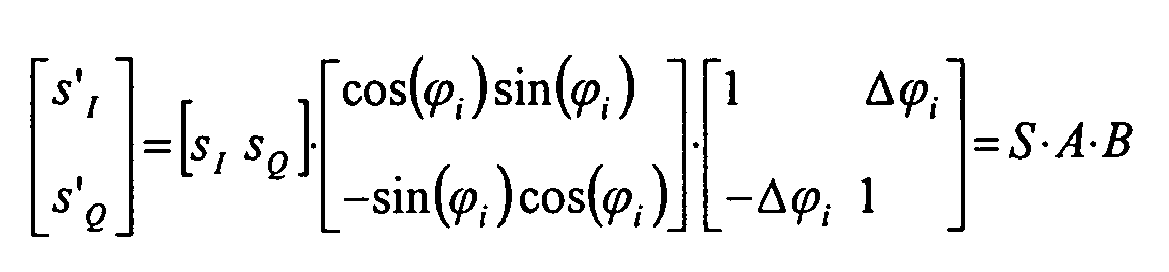
- In this context, a further advantage is obtained if said vector rotation can be described as:


- A further advantage in this context is obtained if said Taylor expansion means performs an additional vector rotation, which can be described as:

wherein Δϕ is an angle error due to the fact that not all bits in said counter means are used for said table look-up. - In this context, a further advantage is obtained, if assuming that Δϕ i is small, the sin ( ), and cos ( ) operations can be approximated with


- The above mentioned problems are also solved with a method for digital frequency conversion, intended for use in a radio system according to
Claim 14. The method comprises the steps: - to perform a frequency synthesis; and
- to perform a table look-up resulting in an approxima tion of a sinusoid; and
- to perform a Taylor expansion in the form of a vector rotation, thereby improving the accuracy of said sinusoid.
- An advantage with this method is that it is possible to reach a high resolution without the disadvantage of increased complexity.
- A further advantage in this context is obtained if said table look-up step comprises the steps:
- to generate an address for said table look-up, using the m most significant bits from a counter means, i.e. the address is m_msb (counter_value)
- to increase said counter_value with a step size S; and
- to repeat the above mentioned steps.
- In this context, a further advantage is obtained if said table comprises M words, and in that the number of bits use for said table look-up will be m = log2(M).
- A further advantage in this context is obtained if the synthesized frequency is

wherein fclk is the used clock frequency. - In this context, a further advantage is obtained if said method also comprises the step:
- to add a signal (PHOFFSET) to adjust the phase of said sinusoid.
- A further advantage in this context is obtained if said table stores the values

- In this context, a further advantage is obtained if said table stores the values

wherein
- A further advantage in this context is obtained if said vector rotation can be described as:


- In this context, a further advantage is obtained if said method also comprises the step:
- to perform an additional vector rotation, which can be described as:

- A further advantage in this context is obtained if assuming that Δϕ i is small, the sin ( ), and cos ( ) operations can be approximated with


- The above mentioned problems are also solved with at least one computer program product, intended for use in a radio system according to
Claim 24. The at least one computer program product is/are directly loadable into the internal memory of at least one digital computer. The at least one computer program product comprises software code portions for performing the steps ofClaim 14 when said said at least one product is/are run on said at least one computer, - An advantage with this/these product/products is/are that it is possible to reach a high resolution without the disadvantage of increased complexity.
- The embodiments of the invention will now be described with reference to the attached drawings, where:
-
- Fig. 1 is a block diagram of a radio architecture utilizing digital frequency conversing according to the prior art;
- Fig. 2 is a block diagram of a system for digital frequency conversion according to the present invention;
- Fig. 3 is a more detailed block diagram of the system disclosed in fig. 2;
- Fig. 4 is a block diagram of the frequency synthesis part of the system disclosed in fig. 3;
- Fig. 5 is a block diagram of the post processing part of the system disclosed in fig. 3;
- Fig. 6 is a flow chart of a method for digital frequency conversion according to the present invention;
- Fig. 7 is a more detailed flow chart of the method according to the present invention; and
- Fig. 8 shows a schematic diagram of some computer program products according to the present invention.
- In fig. 1 there is disclosed a block diagram of a radio architecture utilizing digital frequency conversion according to the prior art. As is apparent in fig. 1, the architecture comprises a numerically controlled
oscillator 100 operable to provide cos ()- and sin () -signals. The architecture also comprises four multiplication means 1021, 1022, 1023, 1024, some of which are connected to said numerically controlledoscillator 100. The four multiplication means 1021 - 1024 are also provided with an input signal, in the form of I- or Q-signals. The architecture also comprises two adding means 1041, 1042 connected to said four multiplication means 1021 - 1024. The architecture also comprises a D/A-converter 106 operable to perform a digital/analogue conversion. A first filter means 108 is connected to said D/A-converter 106. The architecture also comprises a further multiplication means 110 connected to said first filter means 108. Finally, said architecture comprises a second filter means 112 connected to said multiplication means 110, and a to said second filter means 112connected power amplifier 114. The I- and Q-signals are phase shifted 90° in relation to each other. - In Fig. 2 there is disclosed a block diagram of a
system 10 for digital frequency conversion, intended for use in a radio system according to the present invention. Thesystem 10 comprises a frequency synthesis means 12 which receives the I-and Q-signals as input signals. Thesystem 10 also comprises a to said frequency synthesis means 12 connected table look-up means 14. The frequency synthesis means 12 and the table look-up means 14 are booth operable to give an approximation of a sinusoid. Thesystem 10 also comprises a Taylor expansion means 16 connected to said table look-up means 14. The Taylor expansion means 16 is operable to perform a vector rotation, thereby improving the accuracy of said sinusoid. - The vector rotation can be described as:

- The radio system can e.g. be a WLAN system, a GSM system, an UMTS system or a CDMA 2000 system.
- In Fig. 3 there is disclosed a more detailed block diagram of the
system 10 disclosed in fig. 2. In fig. 3 said frequency synthesis means 12 and said table look-up means 14 are illustrated in the form of anumerically control oscillator 30 connected to four multiplication means 321, 322, 323, 324, and two adding means 341, 342 connected to said four multiplication means 321 - 324. The two adding means 341, 342 and said numerically controlledoscillator 30 are connected to said Taylor expansion means 16, which outputs the signals I'' and Q'' . - In Fig. 4 there is disclosed a block diagram of the frequency synthesis part of the
system 10 disclosed in fig. 3. The frequency synthesis part comprises a counter means 20 with a programmable step size S. This means that said counter means 20 is increased with the value S for every update. As is apparent in fig. 4, an addingmeans 24 is connected to said counter means 20, which adding means 24 also is connected to said table look-up means 14. The adding means 24 receives an input signal from said counter means 20, and an input signal (PHOFFSET) which can be used to adjust the phase of the sinusoid from the table look-up means 14. As is apparent in fig. 4, the m most significant bits from the counter means 20 are used as an address to the table look-up means 14, i.e. the address is m _msb (counter_value). The resolution of the counter means 20 is k bits, and k>m. - According to one preferred embodiment of said
system 10, the table look-up means 14 has M entries, wherein the number of bits used for the table look-up will be m = log 2(M): - The synthesized frequency is

- According to one preferred embodiment of said
system 10, the table look-up means 14 stores the values
- According to another preferred embodiment of said
system 10, the table look-up means 14 stores the values

- In Fig. 5, there is disclosed a block diagram of the post processing part of the
system 10 disclosed in fig. 3. The Taylor expansion means 16 comprises a number of multiplication means 261,...,26t, wherein t is an integer. In fig. 5 t is 3. The Taylor expansion means 16 also comprises a number of adding means 281,..., 28P, wherein p is an integer. In fig. 5, p is 3. The addition with "the half range" (the adding means 281) represents a translation from an angle error in the range [0, 2k-m - 1] to the range [-2 k-m-1, 2k-m- 1]. Note that this conversion also can be made by inverting the most significant bit and interpret the result as a signed value in 2's complement representation. The multiplication with "conv-_rad" (the multiplication means 261) is a conversion from the range [-2k-m-1 , 2k-m-1], to the corresponding radians. That is, conv_rad = (2 π)/M. The vector rotation performed by said Taylor expansion means 16 can be described as:
- Here in below follows an explanation of the background to the vector rotation.
- The frequency conversion that we want to perform is in fact a vector rotation that can be described as:


- Since not all bits in the counter means 20 is used for the table look up the resulting values do not represent the actual angle, but instead the closest angle that happens to be stored in the table look-up means 14.
- This angle error Δϕ is proportional to the (k-m)lsb bits in the counter state that not is used for the table look-up. This angle error Δϕ can be corrected if we make an additional rotation operation as described below:

- Assuming that Δϕ; is small we can approximate the sin () and cos () operations with


- This yields the following more simple second rotation operation:

- In fig. 6 there is disclosed a flow chart of a method for digital frequency conversion, intended for use in a radio system according to the present invention. The method begins at
block 50. The method continues, atblock 52, with the step: to perform a frequency synthesis. Thereafter, the method continues, atblock 54 with the step: to perform a table look-up, resulting in an approximation of a sinusoid. The method continues, atblock 56, with the step: to perform a Taylor expansion in the form of a vector rotation, thereby improving the accuracy of said sinusoid. - In Fig. 7 there is disclosed a more detailed flow chart of the method according to the present invention. The method begins at
block 60. The method continues, atblock 62, with the step: to generate an address for said table look-up, using the m most significant bits from the counter means 20 (see fig. 3), i.e. the address is m_msb (counter_value). Thereafter, the method continues atblock 64, with the step: to perform said table look-up with said address, giving the values
block 66, with the step: to perform a first vector rotation, which can be described as:

- Thereafter, the method continues, at
block 68, with the step: to perform a second, additional, vector rotation, which can be described as:
block 70, with the step: to ask the question: Is the counter_value enough? If the answer is affirmative the method is completed, atblock 72. If the answer, on the other hand, is no, the method continues, atblock 74, with the step: to increase the counter_value with the step size S. Thereafter the method step according to block 62 is performed again. - If we assume that Δϕi is small, the sin (), and cos () operations can be approximated with


- In Fig. 8 there is disclosed a schematic diagram of some computer program products, intended for use in a radio system according to the present invention. There is disclosed n different
digital computers 2001, ..., 200n, wherein n is an integer. There is also disclosed n differentcomputer program products 2021, ..., 202n, here showed in the form of compact discs. The differentcomputer program products 2021, ..., 202n are directly loadable into the internal memory of the n differentdigital computers 1001, ..., 100n. Eachcomputer program product 2021, ..., 202n comprises software code portions for performing some or all the steps of Fig. 6 when the product(s) 2021 ..., 202n is/are run on said computer (s) 2001 ..., 200n. Saidcomputer program products 2021, ..., 202n can e. g. be in the form of floppy disks, RAM disks, magnetic tapes, opto magnetical disks or any other suitable products. - The invention is not limited to the embodiments described in the foregoing. It will be obvious that many different modifications are possible within the scope of the following claims.
Claims (24)
- A system (10) for digital frequency conversion, intended for use in a radio system, which system (10) comprises a frequency synthesis means (12) connected to a table look-up means (14), both operable to give an approximation of a sinusoid, characterized in that said system (10) also comprises a to said table look-up means (14) connected Taylor expansion means (16) operable to perform a vector rotation, thereby improving the accuracy of said sinusoid.
- A system (10) for digital frequency conversion according to Claim 1, characterized in that said frequency synthesis means (12) comprises a counter means (20) with a programmable step size (S).
- A system (10) for digital frequency conversion according to Claim 2, characterized in that said counter means (20) is increased with the value S for every update.
- A system (10) for digital frequency conversion according to Claim 2 or 3, characterized in that said table look-up means (14) has M entries, wherein the number of bits used for the table look-up will be m = log2(M).
- A system (10) for digital frequency conversion according to Claim 4, characterized in that the m most significant bits from said counter means (20) are used as an address to said table look-up means (14), i.e. the address is m_msb (counter_value), and in that the resolution of said counter means (20) is k bits, and in that k > m.
- A system (10) for digital frequency conversion according to Claim 4 or 5, characterized in that the synthesized frequency is

- A system (10) for digital frequency conversion according to any one of Claims 2 - 6, characterized in that said system (10) also comprises an adding means (24) connected to said counter means (20) and said table look-up means (14), wherein said adding means (24) receives an input signal from said counter means (20), and an input signal (PHOFFSET), and outputs the address to said table look-up means (14), whereby said input signal (PHOFFSET) is used to adjust the phase of said sinusoid.
- A system (10) for digital frequency conversion according to any one of Claims 1 - 7, characterized in that said table look-up means (14) stores the values

- A system (10) for digital frequency conversion according to any one of Claims 1 - 7, characterized in that said table look-up means (14) stores the values


- A system (10) for digital frequency conversion according to any one of Claims 1 - 0, characterized in that said Taylor expansion means (16) comprises a number of multiplication means (261, ..., 26t), and a number of adding means (281, ..., 28p), wherein p and t are integers.
- A system (10) for digital frequency conversion according to Claim 10, characterized in that said vector rotation can be described as:


- A system (10) for digital frequency conversion according to Claim 11, characterized in that said Taylor expansion means (16) performs an additional vector rotation, which can be described as:

wherein Δ ϕ is an angle error due to the fact that not all bits in said counter means (20) are used for said table look-up. - A system (10) for digital frequency conversion according to Claim 12, characterized in that, assuming that Δϕ i is small, the sin ( ), and cos ( ) operations can be approximated with


- A method for digital frequency conversion, intended for use in a radio system wherein said method comprises the steps:- to perform a frequency synthesis; and- to perform a table look-up resulting in an approximation of a sinusoid; and- to perform a Taylor expansion in the form of a vec tor rotation, thereby improving the accuracy of said sinusoid.
- A method for digital frequency conversion according to Claim 14, characterized in that said table look-up step comprises the steps:- to generate an address for said table look-up, us ing the m most significant bits from a counter means (20), i.e. the address is m_msb (counter_value)- to increase said counter_value with a step size S; and- to repeat the above mentioned steps.
- A method for digital frequency conversion according to Claim 14 or 15, characterized in that said table comprises M words, and in that the number of bits use for said table look-up will be m = log2(M).
- A method for digital frequency conversion according to Claim 16, characterized in that the synthesized frequency is

- A method for digital frequency conversion according to Claim 16 or 17, characterized in that said method also comprises the step:- to add a signal (PHOFFSET) to adjust the phase of said sinusoid.
- A method for digital frequency conversion according to any one of Claims 14 - 18, characterized in that said table stores the values

- A method for digital frequency conversion according to any one of Claims 14 - 18, characterized in that said table stores the values


- A method for digital frequency conversion according to any one of Claims 14 - 20, characterized in that said vector rotation can be described as:


- A method for digital frequency conversion according to Claim 21, characterized in that said method also comprises the step:- to perform an additional vector rotation, which can be described as:wherein Δϕ is an angle error due to the fact that not all bits in said counter means (20) are used for said table look-up.

- A method for digital frequency conversion according to Claim 22, characterized in that, assuming that Δϕ i is small, the sin ( ), and cos ( ) operations can be approximated with


- At least one computer program product (2021, ..., 202n), intended for use in a radio system, where said at least one computer program product (2021, ..., 202n) is/are directly loadable into the internal memory of at least one digital computer (2001, ..., 200n), comprising software code portions for performing the steps of Claim 14 when said at least one product (2021, ..., 202n) is/are run on said at least one computer (2001, ..., 200n) .
Priority Applications (1)
| Application Number | Priority Date | Filing Date | Title |
|---|---|---|---|
| EP04023958A EP1646142A1 (en) | 2004-10-07 | 2004-10-07 | Digital frequency conversion using Taylor approximation |
Applications Claiming Priority (1)
| Application Number | Priority Date | Filing Date | Title |
|---|---|---|---|
| EP04023958A EP1646142A1 (en) | 2004-10-07 | 2004-10-07 | Digital frequency conversion using Taylor approximation |
Publications (1)
| Publication Number | Publication Date |
|---|---|
| EP1646142A1 true EP1646142A1 (en) | 2006-04-12 |
Family
ID=34926894
Family Applications (1)
| Application Number | Title | Priority Date | Filing Date |
|---|---|---|---|
| EP04023958A Withdrawn EP1646142A1 (en) | 2004-10-07 | 2004-10-07 | Digital frequency conversion using Taylor approximation |
Country Status (1)
| Country | Link |
|---|---|
| EP (1) | EP1646142A1 (en) |
Cited By (1)
| Publication number | Priority date | Publication date | Assignee | Title |
|---|---|---|---|---|
| WO2012025796A1 (en) * | 2010-08-27 | 2012-03-01 | M.S. Ramaiah School Of Advanced Studies | Method and apparatus for direct digital synthesis of signals using taylor series expansion |
Citations (2)
| Publication number | Priority date | Publication date | Assignee | Title |
|---|---|---|---|---|
| EP0801465A1 (en) * | 1996-04-12 | 1997-10-15 | Continental Electronics Corporation | Radio transmitter apparatus |
| US20010006543A1 (en) * | 1999-12-24 | 2001-07-05 | Nec Corporation | Phase adjustment technique |
-
2004
- 2004-10-07 EP EP04023958A patent/EP1646142A1/en not_active Withdrawn
Patent Citations (2)
| Publication number | Priority date | Publication date | Assignee | Title |
|---|---|---|---|---|
| EP0801465A1 (en) * | 1996-04-12 | 1997-10-15 | Continental Electronics Corporation | Radio transmitter apparatus |
| US20010006543A1 (en) * | 1999-12-24 | 2001-07-05 | Nec Corporation | Phase adjustment technique |
Non-Patent Citations (1)
| Title |
|---|
| TIERNEY J ET AL: "A digital frequency synthesizer", IEEE TRANSACTIONS ON AUDIO AND ELECTROACOUSTICS, vol. Au-19, no. 1, March 1971 (1971-03-01), USA, pages 48 - 57, XP002321597, ISSN: 0018-9278 * |
Cited By (3)
| Publication number | Priority date | Publication date | Assignee | Title |
|---|---|---|---|---|
| WO2012025796A1 (en) * | 2010-08-27 | 2012-03-01 | M.S. Ramaiah School Of Advanced Studies | Method and apparatus for direct digital synthesis of signals using taylor series expansion |
| US8570203B2 (en) | 2010-08-27 | 2013-10-29 | M.S. Ramaiah School Of Advanced Studies | Method and apparatus for direct digital synthesis of signals using Taylor series expansion |
| US9100044B2 (en) | 2010-08-27 | 2015-08-04 | M.S. Ramaiah School Of Advanced Studies | Method and apparatus for direct digital synthesis of signals using taylor series expansion |
Similar Documents
| Publication | Publication Date | Title |
|---|---|---|
| JP2768778B2 (en) | High resolution phase for sine amplitude conversion | |
| US7440987B1 (en) | 16 bit quadrature direct digital frequency synthesizer using interpolative angle rotation | |
| JP4230665B2 (en) | Multistage frequency division | |
| US6066967A (en) | Phase-coherent frequency synthesis with a DDS circuit | |
| US6587862B1 (en) | Apparatus and method for direct digital frequency synthesis | |
| JPH0241921B2 (en) | ||
| EP1646142A1 (en) | Digital frequency conversion using Taylor approximation | |
| JPS63245129A (en) | Digital/analog converter | |
| JPH0681046B2 (en) | Digital-to-analog converter | |
| TW507424B (en) | Direct digital synthesizer | |
| US20150319519A1 (en) | Digital technique for fm modulation of infrared headphone interface signals | |
| JP2001228930A (en) | Coprocessor for composing signal based on quadratic polynomial sign curve | |
| CN115145353B (en) | High-resolution digital sine wave generator | |
| Ryabov et al. | A direct digital synthesizer of complex signals | |
| KR101658949B1 (en) | Frequency synthesizer using nonlinear digital to analog converter and method thereof | |
| Palomäki et al. | Memory Optimized, High Signal Quality Direct Digital Frequency Synthesizer on an FPGA | |
| US20160161975A1 (en) | Excess-Fours Processing in Direct Digital Synthesizer Implementations | |
| CN107181564B (en) | Signal synthesis method and device based on lookup table | |
| JPH01117423A (en) | Digital analog converter | |
| Sodagar et al. | Second-order parabolic approximation: a new mathematical approximation dedicated to rom-less ddfss | |
| JPS61182097A (en) | Noise reduction device for electronic musical instruments | |
| JPS5811121B2 (en) | digital sine wave synthesizer | |
| ES2271696T3 (en) | WAVE SUPERPOSITION THE CORDIC ALGORITHM. | |
| JPH01103304A (en) | Digital up-conversion structure | |
| Palomäki et al. | Taylor Series Based Method for Generating Digital Sine and Cosine Signals on an FPGA |
Legal Events
| Date | Code | Title | Description |
|---|---|---|---|
| PUAI | Public reference made under article 153(3) epc to a published international application that has entered the european phase |
Free format text: ORIGINAL CODE: 0009012 |
|
| AK | Designated contracting states |
Kind code of ref document: A1 Designated state(s): AT BE BG CH CY CZ DE DK EE ES FI FR GB GR HU IE IT LI LU MC NL PL PT RO SE SI SK TR |
|
| AX | Request for extension of the european patent |
Extension state: AL HR LT LV MK |
|
| AKX | Designation fees paid | ||
| STAA | Information on the status of an ep patent application or granted ep patent |
Free format text: STATUS: THE APPLICATION IS DEEMED TO BE WITHDRAWN |
|
| 18D | Application deemed to be withdrawn |
Effective date: 20061013 |
|
| REG | Reference to a national code |
Ref country code: DE Ref legal event code: 8566 |