EP1645800A2 - System for and method of optically enhancing video and light elements - Google Patents
System for and method of optically enhancing video and light elements Download PDFInfo
- Publication number
- EP1645800A2 EP1645800A2 EP05076942A EP05076942A EP1645800A2 EP 1645800 A2 EP1645800 A2 EP 1645800A2 EP 05076942 A EP05076942 A EP 05076942A EP 05076942 A EP05076942 A EP 05076942A EP 1645800 A2 EP1645800 A2 EP 1645800A2
- Authority
- EP
- European Patent Office
- Prior art keywords
- lighting
- video
- optical element
- array
- elements
- Prior art date
- Legal status (The legal status is an assumption and is not a legal conclusion. Google has not performed a legal analysis and makes no representation as to the accuracy of the status listed.)
- Ceased
Links
Images


Classifications
-
- G—PHYSICS
- G06—COMPUTING; CALCULATING OR COUNTING
- G06F—ELECTRIC DIGITAL DATA PROCESSING
- G06F3/00—Input arrangements for transferring data to be processed into a form capable of being handled by the computer; Output arrangements for transferring data from processing unit to output unit, e.g. interface arrangements
- G06F3/14—Digital output to display device ; Cooperation and interconnection of the display device with other functional units
- G06F3/1423—Digital output to display device ; Cooperation and interconnection of the display device with other functional units controlling a plurality of local displays, e.g. CRT and flat panel display
- G06F3/1431—Digital output to display device ; Cooperation and interconnection of the display device with other functional units controlling a plurality of local displays, e.g. CRT and flat panel display using a single graphics controller
-
- G—PHYSICS
- G06—COMPUTING; CALCULATING OR COUNTING
- G06F—ELECTRIC DIGITAL DATA PROCESSING
- G06F3/00—Input arrangements for transferring data to be processed into a form capable of being handled by the computer; Output arrangements for transferring data from processing unit to output unit, e.g. interface arrangements
- G06F3/14—Digital output to display device ; Cooperation and interconnection of the display device with other functional units
- G06F3/1423—Digital output to display device ; Cooperation and interconnection of the display device with other functional units controlling a plurality of local displays, e.g. CRT and flat panel display
- G06F3/1446—Digital output to display device ; Cooperation and interconnection of the display device with other functional units controlling a plurality of local displays, e.g. CRT and flat panel display display composed of modules, e.g. video walls
-
- G—PHYSICS
- G09—EDUCATION; CRYPTOGRAPHY; DISPLAY; ADVERTISING; SEALS
- G09F—DISPLAYING; ADVERTISING; SIGNS; LABELS OR NAME-PLATES; SEALS
- G09F15/00—Boards, hoardings, pillars, or like structures for notices, placards, posters, or the like
-
- G—PHYSICS
- G09—EDUCATION; CRYPTOGRAPHY; DISPLAY; ADVERTISING; SEALS
- G09F—DISPLAYING; ADVERTISING; SIGNS; LABELS OR NAME-PLATES; SEALS
- G09F19/00—Advertising or display means not otherwise provided for
- G09F19/22—Advertising or display means on roads, walls or similar surfaces, e.g. illuminated
-
- G—PHYSICS
- G09—EDUCATION; CRYPTOGRAPHY; DISPLAY; ADVERTISING; SEALS
- G09F—DISPLAYING; ADVERTISING; SIGNS; LABELS OR NAME-PLATES; SEALS
- G09F27/00—Combined visual and audible advertising or displaying, e.g. for public address
- G09F27/008—Sun shades, shades, hoods or louvres on electronic displays to minimise the effect of direct sun light on the display
-
- G—PHYSICS
- G09—EDUCATION; CRYPTOGRAPHY; DISPLAY; ADVERTISING; SEALS
- G09F—DISPLAYING; ADVERTISING; SIGNS; LABELS OR NAME-PLATES; SEALS
- G09F9/00—Indicating arrangements for variable information in which the information is built-up on a support by selection or combination of individual elements
- G09F9/30—Indicating arrangements for variable information in which the information is built-up on a support by selection or combination of individual elements in which the desired character or characters are formed by combining individual elements
- G09F9/302—Indicating arrangements for variable information in which the information is built-up on a support by selection or combination of individual elements in which the desired character or characters are formed by combining individual elements characterised by the form or geometrical disposition of the individual elements
- G09F9/3026—Video wall, i.e. stackable semiconductor matrix display modules
-
- G—PHYSICS
- G09—EDUCATION; CRYPTOGRAPHY; DISPLAY; ADVERTISING; SEALS
- G09F—DISPLAYING; ADVERTISING; SIGNS; LABELS OR NAME-PLATES; SEALS
- G09F9/00—Indicating arrangements for variable information in which the information is built-up on a support by selection or combination of individual elements
- G09F9/30—Indicating arrangements for variable information in which the information is built-up on a support by selection or combination of individual elements in which the desired character or characters are formed by combining individual elements
- G09F9/33—Indicating arrangements for variable information in which the information is built-up on a support by selection or combination of individual elements in which the desired character or characters are formed by combining individual elements being semiconductor devices, e.g. diodes
- G09F9/335—Indicating arrangements for variable information in which the information is built-up on a support by selection or combination of individual elements in which the desired character or characters are formed by combining individual elements being semiconductor devices, e.g. diodes being organic light emitting diodes [OLED]
-
- G—PHYSICS
- G09—EDUCATION; CRYPTOGRAPHY; DISPLAY; ADVERTISING; SEALS
- G09G—ARRANGEMENTS OR CIRCUITS FOR CONTROL OF INDICATING DEVICES USING STATIC MEANS TO PRESENT VARIABLE INFORMATION
- G09G3/00—Control arrangements or circuits, of interest only in connection with visual indicators other than cathode-ray tubes
- G09G3/20—Control arrangements or circuits, of interest only in connection with visual indicators other than cathode-ray tubes for presentation of an assembly of a number of characters, e.g. a page, by composing the assembly by combination of individual elements arranged in a matrix no fixed position being assigned to or needed to be assigned to the individual characters or partial characters
- G09G3/22—Control arrangements or circuits, of interest only in connection with visual indicators other than cathode-ray tubes for presentation of an assembly of a number of characters, e.g. a page, by composing the assembly by combination of individual elements arranged in a matrix no fixed position being assigned to or needed to be assigned to the individual characters or partial characters using controlled light sources
- G09G3/30—Control arrangements or circuits, of interest only in connection with visual indicators other than cathode-ray tubes for presentation of an assembly of a number of characters, e.g. a page, by composing the assembly by combination of individual elements arranged in a matrix no fixed position being assigned to or needed to be assigned to the individual characters or partial characters using controlled light sources using electroluminescent panels
- G09G3/32—Control arrangements or circuits, of interest only in connection with visual indicators other than cathode-ray tubes for presentation of an assembly of a number of characters, e.g. a page, by composing the assembly by combination of individual elements arranged in a matrix no fixed position being assigned to or needed to be assigned to the individual characters or partial characters using controlled light sources using electroluminescent panels semiconductive, e.g. using light-emitting diodes [LED]
-
- G—PHYSICS
- G09—EDUCATION; CRYPTOGRAPHY; DISPLAY; ADVERTISING; SEALS
- G09G—ARRANGEMENTS OR CIRCUITS FOR CONTROL OF INDICATING DEVICES USING STATIC MEANS TO PRESENT VARIABLE INFORMATION
- G09G3/00—Control arrangements or circuits, of interest only in connection with visual indicators other than cathode-ray tubes
- G09G3/20—Control arrangements or circuits, of interest only in connection with visual indicators other than cathode-ray tubes for presentation of an assembly of a number of characters, e.g. a page, by composing the assembly by combination of individual elements arranged in a matrix no fixed position being assigned to or needed to be assigned to the individual characters or partial characters
- G09G3/34—Control arrangements or circuits, of interest only in connection with visual indicators other than cathode-ray tubes for presentation of an assembly of a number of characters, e.g. a page, by composing the assembly by combination of individual elements arranged in a matrix no fixed position being assigned to or needed to be assigned to the individual characters or partial characters by control of light from an independent source
- G09G3/36—Control arrangements or circuits, of interest only in connection with visual indicators other than cathode-ray tubes for presentation of an assembly of a number of characters, e.g. a page, by composing the assembly by combination of individual elements arranged in a matrix no fixed position being assigned to or needed to be assigned to the individual characters or partial characters by control of light from an independent source using liquid crystals
- G09G3/3611—Control of matrices with row and column drivers
-
- G—PHYSICS
- G09—EDUCATION; CRYPTOGRAPHY; DISPLAY; ADVERTISING; SEALS
- G09G—ARRANGEMENTS OR CIRCUITS FOR CONTROL OF INDICATING DEVICES USING STATIC MEANS TO PRESENT VARIABLE INFORMATION
- G09G5/00—Control arrangements or circuits for visual indicators common to cathode-ray tube indicators and other visual indicators
- G09G5/003—Details of a display terminal, the details relating to the control arrangement of the display terminal and to the interfaces thereto
-
- H—ELECTRICITY
- H04—ELECTRIC COMMUNICATION TECHNIQUE
- H04N—PICTORIAL COMMUNICATION, e.g. TELEVISION
- H04N13/00—Stereoscopic video systems; Multi-view video systems; Details thereof
- H04N13/30—Image reproducers
- H04N13/302—Image reproducers for viewing without the aid of special glasses, i.e. using autostereoscopic displays
- H04N13/305—Image reproducers for viewing without the aid of special glasses, i.e. using autostereoscopic displays using lenticular lenses, e.g. arrangements of cylindrical lenses
-
- H—ELECTRICITY
- H04—ELECTRIC COMMUNICATION TECHNIQUE
- H04N—PICTORIAL COMMUNICATION, e.g. TELEVISION
- H04N5/00—Details of television systems
- H04N5/66—Transforming electric information into light information
- H04N5/70—Circuit details for electroluminescent devices
-
- H—ELECTRICITY
- H04—ELECTRIC COMMUNICATION TECHNIQUE
- H04N—PICTORIAL COMMUNICATION, e.g. TELEVISION
- H04N9/00—Details of colour television systems
- H04N9/12—Picture reproducers
- H04N9/30—Picture reproducers using solid-state colour display devices
-
- H—ELECTRICITY
- H05—ELECTRIC TECHNIQUES NOT OTHERWISE PROVIDED FOR
- H05B—ELECTRIC HEATING; ELECTRIC LIGHT SOURCES NOT OTHERWISE PROVIDED FOR; CIRCUIT ARRANGEMENTS FOR ELECTRIC LIGHT SOURCES, IN GENERAL
- H05B47/00—Circuit arrangements for operating light sources in general, i.e. where the type of light source is not relevant
- H05B47/10—Controlling the light source
- H05B47/175—Controlling the light source by remote control
- H05B47/18—Controlling the light source by remote control via data-bus transmission
-
- G—PHYSICS
- G09—EDUCATION; CRYPTOGRAPHY; DISPLAY; ADVERTISING; SEALS
- G09G—ARRANGEMENTS OR CIRCUITS FOR CONTROL OF INDICATING DEVICES USING STATIC MEANS TO PRESENT VARIABLE INFORMATION
- G09G2300/00—Aspects of the constitution of display devices
- G09G2300/02—Composition of display devices
- G09G2300/026—Video wall, i.e. juxtaposition of a plurality of screens to create a display screen of bigger dimensions
-
- G—PHYSICS
- G09—EDUCATION; CRYPTOGRAPHY; DISPLAY; ADVERTISING; SEALS
- G09G—ARRANGEMENTS OR CIRCUITS FOR CONTROL OF INDICATING DEVICES USING STATIC MEANS TO PRESENT VARIABLE INFORMATION
- G09G2360/00—Aspects of the architecture of display systems
- G09G2360/04—Display device controller operating with a plurality of display units
-
- G—PHYSICS
- G09—EDUCATION; CRYPTOGRAPHY; DISPLAY; ADVERTISING; SEALS
- G09G—ARRANGEMENTS OR CIRCUITS FOR CONTROL OF INDICATING DEVICES USING STATIC MEANS TO PRESENT VARIABLE INFORMATION
- G09G2370/00—Aspects of data communication
- G09G2370/04—Exchange of auxiliary data, i.e. other than image data, between monitor and graphics controller
- G09G2370/042—Exchange of auxiliary data, i.e. other than image data, between monitor and graphics controller for monitor identification
-
- G—PHYSICS
- G09—EDUCATION; CRYPTOGRAPHY; DISPLAY; ADVERTISING; SEALS
- G09G—ARRANGEMENTS OR CIRCUITS FOR CONTROL OF INDICATING DEVICES USING STATIC MEANS TO PRESENT VARIABLE INFORMATION
- G09G2370/00—Aspects of data communication
- G09G2370/04—Exchange of auxiliary data, i.e. other than image data, between monitor and graphics controller
- G09G2370/045—Exchange of auxiliary data, i.e. other than image data, between monitor and graphics controller using multiple communication channels, e.g. parallel and serial
-
- G—PHYSICS
- G09—EDUCATION; CRYPTOGRAPHY; DISPLAY; ADVERTISING; SEALS
- G09G—ARRANGEMENTS OR CIRCUITS FOR CONTROL OF INDICATING DEVICES USING STATIC MEANS TO PRESENT VARIABLE INFORMATION
- G09G3/00—Control arrangements or circuits, of interest only in connection with visual indicators other than cathode-ray tubes
- G09G3/20—Control arrangements or circuits, of interest only in connection with visual indicators other than cathode-ray tubes for presentation of an assembly of a number of characters, e.g. a page, by composing the assembly by combination of individual elements arranged in a matrix no fixed position being assigned to or needed to be assigned to the individual characters or partial characters
- G09G3/2007—Display of intermediate tones
- G09G3/2014—Display of intermediate tones by modulation of the duration of a single pulse during which the logic level remains constant
-
- H—ELECTRICITY
- H04—ELECTRIC COMMUNICATION TECHNIQUE
- H04N—PICTORIAL COMMUNICATION, e.g. TELEVISION
- H04N2213/00—Details of stereoscopic systems
- H04N2213/001—Constructional or mechanical details
-
- H—ELECTRICITY
- H04—ELECTRIC COMMUNICATION TECHNIQUE
- H04N—PICTORIAL COMMUNICATION, e.g. TELEVISION
- H04N9/00—Details of colour television systems
- H04N9/12—Picture reproducers
-
- Y—GENERAL TAGGING OF NEW TECHNOLOGICAL DEVELOPMENTS; GENERAL TAGGING OF CROSS-SECTIONAL TECHNOLOGIES SPANNING OVER SEVERAL SECTIONS OF THE IPC; TECHNICAL SUBJECTS COVERED BY FORMER USPC CROSS-REFERENCE ART COLLECTIONS [XRACs] AND DIGESTS
- Y02—TECHNOLOGIES OR APPLICATIONS FOR MITIGATION OR ADAPTATION AGAINST CLIMATE CHANGE
- Y02B—CLIMATE CHANGE MITIGATION TECHNOLOGIES RELATED TO BUILDINGS, e.g. HOUSING, HOUSE APPLIANCES OR RELATED END-USER APPLICATIONS
- Y02B20/00—Energy efficient lighting technologies, e.g. halogen lamps or gas discharge lamps
- Y02B20/40—Control techniques providing energy savings, e.g. smart controller or presence detection
Definitions
- the present invention relates to a system for and method of optically enhancing video and light elements and, more particularly, to optical elements placed in front of video and light elements to change or enhance their characteristics.
- CRTs Cathode-ray-tubes
- Conventional incandescent lamps, fluorescent lamps, and neon tubes were the traditional lighting elements used to illuminate many large-scale commercial and public signs.
- LEDs light emitting diodes
- Certain types of LEDs can emit radiation in a Lambertian pattern.
- the Lambertian distribution of illumination which does not favor any one direction or orientation over another, is the ideal arrangement for some display uses.
- One example of use for which Lambertian illumination is desired is a scoreboard at a professional sporting event, where fans within the stadium are at all positions relative to the scoreboard - higher, lower, to the left, right, in front of, etc.
- Lambertian light distribution is wasteful, as only persons in front of and slightly below the sign read the information on the sign.
- optical efficiency can be greatly enhanced by the introduction of a light-directing layer in front of the LED or other pixel-based displays, in order to preferentially increase the brightness in a certain direction over other directions, enhance the contrast to accommodate indoor versus outdoor applications, or modify the color to create a desired visual effect.
- both video and lighting effects are desired.
- different lighting elements are generally needed for video versus lighting in order to create the desired effects. What is needed is a means to generate both video and lighting effects by using the same lighting system.
- Three-dimensional images and video are becoming more widely used. To create the more realistic effects and environments demanded by the virtual reality, simulation, and gaming markets, life-like images need to be created and displayed. Until recently, three-dimensional effects were only created by using stereo viewers, red and blue colored glasses, polarizing glasses, or other types of devices. Now, through the use of LEDs and holographic, diffractive or lens array screens, three-dimensional images and video can be viewed by the naked eye.
- optical elements there are many types of optical elements that can be used for an endless number of current and new applications. These optical elements are placed in a beam or path of light in order to change the characteristics of the light passing through the optical elements. Such optical elements may be as simple as a conventional cylindrical or spherical lens.
- optical elements may include Fresnel structures, grating structures, filters, total internal reflection (TIR) structures, nonlinear optical elements, such as Gradient-index (GRIN) lenses, prismatic structures, polarizers, pillow optic formations, fiber optic cables, and other types of optical wave guides, as are well known to those skilled in the art.
- GRIN Gradient-index
- All of these structures receive a light input from a light source and transmit or reflect the light through the structure or element, then permit the light to exit from the structure or element in a somewhat altered state.
- All of these types of optical elements either transmit, reflect, diffract, refract, (partially) absorb or filter out certain wavelengths or polarizations of the light as it exits the structure or element.
- desired enhancements or effects can be created. What is needed is a flexible video and lighting system that can be easily modified to create a desired visual effect or adapted to a specific environment of use, such as indoors or outdoors.
- Said '952 patent application describes a light directing apparatus formed of an LED array that has RGB light emitting diode structures arrayed longitudinally along a substrate to form a plurality of RGB triplet groups and a lenslet array that has a plurality of lenslet structures positioned adjacent to a respective one of the RGB triplet groups.
- the lenslet structures include, for each respective RGB triplet group, a plurality of cylindrical lenses that is indexed to its respective RGB triplet group.
- the cylindrical lenses are longitudinally arrayed in parallel to the respective RGB light emitting diode structures. This arrangement results in greater optical efficiency, because light from the LEDs is preferentially directed in a desired direction where an observer is most likely to be.
- the '952 patent uses cylindrical lenses to direct light from light emitting elements.
- other optical elements may be better suited to changing the viewing angle.
- altering the viewing cone of the emission profile produced by the light emitting elements may also be a desired effect in combination to changing the viewing angle.
- Additional effects may be desired in combination with altering the viewing angle, for example, light diffusion, adding color, or increasing contrast. What is needed is a modular display system that can easily adapt to specific applications and environments, yet remain flexible enough to produce desired video and lighting effects.
- the present invention relates to a video and/or lighting system comprising a lighting module and at least one optical element situated in front of said lighting module that comprises an array of lighting elements, wherein said video and/or lighting system is provided with releasable attaching means for attaching said at least one optical element to said lighting module, for a modular setup of said video and/or lighting system.
- the present invention is a video and/or lighting system that uses solid state, emissive elements, such as LEDs, that, when used in conjunction with optical elements, alters the properties of light that propagate through the optical element and creates desired enhancements or effects.
- solid state, emissive elements such as LEDs
- a modular emissive lighting source can be used for several different applications and in a variety of viewing environments by the user's changing the type or position of the optical element that is placed in front of the emissive lighting source.
- a single system of modular emissive lighting sources can be used to display full-motion video, create magnified, two-dimensional images, create three-dimensional images, or act as a light source by the user' s changing the optical elements.
- Different optical elements can also be used to change the viewing angle or emission profile, enhance the brightness, contrast, and color, or enable the system to be used indoors or outdoors.
- the present invention also relates to a method for optically enhancing a video and/or lighting system wherein use is made of a lighting module and a set of different corresponding optical elements, wherein one or more of said optical elements can be attached in front of said lighting module in a releasable manner, said method comprising the steps of determining the environmental use; determining the desired video and/or lighting effect; choosing an appropriate optical element.out of said set; attaching said appropriate optical element to the lighting module in a releasable manner.
- FIG. 1A illustrates a front view of an exemplary lighting module 100.
- Lighting module 100 contains a 8 x 11 array of emissive lighting elements 110.
- lighting module 100 is not limited in size to 8 x 11 and may be an array of any size.
- Lighting module 100 is designed to be combined with other, similar lighting modules to create a large-scale display.
- Figure 1B illustrates a back view of an exemplary lighting module 100.
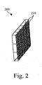
- Figure 2 illustrates a lens array 200 that is formed of an array of rectangular or circular lenses 210, each of which has curved front and/or back faces.
- the faces may be, but are not limited to, planar, spherical, conic aspherical, or polynomial aspherical shapes.
- the lenses are manufactured with a material (e.g., polycarbonate) that exhibits a particular refractive index, which is used to calculate the focal length of each lens.
- Lens array 200 is placed in front of or attached to lighting module 100, an array of lighting modules 100, or the entire video and/or lighting display system.
- Figure 3A illustrates a video and/or lighting system that, according to the invention, is provided with releasable attaching means.
- said releasable attaching means consist of a clicking system 300, in which the two elements are separated.
- Clicking System 300 is used for attaching optical element arrays, such as lens array 200 with shade array 330, to lighting module 100. Shade array 330 blocks sunlight, increases image quality, improves contrast, and is particularly useful in outdoor applications where there might be bright sunlight.
- Clicking system 300 is one embodiment of a means to attach optical element arrays to lighting module 100.
- Other embodiments may include the use of a releasable adhesive, such a releasable glue, to attach an optical element array to lighting element 100.
- Yet a further embodiment may include a clicking mechanism, whereby a latch attaches around lighting module 100.
- Yet another embodiment may be an optical element array attached to lighting module 100 by the use of bolts.
- optical element or an array thereof can be placed in a carrying structure that is provided with releasable attaching means such as said clicking system 300, or that can be attached to said lighting module 100 in a releasable manner by means of bolts or the like for the modular setup of said video and/or lighting system.
- said video and/or lighting system is also provided with means for altering the distance between the lighting elements 110 and said optical element, as this distance is an important parameter for obtaining a desired visual effect.
- Figure 3B illustrates a second front view of clicking system 300, in which the two elements are connected via clicking system 300.
- Figure 3C illustrates a side view of clicking system 300.
- FIG. 3D illustrates Detail B of clicking system 300.
- Clicking system 300 includes lens array 200, which is made up of an array of lenses 340, and, in one embodiment, shade array 330, which includes a latch 310.
- Latch 310 clicks into and attaches to a complementary latch lip 320, which hold lens array 200 onto lighting module 100.
- the distance between lenses 340 and emissive lighting element 110 can be set to a specific distance by use of latch 310 of an appropriate length. Clicking system 300 may also be used to accurately position lenses 340 directly in front of or offset from emissive lighting element 110.
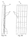
- Figure 4A illustrates a one-to-one lighting system with front optics 400.
- the area between emissive lighting elements 110 and lenses 340 can be filled with air or, more preferably, a material, such as an optical adhesive, which has a refractive index that has been chosen to better optically couple the light from emissive lighting elements 110 into lenses 340. This refractive index match will decrease the light loss.
- optical adhesives include OP-40 High Performance Optical Adhesive, by DYMAX Corporation, and Dow Corning's SYLGARD® 184 Silicone Elastomer.
- non-adhesive optical gels such as Dow Corning's SYLGARD® 527 Silicone dielectric gel
- one-to-one lighting system with front optics 400 is shown with a 5x5 array of emissive lighting elements 110, it is representative of any lighting module 100 of any sized array of emissive lighting elements 110.
- Lens array 200 can be of the same, or similar, size as lighting module 100 and attached to lighting module 100 in a number of ways, such as by clicking system 300, as is shown in Figure 3A.
- lens array 200 may be integrated into a large sheet. This large sheet can have the size of several lighting modules 100 or of the entire display system.
- Figure 4B illustrates a front view of a one-to-one lighting system with front optics 400.
- FIG. 5A illustrates a lighting system with contrast-enhancing front optics 500.
- Lighting system with contrast-enhancing front optics 500 includes emissive lighting elements 110 and lens array 200, made up of an array of lenses 340.
- black matrices 510 are placed on top of lens array 200. The black area between emissive lighting elements 110 will increase viewing contrast for the viewer.
- Figure 5B illustrates a second embodiment of a lighting system with contrast-enhancing front optics 500 in which shade array 330 is placed on top of lens array 200.
- Figure 6A illustrates a one-to-many lighting system with front optics 600.
- Lens array 200 is placed on top of an array of emissive lighting elements 110, in one embodiment, by clicking system 300. There is a plurality of lenses 340 for each emissive lighting element 110. Therefore, the pitch of lens array 200 is much less than the pitch of the array of emissive lighting elements 110. In many instances, it may be more convenient to use a larger lens array 200 that covers several lighting modules 100.
- Figure 6B illustrates Detail B of lens array 200 of one-to-many lighting system with front optics 600.
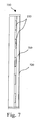
- Figure 7 illustrates a lighting system with thin film front optics 700.
- a supporting transparent structure 710 is placed between emissive lighting elements 110 and a thin film 720.
- Supporting transparent structure 710 provides the necessary space between emissive lighting element 110 and thin film 720 so that the optical properties of thin film 720 create the desired effect.
- Thin film 720 can be, for example, LSD® Light Shaping Diffuser Sheets, by' Physical Optics Corporation.
- supporting transparent structure 710 is placed on top of thin film 720. This protects thin film 720 from damage or from the elements in an outdoor application.
- thin film 720 can be, for example, glued upon supporting transparent structure 710, which is than placed in front of emissive lighting elements 110.
- Thin film 720 can also be used in combination with lens array 200 to produce a combination of desired optical effects. This is possible with both one-to-one lighting system with front optics 400 and one-to-many lighting system with front optics 600.
- thin film 720 is a surface relief diffusion film, which is a thin (e.g., less than 1 mm thick) film whose surface structure is generated in such a way that it will change the emission profile of emissive lighting elements 110 to create circles, squares, snowflakes, ellipses, and other effects. Unlike diffractive optics, thin film 720 has no wavelength dependency. Thin film 720 is designed according to the specifications of emissive lighting elements 110 and the desired optical effect. Additionally, thin film 720 can be a large sheet the size of several lighting modules 100 or the size of the entire display and can be either homogenous or exhibit different optical properties across the film.
- thin film 720 of uniform color is used and placed in front of lighting module 100 in order to change the color of emissive lighting elements 110.
- thin film 720 of a certain density is used and placed in front of lighting modules 100 in order to change the contrast.
- Thin film 720 of this type may also be used in outdoor applications in order to decrease the brightness and enhance the contrast, which improves viewing in bright sunlit environments.
- thin film 720 is a thin plastic or glass sheet with a specific coating, such as a dichroic coating, which is a thin film coating that can act as a short wave pass, long wave pass, bandpass, or notch filter by reflecting unwanted wavelengths back towards the light source.
- a specific coating is a long-pass coating, which is a thin film coating that passes all wavelengths longer than the cut off wavelength and blocks all shorter wavelengths.
- a specific coating is a short-pass coating, which is a thin film coating that passes all wavelengths shorter than the cut off wavelength and blocks all longer wavelengths.
- an infrared (IR) filter could be placed in front of emissive lighting element 110.
- This IR filter reflects the IR radiation present in the ambient illumination and thus prevents the IR radiation from reaching lighting module 100.
- the use of the IR filter a short-pass filter, will increase the thermal stability of the device, since the IR radiation will not be able to heat lighting module 100.
- the image quality is not influenced by the use of such an IR filter.
- Other dichroic coatings can improve visibility and contrast.
- an active element for example a photo-chemical element
- a photo-chemical element can be placed in front of lighting module 100.
- the properties of a photo-chemical element are such that the density changes as a function of the amount of incident sunlight. This can be useful to optimize the contrast for each illumination level when the display is used in an outdoor environment under a variety of sunlight conditions.
- an active element for example a liquid-crystal display (LCD) element
- Lighting element 100 can function as a back light for the LCD panel.
- a desired optical effect can be created, for example polarizing the light from emissive lighting element 110.
- Figure 8 illustrates a lighting system with front optics 800 that is formed of an array of emissive lighting elements 110 and a lens array 200, which is made up of an array of individual lenses 340.
- the optical axis 810 of lens 340 is shown, which is the straight line that is coincident with the axis of symmetry of the surface of lens 340.
- D is the distance between the array of emissive lighting elements 110 and lens array 200.
- the pitch of an optical element is the distance between the centers of two adjacent elements.
- the pitch, P LED of the array of emissive lighting elements 110 is the distance between the centers of two adjacent emissive lighting elements 110.
- the pitch, P lens , of lens array 200 is the distance between the centers of two adjacent lenses 340.
- the pitch of lens array 200 must be much less than the pitch of the array of emissive lighting elements 110, or P lens ⁇ P LED .
- the pitch, P LED , of the array of emissive lighting elements 110 is fixed.
- P lens is designed to avoid or minimize Moiré effects, which those skilled in the art are familiar with.
- P lens is chosen to be as small as possible, in order to minimize Moiré effects. However, it is easier and less expensive to fabricate lens array 200 so that it has a large pitch.
- lens array 200 and the array of emissive lighting elements 110 are considered to be a series of apertures, then they can be considered to be a series of square waves.
- a two-dimensional image will result when the focal lengths of lenses 340 in lens array 200 are the same in both the X axis and the Y axis directions, whereas a three-dimensional image will result when the focal lengths are different in the X axis and the Y axis directions.
- Figure 9 illustrates examples of Fresnel lenses 900.
- the substrate shape is a flat rectangular lens 910 (if cylindrical) or a flat disk lens 920 (if radial).
- One face of the substrate is formed of radial or rectangular facets, which define the profile of Fresnel lens 900, which yields optical power.
- the profile is constructed of radially flat facets (or a series of flat faces if sub-segments are used) (not shown).
- Fresnel lenses 900 can be used instead of spherical lenses and possess the advantage of being thinner and lighter. However, the complex surface structure can lead to imperfections in the virtual image.
- a Fresnel lens array consists of an array of such Fresnel lenses 900.
- the viewing angle of emissive lighting elements 110 can be altered to a desired angle.
- Figure 10 illustrates an example of a gradient-index lens (GRIN) 1000.
- GRIN lens 1000 utilizes a refractive index gradient. The index of refraction is highest in the center of the lens and decreases as distance from the axis increases.
- GRIN lens 1000 focuses light through a precisely controlled radial variation of the lens material's index of refraction, from the optical axis to the edge of the lens.
- GRIN lens 1000 offers an alternative to the often-painstaking craft of polishing curvatures onto glass lenses. Because the index of refraction is gradually varied within the lens material, light rays can be smoothly and continually redirected towards a point of focus. The internal structure of this index gradient can dramatically reduce the need for tightly controlled surface curvatures and results in simple, compact lens geometry.
- a GRIN lens array is formed of an array of GRIN lenses 1000.
- the ability to change the optimum viewing angle of emissive lighting elements 110 or alter the viewing cone of emissive lighting elements 110 is an important feature.
- the distance, D, between lens array 200 and the array of emissive lighting elements 110 is made as small as possible. This ensures that light rays from emissive lighting elements 110 pass only through the lens 340 for which they have been designed, rather than through another lens in lens array 200 that may be adjacent.
- the focal length of lens 340 is chosen in such a way as to create the desired viewing cone.
- emissive lighting element 110 is an organic LED (OLED)
- an array of GRIN lenses 1000 may be preferred. Because of the changing refractive index, the desired optical effects can be created inside GRIN lens 1000.
- GRIN lens 1000 does not require an air gap between it and emissive lighting elements 110, nor between GRIN lens 1000 and the viewer side of the display, which is generally required with other types of lenses, such as Fresnel lens 800. The air gap provides the necessary refractive index change that other types of lenses require to produce the desired optical effect.
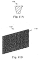
- Figure 11A illustrates a single light pipe 1100.
- Figure 11B illustrates a light pipe array 1120, which is made up of an array of light pipes 1100.
- Light pipe array 1120 can be used to change the fill factor or the viewing angle of lighting module 100.
- light pipe array 1120 can also be used to increase the contrast of a display.
- one-to-one lighting system with front optics 400 is designed such that there is one light pipe 1100 for each emissive lighting element 110. Therefore, the pitch of light pipe array 1120 is equal to the pitch of the array of emissive lighting elements 110. By the user's choosing an appropriate entrance and exit aperture and length of light pipe 1100, the viewing angle of emissive lighting element 110 can be altered to a desired angle.
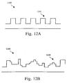
- Figure 12A illustrates an example of a surface relief diffractive optical element 1200.
- One example of the surface of such an optical element is a binary surface relief diffractive optical element 1210.
- Figure 12B illustrates a second example of surface relief diffractive optical element 1200.
- Another example of the surface of such an optical element is a multi-layer surface relief diffractive optical element 1220.
- Diffractive optical elements are generalized diffraction gratings. In contrast to conventional optical systems, which rely on reflection and refraction, diffractive optical elements work by diffracting light.
- the unique property of a diffractive optical element is that the properties of complex optical systems can be encoded in a single element. Diffractive optical elements can perform more than one optical function. For example, they can perform the combination of one or more of filtering, beam division, focusing, etc. Broadly speaking the diffraction process is not affected by the shape of the device. Although thickness is a design parameter, it is measured in microns and has minimal effect on form factor. As a result, diffractive elements are extremely thin and avoid the aperture/weight tradeoffs that exist in classical optical systems.
- Diffractive optics can be based on surface relief structures or alternately thin phase gratings recorded in the bulk medium using holography.
- the surface relief diffractive optical element is created by encoding a relief pattern directly on the surface of the optical component. This pattern is constructed using miniature features. These features may be constructed using techniques such as diamond turning or photolithography.
- the phase of incoming light is manipulated according to the thickness of the features and the index of refraction of the material.
- the DOEs are characterized by high efficiency, design flexibility, light weight and small size. Furthermore, they can be replicated at low cost for mass production.
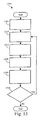
- Figure 13 illustrates an example method 1300 of optically enhancing a video and/or lighting system by using optical elements that are placed in front of the lighting source.
- the method allows a combination of effects to be created by the combination of optical elements.
- the video and/or lighting system can be tailored to different operating environments, for example, indoors or outdoors.
- Method 1300 includes the steps of:
Abstract
Description
- The present invention relates to a system for and method of optically enhancing video and light elements and, more particularly, to optical elements placed in front of video and light elements to change or enhance their characteristics.
- Cathode-ray-tubes (CRTs) and primitive projection systems have long been used to display video and motion pictures. Conventional incandescent lamps, fluorescent lamps, and neon tubes were the traditional lighting elements used to illuminate many large-scale commercial and public signs.
- However, the market is now demanding cheaper and larger displays that have the flexibility to customize display sizes and colors, with image and video capability, and that are easy to install, maintain, and disassemble, especially for use in temporary venues; these are market specifications that are not possible with the older technologies.
- Relatively recent advances in the manufacture of light emitting diodes (LEDs) have made them an attractive light source for many purposes that previously employed incandescent, halogen, or strobe light sources. LED light sources have longer life and higher efficiency, and they are more durable than previously employed light sources.
- Certain types of LEDs can emit radiation in a Lambertian pattern. The Lambertian distribution of illumination, which does not favor any one direction or orientation over another, is the ideal arrangement for some display uses. One example of use for which Lambertian illumination is desired is a scoreboard at a professional sporting event, where fans within the stadium are at all positions relative to the scoreboard - higher, lower, to the left, right, in front of, etc.
- When viewing is predicable, such as billboard signs along a highway, Lambertian light distribution is wasteful, as only persons in front of and slightly below the sign read the information on the sign.
- In certain key applications, optical efficiency can be greatly enhanced by the introduction of a light-directing layer in front of the LED or other pixel-based displays, in order to preferentially increase the brightness in a certain direction over other directions, enhance the contrast to accommodate indoor versus outdoor applications, or modify the color to create a desired visual effect.
- In many applications, for example in entertainment venues, both video and lighting effects are desired. However, different lighting elements are generally needed for video versus lighting in order to create the desired effects. What is needed is a means to generate both video and lighting effects by using the same lighting system.
- Three-dimensional images and video are becoming more widely used. To create the more realistic effects and environments demanded by the virtual reality, simulation, and gaming markets, life-like images need to be created and displayed. Until recently, three-dimensional effects were only created by using stereo viewers, red and blue colored glasses, polarizing glasses, or other types of devices. Now, through the use of LEDs and holographic, diffractive or lens array screens, three-dimensional images and video can be viewed by the naked eye.
- There are many types of optical elements that can be used for an endless number of current and new applications. These optical elements are placed in a beam or path of light in order to change the characteristics of the light passing through the optical elements. Such optical elements may be as simple as a conventional cylindrical or spherical lens.
- Other types of optical elements may include Fresnel structures, grating structures, filters, total internal reflection (TIR) structures, nonlinear optical elements, such as Gradient-index (GRIN) lenses, prismatic structures, polarizers, pillow optic formations, fiber optic cables, and other types of optical wave guides, as are well known to those skilled in the art.
- All of these structures receive a light input from a light source and transmit or reflect the light through the structure or element, then permit the light to exit from the structure or element in a somewhat altered state. All of these types of optical elements either transmit, reflect, diffract, refract, (partially) absorb or filter out certain wavelengths or polarizations of the light as it exits the structure or element. By altering the properties of the light that propagate through the optical element, desired enhancements or effects can be created. What is needed is a flexible video and lighting system that can be easily modified to create a desired visual effect or adapted to a specific environment of use, such as indoors or outdoors.
- An example of an optically enhanced display system is found in reference to U.S. Patent Application No. 20020084952, entitled, "Flat panel color display with enhanced brightness and preferential viewing angles."
- Said '952 patent application describes a light directing apparatus formed of an LED array that has RGB light emitting diode structures arrayed longitudinally along a substrate to form a plurality of RGB triplet groups and a lenslet array that has a plurality of lenslet structures positioned adjacent to a respective one of the RGB triplet groups.
- The lenslet structures include, for each respective RGB triplet group, a plurality of cylindrical lenses that is indexed to its respective RGB triplet group. The cylindrical lenses are longitudinally arrayed in parallel to the respective RGB light emitting diode structures. This arrangement results in greater optical efficiency, because light from the LEDs is preferentially directed in a desired direction where an observer is most likely to be.
- The '952 patent uses cylindrical lenses to direct light from light emitting elements. However, in many applications and environments, other optical elements may be better suited to changing the viewing angle. For example, altering the viewing cone of the emission profile produced by the light emitting elements may also be a desired effect in combination to changing the viewing angle.
- Additional effects may be desired in combination with altering the viewing angle, for example, light diffusion, adding color, or increasing contrast. What is needed is a modular display system that can easily adapt to specific applications and environments, yet remain flexible enough to produce desired video and lighting effects.
- It is therefore an object of the invention to provide a modular display system that can act as both a video and a lighting system.
- It is another object of this invention to provide a flexible lighting system.
- It is yet another object of this invention to provide a video and lighting system that can easily be adapted for indoor or outdoor use.
- It is yet another object of this invention to provide a modular system that can be used for multiple applications.
- It is yet another object of this invention to provide a modular system in front of which a variety of optical elements can be mounted, either independently or in combination, to produce desired video or lighting effects.
- Thereto the present invention relates to a video and/or lighting system comprising a lighting module and at least one optical element situated in front of said lighting module that comprises an array of lighting elements, wherein said video and/or lighting system is provided with releasable attaching means for attaching said at least one optical element to said lighting module, for a modular setup of said video and/or lighting system.
- In particular the present invention is a video and/or lighting system that uses solid state, emissive elements, such as LEDs, that, when used in conjunction with optical elements, alters the properties of light that propagate through the optical element and creates desired enhancements or effects.
- A modular emissive lighting source can be used for several different applications and in a variety of viewing environments by the user's changing the type or position of the optical element that is placed in front of the emissive lighting source.
- For example, a single system of modular emissive lighting sources can be used to display full-motion video, create magnified, two-dimensional images, create three-dimensional images, or act as a light source by the user' s changing the optical elements. Different optical elements can also be used to change the viewing angle or emission profile, enhance the brightness, contrast, and color, or enable the system to be used indoors or outdoors.
- The present invention also relates to a method for optically enhancing a video and/or lighting system wherein use is made of a lighting module and a set of different corresponding optical elements, wherein one or more of said optical elements can be attached in front of said lighting module in a releasable manner, said method comprising the steps of determining the environmental use; determining the desired video and/or lighting effect; choosing an appropriate optical element.out of said set; attaching said appropriate optical element to the lighting module in a releasable manner.
- In order to better explain the characteristics of the invention the following preferred embodiments and method are described as an example only, without being limitative in any way, with reference to the accompanying drawings, in which:
- Figure 1A illustrates a front view of a lighting module in accordance with the invention;
- Figure 1B illustrates a back view of a lighting module in accordance with the invention;
- Figure 2 illustrates a lens array of the present invention;
- Figure 3A illustrates a front view of a clicking system, with components separated, that is used for attaching an optical element array to a lighting module in accordance with the invention;
- Figure 3B illustrates a second front view of a clicking system, with components attached, for attaching an optical element array to a lighting module in accordance with the invention;
- Figure 3C illustrates a side view of a clicking system for attaching an optical element array to a lighting module in accordance with the invention;
- Figure 3D illustrates a detailed view of a clicking system for attaching an optical element array to a lighting module in accordance with the invention;
- Figure 4A illustrates a one-to-one lighting system with front optics in accordance with the invention;
- Figure 4B illustrates a front view of a one-to-one lighting system with front optics in accordance with the invention;
- Figure 5A illustrates a lighting system with contrast-enhancing and viewing angle modifying front optics in accordance with the invention;
- Figure 5B illustrates a second embodiment of a lighting system with contrast-enhancing and viewing angle modifying front optics in accordance with the invention;
- Figure 6A illustrates a one-to-many lighting system with front optics in accordance with the invention;
- Figure 6B illustrates a detailed view of the lens of a one-to-many lighting system with front optics array in accordance with the invention;
- Figure 7 illustrates a lighting system with thin film front optics in accordance with the invention;
- Figure 8 illustrates a lighting system with front optics;
- Figure 9 illustrates examples of Fresnel lenses in accordance with the invention;
- Figure 10 illustrates an example gradient-index lens in accordance with the invention;
- Figure 11A illustrates a light pipe of the present invention;
- Figure 11B illustrates a light pipe array of the present invention;
- Figure 12A illustrates a binary surface relief diffractive optical element;
- Figure 12B illustrates a multi-layer surface relief diffractive optical element;
- Figure 13 is a flow diagram of a method of optically enhancing a video and/or lighting system in accordance with the present invention.
- Figure 1A illustrates a front view of an
exemplary lighting module 100.Lighting module 100 contains a 8 x 11 array ofemissive lighting elements 110. However,lighting module 100 is not limited in size to 8 x 11 and may be an array of any size.Lighting module 100 is designed to be combined with other, similar lighting modules to create a large-scale display. - Figure 1B illustrates a back view of an
exemplary lighting module 100. - Figure 2 illustrates a
lens array 200 that is formed of an array of rectangular orcircular lenses 210, each of which has curved front and/or back faces. The faces may be, but are not limited to, planar, spherical, conic aspherical, or polynomial aspherical shapes. The lenses are manufactured with a material (e.g., polycarbonate) that exhibits a particular refractive index, which is used to calculate the focal length of each lens.Lens array 200 is placed in front of or attached tolighting module 100, an array oflighting modules 100, or the entire video and/or lighting display system. - Figure 3A illustrates a video and/or lighting system that, according to the invention, is provided with releasable attaching means.
- In figure 3A to 3D said releasable attaching means consist of a clicking
system 300, in which the two elements are separated. ClickingSystem 300 is used for attaching optical element arrays, such aslens array 200 withshade array 330, tolighting module 100.Shade array 330 blocks sunlight, increases image quality, improves contrast, and is particularly useful in outdoor applications where there might be bright sunlight. Clickingsystem 300 is one embodiment of a means to attach optical element arrays tolighting module 100. Other embodiments may include the use of a releasable adhesive, such a releasable glue, to attach an optical element array tolighting element 100. Yet a further embodiment may include a clicking mechanism, whereby a latch attaches aroundlighting module 100. Yet another embodiment may be an optical element array attached tolighting module 100 by the use of bolts. - It is clear that the optical element or an array thereof can be placed in a carrying structure that is provided with releasable attaching means such as said clicking
system 300, or that can be attached to saidlighting module 100 in a releasable manner by means of bolts or the like for the modular setup of said video and/or lighting system. - Preferably said video and/or lighting system is also provided with means for altering the distance between the
lighting elements 110 and said optical element, as this distance is an important parameter for obtaining a desired visual effect. - Figure 3B illustrates a second front view of clicking
system 300, in which the two elements are connected via clickingsystem 300. - Figure 3C illustrates a side view of clicking
system 300. - Figure 3D illustrates Detail B of clicking
system 300. Clickingsystem 300 includeslens array 200, which is made up of an array oflenses 340, and, in one embodiment,shade array 330, which includes alatch 310. Latch 310 clicks into and attaches to acomplementary latch lip 320, which holdlens array 200 ontolighting module 100. - The distance between
lenses 340 andemissive lighting element 110 can be set to a specific distance by use oflatch 310 of an appropriate length. Clickingsystem 300 may also be used to accurately positionlenses 340 directly in front of or offset fromemissive lighting element 110. - Figure 4A illustrates a one-to-one lighting system with
front optics 400. There is asingle lens 340 for eachemissive lighting element 110. The area betweenemissive lighting elements 110 andlenses 340 can be filled with air or, more preferably, a material, such as an optical adhesive, which has a refractive index that has been chosen to better optically couple the light fromemissive lighting elements 110 intolenses 340. This refractive index match will decrease the light loss. Examples of optical adhesives include OP-40 High Performance Optical Adhesive, by DYMAX Corporation, and Dow Corning's SYLGARD® 184 Silicone Elastomer. In addition, non-adhesive optical gels, such as Dow Corning's SYLGARD® 527 Silicone dielectric gel, can also be used. Although one-to-one lighting system withfront optics 400 is shown with a 5x5 array ofemissive lighting elements 110, it is representative of anylighting module 100 of any sized array ofemissive lighting elements 110.Lens array 200 can be of the same, or similar, size aslighting module 100 and attached tolighting module 100 in a number of ways, such as by clickingsystem 300, as is shown in Figure 3A. Alternatively,lens array 200 may be integrated into a large sheet. This large sheet can have the size ofseveral lighting modules 100 or of the entire display system. - Figure 4B illustrates a front view of a one-to-one lighting system with
front optics 400. - Figure 5A illustrates a lighting system with contrast-enhancing
front optics 500. Lighting system with contrast-enhancingfront optics 500 includesemissive lighting elements 110 andlens array 200, made up of an array oflenses 340. In one embodiment, on top oflens array 200,black matrices 510 are placed. The black area betweenemissive lighting elements 110 will increase viewing contrast for the viewer. - Figure 5B illustrates a second embodiment of a lighting system with contrast-enhancing
front optics 500 in whichshade array 330 is placed on top oflens array 200. - Figure 6A illustrates a one-to-many lighting system with
front optics 600.Lens array 200 is placed on top of an array ofemissive lighting elements 110, in one embodiment, by clickingsystem 300. There is a plurality oflenses 340 for eachemissive lighting element 110. Therefore, the pitch oflens array 200 is much less than the pitch of the array ofemissive lighting elements 110. In many instances, it may be more convenient to use alarger lens array 200 that coversseveral lighting modules 100. - Figure 6B illustrates Detail B of
lens array 200 of one-to-many lighting system withfront optics 600. - Figure 7 illustrates a lighting system with thin
film front optics 700. In one embodiment, a supportingtransparent structure 710 is placed betweenemissive lighting elements 110 and athin film 720. Supportingtransparent structure 710 provides the necessary space betweenemissive lighting element 110 andthin film 720 so that the optical properties ofthin film 720 create the desired effect.Thin film 720 can be, for example, LSD® Light Shaping Diffuser Sheets, by' Physical Optics Corporation. - In another embodiment, supporting
transparent structure 710 is placed on top ofthin film 720. This protectsthin film 720 from damage or from the elements in an outdoor application. Depending on the type ofthin film 720 used,thin film 720 can be, for example, glued upon supportingtransparent structure 710, which is than placed in front ofemissive lighting elements 110. -
Thin film 720 can also be used in combination withlens array 200 to produce a combination of desired optical effects. This is possible with both one-to-one lighting system withfront optics 400 and one-to-many lighting system withfront optics 600. - In one embodiment,
thin film 720 is a surface relief diffusion film, which is a thin (e.g., less than 1 mm thick) film whose surface structure is generated in such a way that it will change the emission profile ofemissive lighting elements 110 to create circles, squares, snowflakes, ellipses, and other effects. Unlike diffractive optics,thin film 720 has no wavelength dependency.Thin film 720 is designed according to the specifications ofemissive lighting elements 110 and the desired optical effect. Additionally,thin film 720 can be a large sheet the size ofseveral lighting modules 100 or the size of the entire display and can be either homogenous or exhibit different optical properties across the film. - In another embodiment,
thin film 720 of uniform color is used and placed in front oflighting module 100 in order to change the color ofemissive lighting elements 110. - In yet another embodiment,
thin film 720 of a certain density is used and placed in front oflighting modules 100 in order to change the contrast.Thin film 720 of this type may also be used in outdoor applications in order to decrease the brightness and enhance the contrast, which improves viewing in bright sunlit environments. - In yet another embodiment,
thin film 720 is a thin plastic or glass sheet with a specific coating, such as a dichroic coating, which is a thin film coating that can act as a short wave pass, long wave pass, bandpass, or notch filter by reflecting unwanted wavelengths back towards the light source. Another example of a specific coating is a long-pass coating, which is a thin film coating that passes all wavelengths longer than the cut off wavelength and blocks all shorter wavelengths. Yet another example of a specific coating is a short-pass coating, which is a thin film coating that passes all wavelengths shorter than the cut off wavelength and blocks all longer wavelengths. For example, to increase the thermal stability oflighting module 100, an infrared (IR) filter could be placed in front ofemissive lighting element 110. This IR filter reflects the IR radiation present in the ambient illumination and thus prevents the IR radiation from reachinglighting module 100. The use of the IR filter, a short-pass filter, will increase the thermal stability of the device, since the IR radiation will not be able to heatlighting module 100. The image quality is not influenced by the use of such an IR filter. Other dichroic coatings, however, can improve visibility and contrast. - In yet another embodiment, an active element, for example a photo-chemical element, can be placed in front of
lighting module 100. The properties of a photo-chemical element are such that the density changes as a function of the amount of incident sunlight. This can be useful to optimize the contrast for each illumination level when the display is used in an outdoor environment under a variety of sunlight conditions. - In yet another embodiment, an active element, for example a liquid-crystal display (LCD) element, can be placed in front of
lighting module 100.Lighting element 100 can function as a back light for the LCD panel. By appropriately driving the LCD elements, a desired optical effect can be created, for example polarizing the light fromemissive lighting element 110. - Figure 8 illustrates a lighting system with
front optics 800 that is formed of an array ofemissive lighting elements 110 and alens array 200, which is made up of an array ofindividual lenses 340. Theoptical axis 810 oflens 340 is shown, which is the straight line that is coincident with the axis of symmetry of the surface oflens 340. D is the distance between the array ofemissive lighting elements 110 andlens array 200. The pitch of an optical element is the distance between the centers of two adjacent elements. For example, the pitch, PLED, of the array ofemissive lighting elements 110 is the distance between the centers of two adjacentemissive lighting elements 110. The pitch, Plens, oflens array 200 is the distance between the centers of twoadjacent lenses 340. - In order to create a virtual image, the pitch of
lens array 200 must be much less than the pitch of the array ofemissive lighting elements 110, or Plens << PLED. In this embodiment, there areseveral lenses 340 peremissive lighting element 110, as is further illustrated in Figure 5A. The pitch, PLED, of the array ofemissive lighting elements 110 is fixed. Plens is designed to avoid or minimize Moiré effects, which those skilled in the art are familiar with. Plens is chosen to be as small as possible, in order to minimize Moiré effects. However, it is easier and less expensive to fabricatelens array 200 so that it has a large pitch. - If
lens array 200 and the array ofemissive lighting elements 110 are considered to be a series of apertures, then they can be considered to be a series of square waves. The Fourier expansion for a square wave of period P = 2L, frequency f = 1/2L, ω = 2π/2L, and the duty factor d = 2c/2L is given as:
- 2c: signal width
- 2L: period of the square wave = sum of the length of the work interval (= 2c) and the pause interval
- Retaining only the difference terms in a product of two series (i.e., the Fourier expansion of the array of
emissive lighting elements 110 and the Fourier expansion of lens array 200) results in:
where: - LLP: number of
lenses 340 per pixel interval, PLED = PP (mm per pixel interval = pixel pitch) * LLM (number oflenses 340 per unit length) - Integer differences will lead to low beat frequency, whereas half-integer factors will lead to the highest beat frequency. Therefore, the relationship between the pitch of the array of
emissive lighting elements 110 andlens array 200 is chosen to be:
- There is not a unique solution, as m can take on several values while balancing between minimizing the size of
lenses 340, in order to reduce Moiré effects, and maximizing the size oflenses 340, in order to improve the ease of fabrication. - A two-dimensional image will result when the focal lengths of
lenses 340 inlens array 200 are the same in both the X axis and the Y axis directions, whereas a three-dimensional image will result when the focal lengths are different in the X axis and the Y axis directions. - The desired magnification of a virtual image is known and can be described by (when the two-dimensional problem is reduced to a one-dimensional problem, and it is assumed that
lens array 200 is immersed in air):
where: - D: distance between the array of
emissive lighting elements 110 andlens array 200 - f: focal length of
lenses 340 - Θ: angle of observation off the normal
- The distance, D, between the array of
emissive lighting elements 110 andlens array 200 can also be determined by the thickness oflens array 200, Dlens array, and the distance DLED-lens one wants betweenlens array 200 and the array ofemissive lighting elements 110 by the following relationship:
where: - D: distance between the array of
emissive lighting elements 110 and the surface oflens array 200 nearest the array ofemissive lighting elements 110, measured alongoptical axis 810 oflenses 340 inlens array 200 - Dlens array: thickness of
lens array 200, i.e. distance between the surface oflens 340 nearest the array ofemissive lighting elements 110 and the surface oflens 340 furthest from the array ofemissive lighting elements 110, measured alongoptical axis 810 oflens 340 - DLED-lens: distance between the array of
emissive lighting elements 110 and the surface oflens 340 furthest from the array ofemissive lighting elements 110, measured alongoptical axis 810 oflenses 340 inlens array 200 - Knowing the focal length of
lenses 340, the required radius of curvature oflenses 340 can be determined from the following relationship, assuming the thickness oflenses 340 is disregarded:
where: - nlens: index of refraction of
lenses 340 - n1: refractive index of the object medium, i.e. the medium between
emissive lighting elements 110 andlenses 340. The object medium can be air, but it can also be some kind of optical adhesive. - n2: refractive index of the image medium. The image medium will usually be air.
- R1: radius of curvature of the front of
lenses 340 - R2: radius of curvature of the back of
lenses 340 - f1: object effective focal length of the
lenses 340 - f2: image effective focal length of the
lenses 340 - Although the above mathematical equations describe a two-dimensional space, similar relationships exist describing the three-dimensional space.
- Figure 9 illustrates examples of
Fresnel lenses 900. The substrate shape is a flat rectangular lens 910 (if cylindrical) or a flat disk lens 920 (if radial). One face of the substrate is formed of radial or rectangular facets, which define the profile ofFresnel lens 900, which yields optical power. The profile is constructed of radially flat facets (or a series of flat faces if sub-segments are used) (not shown).Fresnel lenses 900 can be used instead of spherical lenses and possess the advantage of being thinner and lighter. However, the complex surface structure can lead to imperfections in the virtual image. A Fresnel lens array consists of an array ofsuch Fresnel lenses 900. - One-to-one lighting system with
front optics 400 can be designed such that eachlens 340 oflens array 200 or eachFresnel lens 900 of an array ofFresnel lenses 900 is matched one-to-one withemissive lighting elements 110. Therefore, the pitch oflens array 200 is equal to the pitch of the array ofemissive lighting elements 110, or PLED = Plens. By the user's choosing the focal length oflenses 340 andpositioning lens array 200 appropriately, the viewing angle ofemissive lighting elements 110 can be altered to a desired angle. The viewing cone is determined by the object and image distances. The relationship between the object distance, the image distance and the focal length is given by:
where: - s2: image distance
- s1: object distance
- f: focal length of lens 340 (it is assumed that
lens array 200 is immersed in air, i.e. f1 = f2 = f) - Figure 10 illustrates an example of a gradient-index lens (GRIN) 1000.
GRIN lens 1000 utilizes a refractive index gradient. The index of refraction is highest in the center of the lens and decreases as distance from the axis increases.GRIN lens 1000 focuses light through a precisely controlled radial variation of the lens material's index of refraction, from the optical axis to the edge of the lens.GRIN lens 1000 offers an alternative to the often-painstaking craft of polishing curvatures onto glass lenses. Because the index of refraction is gradually varied within the lens material, light rays can be smoothly and continually redirected towards a point of focus. The internal structure of this index gradient can dramatically reduce the need for tightly controlled surface curvatures and results in simple, compact lens geometry. A GRIN lens array is formed of an array ofGRIN lenses 1000. - In many applications, the ability to change the optimum viewing angle of
emissive lighting elements 110 or alter the viewing cone ofemissive lighting elements 110 is an important feature. In order to achieve these features, one-to-one lighting system withfront optics 400, is designed such that onelens 340 peremissive lighting element 110 is used. Therefore, the pitch oflens array 200 is equal to the pitch of the array ofemissive lighting elements 110, or PLED = Plens. The distance, D, betweenlens array 200 and the array ofemissive lighting elements 110 is made as small as possible. This ensures that light rays fromemissive lighting elements 110 pass only through thelens 340 for which they have been designed, rather than through another lens inlens array 200 that may be adjacent. The focal length oflens 340 is chosen in such a way as to create the desired viewing cone. - If
emissive lighting element 110 is an organic LED (OLED), an array ofGRIN lenses 1000 may be preferred. Because of the changing refractive index, the desired optical effects can be created insideGRIN lens 1000.GRIN lens 1000 does not require an air gap between it andemissive lighting elements 110, nor betweenGRIN lens 1000 and the viewer side of the display, which is generally required with other types of lenses, such asFresnel lens 800. The air gap provides the necessary refractive index change that other types of lenses require to produce the desired optical effect. - Figure 11A illustrates a
single light pipe 1100. - Figure 11B illustrates a
light pipe array 1120, which is made up of an array oflight pipes 1100.Light pipe array 1120 can be used to change the fill factor or the viewing angle oflighting module 100. In combination with a black matrix 410,light pipe array 1120 can also be used to increase the contrast of a display. - In one embodiment, one-to-one lighting system with
front optics 400 is designed such that there is onelight pipe 1100 for eachemissive lighting element 110. Therefore, the pitch oflight pipe array 1120 is equal to the pitch of the array ofemissive lighting elements 110. By the user's choosing an appropriate entrance and exit aperture and length oflight pipe 1100, the viewing angle ofemissive lighting element 110 can be altered to a desired angle. - Figure 12A illustrates an example of a surface relief diffractive
optical element 1200. One example of the surface of such an optical element is a binary surface relief diffractiveoptical element 1210. - Figure 12B illustrates a second example of surface relief diffractive
optical element 1200. Another example of the surface of such an optical element is a multi-layer surface relief diffractiveoptical element 1220. - Diffractive optical elements (DOE) are generalized diffraction gratings. In contrast to conventional optical systems, which rely on reflection and refraction, diffractive optical elements work by diffracting light. The unique property of a diffractive optical element is that the properties of complex optical systems can be encoded in a single element. Diffractive optical elements can perform more than one optical function. For example, they can perform the combination of one or more of filtering, beam division, focusing, etc. Broadly speaking the diffraction process is not affected by the shape of the device. Although thickness is a design parameter, it is measured in microns and has minimal effect on form factor. As a result, diffractive elements are extremely thin and avoid the aperture/weight tradeoffs that exist in classical optical systems. Their intrinsic thinness and fundamental diffractive properties also allow for unique and extreme form factors not achievable with conventional optics. Diffractive optics can be based on surface relief structures or alternately thin phase gratings recorded in the bulk medium using holography. The surface relief diffractive optical element is created by encoding a relief pattern directly on the surface of the optical component. This pattern is constructed using miniature features. These features may be constructed using techniques such as diamond turning or photolithography. The phase of incoming light is manipulated according to the thickness of the features and the index of refraction of the material. The DOEs are characterized by high efficiency, design flexibility, light weight and small size. Furthermore, they can be replicated at low cost for mass production.
- Figure 13 illustrates an
example method 1300 of optically enhancing a video and/or lighting system by using optical elements that are placed in front of the lighting source. The method allows a combination of effects to be created by the combination of optical elements. The video and/or lighting system can be tailored to different operating environments, for example, indoors or outdoors.Method 1300 includes the steps of: - Step 1305: Determining environment of use
In this step, the environment in which the video and/or lighting system is used is determined. How the system is viewed is also determined. For example, a specific video or lighting system may be used indoors or outdoors, may be viewed from below or from several angles, or may be used in bright sunlight or at night.Method 1300 proceeds to step 1310. - Step 1310: Determining desired video and/or lighting effect
In this step, use of a specific video or lighting effect is determined. The desired effect is a function of the application of the video or lighting display, for example, message notification or entertainment. The desired effect is also a function of the environment in whichlighting module 100 will be used, for example, indoors or outdoors. Video and/or lighting effects may include, but are not limited to, two-dimensional magnification, three-dimensional image, enhanced contrast, adjusted brightness, diffusion, color change, altered viewing angle, altered viewing cone, and modified emission profile.Method 1300 proceeds to step 1315. - Step 1315: Choosing appropriate optical element to create effect
In this step, an optical element is chosen that will best produce the desired video or lighting effect. Factored into the decision is the use of the application, environment, and size, as well as cost and design considerations. Optical element arrays may include, but are not limited to, spherical or rectangular lenses,Fresnel lenses 900,GRIN lenses 1000,light pipes 1100,thin films 720, and diffractiveoptical elements 1200.Method 1300 proceeds to step 1320. - Step 1320: Determining characteristics of optical element array
In this step, characteristics of the optical element array are determined that will best produce the desired video and/or lighting effect appropriate to the application, environment, and intended use of the lighting system. Parameters include, but are not limited to, index of refraction forlenses 340, focal length forlenses 340, pitch oflens array 200, distance betweenlens array 200 and the array ofemissive lighting elements 110, color ofthin film 720, contrast-enhancing elements, such asblack matrices 510 orshade array 330, emission profile ofemissive lighting elements 110, preferred viewing angle, size, and cost. For example, if compact size is an important characteristic of a video and/or lighting system, an optical element array that is thin and small may be used. Alternatively, if cost is a more important consideration than size, larger, cheaper optical element arrays may be used to create the desired effects.Method 1300 proceeds to step 1325. - Step 1325: Determining mechanism for attaching optical element array to lighting module
In this step, how the optical element array is attached to, or placed in front of,lighting module 100 is determined. For example, the video and/or lighting system and the optical element array may be the same size as the display and attached by clickingsystem 300, a fixing mechanism with bolts, or even by placing the optical element array in front of the video and/or lighting system at a fixed distance, without its making contact with the video and/or lighting system. In another embodiment, if the video and/or lighting system is to be used in various applications, an optical element array of the same size as eachlighting module 100 may be used and attached to eachlighting module 100 by clickingsystem 300 or by affixing the optical element array tolighting module 100 by means of an optical adhesive. An optical adhesive has the advantage of improving optical performance by limiting light loss, but its use does make it more difficult to easily construct and teardown temporary video and/or lighting display systems.Method 1300 proceeds to step 1330. - Step 1330: Another video and/or lighting effect?
In this decision step, the user determines whether a combination of multiple video or lighting effects is desired. For some applications and environments, a combination of effects is useful, for example, for adding color while increasing contrast or for diffusing light while changing the viewing cone. A combination of effects can be created by use of a combination of optical elements; for example,thin film 720 can be placed in front oflenses 340. If an additional video and/or lighting effect is desired,method 1300 returns to step 1310. If no additional video and/or lighting effects are desired,method 1300 ends. - The invention is by no means limited to the above described embodiments and method given as an example and represented in the accompanying drawings; on the contrary, such a system and method for optically enhancing a video and/or light elements.
Claims (12)
- A video and/or lighting system comprising a lighting module and at least one optical element situated in front of said lighting module that comprises an array of lighting elements, wherein said video and/or lighting system is provided with releasable attaching means for attaching said at least one optical element to said lighting module, for a modular setup of said video and/or lighting system.
- The video and/or lighting system according to claim 1, wherein said releasable attaching means consist of a clicking system.
- The video and/or lighting system according to claim 2, wherein said clicking system consists of one or more latches projecting from the back of said optical element and of complementary latch lips provided in the front of said lighting module.
- The video and/or lighting system according to claim 1, wherein said optical element consists of an array of lenses that are separated of each other with light blocking elements, and wherein said latches project from said contrast enhancing elements.
- The video and/or lighting system according to claim 1, wherein said optical element is provided in a carrying structure comprising said releasable attaching means.
- The video and/or lighting system according to claim 1, wherein said releasable attaching means comprise bolts.
- The video and/or lighting system according to claim 1, wherein said releasable attaching means consist of an releasable adhesive.
- The video and/or lighting system according to claim 1, wherein a plurality of different corresponding optical elements are available for said lighting module.
- The video and/or lighting system according to claim 1, wherein said optical element is chosen from a group comprising: a conventional cylindrical or spherical lens; Fresnel structures; grating structures; filters; total internal reflection (TIR) structures; nonlinear optical elements, such as Gradient-index (GRIN) lenses; prismatic structures; polarizers; pillow optic formations; fiber optic cables; light pipes; and other types of optical wave guides.
- The video and/or lighting system according to claim 1, wherein said optical element is an array of optical elements.
- A method for optically enhancing a video and/or lighting system wherein use is made of a lighting module and a set of different corresponding optical elements, wherein one or more of said optical elements can be attached in front of said lighting module in a releasable manner, said method comprising the steps of determining the environmental use; determining the desired video and/or lighting effect; choosing an appropriate optical element out of said set; attaching said appropriate optical element to the lighting module in a releasable manner.
- The method according to claim 10, wherein, after attaching said appropriate optical element to said lighting module, another additional desired video and/or lighting effect is determined, in function of which another appropriate optical element is chosen out of said set, which appropriate optical element is subsequently attached in front of said lighting module.
Applications Claiming Priority (1)
| Application Number | Priority Date | Filing Date | Title |
|---|---|---|---|
| US61620004P | 2004-10-07 | 2004-10-07 |
Publications (2)
| Publication Number | Publication Date |
|---|---|
| EP1645800A2 true EP1645800A2 (en) | 2006-04-12 |
| EP1645800A3 EP1645800A3 (en) | 2007-02-28 |
Family
ID=35432005
Family Applications (6)
| Application Number | Title | Priority Date | Filing Date |
|---|---|---|---|
| EP05076951A Withdrawn EP1650731A3 (en) | 2004-10-07 | 2005-08-25 | Display element and mechanical mounting interface used therein |
| EP05076942A Ceased EP1645800A3 (en) | 2004-10-07 | 2005-08-25 | System for and method of optically enhancing video and light elements |
| EP05076949A Ceased EP1650739A3 (en) | 2004-10-07 | 2005-08-25 | Intelligent lighting module, lighting or display module system and method of assembling and configuring such a lighting or display module system |
| EP05076950A Withdrawn EP1646031A3 (en) | 2004-10-07 | 2005-08-25 | Intelligent lighting module and method of operation of such an intelligent lighting module |
| EP05076952A Withdrawn EP1650729A3 (en) | 2004-10-07 | 2005-08-25 | Improved display and corresponding support, emissive lighting display modules and packaging for such display modules |
| EP05076953A Withdrawn EP1667155A1 (en) | 2004-10-07 | 2005-08-25 | Control system and method for controlling lighting and video devices |
Family Applications Before (1)
| Application Number | Title | Priority Date | Filing Date |
|---|---|---|---|
| EP05076951A Withdrawn EP1650731A3 (en) | 2004-10-07 | 2005-08-25 | Display element and mechanical mounting interface used therein |
Family Applications After (4)
| Application Number | Title | Priority Date | Filing Date |
|---|---|---|---|
| EP05076949A Ceased EP1650739A3 (en) | 2004-10-07 | 2005-08-25 | Intelligent lighting module, lighting or display module system and method of assembling and configuring such a lighting or display module system |
| EP05076950A Withdrawn EP1646031A3 (en) | 2004-10-07 | 2005-08-25 | Intelligent lighting module and method of operation of such an intelligent lighting module |
| EP05076952A Withdrawn EP1650729A3 (en) | 2004-10-07 | 2005-08-25 | Improved display and corresponding support, emissive lighting display modules and packaging for such display modules |
| EP05076953A Withdrawn EP1667155A1 (en) | 2004-10-07 | 2005-08-25 | Control system and method for controlling lighting and video devices |
Country Status (4)
| Country | Link |
|---|---|
| US (7) | US20060077669A1 (en) |
| EP (6) | EP1650731A3 (en) |
| JP (6) | JP2006140139A (en) |
| CN (6) | CN1760936A (en) |
Cited By (8)
| Publication number | Priority date | Publication date | Assignee | Title |
|---|---|---|---|---|
| EP2220552A2 (en) * | 2007-12-14 | 2010-08-25 | Samsung Electronics Co., Ltd. | Multifunctional display apparatus |
| WO2010104730A1 (en) * | 2009-03-10 | 2010-09-16 | Lsi Industries, Inc. | 3d screen with modular polarized pixels |
| CN102137530B (en) * | 2010-01-26 | 2013-08-14 | 深圳市尚特光电科技有限公司 | Method for driving household high-power white light light-emitting diode (LED) |
| CN103970042A (en) * | 2014-04-14 | 2014-08-06 | 无锡安东科技有限公司 | Output point driving controller general for LED dot matrix billboard |
| CN104050886A (en) * | 2013-03-13 | 2014-09-17 | 兆光科技有限公司 | Light-emitting diode panels and displays with light baffles and methods and uses thereof |
| CN105321465A (en) * | 2015-10-27 | 2016-02-10 | 刘志海 | LED display screen control system based on FPGA module |
| EP3156991A1 (en) * | 2015-10-12 | 2017-04-19 | Samsung Electronics Co., Ltd. | Optical element of led display apparatus and led display apparatus |
| WO2018227059A1 (en) * | 2017-06-09 | 2018-12-13 | Revolution Display, Llc | Visual-display structure having a metal contrast enhancer, and visual displays made therewith |
Families Citing this family (146)
| Publication number | Priority date | Publication date | Assignee | Title |
|---|---|---|---|---|
| CA2526467C (en) * | 2003-05-20 | 2015-03-03 | Kagutech Ltd. | Digital backplane recursive feedback control |
| US7075992B2 (en) * | 2003-07-11 | 2006-07-11 | Optp Tech Corporation | Digital lighting control system with video input |
| US20060077669A1 (en) * | 2004-10-07 | 2006-04-13 | Robbie Thielemans | Display element and mechanical mounting interface used therein |
| US8624895B2 (en) * | 2005-01-20 | 2014-01-07 | Production Resource Group, Llc | Controls for digital lighting |
| ATE458276T1 (en) * | 2005-04-21 | 2010-03-15 | Fiat Ricerche | CLEAR LED DISPLAY DEVICE |
| US7822958B1 (en) * | 2006-03-10 | 2010-10-26 | Altera Corporation | Booting mechanism for FPGA-based embedded system |
| US7564368B2 (en) * | 2006-05-04 | 2009-07-21 | Zary Segall | Semantic light |
| EP1870802A1 (en) * | 2006-06-22 | 2007-12-26 | Barco NV | Method and device for making user equipment part of a display device |
| US20080002229A1 (en) * | 2006-06-30 | 2008-01-03 | Konica Minolta Systems Laboratory, Inc. | Systems and method for saving memory on screen |
| US20080043003A1 (en) * | 2006-08-17 | 2008-02-21 | Vogsland Robin O | Smart display pixel |
| WO2008043025A2 (en) * | 2006-10-05 | 2008-04-10 | Lumination, Llc | Led backlighting system for cabinet sign |
| DE202006016381U1 (en) * | 2006-10-24 | 2007-01-04 | Annax Anzeigesysteme Gmbh | Seat or berth for use in e.g. train, has display with light matrix from light emitting diodes, where matrix is controllable via interface, and each diode is activated by applying voltage to connections of columns and rows of matrix |
| WO2008070098A2 (en) | 2006-12-04 | 2008-06-12 | Safe Lites, Llc | Method and apparatus for billboard with advertisement including electroluminescent lighting |
| US7868562B2 (en) * | 2006-12-11 | 2011-01-11 | Koninklijke Philips Electronics N.V. | Luminaire control system and method |
| CA2708980C (en) * | 2006-12-11 | 2015-05-05 | Tir Technology Lp | Method and apparatus for digital control of a lighting device |
| EP2092798A4 (en) * | 2006-12-12 | 2014-05-07 | Koninkl Philips Nv | System and method for controlling lighting |
| JP4365867B2 (en) * | 2007-01-11 | 2009-11-18 | 三菱電機株式会社 | Display device |
| GB2460802B (en) * | 2007-03-20 | 2012-09-05 | Prysm Inc | Delivering and displaying advertisment or other application data to display systems |
| EP2315504B1 (en) | 2007-05-09 | 2014-02-26 | Koninklijke Philips N.V. | A method and a system for controlling a lighting system |
| KR20100019530A (en) * | 2007-05-22 | 2010-02-18 | 코닌클리케 필립스 일렉트로닉스 엔.브이. | An ambience lighting system for a display device and a method of operating such ambience lighting system |
| EP2037437A1 (en) * | 2007-09-13 | 2009-03-18 | Dimitijs Volohovs | Configurable large screen display |
| EP2037356A1 (en) * | 2007-09-13 | 2009-03-18 | Dimitijs Volohovs | Large screen display module and method of its use |
| KR101480357B1 (en) * | 2007-11-23 | 2015-01-12 | 삼성디스플레이 주식회사 | Back light unit and liquid crystal display having the same |
| EP2085955A1 (en) * | 2008-02-01 | 2009-08-05 | G-LEC Europe GmbH | Display panel and large-area display system |
| US8782371B2 (en) * | 2008-03-31 | 2014-07-15 | Konica Minolta Laboratory U.S.A., Inc. | Systems and methods for memory management for rasterization |
| DE102008017073A1 (en) * | 2008-04-03 | 2009-10-08 | Zumtobel Lighting Gmbh | Lighting arrangement with several separate lighting units |
| US8525626B2 (en) * | 2008-04-03 | 2013-09-03 | Tait Towers Manufacturing Llc | Interlocking magnetic coupling members |
| US20120235579A1 (en) | 2008-04-14 | 2012-09-20 | Digital Lumens, Incorporated | Methods, apparatus and systems for providing occupancy-based variable lighting |
| US8543249B2 (en) | 2008-04-14 | 2013-09-24 | Digital Lumens Incorporated | Power management unit with modular sensor bus |
| US8373362B2 (en) | 2008-04-14 | 2013-02-12 | Digital Lumens Incorporated | Methods, systems, and apparatus for commissioning an LED lighting fixture with remote reporting |
| US8805550B2 (en) | 2008-04-14 | 2014-08-12 | Digital Lumens Incorporated | Power management unit with power source arbitration |
| US8823277B2 (en) | 2008-04-14 | 2014-09-02 | Digital Lumens Incorporated | Methods, systems, and apparatus for mapping a network of lighting fixtures with light module identification |
| US10539311B2 (en) | 2008-04-14 | 2020-01-21 | Digital Lumens Incorporated | Sensor-based lighting methods, apparatus, and systems |
| US8610377B2 (en) | 2008-04-14 | 2013-12-17 | Digital Lumens, Incorporated | Methods, apparatus, and systems for prediction of lighting module performance |
| US8552664B2 (en) | 2008-04-14 | 2013-10-08 | Digital Lumens Incorporated | Power management unit with ballast interface |
| US8368321B2 (en) | 2008-04-14 | 2013-02-05 | Digital Lumens Incorporated | Power management unit with rules-based power consumption management |
| US8754589B2 (en) | 2008-04-14 | 2014-06-17 | Digtial Lumens Incorporated | Power management unit with temperature protection |
| US8339069B2 (en) | 2008-04-14 | 2012-12-25 | Digital Lumens Incorporated | Power management unit with power metering |
| US8841859B2 (en) | 2008-04-14 | 2014-09-23 | Digital Lumens Incorporated | LED lighting methods, apparatus, and systems including rules-based sensor data logging |
| US8531134B2 (en) | 2008-04-14 | 2013-09-10 | Digital Lumens Incorporated | LED-based lighting methods, apparatus, and systems employing LED light bars, occupancy sensing, local state machine, and time-based tracking of operational modes |
| US8610376B2 (en) | 2008-04-14 | 2013-12-17 | Digital Lumens Incorporated | LED lighting methods, apparatus, and systems including historic sensor data logging |
| US8866408B2 (en) | 2008-04-14 | 2014-10-21 | Digital Lumens Incorporated | Methods, apparatus, and systems for automatic power adjustment based on energy demand information |
| WO2009129232A1 (en) * | 2008-04-14 | 2009-10-22 | Digital Lumens Incorporated | Modular lighting systems |
| US8138690B2 (en) | 2008-04-14 | 2012-03-20 | Digital Lumens Incorporated | LED-based lighting methods, apparatus, and systems employing LED light bars, occupancy sensing, local state machine, and meter circuit |
| US20100014288A1 (en) * | 2008-07-15 | 2010-01-21 | Presence From Innovation, Llc | Retro-fit light stick device and secondary light source or other electrical device for use with walk-in type coolers and other product display units |
| WO2010022104A2 (en) | 2008-08-19 | 2010-02-25 | Plextronics, Inc. | Organic light emitting diode lighting systems |
| WO2010022105A2 (en) * | 2008-08-19 | 2010-02-25 | Plextronics, Inc. | Organic light emitting diode products |
| WO2010022102A2 (en) * | 2008-08-19 | 2010-02-25 | Plextronics, Inc. | User configurable mosaic light emitting apparatus |
| US8414304B2 (en) * | 2008-08-19 | 2013-04-09 | Plextronics, Inc. | Organic light emitting diode lighting devices |
| US20100043263A1 (en) * | 2008-08-20 | 2010-02-25 | Safe Lites, Llc | System and method for modular electroluminescent sign |
| US8817032B2 (en) * | 2008-08-29 | 2014-08-26 | Konica Minolta Laboratory U.S.A., Inc. | Systems and methods for framebuffer management |
| GB0815860D0 (en) * | 2008-09-01 | 2008-10-08 | Oxley Dev Co Ltd | Light emitting device |
| EP2161658A1 (en) * | 2008-09-03 | 2010-03-10 | Bernardo Kastrup | Apparatus and method for generating and displaying visual content |
| US8854680B2 (en) * | 2008-09-11 | 2014-10-07 | Konica Minolta Laboratory U.S.A., Inc. | Systems and methods for optimal memory allocation units |
| US8861014B2 (en) * | 2008-09-30 | 2014-10-14 | Konica Minolta Laboratory U.S.A., Inc. | Systems and methods for optimized printer throughput in a multi-core environment |
| EP2182275A1 (en) * | 2008-10-31 | 2010-05-05 | Osram Gesellschaft mit Beschränkter Haftung | A lighting module and corresponding method |
| FR2939949B1 (en) * | 2008-12-15 | 2012-01-13 | Citiled | COMMUNICATION PANEL PARTICULARLY FOR SPORTS FIELD. |
| WO2010088695A1 (en) * | 2009-02-02 | 2010-08-05 | Apex Technologies, Inc. | Flexible magnetic interconnects |
| US8593135B2 (en) | 2009-04-14 | 2013-11-26 | Digital Lumens Incorporated | Low-cost power measurement circuit |
| US8536802B2 (en) | 2009-04-14 | 2013-09-17 | Digital Lumens Incorporated | LED-based lighting methods, apparatus, and systems employing LED light bars, occupancy sensing, and local state machine |
| US8954170B2 (en) | 2009-04-14 | 2015-02-10 | Digital Lumens Incorporated | Power management unit with multi-input arbitration |
| FR2948482A1 (en) * | 2009-07-21 | 2011-01-28 | Newstep | REMOTE CONTROL DISPLAY DEVICE |
| CN101694762B (en) * | 2009-09-30 | 2011-11-09 | 深圳市雷凌显示技术有限公司 | Display screen box body and LED display screen |
| US8413360B2 (en) * | 2009-11-12 | 2013-04-09 | Jacob Walters | Combined bollard covering and advertising assembly |
| KR101632572B1 (en) * | 2009-11-25 | 2016-07-01 | 삼성전자 주식회사 | Video wall display system |
| WO2011073881A1 (en) * | 2009-12-15 | 2011-06-23 | Koninklijke Philips Electronics N.V. | System and method for associating of lighting scenes to physical objects |
| US9078361B2 (en) | 2010-01-29 | 2015-07-07 | Nederlandse Organisatie Voor Toegepast-Natuurwetenschappelijk Onderzoek Tno | Assembly, component for an assembly and method of manufacturing an assembly |
| CN102822082A (en) * | 2010-04-16 | 2012-12-12 | 三菱电机株式会社 | Lighting device for elevator car |
| US8444275B2 (en) * | 2010-08-12 | 2013-05-21 | Eastman Kodak Company | Light source control for projector with multiple pulse-width modulated light sources |
| TW201213698A (en) * | 2010-09-30 | 2012-04-01 | Young Lighting Technology Corp | Light emitting diode lamp |
| CA3043404A1 (en) | 2010-11-04 | 2012-05-10 | Digital Lumens Incorporated | Method, apparatus, and system for occupancy sensing |
| CN102014565B (en) * | 2010-12-30 | 2013-07-10 | 长安大学 | Intelligent controller and control method of high-power white light LED (light emitting diode) |
| US8912905B2 (en) | 2011-02-28 | 2014-12-16 | Chon Meng Wong | LED lighting system |
| DE102011016360B4 (en) * | 2011-04-07 | 2019-10-02 | Infineon Technologies Ag | Vehicle lighting arrangement, light-emitting circuit driver and method for providing information for determining a lighting condition |
| US8848029B2 (en) | 2011-05-27 | 2014-09-30 | Microsoft Corporation | Optimizing room lighting based on image sensor feedback |
| AU2012332206B2 (en) | 2011-11-03 | 2016-02-04 | Osram Sylvania Inc. | Methods, systems, and apparatus for intelligent lighting |
| EP2777037B1 (en) * | 2011-11-11 | 2016-12-28 | Dolby Laboratories Licensing Corporation | Systems and method for display systems having improved power profiles |
| US20130176743A1 (en) | 2012-01-11 | 2013-07-11 | Sylvan R. Shemitz Designs Incorporated | Luminaire mounting interface |
| US9204519B2 (en) | 2012-02-25 | 2015-12-01 | Pqj Corp | Control system with user interface for lighting fixtures |
| CN106937459B (en) | 2012-03-19 | 2020-06-16 | 数字照明股份有限公司 | Method, system and apparatus for providing variable illumination |
| CN102968931B (en) * | 2012-03-27 | 2014-08-27 | 深圳市康硕展电子有限公司 | Triangular light emitting diode (LED) display screen module and display screen |
| CA2872407C (en) | 2012-05-04 | 2019-06-04 | Lumenpulse Lighting Inc. | Automatic light fixture address system and method |
| US8974077B2 (en) | 2012-07-30 | 2015-03-10 | Ultravision Technologies, Llc | Heat sink for LED light source |
| DE102012109158B4 (en) * | 2012-09-27 | 2017-08-03 | Osram Oled Gmbh | light element |
| US10103297B2 (en) | 2012-12-10 | 2018-10-16 | Daktronics, Inc. | Encapsulation of light-emitting elements on a display module |
| ES2905446T3 (en) * | 2012-12-10 | 2022-04-08 | Daktronics | Encapsulation of light-emitting elements on a display module |
| DE102013102644B4 (en) | 2013-03-14 | 2018-06-07 | Phoenix Contact Gmbh & Co. Kg | Lighting device with two interfaces and control device and lighting system |
| US10210778B2 (en) | 2013-03-16 | 2019-02-19 | Adti Media Llc | Sign construction with sectional sign assemblies and installation kit and method of using same |
| US9047791B2 (en) | 2013-03-16 | 2015-06-02 | Adti Media, Llc. | Sign construction with sectional sign assemblies and installation kit and method of using same |
| US8824125B1 (en) | 2013-03-16 | 2014-09-02 | ADTI Media, LLC | Modular installation and conversion kit for electronic sign structure and method of using same |
| US9852666B2 (en) | 2013-03-16 | 2017-12-26 | Adti Media Llc | Full height sectional sign assembly and installation kit and method of using same |
| US9761157B2 (en) | 2013-03-16 | 2017-09-12 | Adti Media Llc | Customized sectional sign assembly kit and method of using kit for construction and installation of same |
| US8929083B2 (en) | 2013-03-16 | 2015-01-06 | ADIT Media, LLC | Compound structural frame and method of using same for efficient retrofitting |
| EP2992395B1 (en) | 2013-04-30 | 2018-03-07 | Digital Lumens Incorporated | Operating light emitting diodes at low temperature |
| US9117380B2 (en) | 2013-09-06 | 2015-08-25 | Jte L.L.C. | Bollard advertising assembly |
| EP3056067A1 (en) * | 2013-10-07 | 2016-08-17 | Philips Lighting Holding B.V. | Driver unit and driving method for driving a load |
| CA2926260C (en) | 2013-10-10 | 2023-01-24 | Digital Lumens Incorporated | Methods, systems, and apparatus for intelligent lighting |
| GB2519587A (en) | 2013-10-28 | 2015-04-29 | Barco Nv | Tiled Display and method for assembling same |
| US9601061B2 (en) * | 2013-11-01 | 2017-03-21 | Sergio Lara Pereira Monteiro | Method and means to prevent dark lines within the image space of lighted billboards and other public display devices |
| US9218759B2 (en) * | 2013-11-01 | 2015-12-22 | Sergio Lara Pereira Monteiro | Method and means to prevent the formation of visible lines and other image artifacts on illuminated displays |
| US9554438B2 (en) * | 2013-12-11 | 2017-01-24 | Revolution Display, Llc | Lighting integration into video and power stream |
| US9416551B2 (en) | 2013-12-31 | 2016-08-16 | Ultravision Technologies, Llc | Preassembled display systems and methods of installation thereof |
| US9582237B2 (en) | 2013-12-31 | 2017-02-28 | Ultravision Technologies, Llc | Modular display panels with different pitches |
| US9207904B2 (en) | 2013-12-31 | 2015-12-08 | Ultravision Technologies, Llc | Multi-panel display with hot swappable display panels and methods of servicing thereof |
| US9195281B2 (en) | 2013-12-31 | 2015-11-24 | Ultravision Technologies, Llc | System and method for a modular multi-panel display |
| US20150187237A1 (en) | 2013-12-31 | 2015-07-02 | Ultravision Holdings, Llc | System and Method for a Modular Multi-Panel Display |
| WO2015148724A1 (en) | 2014-03-26 | 2015-10-01 | Pqj Corp | System and method for communicating with and for controlling of programmable apparatuses |
| US20150345736A1 (en) * | 2014-05-30 | 2015-12-03 | Marcelo L. Colacilli | Cinema Light with LED Modules and Interchangeable Lenses |
| US10706770B2 (en) | 2014-07-16 | 2020-07-07 | Ultravision Technologies, Llc | Display system having module display panel with circuitry for bidirectional communication |
| CN104409025A (en) * | 2014-12-09 | 2015-03-11 | 京东方科技集团股份有限公司 | Splicing display and display system |
| DE112015005840B4 (en) | 2014-12-29 | 2024-02-29 | Planar Systems, Inc. | Mounting and leveling system for an electronic image display device |
| GB2536191A (en) | 2015-01-05 | 2016-09-14 | Barco Nv | Flexible display tile and method of producing same |
| CN104882747B (en) * | 2015-06-04 | 2017-04-19 | 安徽省通信产业服务有限公司 | Computer network demultiplexer convenient to adjust and install |
| US10847077B2 (en) | 2015-06-05 | 2020-11-24 | Apple Inc. | Emission control apparatuses and methods for a display panel |
| EP3308373A1 (en) | 2015-06-10 | 2018-04-18 | Apple Inc. | Display panel redundancy schemes |
| JP6304159B2 (en) * | 2015-07-23 | 2018-04-04 | コニカミノルタ株式会社 | Image forming apparatus |
| CN105630446B (en) * | 2015-12-23 | 2018-06-12 | 广州市天誉创高电子科技有限公司 | A kind of processing system for video based on FPGA technology |
| EP3378055A1 (en) * | 2015-12-31 | 2018-09-26 | Vstream Digital Media, Ltd | Display arrangement utilizing internal display screen tower surrounded by external display screen sides |
| US9854654B2 (en) | 2016-02-03 | 2017-12-26 | Pqj Corp | System and method of control of a programmable lighting fixture with embedded memory |
| JP6885401B2 (en) * | 2016-05-19 | 2021-06-16 | ソニーグループ株式会社 | Display module |
| CN205961497U (en) * | 2016-05-30 | 2017-02-15 | 深圳市蚂蚁雄兵物联技术有限公司 | Bluetooth ball bubble lamp |
| KR102519930B1 (en) * | 2016-07-07 | 2023-04-11 | 삼성전자주식회사 | Display apparatus |
| KR102431202B1 (en) | 2016-08-23 | 2022-08-11 | 삼성전자주식회사 | Large rollable display apparatus and method for manufacturing the same |
| DE102016118598A1 (en) * | 2016-09-30 | 2018-04-05 | Ma Lighting Technology Gmbh | Lighting console with cooling device |
| KR102529828B1 (en) * | 2016-10-31 | 2023-05-08 | 엘지디스플레이 주식회사 | Display device and multiple display device |
| WO2018106655A1 (en) * | 2016-12-05 | 2018-06-14 | Rensselaer Polytechnic Institute | Methods and devices for transceiving light via a display device |
| CN106448474A (en) * | 2016-12-11 | 2017-02-22 | 北京方瑞博石数字技术有限公司 | Seamless inner spherical display large screen of any arc angle |
| CN106409156A (en) * | 2016-12-11 | 2017-02-15 | 北京方瑞博石数字技术有限公司 | Any-arc-angle excircle-spherical-surface-displaying seamless display screen |
| CN106528030B (en) * | 2016-12-19 | 2019-07-12 | 威创集团股份有限公司 | A kind of combination display methods, apparatus and system |
| JP7288427B2 (en) | 2017-07-11 | 2023-06-07 | コーニング インコーポレイテッド | Tiled display and manufacturing method thereof |
| CN110366293B (en) * | 2017-12-28 | 2021-06-11 | 大道网络(上海)股份有限公司 | Intelligent lighting system and control method of console and console |
| US11094255B2 (en) | 2018-03-29 | 2021-08-17 | Barco N.V. | Driver for LED display |
| CN108469715B (en) * | 2018-04-11 | 2020-03-31 | 郑州胜龙信息技术股份有限公司 | Display method based on pixel light source microarray projection |
| US10480745B1 (en) | 2018-05-24 | 2019-11-19 | Valeo North America, Inc. | Arranged light pipes for automotive lighting systems |
| US11091087B2 (en) | 2018-09-10 | 2021-08-17 | Lumileds Llc | Adaptive headlamp system for vehicles |
| CN110473470B (en) * | 2019-07-10 | 2023-02-21 | 闻泰通讯股份有限公司 | Flexible screen packaging connecting piece and electronic equipment |
| GB201914186D0 (en) | 2019-10-01 | 2019-11-13 | Barco Nv | Driver for LED or OLED display |
| CN110544443A (en) * | 2019-10-14 | 2019-12-06 | 国网山东省电力公司新泰市供电公司 | Intelligent service sign and sign control method |
| KR20210121558A (en) * | 2020-03-30 | 2021-10-08 | 남궁원 | Signboard using flexible LED strip |
| US11892148B2 (en) * | 2020-05-11 | 2024-02-06 | Wangs Alliance Corporation | Fixtures, power and control systems for same |
| LU500366B1 (en) | 2021-06-30 | 2023-01-06 | Barco Nv | Driver circuit for light emitting modules with combined active and passive matrix functionalities |
| LU500364B1 (en) | 2021-06-30 | 2023-01-02 | Barco Nv | Pixel configuration in light emitting modules |
| LU500365B1 (en) | 2021-06-30 | 2023-01-02 | Barco Nv | Improvements in light emitting modules |
| LU500363B1 (en) | 2021-06-30 | 2023-01-02 | Barco Nv | Optical data transmission in light emitting modules |
| LU500367B1 (en) | 2021-06-30 | 2023-01-06 | Barco Nv | Improvements in light emitting modules |
| CN115240570A (en) * | 2022-08-03 | 2022-10-25 | 深圳市宏贯光电科技有限公司 | LED ball-shaped box body and LED ball-shaped display screen |
Citations (3)
| Publication number | Priority date | Publication date | Assignee | Title |
|---|---|---|---|---|
| EP0559124A1 (en) * | 1992-03-04 | 1993-09-08 | K.C.C. Shokai Limited | Illuminating display device for use with a mosaic panel |
| EP0872822A2 (en) * | 1997-04-16 | 1998-10-21 | Siemens Plc | Improvements in or relating to variable message display |
| US5949581A (en) * | 1997-08-12 | 1999-09-07 | Daktronics, Inc. | Display system |
Family Cites Families (87)
| Publication number | Priority date | Publication date | Assignee | Title |
|---|---|---|---|---|
| US2172757A (en) * | 1937-02-03 | 1939-09-12 | Pollock Leopold | Ornament |
| US4234914A (en) * | 1979-03-13 | 1980-11-18 | Stewart-Warner Corporation | Incandescent display system |
| JPS58119681A (en) * | 1982-01-09 | 1983-07-16 | Nippon Denyo Kk | Lamp |
| US4682162A (en) * | 1984-09-14 | 1987-07-21 | Trans-Lux Corporation | Electronic display unit |
| US5329431A (en) * | 1986-07-17 | 1994-07-12 | Vari-Lite, Inc. | Computer controlled lighting system with modular control resources |
| US4935665A (en) * | 1987-12-24 | 1990-06-19 | Mitsubishi Cable Industries Ltd. | Light emitting diode lamp |
| US5043716A (en) * | 1988-07-14 | 1991-08-27 | Adaptive Micro Systems, Inc. | Electronic display with lens matrix |
| JPH02113770U (en) * | 1989-02-28 | 1990-09-12 | ||
| US5036248A (en) * | 1989-03-31 | 1991-07-30 | Ledstar Inc. | Light emitting diode clusters for display signs |
| GB8917055D0 (en) * | 1989-07-26 | 1989-09-13 | Light Years Ahead Ltd | Space lighting fitting |
| US5142461A (en) * | 1989-11-06 | 1992-08-25 | Cynthia Nugent | Decorative light mounting apparatus and method |
| JPH03262172A (en) * | 1990-03-12 | 1991-11-21 | Omron Corp | Optical circuit component assembling jig |
| DK0549679T3 (en) * | 1990-09-20 | 1996-10-14 | Illumination Research Group Pr | viewing System |
| JPH0722001Y2 (en) * | 1991-03-18 | 1995-05-17 | スタンレー電気株式会社 | Light distribution characteristic switching structure for work lights |
| US5174649B1 (en) * | 1991-07-17 | 1998-04-14 | Precision Solar Controls Inc | Led lamp including refractive lens element |
| US5796376A (en) * | 1991-12-18 | 1998-08-18 | Cie Research, Inc. | Electronic display sign |
| JP2562061Y2 (en) * | 1991-12-27 | 1998-02-04 | タキロン株式会社 | Surface light collector for dot matrix light-emitting displays |
| JPH0610976U (en) * | 1992-07-15 | 1994-02-10 | アロー電子工業株式会社 | Display device |
| JPH06102813A (en) * | 1992-09-18 | 1994-04-15 | Fujitsu Ltd | Spacial light modulator and stereoscopic display device |
| JP3334211B2 (en) * | 1993-02-10 | 2002-10-15 | 株式会社日立製作所 | display |
| FR2707223B1 (en) * | 1993-07-07 | 1995-09-29 | Valeo Vision | Improved signaling light with light-emitting diodes. |
| JPH0764208A (en) * | 1993-08-30 | 1995-03-10 | Sanyo Electric Co Ltd | Linear light source |
| EP0728275B1 (en) * | 1993-11-12 | 2005-01-12 | Leviton Manufacturing Co., Inc. | Theatrical lighting control network |
| US5410328A (en) * | 1994-03-28 | 1995-04-25 | Trans-Lux Corporation | Replaceable intelligent pixel module for large-scale LED displays |
| WO1996010244A1 (en) * | 1994-09-27 | 1996-04-04 | Shinsuke Nishida | Display |
| JP2638543B2 (en) * | 1995-02-10 | 1997-08-06 | 日本電気株式会社 | Display module locking mechanism |
| JPH08287719A (en) * | 1995-04-10 | 1996-11-01 | Copal Co Ltd | Light emitting apparatus |
| JPH08304759A (en) * | 1995-05-11 | 1996-11-22 | Rohm Co Ltd | Liquid crystal display device |
| JP3232219B2 (en) * | 1995-08-14 | 2001-11-26 | 株式会社光波 | Dot matrix light emitting display |
| JPH09297543A (en) * | 1996-05-07 | 1997-11-18 | Kouha:Kk | Emissive display device |
| JPH1021475A (en) * | 1996-07-03 | 1998-01-23 | Keiyo:Kk | Portable warning light |
| US5900850A (en) * | 1996-08-28 | 1999-05-04 | Bailey; James Tam | Portable large scale image display system |
| JPH10333631A (en) * | 1997-06-02 | 1998-12-18 | Daichiyuu Denshi:Kk | Expanded display device, and display system using expanded display device |
| US5947769A (en) * | 1997-06-03 | 1999-09-07 | Molex Incorporated | Shielded electrical connector |
| US6016038A (en) * | 1997-08-26 | 2000-01-18 | Color Kinetics, Inc. | Multicolored LED lighting method and apparatus |
| JPH11126047A (en) * | 1997-10-21 | 1999-05-11 | Nichia Chem Ind Ltd | Led display device and its driving method |
| WO1999026131A1 (en) * | 1997-11-13 | 1999-05-27 | Hitachi, Ltd. | Display |
| US6897855B1 (en) * | 1998-02-17 | 2005-05-24 | Sarnoff Corporation | Tiled electronic display structure |
| US5990802A (en) * | 1998-05-18 | 1999-11-23 | Smartlite Communications, Inc. | Modular LED messaging sign panel and display system |
| JP3342665B2 (en) * | 1998-06-17 | 2002-11-11 | 株式会社カスト | Display device |
| US6219099B1 (en) * | 1998-09-23 | 2001-04-17 | Honeywell International Inc. | Method and apparatus for calibrating a display using an array of cameras |
| US6065854A (en) * | 1999-01-07 | 2000-05-23 | Integrated Systems Engineering Inc. | LED modular display system |
| JP2000214820A (en) * | 1999-01-27 | 2000-08-04 | Futaba Corp | Image displaying method and drive circuit for display device |
| US6314669B1 (en) | 1999-02-09 | 2001-11-13 | Daktronics, Inc. | Sectional display system |
| US6498592B1 (en) * | 1999-02-16 | 2002-12-24 | Sarnoff Corp. | Display tile structure using organic light emitting materials |
| DE19907319B4 (en) | 1999-02-20 | 2005-04-28 | Krone Gmbh | Snubber |
| DE19908040A1 (en) * | 1999-02-24 | 2000-08-31 | Diehl Stiftung & Co | Device for illuminating rooms, bodies or surfaces |
| JP4017057B2 (en) * | 1999-04-27 | 2007-12-05 | 株式会社日立プラズマパテントライセンシング | Driving method of plasma display panel |
| BE1012634A3 (en) * | 1999-04-28 | 2001-01-09 | Barco Nv | Method for displaying images on a display device, and display device used for this purpose. |
| US7145469B2 (en) * | 1999-05-04 | 2006-12-05 | Intellimats, Llc | Display system for use on horizontal or non-horizontal surfaces |
| US6605907B2 (en) * | 1999-09-10 | 2003-08-12 | Richard S. Belliveau | Method, apparatus and system for image projection lighting |
| US6331756B1 (en) * | 1999-09-10 | 2001-12-18 | Richard S. Belliveau | Method and apparatus for digital communications with multiparameter light fixtures |
| DE19951348A1 (en) * | 1999-10-25 | 2001-05-31 | Dambach Werke Gmbh | Display device has display modules arranged in at least one column and/or at least one row with separate module housing accommodated in bearer structure, common control unit and supply |
| US6672748B2 (en) * | 2000-01-05 | 2004-01-06 | Eric Dean Baldwin | Back lighted display unit |
| KR100339476B1 (en) * | 2000-01-07 | 2002-06-01 | 구자홍 | A foldable case emitting a light backward |
| WO2001063977A1 (en) * | 2000-02-23 | 2001-08-30 | Production Solutions, Inc. | Sequential control circuit |
| JP2001282144A (en) * | 2000-03-31 | 2001-10-12 | Sony Corp | Video display device and video display unit for the same |
| US6394626B1 (en) * | 2000-04-11 | 2002-05-28 | Lumileds Lighting, U.S., Llc | Flexible light track for signage |
| US6364507B1 (en) * | 2000-05-01 | 2002-04-02 | Formosa Industrial Computing Inc. | Waterproof LED display |
| TW582015B (en) * | 2000-06-30 | 2004-04-01 | Nichia Corp | Display unit communication system, communication method, display unit, communication circuit and terminal adapter |
| US6402336B1 (en) * | 2000-09-02 | 2002-06-11 | Donald Reese | Lights in a blanket |
| JP2004511078A (en) * | 2000-10-13 | 2004-04-08 | フラット ホワイト ライティング ピーティーワイ リミテッド | Lighting system |
| WO2002040921A2 (en) * | 2000-10-23 | 2002-05-23 | Color Kinetics Incorporated | Systems and methods for digital entertainement |
| US6732460B2 (en) * | 2000-11-28 | 2004-05-11 | Bill Blakeslee | Illuminated display assembly |
| JP4399999B2 (en) * | 2001-03-23 | 2010-01-20 | パナソニック電工株式会社 | Lighting control device, lighting system |
| US6955449B2 (en) * | 2001-04-13 | 2005-10-18 | Gelcore Llc | LED symbol signal |
| JP2002368290A (en) * | 2001-06-13 | 2002-12-20 | Okaya Electric Ind Co Ltd | Led display |
| JP2003086384A (en) * | 2001-06-28 | 2003-03-20 | Matsushita Electric Ind Co Ltd | Method of providing illumination service, illumination device, recording medium and reproduction device |
| JP3760900B2 (en) * | 2001-09-06 | 2006-03-29 | セイコーエプソン株式会社 | Light guiding device, electro-optical device, and electronic apparatus |
| US6566824B2 (en) * | 2001-10-16 | 2003-05-20 | Teledyne Lighting And Display Products, Inc. | Flexible lighting segment |
| JP3984023B2 (en) * | 2001-11-02 | 2007-09-26 | 株式会社小糸製作所 | Vehicle lamp |
| JP3599022B2 (en) * | 2002-01-10 | 2004-12-08 | カシオ計算機株式会社 | Liquid crystal display |
| TW591267B (en) * | 2002-01-11 | 2004-06-11 | Chi Mei Optoelectronics Corp | A liquid crystal display device |
| EP1496488A1 (en) * | 2002-04-17 | 2005-01-12 | Kabushiki Kaisha Box | Surface light emitting device |
| JP4159816B2 (en) * | 2002-07-02 | 2008-10-01 | 松下電器産業株式会社 | Display device |
| US6812653B2 (en) * | 2002-07-26 | 2004-11-02 | Richard S. Bellivean | Method and apparatus for controlling images with image projection lighting devices |
| DE10245933B4 (en) * | 2002-09-30 | 2013-10-10 | Osram Opto Semiconductors Gmbh | Device for generating a bundled luminous flux |
| JP5261858B2 (en) * | 2002-10-01 | 2013-08-14 | 日亜化学工業株式会社 | COMMUNICATION CONTROL DEVICE, ITS DRIVE METHOD, AND LED DISPLAY |
| CN100585274C (en) * | 2002-10-25 | 2010-01-27 | 森山产业株式会社 | Light emitting module |
| US7063449B2 (en) * | 2002-11-21 | 2006-06-20 | Element Labs, Inc. | Light emitting diode (LED) picture element |
| US6719433B1 (en) * | 2003-01-02 | 2004-04-13 | Richard S. Belliveau | Lighting system incorporating programmable video feedback lighting devices and camera image rotation |
| ATE394769T1 (en) * | 2003-05-23 | 2008-05-15 | Barco Nv | METHOD FOR DISPLAYING IMAGES ON A LARGE SCREEN DISPLAY MADE OF ORGANIC LIGHT-LIGHT DIODES AND THE DISPLAY USED FOR THIS |
| US7123211B2 (en) * | 2003-07-31 | 2006-10-17 | Hewlett-Packard Development Company, L.P. | Surround-vision display system |
| EP1513060A1 (en) * | 2003-09-08 | 2005-03-09 | Barco N.V. | Large-area display system, modular unit used therein and method of operating the display |
| EP1515297B1 (en) * | 2003-09-08 | 2013-03-06 | Barco, naamloze vennootschap. | A display pixel module for use in a configurable large-screen display application and display with such pixel modules |
| US20050134526A1 (en) * | 2003-12-23 | 2005-06-23 | Patrick Willem | Configurable tiled emissive display |
| US20060077669A1 (en) * | 2004-10-07 | 2006-04-13 | Robbie Thielemans | Display element and mechanical mounting interface used therein |
-
2005
- 2005-02-08 US US11/052,058 patent/US20060077669A1/en not_active Abandoned
- 2005-02-08 US US11/052,057 patent/US7450085B2/en not_active Expired - Fee Related
- 2005-02-08 US US11/052,054 patent/US20060075666A1/en not_active Abandoned
- 2005-02-08 US US11/052,056 patent/US20060077192A1/en not_active Abandoned
- 2005-02-08 US US11/052,053 patent/US7205729B2/en not_active Expired - Fee Related
- 2005-02-08 US US11/052,055 patent/US20060077307A1/en not_active Abandoned
- 2005-08-25 EP EP05076951A patent/EP1650731A3/en not_active Withdrawn
- 2005-08-25 EP EP05076942A patent/EP1645800A3/en not_active Ceased
- 2005-08-25 EP EP05076949A patent/EP1650739A3/en not_active Ceased
- 2005-08-25 EP EP05076950A patent/EP1646031A3/en not_active Withdrawn
- 2005-08-25 EP EP05076952A patent/EP1650729A3/en not_active Withdrawn
- 2005-08-25 EP EP05076953A patent/EP1667155A1/en not_active Withdrawn
- 2005-09-28 CN CNA2005101071791A patent/CN1760936A/en active Pending
- 2005-09-28 CN CNA2005101071819A patent/CN1770944A/en active Pending
- 2005-09-28 CN CNA2005101071772A patent/CN1780516A/en active Pending
- 2005-09-28 CN CNA2005101071823A patent/CN1760752A/en active Pending
- 2005-09-28 CN CNA2005101071787A patent/CN1770943A/en active Pending
- 2005-09-28 CN CNA2005101071804A patent/CN1763805A/en active Pending
- 2005-10-07 JP JP2005294615A patent/JP2006140139A/en active Pending
- 2005-10-07 JP JP2005294784A patent/JP2006106762A/en active Pending
- 2005-10-07 JP JP2005295755A patent/JP2006108110A/en active Pending
- 2005-10-07 JP JP2005295720A patent/JP2006106764A/en active Pending
- 2005-10-07 JP JP2005295568A patent/JP2006106763A/en active Pending
- 2005-10-07 JP JP2005294708A patent/JP2006163364A/en active Pending
-
2007
- 2007-07-20 US US11/878,006 patent/US20070263394A1/en not_active Abandoned
Patent Citations (3)
| Publication number | Priority date | Publication date | Assignee | Title |
|---|---|---|---|---|
| EP0559124A1 (en) * | 1992-03-04 | 1993-09-08 | K.C.C. Shokai Limited | Illuminating display device for use with a mosaic panel |
| EP0872822A2 (en) * | 1997-04-16 | 1998-10-21 | Siemens Plc | Improvements in or relating to variable message display |
| US5949581A (en) * | 1997-08-12 | 1999-09-07 | Daktronics, Inc. | Display system |
Cited By (13)
| Publication number | Priority date | Publication date | Assignee | Title |
|---|---|---|---|---|
| EP2220552A2 (en) * | 2007-12-14 | 2010-08-25 | Samsung Electronics Co., Ltd. | Multifunctional display apparatus |
| EP2220552A4 (en) * | 2007-12-14 | 2011-09-07 | Samsung Electronics Co Ltd | Multifunctional display apparatus |
| WO2010104730A1 (en) * | 2009-03-10 | 2010-09-16 | Lsi Industries, Inc. | 3d screen with modular polarized pixels |
| CN102137530B (en) * | 2010-01-26 | 2013-08-14 | 深圳市尚特光电科技有限公司 | Method for driving household high-power white light light-emitting diode (LED) |
| US20140268738A1 (en) * | 2013-03-13 | 2014-09-18 | Lighthouse Technologies (Huizhou) Limited | Light-emitting diode panels and displays with light baffles and methods and uses thereof |
| CN104050886A (en) * | 2013-03-13 | 2014-09-17 | 兆光科技有限公司 | Light-emitting diode panels and displays with light baffles and methods and uses thereof |
| US9052085B2 (en) * | 2013-03-13 | 2015-06-09 | Lighthouse Technologies Limited | Light-emitting diode panels and displays with light baffles and methods and uses thereof |
| CN103970042A (en) * | 2014-04-14 | 2014-08-06 | 无锡安东科技有限公司 | Output point driving controller general for LED dot matrix billboard |
| CN103970042B (en) * | 2014-04-14 | 2017-02-01 | 无锡安东科技有限公司 | Output point driving controller general for LED dot matrix billboard |
| EP3156991A1 (en) * | 2015-10-12 | 2017-04-19 | Samsung Electronics Co., Ltd. | Optical element of led display apparatus and led display apparatus |
| CN105321465A (en) * | 2015-10-27 | 2016-02-10 | 刘志海 | LED display screen control system based on FPGA module |
| WO2018227059A1 (en) * | 2017-06-09 | 2018-12-13 | Revolution Display, Llc | Visual-display structure having a metal contrast enhancer, and visual displays made therewith |
| US10333109B2 (en) | 2017-06-09 | 2019-06-25 | Production Resource Group, L.L.C. | Visual-display structure having a metal contrast enhancer, and visual displays made therewith |
Also Published As
| Publication number | Publication date |
|---|---|
| CN1760936A (en) | 2006-04-19 |
| EP1646031A3 (en) | 2006-09-13 |
| EP1645800A3 (en) | 2007-02-28 |
| US20060077669A1 (en) | 2006-04-13 |
| US20060077193A1 (en) | 2006-04-13 |
| US20060077307A1 (en) | 2006-04-13 |
| JP2006108110A (en) | 2006-04-20 |
| CN1770943A (en) | 2006-05-10 |
| JP2006106762A (en) | 2006-04-20 |
| EP1650731A3 (en) | 2007-11-28 |
| US20060077192A1 (en) | 2006-04-13 |
| US20070263394A1 (en) | 2007-11-15 |
| JP2006106764A (en) | 2006-04-20 |
| US20060075666A1 (en) | 2006-04-13 |
| JP2006140139A (en) | 2006-06-01 |
| EP1650739A3 (en) | 2006-09-13 |
| EP1667155A1 (en) | 2006-06-07 |
| CN1763805A (en) | 2006-04-26 |
| CN1760752A (en) | 2006-04-19 |
| EP1650729A3 (en) | 2007-11-28 |
| CN1780516A (en) | 2006-05-31 |
| US7205729B2 (en) | 2007-04-17 |
| EP1650739A2 (en) | 2006-04-26 |
| US7450085B2 (en) | 2008-11-11 |
| JP2006106763A (en) | 2006-04-20 |
| CN1770944A (en) | 2006-05-10 |
| EP1650729A2 (en) | 2006-04-26 |
| US20060076906A1 (en) | 2006-04-13 |
| JP2006163364A (en) | 2006-06-22 |
| EP1650731A2 (en) | 2006-04-26 |
| EP1646031A2 (en) | 2006-04-12 |
Similar Documents
| Publication | Publication Date | Title |
|---|---|---|
| EP1645800A2 (en) | System for and method of optically enhancing video and light elements | |
| US4952023A (en) | Internally illuminated retroreflective sign | |
| US7113342B2 (en) | Composite structure for light diffusion | |
| TWI623779B (en) | Grating-based backlight, electronic display and method employing reflective grating islands | |
| US7824091B2 (en) | Backlight arrangement | |
| US9000661B2 (en) | Energy efficient light source comprising photoluminescent material and a selective mirror | |
| KR101269672B1 (en) | Optical film having enhanced optical performance and back light unit comprising the same | |
| US20090097229A1 (en) | Light management films, back light units, and related structures | |
| CN114488678B (en) | Curved surface screen, microstructure setting method thereof and projection system | |
| CN101095077A (en) | Optical film having a structured surface with concave pyramid-shaped structures | |
| US6102545A (en) | Liquid crystal display unit | |
| CN108398735B (en) | Directional imaging device, method and application | |
| TW201423165A (en) | Tandem array lens sheet | |
| CN100492163C (en) | Reflection type screen | |
| WO2001088576A1 (en) | Micro-display driven tiled electro-optic display apparatus | |
| CN103502849A (en) | Microlens array sheet and backlight unit including same | |
| JPH07120743A (en) | Method for mounting microlens array sheet | |
| US7421180B2 (en) | Light guide apparatus for use in rear projection display environments | |
| CN212256002U (en) | Head-up display device and motor vehicle | |
| CN210666314U (en) | Light control device, image source, projection curtain, projection system and imaging system | |
| US5818627A (en) | Devices with micro-mirrors and micro-filters for selecting colors and images | |
| TWI611216B (en) | 2d/3d mode-switchable electronic display and method with dual layer backlight | |
| JPS6111782A (en) | Image display | |
| KR20080089909A (en) | Back light unit and display device having it | |
| WO2019017443A1 (en) | Image display device |
Legal Events
| Date | Code | Title | Description |
|---|---|---|---|
| PUAI | Public reference made under article 153(3) epc to a published international application that has entered the european phase |
Free format text: ORIGINAL CODE: 0009012 |
|
| AK | Designated contracting states |
Kind code of ref document: A2 Designated state(s): AT BE BG CH CY CZ DE DK EE ES FI FR GB GR HU IE IS IT LI LT LU LV MC NL PL PT RO SE SI SK TR |
|
| AX | Request for extension of the european patent |
Extension state: AL BA HR MK YU |
|
| PUAL | Search report despatched |
Free format text: ORIGINAL CODE: 0009013 |
|
| AK | Designated contracting states |
Kind code of ref document: A3 Designated state(s): AT BE BG CH CY CZ DE DK EE ES FI FR GB GR HU IE IS IT LI LT LU LV MC NL PL PT RO SE SI SK TR |
|
| AX | Request for extension of the european patent |
Extension state: AL BA HR MK YU |
|
| 17P | Request for examination filed |
Effective date: 20070717 |
|
| AKX | Designation fees paid |
Designated state(s): AT BE BG CH CY CZ DE DK EE ES FI FR GB GR HU IE IS IT LI LT LU LV MC NL PL PT RO SE SI SK TR |
|
| 17Q | First examination report despatched |
Effective date: 20071012 |
|
| STAA | Information on the status of an ep patent application or granted ep patent |
Free format text: STATUS: THE APPLICATION HAS BEEN REFUSED |
|
| 18R | Application refused |
Effective date: 20090630 |