EP1645773A1 - Hydraulic antivibration device for vehicles and process for manufacturing such a device - Google Patents
Hydraulic antivibration device for vehicles and process for manufacturing such a device Download PDFInfo
- Publication number
- EP1645773A1 EP1645773A1 EP05292104A EP05292104A EP1645773A1 EP 1645773 A1 EP1645773 A1 EP 1645773A1 EP 05292104 A EP05292104 A EP 05292104A EP 05292104 A EP05292104 A EP 05292104A EP 1645773 A1 EP1645773 A1 EP 1645773A1
- Authority
- EP
- European Patent Office
- Prior art keywords
- chambers
- armature
- frame
- window frame
- longitudinal axis
- Prior art date
- Legal status (The legal status is an assumption and is not a legal conclusion. Google has not performed a legal analysis and makes no representation as to the accuracy of the status listed.)
- Granted
Links
Images


Classifications
-
- F—MECHANICAL ENGINEERING; LIGHTING; HEATING; WEAPONS; BLASTING
- F16—ENGINEERING ELEMENTS AND UNITS; GENERAL MEASURES FOR PRODUCING AND MAINTAINING EFFECTIVE FUNCTIONING OF MACHINES OR INSTALLATIONS; THERMAL INSULATION IN GENERAL
- F16F—SPRINGS; SHOCK-ABSORBERS; MEANS FOR DAMPING VIBRATION
- F16F13/00—Units comprising springs of the non-fluid type as well as vibration-dampers, shock-absorbers, or fluid springs
- F16F13/04—Units comprising springs of the non-fluid type as well as vibration-dampers, shock-absorbers, or fluid springs comprising both a plastics spring and a damper, e.g. a friction damper
- F16F13/06—Units comprising springs of the non-fluid type as well as vibration-dampers, shock-absorbers, or fluid springs comprising both a plastics spring and a damper, e.g. a friction damper the damper being a fluid damper, e.g. the plastics spring not forming a part of the wall of the fluid chamber of the damper
- F16F13/08—Units comprising springs of the non-fluid type as well as vibration-dampers, shock-absorbers, or fluid springs comprising both a plastics spring and a damper, e.g. a friction damper the damper being a fluid damper, e.g. the plastics spring not forming a part of the wall of the fluid chamber of the damper the plastics spring forming at least a part of the wall of the fluid chamber of the damper
- F16F13/14—Units of the bushing type, i.e. loaded predominantly radially
- F16F13/1418—Units of the bushing type, i.e. loaded predominantly radially characterised by the location or shape of the equilibration chamber
-
- F—MECHANICAL ENGINEERING; LIGHTING; HEATING; WEAPONS; BLASTING
- F16—ENGINEERING ELEMENTS AND UNITS; GENERAL MEASURES FOR PRODUCING AND MAINTAINING EFFECTIVE FUNCTIONING OF MACHINES OR INSTALLATIONS; THERMAL INSULATION IN GENERAL
- F16F—SPRINGS; SHOCK-ABSORBERS; MEANS FOR DAMPING VIBRATION
- F16F13/00—Units comprising springs of the non-fluid type as well as vibration-dampers, shock-absorbers, or fluid springs
- F16F13/04—Units comprising springs of the non-fluid type as well as vibration-dampers, shock-absorbers, or fluid springs comprising both a plastics spring and a damper, e.g. a friction damper
- F16F13/06—Units comprising springs of the non-fluid type as well as vibration-dampers, shock-absorbers, or fluid springs comprising both a plastics spring and a damper, e.g. a friction damper the damper being a fluid damper, e.g. the plastics spring not forming a part of the wall of the fluid chamber of the damper
- F16F13/08—Units comprising springs of the non-fluid type as well as vibration-dampers, shock-absorbers, or fluid springs comprising both a plastics spring and a damper, e.g. a friction damper the damper being a fluid damper, e.g. the plastics spring not forming a part of the wall of the fluid chamber of the damper the plastics spring forming at least a part of the wall of the fluid chamber of the damper
- F16F13/14—Units of the bushing type, i.e. loaded predominantly radially
- F16F13/1463—Units of the bushing type, i.e. loaded predominantly radially characterised by features of passages between working chambers
Definitions
- the present invention relates to antivibration devices.
- the invention relates to a hydraulic antivibration device comprising, an inner frame and a co-axial outer frame along a longitudinal axis Z, an elastomer body, disposed between the inner and outer frames and connecting them, this elastomeric body being secured to the internal frame and cooperating with the outer frame to form a sealed assembly, the elastomeric body having at least two sets of two hydraulic chambers, the rooms of the same game communicating with each other via a conduit, in which a fluid circulates, at least one of the games being provided for damping vibrations in a direction selected from a radial direction and an axial direction.
- the document FR-2 659 712-A1 describes an example of a hydraulic antivibration sleeve of this type, comprising two rigid internal frames. Ducts are formed by grooves made in the thickness of a first internal frame. A second internal frame is fitted on the first to close the longitudinal opening of each groove.
- the present invention is intended in particular to simplify the manufacture of this type of sleeve.
- the ducts are made in the vicinity of the outer frame which closes grooves formed in the elastomeric body. Instead of machining the grooves on a metal part constituting an internal frame for each sleeve, they are formed once and for all on the mold.
- the subject of the invention is also a method of manufacturing the device defined above characterized by the fact that a window frame is placed in a mold, with the internal frame, and that the mold is formed of at least two parts, at least one of these parts comprising at least one finger and the mold being adapted to form, when closed, at least two chamber impressions and at least one duct connecting two chambers, this duct having at least one portion to be located between the window frame and the outer frame.
- This method comprises a demolding operation during which the two parts of the mold are spaced in a direction perpendicular to the axial direction.
- FIGS. 1 to 5 An example of a first embodiment is described below in relation to FIGS. 1 to 5.
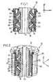
- Figure 1 is a sectional view of an exemplary embodiment of the antivibration device 10 according to the invention, this device comprising an inner armature 12 and an outer armature 36 cylindrical.
- the inner armature 12 and outer 36 are coaxial along a longitudinal axis Z.
- the inner armature 12 and outer 36 are made in a manner known per se, aluminum for example.
- a window frame 34 is interposed between the inner frame 12 and the outer frame 36.
- An elastomer body 14 is adhered to the internal frame 12 and to the window frame 34.
- the window frame 34 is cylindrical and centered on the axis Z. It has a length slightly greater than that of the outer frame 36 and a curved end 38. Thus, the outer frame 36 is fitted, narrowed and blocked on the window frame 34, with an elastomer layer 44 interposed therebetween. The bent end 38 blocks the downward movement of the window frame 34 on the outer frame 36, and provides sealing of the device.
- the window frame 34 has two metal flange elements 46, 48 corresponding to portions of a cylindrical surface substantially parallel to the outer frame 36 and having a recess 50.
- These two flange elements 46, 48 alone constitute the window frame 34. They are formed by stamping and then assembled by stapling, that is to say by interlocking and then by compression, along a direction parallel to the longitudinal axis Z.
- the window frame 34 may consist of a single stamped part and then curved so that two ends Longitudinals are brought together and held in place by stapling.
- the window frame may be composed of four flange elements, corresponding to portions of a cylindrical surface, assembled to each other by stapling in a direction parallel to the longitudinal axis Z.
- the first flange element 46 is symmetrical to the other with respect to the longitudinal axis Z.
- Each of the flange elements 46 or 48 comprises a recess 50 which in radial section has a "U" shape with three bearing surfaces. .
- Two of these bearing surfaces 52a, 52b correspond to the two branches of the "U” and are inclined at an acute angle with respect to the Z axis.
- the third 54 of these bearing surfaces, corresponding to the bottom of the "U” is substantially parallel to the Z axis.
- chambers 16, 18, 20, 22, 24, 26 are formed in the elastomeric body 14.
- the chambers 16, 18, 20, 22, 24, 26 are closed when the device 10 is assembled with the outer frame 36.
- the elastomer body 14 therefore comprises six openings corresponding to the chambers 16, 18, 20, 22, 24, 26. These openings are through and substantially straight in a direction parallel to the axis X. They open on a surface of the elastomer body 14 substantially cylindrical longitudinal axis Z.
- the chambers 16 and 18 or 20 and 22, of the first and third games, said axial clearances, are located substantially in the vicinity of the longitudinal ends of the device 10.
- a room 16 or 18 of the first game and a room 20 or 22 of the third set, located towards the same longitudinal end extend in a distal plane parallel to the median plane.
- the two distal planes are symmetrical with respect to the median plane.
- the chambers 16, 18, 20, 22 of the axial clearances have a section perpendicular to the substantially polygonal X axis with a side close to a bearing surface 52 and substantially parallel thereto (see FIGS. 1 and 2). . These chambers extend perpendicularly to their respective bearing surfaces 52, from this bearing surface 52 to the internal frame 12.
- the bearing surfaces 52 make it possible to transmit forces applied axially along the longitudinal axis Z, or even radially along the Y axis, and to increase the deformation of the section of the chambers and thus to increase the variations in the volume of the chambers. chambers 16 and 18 or 20 and 22 respectively of the first or third games.
- the chambers 24, 26 of the radial clearance have a section perpendicular to the substantially polygonal X axis with a side substantially parallel to the third bearing surface 54.
- the third bearing surface 54 makes it possible to transmit forces applied radially with respect to the longitudinal direction Z, between the internal and external armatures 36, to one of the chambers 24 or 26 of the second set.
- the two chambers 16 and 18 of the first game communicate with one another via a duct 28 extending essentially parallel to the longitudinal direction Z.
- the two chambers 20 and 22 of the third game communicate with each other via the conduit 30 extending substantially parallel to the Z direction.
- the ducts 28, 30 of the first and third sets of chambers and the duct 32 of the second set of chambers are located at diametrically opposed flange element level.
- the ducts 28, 30, 32 are formed in the elastomer layer 44.
- the ducts 28, 30, 32 then comprise an inner wall formed by a thin layer of elastomer adhered to a window frame 34, an outer wall formed of outer frame 36 and two edges formed in the thickness of the elastomer layer 44.
- ducts are completely sealed and allow the passage of liquid from one chamber to another.
- beads 56 surround each duct 28, 30, 32. These beads 56 protrude from the outer surface of the elastomer body 14 when the outer armature 36 is not placed on the window frame 34. When the device 10 is assembled, the beads 56 are crushed between the outer frames 36 and window 34, and provide sealing between the different chambers and ducts.
- the chambers 16, 18, 20, 22, 24, 26 and the conduits 28, 30, 38 are filled with a fluid, for example glycol.
- the fluid flows in each of these ducts 28, 30, 32 between the chambers 16 and 18, 20 and 22, 24 and 26, when the chambers are deformed. Movement of the fluid between the two chambers of each set is intended to contribute damping vibrations emanating from the various stresses to which the device 10 is subjected, in the longitudinal direction Z and in the radial direction Y.
- the present invention thus functions as follows:
- the inner armature 12 and the outer armature 30 are fixed on elements, undergoing vibrations. These vibrations are filtered on the one hand by the elastomer body 14 for high frequencies and damped on the other hand by the hydraulic chambers for low frequencies.
- the relative oscillations applied axially along the longitudinal axis or radially on one of the armatures 12, 36, result in reciprocating movements of the liquid from one chamber to another, and for a predetermined value of the frequency of the oscillations, the liquid contained in the duct 28, 30, 32 ensures efficient damping of the oscillations by resonance effect, at low frequencies.
- the passage of the fluid in the ducts 28, 30, 32 is effected at a maximum frequency and amplitude. These characteristics are determined by the dimensions of each duct 28, 30 or 32, such as the section and the length.
- the damping of the vibrations between the internal and external armatures 36 is maximal when the oscillations of the liquid are resonated.
- the deformation of the chambers is increased by the bearing surfaces 52, 54 of the window frame 34. These bearing surfaces act as a piston which exerts pressure on one of the chambers of a game.
- Radial damping is independent of the axial damping, which absorbs vibrations from both directions without interference, and thus independently determine the parameters of the conduits 28, 30, 32 to obtain a better result.
- This type of device 10 may in particular be applied for the suspension of the engine.
- the outer armature is then connected to the engine suspension arm, and the inner armature is connected to the body, to dampen the vibrations and they are not transmitted to the cabin.
- the invention also relates to a method of producing a device as described above.
- the elastomer body undergoes a heat treatment ensuring its hardening and the connection of the elastomeric body to the internal reinforcement is carried out according to a method known to those skilled in the art.
- the outer armature is fitted on the previously obtained piece, the latter being immersed in a liquid bath to fill the rooms.
- the latter may be filled by a vacuum filling method known to those skilled in the art.
- the outer armature is narrowed on the elastomer body.
- Each part of the mold comprises a number of fingers 74 defined according to the number of chambers to be produced.
- the semicylindrical shells 72 of the mold are brought together, so that the fingers 74 are placed facing each other and the ends of the fingers 74 are brought as close together as possible, even in contact.
- the fingerprint 74 then forms the chambers.
- the elastomer body is demolded in a direction parallel to the fingers 74, perpendicularly to the plane (Y, Z), which allows to have chambers which open on the cylindrical surface of the elastomeric body. This characteristic makes it possible to obtain a greater deformation of the opening of the chambers when they are stressed and consequently a greater thrust of the fluid from one chamber to another chamber of the same set.
- FIG. 6 shows a sectional view along two perpendicular planes of the antivibration device according to the second embodiment.
- FIG. 7 represents a perspective view of the integrated window frame in the device of FIG. 6.
- FIG. 8 shows another window frame that can be used in a device of the type shown in FIG.
- the device comprises an internal frame and an external frame, not shown, and a window frame 118 and an elastomer body 14. More specifically, the device comprises in the elastomer body 14 two sets of two chambers 78, 80, 82, 84, each chamber of the same set being interconnected by at least one duct.
- a first set 78, 80 is intended to damp the vibrations in the radial direction, and will be designated hereinafter by radial play.
- the other game called axial play, is intended to damp the vibrations in the axial direction, parallel to the longitudinal axis Z.
- the chambers 78, 80 of the radial clearance are disposed in a median plane perpendicular to the longitudinal axis Z.
- the radial clearance is substantially identical to that of the first embodiment. It comprises orthoradial chambers which open on the cylindrical surface of the elastomer body 14, and which have an opening of substantially circular shape.
- the axial clearance comprises two parallel through chambers 82, 84 and arranged towards the longitudinal ends of the device and which extend in two distal planes parallel to the median plane. These chambers are connected by two ducts of which only one 88 is shown in FIG. 6. Alternatively, they can be connected by a single duct.
- the chambers 82, 84 open out onto the cylindrical surface of the elastomer body 14 through a partially circular opening, that is to say having the shape of an arc of a circle, about the longitudinal axis Z of the elastomer body 14.
- L Opening then has a larger surface, because of its shape in a circular arc, the corresponding chamber is more easily deformable. This allows a greater damping of the vibrations, at the resonance frequency of the duct connecting the two chambers 82, 84.
- the armature window 118 is made by assembling two identical flange members 120a, 120b.
- Each flange element 120a, 120b is made by stamping and has a hollow cylindrical shape, directed longitudinally substantially parallel to the axis Z.
- the flange elements 120a, 120b are assembled at a first longitudinal end, so that the length of the flanges 120a, 120b the window frame is slightly larger than that of the outer frame.
- Each flange has a curved second longitudinal end, so that the outer reinforcement after assembly is locked on the window frame.
- the flange elements have cutouts 122 and narrow edges 124.
- the cutouts 122 delimit the sections of the chambers 78, 80 of the radial clearance.
- the constrictions 124 make it possible to obtain faces disposed facing one another, and by which the flange elements 120a, 120b are assembled by welding.
- the narrowed edges 124 have a U-shape, of which at least one of the branches 125 is directed parallel to the longitudinal axis Z so as to form bearing zones that can exert pressure on the deformable elastomer walls of the axial clearance chambers. and radial, in order to increase the amplitude of the fluid flow from one chamber to another.
- the elastomer walls of the chambers 78, 80, 82, 84 adjacent to the bearing zones may be made in a direction parallel to that of the surface of the bearing zones in order to improve the efficiency of the axial and radial damping.
- each flange member 120a, 120b has recesses, or windows, 126 partially circular, which are made in a median plane perpendicular to the longitudinal axis Z and correspond at the openings of the chambers 82, 84 of the axial play.
- Each chamber of the same set is connected by at least one conduit as described in the first embodiment.
- the chambers 82, 84 of axial play, arranged towards the longitudinal ends of the device, are connected by at least one duct 88, which extends longitudinally between the two chambers 82, 84.
- the chambers 82, 84 can communicate with each other via two adjacent conduits disposed separated by an elastomeric bead. These two conduits make it possible to ensure the passage of fluid from one chamber to another.
- the ducts connecting the chambers 78, 80, 82, 84 are delimited in part by the external reinforcement 36, by elastomer walls 14 formed during the molding of the device and by the flange members 120a, 120b optionally covered with a layer elastomer.
- the conduits are arranged parallel to the longitudinal axis Z or in a plane perpendicular to the longitudinal axis in order to damp the vibrations respectively in an axial or radial direction.
- the device according to the second embodiment operates in substantially the same manner as the device according to the first embodiment.
- the section of the chambers 82, 84 of the axial play being greater, the deformation of the section and the volume of the chambers 82, 84 is therefore also greater. Which increases the thrust force of the fluid from one first chamber to another, by compressing the fluid in a first chamber. At the resonant frequency of the duct, the damping is then greater than in the first embodiment.
- the device according to the second embodiment has in each chamber 82, 84 of the axial clearance, a transverse passage 112 delimited by the inner frame 12 and the window frame 118, and open on each of the chambers 82,84.
- This passage plays the role of an internal conduit through which the fluid passes.
- the device therefore has a damping capacity at a frequency, different from the resonance frequency of the ducts, already described, connecting the chambers 82, 84, which corresponds to the resonance frequency of the flow of the fluid in the passage 112.
- the device described in the preceding paragraph is implemented in the following manner.
- the flanges 120a, 120b of the window frame are made by stamping and then fixed by welding on the narrows 124. Then the inner frame 12 and the outer frame 36 are arranged in a mold before the injection of the elastomer.
- the mold comprises two semi-cylindrical shells 114 which comprise two fingers 116a, 116b as shown in FIG. 10 and in addition two fingers in the form of a half-ring 117a, 117b in order to form the chambers 82, 84 of axial play.
- the half-shells 114 are removed parallel to the transverse direction X. Draft angles are provided for easy removal. Subsequently, two internal membranes resulting from the elastomer elapsed between two fingers 116 facing each other during molding, are located in each chamber 82, 84 of the second set. These membranes can divide the chambers 82, 84 into two parts, but present then a Deformation capacity large enough to allow the flow of fluid in the ducts.
- the device comprises a single chamber 82, 84 through at each longitudinal end of the device. This thin membrane can also be pierced alone after a few physical tests of the device. The pierced membrane then forms the internal passages 112 mentioned above.
- two membranes may be created during the molding step and then drilled later.
- the window frame 92 of the device according to the second embodiment has a metal frame 94 formed of a hollow cylinder of central axis parallel to the longitudinal axis. Z.
- the metal frame has two recesses 96a, 96b on its cylindrical surface delimited by two longitudinal arms 98.
- Two plastic flange members 102a, 102b having the shape of a circular arc are attached to the arms 98. As shown, these flange members 102a, 102b are diametrically opposed, and form, when arranged on the longitudinal arms 98 of the window frame 92, a circle of diameter substantially smaller than the outer diameter of the circular ends 100a, 100b. Each element 102a, 102b have windows 104, which each constitute an opening of the chambers of the radial clearance through the window frame 92.
- the assembly of the flanges 102a, 102b of plastic forms with the metal frame 94 chamber openings 105a, 105b, corresponding to the chambers of axial play.
- the plastic flange members 102a, 102b may have one or more windows 104.
- the plastic flange members 102a, 102b further include bearing areas 106a, 106b, 106c, formed by protruding portions, directed inwardly of the window frame 92, and adjacent to the chambers 78, 80, 82, 84, so as to exert pressure on the chambers to change the fluid flow therein.
- the surfaces 106a, 106b of the bearing zones adjacent to the chambers 82, 84 of the axial play are perpendicular to the longitudinal axis Z
- the surfaces 106c of the bearing zones adjacent to the chambers 78, 80 of the radial clearance are perpendicular to the transverse axis Y.
- the plastics flange elements 102 are mounted on the metal frame 94 by snapping, which provides a modular window frame 92, and can easily change the flange members 102a, 102b.
- the window frame 92 obtained thus has the same windows as that described above, and is applied for anti-vibration devices as described in the second embodiment.
- the shapes of the sections of the chambers 82, 84 may vary depending on the shape of the fingerprints 116.
- the device comprises on the lower and upper parts of the body in elastomer a rigid washer (shown in dashed lines in Figure 6), fixed by interlocking on the inner frame.
- This washer is made of metal, and increases the pressure exerted on the chambers of the axial play, and therefore to increase their deformation, for a more effective damping.
- the window frame can be made entirely of rigid plastic, by molding. This makes it possible to obtain a diversity of shapes, and a lower manufacturing cost than with a metal frame.
Abstract
Description
La présente invention est relative aux dispositifs antivibratoires.The present invention relates to antivibration devices.
Plus particulièrement, l'invention concerne un dispositif antivibratoire hydraulique comprenant, une armature interne et une armature externe co-axiales selon un axe longitudinal Z, un corps en élastomère, disposé entre les armatures internes et externes et reliant ces dernières, ce corps en élastomère étant solidarisé à l'armature interne et coopérant avec l'armature externe pour former un ensemble étanche, le corps en élastomère comportant au moins deux jeux de deux chambres hydrauliques, les chambres d'un même jeu communiquant entre elles par l'intermédiaire d'un conduit, dans lequel circule un fluide, au moins un des jeux étant prévu pour l'amortissement de vibrations selon une direction choisie parmi une direction radiale et une direction axiale.More particularly, the invention relates to a hydraulic antivibration device comprising, an inner frame and a co-axial outer frame along a longitudinal axis Z, an elastomer body, disposed between the inner and outer frames and connecting them, this elastomeric body being secured to the internal frame and cooperating with the outer frame to form a sealed assembly, the elastomeric body having at least two sets of two hydraulic chambers, the rooms of the same game communicating with each other via a conduit, in which a fluid circulates, at least one of the games being provided for damping vibrations in a direction selected from a radial direction and an axial direction.
Le document FR-2 659 712-A1 décrit un exemple d'un manchon antivibratoire hydraulique de ce type, comportant deux armatures internes rigides. Des conduits sont formés par des gorges réalisées dans l'épaisseur d'une première armature interne. Une deuxième armature interne est emmanchée sur la première pour fermer l'ouverture longitudinale de chaque gorge.The document FR-2 659 712-A1 describes an example of a hydraulic antivibration sleeve of this type, comprising two rigid internal frames. Ducts are formed by grooves made in the thickness of a first internal frame. A second internal frame is fitted on the first to close the longitudinal opening of each groove.
La présente invention a notamment pour but de simplifier la fabrication de ce type de manchon.The present invention is intended in particular to simplify the manufacture of this type of sleeve.
A cet effet, selon l'invention, un dispositif du genre en question est caractérisé :
- en ce qu'il comporte une armature à fenêtre, disposée à l'intérieur du corps en élastomère et comportant au moins un élément de flasque à proximité de l'armature externe, et
- en ce que les conduits relient deux chambres d'un même jeu sur au moins une portion située entre un élément de flasque de l'armature à fenêtre et l'armature externe et comportent des parois formées par le corps en élastomère.
- in that it comprises a window frame arranged inside the elastomer body and having at least one flange element close to the outer armature, and
- in that the ducts connect two chambers of the same clearance on at least one portion situated between a flange element of the window frame and the outer frame and comprise walls formed by the elastomer body.
Grâce à ces dispositions, il n'est plus nécessaire de prévoir une armature interne pour y former les conduits. Dans le mode de réalisation du manchon selon l'invention tel que défini ci-dessus, les conduits sont réalisés au voisinage de l'armature externe qui obture des gorges formées dans le corps en élastomère. Au lieu d'usiner les gorges sur une pièce métallique constitutive d'une armature interne pour chaque manchon, celles-ci sont formées une fois pour toutes, sur le moule.Thanks to these provisions, it is no longer necessary to provide an internal armature to form the ducts. In the embodiment of the sleeve according to the invention as defined above, the ducts are made in the vicinity of the outer frame which closes grooves formed in the elastomeric body. Instead of machining the grooves on a metal part constituting an internal frame for each sleeve, they are formed once and for all on the mold.
Dans divers modes de réalisation du dispositif selon l'invention, on peut éventuellement avoir recours en outre à l'une et/ou à l'autre des dispositions suivantes :
- les chambres sont rectilignes et traversent le corps en élastomère selon une direction parallèle à un axe transversal X perpendiculaire à l'axe longitudinal Z ;
- l'armature à fenêtre présente des fenêtres délimitant une section des chambres
- le dispositif comporte :
- au moins un premier jeu de deux chambres, reliées entre elles par un premier conduit s'étendant essentiellement parallèlement à l'axe longitudinal Z, pour l'amortissement de vibrations selon la direction axiale,
- au moins un deuxième jeu de deux chambres, reliées entre elles par un deuxième conduit s'étendant essentiellement dans un plan perpendiculaire à l'axe longitudinal Z, pour l'amortissement de vibrations selon une direction radiale, et
- deux éléments de flasques distincts, les premier et deuxième conduits passant chacun entre un élément de flasque distinct et l'armature externe ;
- les premier et deuxième conduits sont diamétralement opposés l'un de l'autre ;
- des bourrelets en élastomère longent au moins une partie de chaque conduit, pour renforcer les propriétés d'étanchéité des conduits ;
- chaque chambre d'un premier jeu s'étend longitudinalement parallèlement à un plan médian et perpendiculaire à l'axe longitudinal Z, et est symétrique de l'autre chambre par rapport à ce plan médian et chaque chambre d'un deuxième jeu s'étend longitudinalement essentiellement dans le plan sensiblement médian, et est symétrique de l'autre par rapport à l'axe Z ;
- le dispositif comporte deux jeux de chambres prévus pour l'amortissement selon une direction axiale, ces deux jeux étant diamétralement opposés et disposés au voisinage des extrémités longitudinales du dispositif, le conduit reliant les deux chambres de chaque jeu s'étendant essentiellement selon l'axe longitudinal ;
- l'armature comporte au moins deux éléments de flasques semi-cylindriques métalliques et assemblés par agrafage ;
- l'armature à fenêtre comporte une ossature métallique sur laquelle sont rapportés des éléments de flasque en matière plastique ;
- l'armature à fenêtre comporte deux éléments de flasques métalliques cylindriques assemblés par soudage ;
- l'armature à fenêtre présente au moins une zone d'appui en forme de U, dont les branches sont adjacentes à des chambres ;
- la zone d'appui est formée par une partie en saillie et dirigée vers l'intérieur des éléments de flasque en matière plastique ;
- l'armature est constituée entièrement en matière plastique.
- the chambers are rectilinear and pass through the elastomeric body in a direction parallel to a transverse axis X perpendicular to the longitudinal axis Z;
- the window frame has windows defining a section of the rooms
- the device comprises:
- at least a first set of two chambers, interconnected by a first duct extending substantially parallel to the longitudinal axis Z, for damping vibrations in the axial direction,
- at least a second set of two chambers interconnected by a second duct extending substantially in a plane perpendicular to the longitudinal axis Z for vibration damping according to a radial direction, and
- two separate flange members, the first and second conduits each passing between a separate flange member and the outer frame;
- the first and second conduits are diametrically opposed to each other;
- elastomeric beads along at least a portion of each conduit, to enhance the sealing properties of the conduits;
- each chamber of a first game extends longitudinally parallel to a median plane and perpendicular to the longitudinal axis Z, and is symmetrical with the other chamber with respect to this median plane and each chamber of a second set extends longitudinally substantially in the substantially median plane, and is symmetrical to the other with respect to the Z axis;
- the device comprises two sets of chambers provided for damping in an axial direction, these two sets being diametrically opposed and arranged in the vicinity of the longitudinal ends of the device, the duct connecting the two chambers of each set extending essentially along the axis longitudinal;
- the armature comprises at least two elements of metal semi-cylindrical flanges and assembled by stapling;
- the window frame comprises a metal frame to which plastic flange elements are attached;
- the window frame comprises two cylindrical metal flange elements assembled by welding;
- the window frame has at least one U-shaped bearing zone, the branches of which are adjacent to chambers;
- the bearing area is formed by a projecting and inwardly directed portion of the plastic flange members;
- the frame is made entirely of plastic.
Par ailleurs, l'invention a également pour objet un procédé de fabrication du dispositif défini ci-dessus caractérisé par le fait que l'on place une armature à fenêtre dans un moule, avec l'armature interne, et que le moule est formé d'au moins deux parties, l'une au moins de ces parties comportant au moins un doigt et le moule étant adapté pour former, lorsqu'il est fermé, au moins deux empreintes de chambre et au moins un conduit reliant deux chambres, ce conduit ayant au moins une portion destinée à être située entre l'armature à fenêtre et l'armature externe.Furthermore, the subject of the invention is also a method of manufacturing the device defined above characterized by the fact that a window frame is placed in a mold, with the internal frame, and that the mold is formed of at least two parts, at least one of these parts comprising at least one finger and the mold being adapted to form, when closed, at least two chamber impressions and at least one duct connecting two chambers, this duct having at least one portion to be located between the window frame and the outer frame.
Ce procédé comporte une opération de démoulage au cours de laquelle les deux parties du moule sont écartées selon une direction perpendiculaire à la direction axiale.This method comprises a demolding operation during which the two parts of the mold are spaced in a direction perpendicular to the axial direction.
D'autres caractéristiques et avantages de l'invention apparaîtront au cours de la description suivante de deux de ses modes de réalisation, donné à titre d'exemples non limitatifs, en regard des dessins joints.Other features and advantages of the invention will become apparent from the following description of two of its embodiments, given by way of non-limiting examples, with reference to the accompanying drawings.
Sur les dessins :
- la figure 1 représente une vue en coupe longitudinale d'un premier mode de réalisation du dispositif selon l'invention ;
- la figure 2 est une vue en perspective, avec coupe selon deux plans perpendiculaires, du dispositif représenté sur la figure 1 ;
- la figure 3 représente une vue en élévation latérale du dispositif des figures 1 et 2, sans l'armature externe ;
- la figure 4 représente une vue analogue à celle de la figure 3 dans laquelle le dispositif a subi une rotation de 180 degrés autour de l'axe longitudinal Z ;
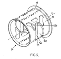
- la figure 5 représente une vue en perspective de l'armature à fenêtre du dispositif représenté aux figures 1 à 4 ;
- la figure 6 représente une vue similaire à celle de la figure 2 d'un dispositif selon un second mode de réalisation ;
- la figure 7 représente une vue en perspective de l'armature à fenêtre selon le second mode de réalisation du dispositif ;
- la figure 8 représente une vue en perspective d'une variante de réalisation de l'armature à fenêtre du dispositif selon le second mode de réalisation ;
- la figure 9 représente une vue de la face interne d'une coquille du moule du dispositif selon le premier mode de réalisation ;
- la figure 10 représente une vue de la face interne d'une coquille du moule du dispositif selon le second mode de réalisation.
- Figure 1 shows a longitudinal sectional view of a first embodiment of the device according to the invention;
- FIG. 2 is a perspective view, with section in two perpendicular planes, the device shown in Figure 1;
- Figure 3 shows a side elevational view of the device of Figures 1 and 2, without the outer armature;
- FIG. 4 represents a view similar to that of FIG. 3 in which the device has been rotated 180 degrees about the longitudinal axis Z;
- Figure 5 shows a perspective view of the window frame of the device shown in Figures 1 to 4;
- FIG. 6 represents a view similar to that of FIG. 2 of a device according to a second embodiment;
- Figure 7 shows a perspective view of the window frame according to the second embodiment of the device;
- FIG. 8 represents a perspective view of an alternative embodiment of the window frame of the device according to the second embodiment;
- Figure 9 shows a view of the inner face of a mold shell of the device according to the first embodiment;
- Figure 10 shows a view of the inner face of a mold shell of the device according to the second embodiment.
Sur les différentes figures, les mêmes références désignent des éléments identiques ou similaires.In the different figures, the same references designate identical or similar elements.
Un exemple d'un premier mode de réalisation est décrit ci-dessous en relation avec les figures 1 à 5.An example of a first embodiment is described below in relation to FIGS. 1 to 5.
Dans la description qui va suivre, on adoptera deux orientations transversales et une orientation longitudinale, selon les orientations indiquées respectivement par le trièdre X, Y, Z direct.In the following description, two transverse orientations and one longitudinal orientation will be adopted, according to the orientations indicated respectively by the direct X, Y, Z trihedron.
La figure 1 est une vue en coupe d'un exemple de mode de réalisation du dispositif antivibratoire 10 selon l'invention, ce dispositif comprenant une armature interne 12 et une armature externe 36 cylindriques. Les armatures interne 12 et externe 36 sont coaxiales selon un axe longitudinal Z. Les armatures interne 12 et externe 36 sont réalisées d'une manière connue en soi, en aluminium par exemple.Figure 1 is a sectional view of an exemplary embodiment of the
Une armature à fenêtre 34 est intercalée entre l'armature interne 12 et l'armature externe 36.A
Un corps en élastomère 14 est adhérisé sur l'armature interne 12 et sur l'armature à fenêtre 34.An
L'armature à fenêtre 34 est cylindrique et centrée sur l'axe Z. Elle possède une longueur légèrement supérieure à celle de l'armature externe 36 et une extrémité recourbée 38. Ainsi, l'armature externe 36 est emmanchée, rétreinte et bloquée sur l'armature à fenêtre 34, avec une couche d'élastomère 44 intercalée entre les deux. L'extrémité recourbée 38 bloque le déplacement vers le bas de l'armature à fenêtre 34 sur l'armature externe 36, et permet d'obtenir l'étanchéité du dispositif.The
Comme représenté sur la figure 5, l'armature à fenêtre 34 présente deux éléments de flasque métalliques 46, 48 correspondant à des portions d'une surface cylindrique sensiblement parallèle à l'armature externe 36 et comportant un renfoncement 50.As shown in FIG. 5, the
Ces deux éléments de flasques 46, 48 constituent à eux seuls l'armature à fenêtre 34. Ils sont formés par emboutissage puis assemblés par agrafage, c'est à dire par emboîtement puis par compression, le long d'une direction parallèle à l'axe longitudinal Z.These two
Selon une variante de réalisation de l'armature à fenêtre 34, celle-ci peut être constituée d'une seule pièce emboutie, puis recourbée pour que deux extrémités longitudinales soient rapprochées et maintenues par agrafage.According to an alternative embodiment of the
Selon une autre variante, l'armature à fenêtre peut être composée de quatre éléments de flasques, correspondant à des portions d'une surface cylindrique, assemblés les uns aux autres par agrafage selon une direction parallèle à l'axe longitudinal Z.According to another variant, the window frame may be composed of four flange elements, corresponding to portions of a cylindrical surface, assembled to each other by stapling in a direction parallel to the longitudinal axis Z.
Le premier élément de flasque 46 est symétrique de l'autre par rapport à l'axe longitudinal Z. Chacun des éléments de flasque 46 ou 48 comporte un renfoncement 50 qui présente en coupe radiale une forme en "U" avec trois surfaces d'appui. Deux de ces surfaces d'appui 52a, 52b correspondent aux deux branches du "U" et sont inclinées selon un angle aigu par rapport à l'axe Z. La troisième 54 de ces surfaces d'appui, correspondant au fond du "U", est sensiblement parallèle à l'axe Z.The
Comme représenté sur la figure 3, des chambres 16, 18, 20, 22, 24, 26 sont formées dans le corps en élastomère 14. Les chambres 16, 18, 20, 22, 24, 26 sont fermées lorsque le dispositif 10 est assemblé avec l'armature externe 36.As shown in FIG. 3,
Le corps en élastomère 14 comporte donc six ouvertures correspondant aux chambres 16, 18, 20, 22, 24, 26. Ces ouvertures sont traversantes et sensiblement rectilignes selon une direction parallèle à l'axe X. Elles débouchent sur une surface du corps en élastomère 14 sensiblement cylindrique d'axe longitudinal Z.The
Les chambres 16 et 18 ou 20 et 22, des premier et troisième jeux dits jeux axiaux, sont situées sensiblement au voisinage des extrémités longitudinales du dispositif 10. Un deuxième jeu de chambres 24, 26, dit jeu radial, est placé dans le plan médian au dispositif 10 et perpendiculaire à l'axe longitudinal Z.The
Une chambre 16 ou 18 du premier jeu et une chambre 20 ou 22 du troisième jeu, situées vers la même extrémité longitudinale s'étendent dans un plan distal parallèle au plan médian. Les deux plans distaux sont symétriques par rapport au plan médian.A
Les chambres 16, 18, 20, 22 des jeux axiaux présentent une section perpendiculaire à l'axe X sensiblement polygonale avec un côté à proximité d'une surface d'appui 52 et sensiblement parallèle à celle-ci (voir figures 1 et 2). Ces chambres s'étendent perpendiculairement à leurs surfaces d'appui 52 respectives, de cette surface d'appui 52 à l'armature interne 12.The
Les surfaces d'appui 52 permettent de transmettre des efforts appliqués axialement selon l'axe longitudinal Z, ou même radialement selon l'axe Y, et d'augmenter la déformation de la section des chambres et donc d'augmenter les variations du volume des chambres 16 et 18 ou 20 et 22 respectivement des premier ou troisième jeux.The bearing surfaces 52 make it possible to transmit forces applied axially along the longitudinal axis Z, or even radially along the Y axis, and to increase the deformation of the section of the chambers and thus to increase the variations in the volume of the chambers.
Les chambres 24, 26 du jeu radial présentent une section perpendiculaire à l'axe X sensiblement polygonale avec un côté sensiblement parallèle à la troisième surface d'appui 54.The
La troisième surface d'appui 54 permet de transmettre des efforts appliqués radialement par rapport à la direction longitudinale Z, entre les armatures interne 12 et externe 36, à l'une des chambres 24 ou 26 du deuxième jeu.The
Comme représenté sur la figure 3, les deux chambres 16 et 18 du premier jeu communiquent entre elles par l'intermédiaire d'un conduit 28 s'étendant essentiellement parallèlement à la direction longitudinale Z.As shown in FIG. 3, the two
Les deux chambres 20 et 22 du troisième jeu communiquent entre elles par l'intermédiaire du conduit 30 s'étendant essentiellement parallèlement à la direction Z.The two
Comme représenté sur la figure 4, les deux chambres 24 et 26 du deuxième jeu communiquent entre elles par l'intermédiaire d'un conduit 32 s'étendant essentiellement de manière circulaire dans un plan médian perpendiculaire à l'axe longitudinal Z.As shown in FIG. 4, the two
Les conduits 28, 30 des premier et troisième jeux de chambres et le conduit 32 du deuxième jeu de chambres sont situés au niveau d'élément de flasques opposés diamétralement.The
Les conduits 28, 30, 32 sont formés dans la couche d'élastomère 44. Les conduits 28, 30, 32 comportent alors une paroi intérieure formée par une fine couche d'élastomère adhérisée sur armature à fenêtre 34, une paroi extérieure formée de l'armature externe 36 et deux bords formés dans l'épaisseur de la couche d'élastomère 44.The
Ces conduits sont totalement étanches et permettent le passage du liquide d'une chambre vers l'autre. Pour renforcer leur étanchéité, des bourrelets 56 entourent chaque conduit 28, 30, 32. Ces bourrelets 56 font saillie sur la surface externe du corps en élastomère 14 lorsque l'armature externe 36 n'est pas placée sur l'armature à fenêtre 34. Lorsque le dispositif 10 est assemblé, les bourrelets 56 sont écrasés entre les armatures externe 36 et à fenêtre 34, et assurent l'étanchéité entre les différentes chambres et conduits.These ducts are completely sealed and allow the passage of liquid from one chamber to another. To enhance their sealing,
Lorsque le dispositif 10 est assemblé, les chambres 16, 18, 20, 22, 24, 26 et les conduits 28, 30, 38 sont remplis d'un fluide, par exemple du glycol. Le fluide circule dans chacun de ces conduits 28, 30, 32 entre les chambres 16 et 18, 20 et 22, 24 et 26, lorsque les chambres sont déformées. Le déplacement du fluide entre les deux chambres de chaque jeu est prévu pour contribuer à amortir des vibrations émanant des différentes sollicitations auxquelles le dispositif 10 est soumis, selon la direction longitudinale Z et selon la direction radiale Y.When the
La présente invention fonctionne donc de la manière suivante :The present invention thus functions as follows:
L'armature interne 12 et l'armature externe 30 sont fixées sur des éléments, subissant des vibrations. Ces vibrations sont filtrées d'une part par le corps en élastomère 14 pour les hautes fréquences et amorties d'autre part par les chambres hydrauliques, pour les basses fréquences. Les oscillations relatives appliquées axialement selon l'axe longitudinal ou radialement sur l'une des armatures 12, 36, se traduisent par des mouvements alternatifs du liquide d'une chambre à l'autre, et pour une valeur prédéterminée de la fréquence des oscillations, le liquide contenu dans le conduit 28, 30, 32 assure un amortissement efficace des oscillations par effet de résonance, à basses fréquences.The
En effet, le passage du fluide dans les conduits 28, 30, 32, s'effectue selon une fréquence et une amplitude maximum. Ces caractéristiques sont déterminées par les dimensions de chaque conduit 28, 30 ou 32, telles que la section et la longueur. L'amortissement des vibrations entre les armatures interne 12 et externe 36 est maximal lorsque les oscillations du liquide sont mises en résonance. De plus, la déformation des chambres est augmentée par les surfaces d'appui 52, 54 de l'armature à fenêtre 34. Ces surfaces d'appui exercent le rôle d'un piston qui exerce une pression sur l'une des chambres d'un jeu.Indeed, the passage of the fluid in the
L'amortissement radial est indépendant de l'amortissement axial, ce qui permet d'absorber les vibrations provenant des deux directions, sans interférences, et ainsi de déterminer indépendamment les paramètres des conduits 28, 30, 32 pour obtenir un meilleur résultat.Radial damping is independent of the axial damping, which absorbs vibrations from both directions without interference, and thus independently determine the parameters of the
Grâce au dispositif selon le mode de réalisation de l'invention décrit ci-dessus, on peut obtenir des courses axiales importantes, par exemple de 6 mm.With the device according to the embodiment of the invention described above, one can obtain significant axial strokes, for example 6 mm.
Ce type de dispositif 10 peut notamment être appliqué pour la suspension du moteur. L'armature externe est alors reliée au bras de suspension du moteur, et l'armature interne est reliée à la caisse, pour amortir les vibrations et qu'elles ne soient pas transmises à l'habitacle.This type of
L'invention concerne aussi un procédé de réalisation d'un dispositif tel que décrit ci-dessus.The invention also relates to a method of producing a device as described above.
Dans un exemple de mode de mise en oeuvre du procédé selon l'invention :
- on positionne l'armature interne, recouverte d'un adhésif, et l'armature à fenêtre, dans un moule en deux parties, formée chacune par exemple par une coquille semi-cylindrique 72 représentée à la figure 9.
- on injecte le corps en élastomère dans le moule ;
- les deux parties du moule sont écartées après durcissement de l'élastomère.
- the internal reinforcement, covered with an adhesive, and the window frame are positioned in a two-part mold, each formed for example by a
semi-cylindrical shell 72 shown in FIG. 9. - the elastomer body is injected into the mold;
- the two parts of the mold are separated after curing of the elastomer.
Le corps en élastomère subit un traitement thermique assurant son durcissement et la liaison du corps élastomère sur l'armature interne est réalisé selon un procédé connu de l'Homme du Métier.The elastomer body undergoes a heat treatment ensuring its hardening and the connection of the elastomeric body to the internal reinforcement is carried out according to a method known to those skilled in the art.
Puis l'armature externe est emmanchée sur la pièce précédemment obtenue, celle-ci étant plongée dans un bain de liquide afin de remplir les chambres. De manière alternative, ces dernières peuvent être remplies par un procédé de remplissage sous vide connu de l'homme du métier. Enfin l'armature externe est rétreinte sur le corps en élastomère.Then the outer armature is fitted on the previously obtained piece, the latter being immersed in a liquid bath to fill the rooms. Alternatively, the latter may be filled by a vacuum filling method known to those skilled in the art. Finally the outer armature is narrowed on the elastomer body.
Chaque partie du moule comporte un nombre de doigts 74 défini en fonction du nombre de chambre à réaliser. Pour former le moule, avant injection de l'élastomère, les coquilles semi-cylindriques 72 du moule sont rapprochées, de manière à ce que les doigts 74 soient placés en vis-à-vis et les extrémités des doigts 74 soient rapprochées au maximum, voire en contact. L'empreinte des doigts 74 forme alors les chambres.Each part of the mold comprises a number of
Selon un mode de réalisation particulier, le corps en élastomère est démoulé selon une direction parallèle aux doigts 74, perpendiculairement au plan (Y, Z), ce qui permet d'avoir des chambres qui débouchent sur la surface cylindrique du corps en élastomère. Cette caractéristique permet d'obtenir une déformation plus grande de l'ouverture des chambres lorsqu'elles sont sollicitées et par conséquent une poussée du fluide plus importante d'une chambre vers une autre chambre d'un même jeu.According to a particular embodiment, the elastomer body is demolded in a direction parallel to the
L'invention n'est nullement limitée aux modes d'application et de réalisation décrits ci-dessus. D'autres modes de réalisation permettent d'obtenir des résultats similaires.The invention is not limited to the modes of application and embodiments described above. Other embodiments provide similar results.
Un second mode de réalisation du dispositif est représenté aux figures 6 à 8. La figure 6 représente une vue en coupe selon deux plans perpendiculaires du dispositif antivibratoire selon le deuxième mode de réalisation. La figure 7 représente une vue en perspective de l'armature à fenêtre intégrée dans le dispositif de la figure 6. La figure 8 représente une autre armature à fenêtre pouvant être utilisée dans un dispositif du type représenté à la figure 6.A second embodiment of the device is shown in Figures 6 to 8. Figure 6 shows a sectional view along two perpendicular planes of the antivibration device according to the second embodiment. FIG. 7 represents a perspective view of the integrated window frame in the device of FIG. 6. FIG. 8 shows another window frame that can be used in a device of the type shown in FIG.
Le dispositif, représenté partiellement à la figure 6 comporte une armature interne et une armature externe, non représentées, et une armature à fenêtre 118 et un corps en élastomère 14. Plus précisément le dispositif comporte dans le corps en élastomère 14 deux jeux de deux chambres 78, 80, 82, 84, chaque chambre d'un même jeu étant reliée entre elles par au moins un conduit. Un premier jeu 78, 80 est destiné à amortir les vibrations selon la direction radiale, et sera désigné ci-après par jeu radial. L'autre jeu, dit jeu axial, est destiné à amortir les vibrations selon la direction axiale, parallèle à l'axe longitudinal Z.The device, partially shown in FIG. 6, comprises an internal frame and an external frame, not shown, and a
Les chambres 78, 80 du jeu radial sont disposées dans un plan médian perpendiculaire à l'axe longitudinal Z. Le jeu radial est sensiblement identique à celui du premier mode de réalisation. Il comporte dés chambres orthoradiales qui débouchent sur la surface cylindrique du corps en élastomère 14, et qui présentent une ouverture de forme sensiblement circulaire.The
Le jeu axial comporte deux chambres 82, 84 traversantes parallèles et disposées vers les extrémités longitudinales du dispositif et qui s'étendent dans deux plans distaux parallèles au plan médian. Ces chambres sont reliées par deux conduits dont un seul 88 est représenté sur la figure 6. Alternativement, elles peuvent être reliées par un seul conduit.The axial clearance comprises two parallel through
Les chambres 82, 84 débouchent sur la surface cylindrique du corps en élastomère 14 par une ouverture partiellement circulaire, c'est à dire ayant la forme d'un arc de cercle, autour de l'axe longitudinal Z du corps en élastomère 14. L'ouverture présente alors une surface plus importante, du fait de sa forme en arc de cercle, la chambre correspondant est donc plus facilement déformable. Cela permet un amortissement plus important des vibrations, à la fréquence de résonance du conduit reliant les deux chambres 82, 84.The
Comme représenté à la figure 7, l'armature à fenêtre 118 est réalisée par assemblage de deux éléments de flasques 120a, 120b identiques. Chaque éléments de flasque 120a, 120b est réalisé par emboutissage et présente une forme cylindrique creuse, dirigée longitudinalement sensiblement parallèlement à l'axe Z. Les éléments de flasques 120a, 120b sont assemblés au niveau une première extrémité longitudinale, de manière que la longueur de l'armature à fenêtre soit légèrement supérieure à celle de l'armature externe. Chaque flasque présente une deuxième extrémité longitudinale recourbée, de manière à ce que l'armature externe après assemblage soit bloquée sur l'armature à fenêtre. De plus les éléments de flasques présentent des découpes 122 et des bords rétreints 124.As shown in FIG. 7, the
Les découpes 122 délimitent les sections des chambres 78, 80 du jeu radial. Les rétreints 124 permettent d'obtenir des faces disposées en regard l'une de l'autre, et par lesquelles les éléments de flasques 120a, 120b sont assemblés par soudage. De plus les bords rétreints 124 présentent une forme en U, dont au moins une des branches 125 est dirigée parallèlement à l'axe longitudinal Z pour former des zones d'appui pouvant exercer une pression sur les parois déformables en élastomère des chambres du jeu axial et radial, afin d'augmenter l'amplitude du flux du fluide d'une chambre à l'autre. Les parois en élastomère des chambres 78, 80, 82, 84 adjacentes aux zones d'appui peuvent être réalisées selon une direction parallèle à celle de la surface des zones d'appui pour gagner en efficacité sur l'amortissement axial et radial.The
De plus chaque éléments de flasque 120a, 120b comporte des évidements, ou fenêtres, 126 partiellement circulaires, qui sont réalisés dans un plan médian perpendiculaire à l'axe longitudinal Z et correspondent aux ouvertures des chambres 82, 84 du jeu axial.In addition each
Chaque chambre d'un même jeu est relié par au moins un conduit tel que décrit dans le premier mode de réalisation. Les chambres 82, 84 du jeu axial, disposées vers les extrémités longitudinales du dispositif, sont reliées par au moins un conduit 88, qui s'étend longitudinalement entre les deux chambres 82, 84. Selon une variante de l'invention les chambres 82, 84 peuvent communiquer entre elles par l'intermédiaire de deux conduits disposées adjacents et séparés par un bourrelet en élastomère. Ces deux conduits permettent d'assurer le passage du fluide d'une chambre à l'autre.Each chamber of the same set is connected by at least one conduit as described in the first embodiment. The
Les conduits reliant les chambres 78, 80, 82, 84 sont délimités en partie par l'armature externe 36, par des parois en élastomère 14 formées lors du moulage du dispositif et par les éléments de flasque 120a, 120b éventuellement recouverts d'une couche d'élastomère. Les conduits sont disposés parallèlement à l'axe longitudinal Z ou dans un plan perpendiculaire à l'axe longitudinal afin d'amortir les vibrations respectivement selon une direction axiale ou radiale.The ducts connecting the
Le dispositif selon le second mode de réalisation fonctionne sensiblement de la même manière que le dispositif selon le premier mode de réalisation.The device according to the second embodiment operates in substantially the same manner as the device according to the first embodiment.
Lorsque les armatures internes 12 et externes 36 sont soumises à des sollicitations, les chambres 78, 80, 82, 84 des premier et deuxième jeux se déforment, ce qui entraîne le déplacement du fluide d'une chambre à l'autre, par l'intermédiaire des conduits 88.When the
Dans le deuxième mode de réalisation, la section des chambres 82, 84 du jeu axial étant plus importante, la déformation de la section et du volume des chambres 82, 84 est donc aussi plus importante. Ce qui augmente la force de poussée du fluide d'une première chambre à l'autre, par compression du fluide dans une première chambre. A la fréquence de résonance du conduit, l'amortissement est alors plus important que dans le premier mode de réalisation.In the second embodiment, the section of the
De plus le dispositif selon le second mode de réalisation présente dans chaque chambre 82, 84 du jeu axial, un passage 112 transversal délimité par l'armature interne 12 et l'armature à fenêtres 118, et ouvert sur chacune des chambres 82,84. Ce passage joue le rôle d'un conduit interne à travers lequel passe le fluide. Le dispositif présente donc une capacité d'amortissement à une fréquence, différente de la fréquence de résonance des conduits, déjà décrits, reliant les chambres 82, 84, qui correspond à la fréquence de résonance de l'écoulement du fluide dans le passage 112.Furthermore the device according to the second embodiment has in each
Le dispositif décrit dans le paragraphe précédent est réalisé de la manière suivante. Les flasques 120a, 120b de l'armature à fenêtre sont réalisés par emboutissage puis fixés par soudage sur les rétreints 124. Puis l'armature interne 12 et l'armature externe 36 sont disposées dans un moule avant l'injection de l'élastomère.The device described in the preceding paragraph is implemented in the following manner. The
Le moule comporte deux coquilles semi-cylindriques 114 qui comprennent deux doigts 116a, 116b tels que représentés à la figure 10 et en outre deux doigts en forme de demi-anneau 117a, 117b afin de former les chambres 82, 84 du jeu axial.The mold comprises two
Après injection de l'élastomère, les demi-coquilles 114 sont retirées parallèlement à la direction transversale X. Des angles de dépouille sont prévus pour un retrait facile. Par la suite, deux membranes internes résultant de l'élastomère écoulé entre deux doigts 116 en regard lors du moulage, sont situées dans chaque chambre 82, 84 du deuxième jeu. Ces membranes peuvent diviser les chambres 82, 84 en deux parties, mais présentent alors une capacité de déformation suffisamment importante pour permettre l'écoulement du fluide dans les conduits. Lorsque les membranes sont percées, le dispositif comporte une seule chambre 82, 84 traversante à chaque extrémité longitudinale du dispositif. Cette membrane de faible épaisseur peut aussi se percer seule après quelques tests physiques du dispositif. La membrane percée forme alors les passages 112 internes cités ci-dessus. De même, entre les deux doigts 116a, 116b du moule du dispositif selon le premier mode de réalisation, deux membranes peuvent être crées pendant l'étape de moulage puis percées ultérieurement.After injection of the elastomer, the half-
Selon une variante du deuxième mode de réalisation, représentée à la figure 8, l'armature à fenêtre 92 du dispositif selon le second mode de réalisation présente une ossature métallique 94 formée d'un cylindre creux d'axe central parallèle à l'axe longitudinal Z. L'ossature métallique présente deux évidements 96a, 96b sur sa surface cylindrique, délimités par deux bras longitudinaux 98.According to a variant of the second embodiment, represented in FIG. 8, the
Deux éléments de flasques en matière plastique 102a, 102b présentant la forme d'un arc de cercle sont rapportés sur les bras 98. Tel que représentés, ces éléments de flasque 102a, 102b sont diamétralement opposés, et forment, lorsqu'ils sont disposés sur les bras longitudinaux 98 de l'armature à fenêtre 92, un cercle de diamètre sensiblement inférieur au diamètre externe des extrémités circulaires 100a, 100b. Chaque élément 102a, 102b présentent des fenêtres 104, qui constituent chacune une ouverture des chambres du jeu radial à travers l'armature à fenêtre 92.Two
L'assemblage des flasques 102a, 102b en matière plastique forme avec l'ossature métallique 94 des ouvertures de chambre 105a, 105b, correspondant aux chambres du jeu axial.The assembly of the
A partir de ce qui est décrit ci-dessus, il est possible de choisir les formes des éléments de flasques 102a, 102b en matière plastique et de les positionner en fonction des formes voulues, plus ou moins complexes, de l'armature à fenêtre 92. En effet, les éléments de flasques 102a, 102b en matière plastique peuvent présenter une ou plusieurs fenêtre 104.From what is described above, it is possible to choose the shapes of the
Les éléments de flasques en matière plastique 102a, 102b comportent en outre des zones d'appui 106a, 106b, 106c, formées par des parties en saillie, dirigées vers l'intérieur de l'armature à fenêtre 92, et adjacentes aux chambres 78, 80, 82, 84, de manière à exercer une pression sur les chambres pour modifier l'écoulement du fluide dans celles-ci. Les surfaces 106a, 106b des zones d'appui adjacentes aux chambres 82, 84 du jeu axial sont perpendiculaires à l'axe longitudinal Z, et les surfaces 106c des zones d'appui adjacentes aux chambres 78, 80 du jeu radial sont perpendiculaires à l'axe transversal Y.The
Les éléments de flasques en matière plastique 102 sont montés sur l'ossature métallique 94 par encliquetage, ce qui permet d'obtenir une armature à fenêtre 92 modulable, et de pouvoir changer aisément les éléments de flasque 102a, 102b.The plastics flange elements 102 are mounted on the
L'armature à fenêtre 92 obtenue présente donc les mêmes fenêtres que celle décrite précédemment, et est appliquée pour des dispositifs anti-vibratoire tels que décrits dans le second mode de réalisation.The
Il est à noter que lors du moulage les formes des sections des chambres 82, 84 peuvent varier en fonction de la forme des empreintes des doigts 116.It should be noted that during molding the shapes of the sections of the
Dans une variante de réalisation pouvant s'appliquer aux deux modes de réalisation, le dispositif comporte sur les parties inférieure et supérieure du corps en élastomère une rondelle rigide (représentée en pointillé sur la figure 6), fixée par emboîtement sur l'armature interne. Cette rondelle est réalisée en métal, et permet d'augmenter la pression exercée sur les chambres du jeu axial, et donc d'augmenter leur déformation, pour un amortissement plus efficace.In an alternative embodiment that can be applied to both embodiments, the device comprises on the lower and upper parts of the body in elastomer a rigid washer (shown in dashed lines in Figure 6), fixed by interlocking on the inner frame. This washer is made of metal, and increases the pressure exerted on the chambers of the axial play, and therefore to increase their deformation, for a more effective damping.
Selon une autre variante de l'invention, l'armature à fenêtre peut être réalisée entièrement en matière plastique rigide, par moulage. Ce qui permet d'obtenir une diversité de formes, et un coût de fabrication moins élevé qu'avec une armature métallique.According to another variant of the invention, the window frame can be made entirely of rigid plastic, by molding. This makes it possible to obtain a diversity of shapes, and a lower manufacturing cost than with a metal frame.
Claims (16)
Applications Claiming Priority (1)
| Application Number | Priority Date | Filing Date | Title |
|---|---|---|---|
| FR0410705A FR2876429B1 (en) | 2004-10-11 | 2004-10-11 | HYDRAULIC ANTI-VIBRATION DEVICE FOR A VEHICLE AND METHOD OF MANUFACTURING SUCH A DEVICE |
Publications (2)
| Publication Number | Publication Date |
|---|---|
| EP1645773A1 true EP1645773A1 (en) | 2006-04-12 |
| EP1645773B1 EP1645773B1 (en) | 2011-01-12 |
Family
ID=34951150
Family Applications (1)
| Application Number | Title | Priority Date | Filing Date |
|---|---|---|---|
| EP05292104A Expired - Fee Related EP1645773B1 (en) | 2004-10-11 | 2005-10-10 | Hydraulic antivibration device for vehicles and process for manufacturing such a device |
Country Status (6)
| Country | Link |
|---|---|
| US (1) | US20060081427A1 (en) |
| EP (1) | EP1645773B1 (en) |
| BR (1) | BRPI0505772A (en) |
| DE (1) | DE602005025839D1 (en) |
| ES (1) | ES2359895T3 (en) |
| FR (1) | FR2876429B1 (en) |
Cited By (2)
| Publication number | Priority date | Publication date | Assignee | Title |
|---|---|---|---|---|
| CN103231641A (en) * | 2013-05-03 | 2013-08-07 | 无锡市中捷减震器有限公司 | Local support part of automobile engine |
| CN110159702A (en) * | 2019-06-21 | 2019-08-23 | 浙江向隆机械有限公司 | A kind of external bifrequency semiaxis dynamic vibration absorber |
Families Citing this family (6)
| Publication number | Priority date | Publication date | Assignee | Title |
|---|---|---|---|---|
| GB2453783A (en) * | 2007-10-19 | 2009-04-22 | Ford Global Tech Llc | Bushing |
| DE102012213447A1 (en) | 2012-07-31 | 2014-02-06 | Zf Friedrichshafen Ag | Hydraulically damping bush bearing |
| DE102012213446A1 (en) * | 2012-07-31 | 2014-02-06 | Zf Friedrichshafen Ag | Hydraulically damping bush bearing |
| CN103216567A (en) * | 2013-05-03 | 2013-07-24 | 无锡市中捷减震器有限公司 | Automobile damper rubber support |
| JP6585468B2 (en) * | 2015-10-30 | 2019-10-02 | 住友理工株式会社 | Rubber bushes for railway vehicles |
| DE102017114750A1 (en) * | 2017-06-30 | 2019-01-03 | Boge Elastmetall Gmbh | Bush bearing with hydraulic damping |
Citations (6)
| Publication number | Priority date | Publication date | Assignee | Title |
|---|---|---|---|---|
| FR753892A (en) * | 1933-10-25 | |||
| FR2659713A1 (en) * | 1990-03-16 | 1991-09-20 | Hutchinson | Improvements to hydraulic anti-vibration sleeves |
| FR2659712A1 (en) | 1990-03-16 | 1991-09-20 | Hutchinson | IMPROVEMENTS TO HYDRAULIC ANTI-VIBRATION SLEEVES. |
| US5123634A (en) * | 1989-03-23 | 1992-06-23 | Firma Carl Freudenberg | Elastomeric sleeve spring with axially spaced spring bodies |
| JPH11257415A (en) * | 1998-03-09 | 1999-09-21 | Marugo Rubber Ind Co Ltd | Hydraulic insulator |
| EP1179688A1 (en) * | 2000-07-31 | 2002-02-13 | Hutchinson | Hydraulic anti-vibration bush |
Family Cites Families (3)
| Publication number | Priority date | Publication date | Assignee | Title |
|---|---|---|---|---|
| ES2062607T3 (en) * | 1991-05-03 | 1994-12-16 | Lin Shao Chia | A DEVICE AND METHOD FOR RECEIVING CONFIDENTIAL DOCUMENTS. |
| FR2713731B1 (en) * | 1993-12-09 | 1996-02-09 | Hutchinson | Improvement to hydraulic anti-vibration supports and their manufacturing processes. |
| DE10035024A1 (en) * | 2000-07-19 | 2002-01-31 | Daimler Chrysler Ag | Hydraulically damped elastomer bearing for vehicle comprises flexible block connecting coaxial outer and inner sleeves, chambers enclosed between block and inner sleeve being filled with damping fluid and connected by throttle channels |
-
2004
- 2004-10-11 FR FR0410705A patent/FR2876429B1/en active Active
-
2005
- 2005-10-10 DE DE602005025839T patent/DE602005025839D1/en active Active
- 2005-10-10 BR BRPI0505772-8A patent/BRPI0505772A/en not_active Application Discontinuation
- 2005-10-10 EP EP05292104A patent/EP1645773B1/en not_active Expired - Fee Related
- 2005-10-10 ES ES05292104T patent/ES2359895T3/en active Active
- 2005-10-11 US US11/248,019 patent/US20060081427A1/en not_active Abandoned
Patent Citations (6)
| Publication number | Priority date | Publication date | Assignee | Title |
|---|---|---|---|---|
| FR753892A (en) * | 1933-10-25 | |||
| US5123634A (en) * | 1989-03-23 | 1992-06-23 | Firma Carl Freudenberg | Elastomeric sleeve spring with axially spaced spring bodies |
| FR2659713A1 (en) * | 1990-03-16 | 1991-09-20 | Hutchinson | Improvements to hydraulic anti-vibration sleeves |
| FR2659712A1 (en) | 1990-03-16 | 1991-09-20 | Hutchinson | IMPROVEMENTS TO HYDRAULIC ANTI-VIBRATION SLEEVES. |
| JPH11257415A (en) * | 1998-03-09 | 1999-09-21 | Marugo Rubber Ind Co Ltd | Hydraulic insulator |
| EP1179688A1 (en) * | 2000-07-31 | 2002-02-13 | Hutchinson | Hydraulic anti-vibration bush |
Non-Patent Citations (1)
| Title |
|---|
| PATENT ABSTRACTS OF JAPAN vol. 1999, no. 14 22 December 1999 (1999-12-22) * |
Cited By (2)
| Publication number | Priority date | Publication date | Assignee | Title |
|---|---|---|---|---|
| CN103231641A (en) * | 2013-05-03 | 2013-08-07 | 无锡市中捷减震器有限公司 | Local support part of automobile engine |
| CN110159702A (en) * | 2019-06-21 | 2019-08-23 | 浙江向隆机械有限公司 | A kind of external bifrequency semiaxis dynamic vibration absorber |
Also Published As
| Publication number | Publication date |
|---|---|
| US20060081427A1 (en) | 2006-04-20 |
| FR2876429B1 (en) | 2007-02-23 |
| BRPI0505772A (en) | 2006-05-23 |
| FR2876429A1 (en) | 2006-04-14 |
| ES2359895T3 (en) | 2011-05-27 |
| EP1645773B1 (en) | 2011-01-12 |
| DE602005025839D1 (en) | 2011-02-24 |
Similar Documents
| Publication | Publication Date | Title |
|---|---|---|
| EP1645773B1 (en) | Hydraulic antivibration device for vehicles and process for manufacturing such a device | |
| EP0072262B1 (en) | Elastic mount, particularly for the suspension of a vehicle motor | |
| WO2003033936A1 (en) | Hydroelastic ball joint | |
| EP1217249A1 (en) | Anti-vibration bush and motor vehicle comprising said bush | |
| FR2726339A1 (en) | IMPROVEMENTS ON HYDRAULIC ANTI-VIBRATION SUPPORTS | |
| EP0359655A1 (en) | Hydraulically damped bushings | |
| WO2008074507A1 (en) | Frequency decoupling device and hydro-elastic articulation including a liquid chamber having a reduced thickness | |
| EP0726408B1 (en) | Antivibratory hydraulic support and its manufacturing process | |
| CA1053642A (en) | Engine bracket | |
| EP1645774A1 (en) | Antivibration device and vehicle comprising such a device | |
| EP2007994B1 (en) | Structurally optimized hydro-elastic joint and method of making it | |
| FR2973463A1 (en) | VIBRATION DAMPING DEVICE FILLED WITH A MULTIDIRECTIONAL VIBRATION DAMPING TYPE FLUID DAMPING DEVICE | |
| EP1452750B1 (en) | Antivibration connecting rod and method for manufacturing the same | |
| FR2904075A1 (en) | Hydraulic anti-vibration support for use as e.g. engine support, has elastomer member including slot that is partially closed with pre-tensioning of member with respect to initial configuration of slot before encasing member in outer frame | |
| FR2655113A1 (en) | ELASTOMER DAMPING DEVICE FILLED WITH A FLUID. | |
| FR2832477A1 (en) | Hydrodynamic insulating snubber for motor vehicle engine has snubber body with expansion chamber defined by elastomeric mass and above central armature | |
| EP0798487B1 (en) | Hydraulic antivibration mounts of the bushing type | |
| FR2838093A1 (en) | Intermediate fork shaft for automobile steering column comprises rod and fork connected by balls held between longitudinal grooves in rod and cage surrounding rod | |
| FR2876430A1 (en) | Hydraulic vibration damper e.g. for motor vehicle engine, has elastomer body with transverse hydraulic chambers linked to outside wall apertures covered by outer rigid support | |
| EP1443239B1 (en) | Hydraulic vibration isolating joint with axial end-stops, a vehicle equipped with such a joint and manufacturing method for such a joint | |
| FR2819301A1 (en) | Hydroelastic articulated joint e.g. for road or rail vehicles has inner body and outer frame shaped to form a linking channel between fluidfilled compartments | |
| FR2747166A1 (en) | Hydraulic anti=vibration support sleeve for suspension units on motor vehicles | |
| EP0442764B1 (en) | Double action hydroelastic joint with concentric mounting elements | |
| EP2464889B1 (en) | Hydroelastic joint | |
| FR2794503A1 (en) | Anti-vibration link for motor vehicle engine mounting has rigid plate with two couplings, one of which has paddle extending into elastomer block |
Legal Events
| Date | Code | Title | Description |
|---|---|---|---|
| PUAI | Public reference made under article 153(3) epc to a published international application that has entered the european phase |
Free format text: ORIGINAL CODE: 0009012 |
|
| AK | Designated contracting states |
Kind code of ref document: A1 Designated state(s): AT BE BG CH CY CZ DE DK EE ES FI FR GB GR HU IE IS IT LI LT LU LV MC NL PL PT RO SE SI SK TR |
|
| AX | Request for extension of the european patent |
Extension state: AL BA HR MK YU |
|
| 17P | Request for examination filed |
Effective date: 20060605 |
|
| AKX | Designation fees paid |
Designated state(s): DE ES IT |
|
| 17Q | First examination report despatched |
Effective date: 20070706 |
|
| GRAP | Despatch of communication of intention to grant a patent |
Free format text: ORIGINAL CODE: EPIDOSNIGR1 |
|
| GRAS | Grant fee paid |
Free format text: ORIGINAL CODE: EPIDOSNIGR3 |
|
| GRAA | (expected) grant |
Free format text: ORIGINAL CODE: 0009210 |
|
| AK | Designated contracting states |
Kind code of ref document: B1 Designated state(s): DE ES IT |
|
| REF | Corresponds to: |
Ref document number: 602005025839 Country of ref document: DE Date of ref document: 20110224 Kind code of ref document: P |
|
| REG | Reference to a national code |
Ref country code: DE Ref legal event code: R096 Ref document number: 602005025839 Country of ref document: DE Effective date: 20110224 |
|
| REG | Reference to a national code |
Ref country code: ES Ref legal event code: FG2A Ref document number: 2359895 Country of ref document: ES Kind code of ref document: T3 Effective date: 20110527 |
|
| PLBE | No opposition filed within time limit |
Free format text: ORIGINAL CODE: 0009261 |
|
| STAA | Information on the status of an ep patent application or granted ep patent |
Free format text: STATUS: NO OPPOSITION FILED WITHIN TIME LIMIT |
|
| 26N | No opposition filed |
Effective date: 20111013 |
|
| REG | Reference to a national code |
Ref country code: DE Ref legal event code: R097 Ref document number: 602005025839 Country of ref document: DE Effective date: 20111013 |
|
| PGFP | Annual fee paid to national office [announced via postgrant information from national office to epo] |
Ref country code: DE Payment date: 20191009 Year of fee payment: 15 |
|
| PGFP | Annual fee paid to national office [announced via postgrant information from national office to epo] |
Ref country code: IT Payment date: 20191015 Year of fee payment: 15 Ref country code: ES Payment date: 20191119 Year of fee payment: 15 |
|
| REG | Reference to a national code |
Ref country code: DE Ref legal event code: R119 Ref document number: 602005025839 Country of ref document: DE |
|
| PG25 | Lapsed in a contracting state [announced via postgrant information from national office to epo] |
Ref country code: DE Free format text: LAPSE BECAUSE OF NON-PAYMENT OF DUE FEES Effective date: 20210501 |
|
| PG25 | Lapsed in a contracting state [announced via postgrant information from national office to epo] |
Ref country code: IT Free format text: LAPSE BECAUSE OF NON-PAYMENT OF DUE FEES Effective date: 20201010 |
|
| REG | Reference to a national code |
Ref country code: ES Ref legal event code: FD2A Effective date: 20220120 |
|
| PG25 | Lapsed in a contracting state [announced via postgrant information from national office to epo] |
Ref country code: ES Free format text: LAPSE BECAUSE OF NON-PAYMENT OF DUE FEES Effective date: 20201011 |