EP1645494A2 - Utility vehicle with suspended driver's cab - Google Patents
Utility vehicle with suspended driver's cab Download PDFInfo
- Publication number
- EP1645494A2 EP1645494A2 EP05020904A EP05020904A EP1645494A2 EP 1645494 A2 EP1645494 A2 EP 1645494A2 EP 05020904 A EP05020904 A EP 05020904A EP 05020904 A EP05020904 A EP 05020904A EP 1645494 A2 EP1645494 A2 EP 1645494A2
- Authority
- EP
- European Patent Office
- Prior art keywords
- cab
- driver
- links
- vehicle
- pivoting joints
- Prior art date
- Legal status (The legal status is an assumption and is not a legal conclusion. Google has not performed a legal analysis and makes no representation as to the accuracy of the status listed.)
- Granted
Links
Images


Classifications
-
- B—PERFORMING OPERATIONS; TRANSPORTING
- B62—LAND VEHICLES FOR TRAVELLING OTHERWISE THAN ON RAILS
- B62D—MOTOR VEHICLES; TRAILERS
- B62D33/00—Superstructures for load-carrying vehicles
- B62D33/06—Drivers' cabs
- B62D33/0604—Cabs insulated against vibrations or noise, e.g. with elastic suspension
- B62D33/0608—Cabs insulated against vibrations or noise, e.g. with elastic suspension pneumatic or hydraulic suspension
-
- B—PERFORMING OPERATIONS; TRANSPORTING
- B62—LAND VEHICLES FOR TRAVELLING OTHERWISE THAN ON RAILS
- B62D—MOTOR VEHICLES; TRAILERS
- B62D33/00—Superstructures for load-carrying vehicles
- B62D33/06—Drivers' cabs
- B62D33/0604—Cabs insulated against vibrations or noise, e.g. with elastic suspension
Definitions
- the invention relates to an utility vehicle, such as an agricultural vehicle or tractor, with a driver's cab, that is suspended with respect to a vehicle frame by elastic means and guided relatively to the vehicle frame by means of links that are linked with the driver's cab approximately in the bottom area thereof and are orientated in a longitudinal direction of the vehicle.
- an utility vehicle such as an agricultural vehicle or tractor
- a driver's cab that is suspended with respect to a vehicle frame by elastic means and guided relatively to the vehicle frame by means of links that are linked with the driver's cab approximately in the bottom area thereof and are orientated in a longitudinal direction of the vehicle.
- WO 91/18781 discloses a cleaning vehicle that is equipped with a driver's cab suspended as described above.
- the driver's cab is supported elastically on the vehicle frame by means of suspension struts located below the driver's cab that permit larger deflections of the driver's cab than rubber elements and are capable of providing an increased driving comfort by reducing the peaks of the vertical forces impinging on the passengers of the vehicle.
- suspension struts located below the driver's cab that permit larger deflections of the driver's cab than rubber elements and are capable of providing an increased driving comfort by reducing the peaks of the vertical forces impinging on the passengers of the vehicle.
- Such a soft support of the driver's cab requires an increased effort for the guidance of the driver's cab with respect to the vehicle frame.
- the known driver's cab is linked pivotally by a set of links with the vehicle frame at the rear of the cab walls.
- Each set of links comprises one lower link and one upper link that are configured as a parallelogram. The lower link and the upper link limit movements of the driver's cab in the longitudinal direction of the vehicle and pitching movements.
- a linking configuration is provided that comprises two first links with pivoting joints associated with the cab and pivoting joints associated with the vehicle frame that are laterally spaced and linked to form a rigid unit.
- a support for the driver's cab is provided that is capable of both guiding the driver's cab in longitudinal direction and in transverse direction as well as reducing the pitching movements and the rolling movements of the driver's cab to an acceptable level.
- the linking configuration that is provided with torsional stiffness sufficient for the aforementioned purpose is responsible for both guiding the driver's cab in longitudinal direction and transversal direction as well as absorbing the rolling movements.
- the arrangement of the linking configuration in such a way that the lateral distance between the pivoting joints of the first links with the cab approximates to half of the width of the front wall of the driver's cab and which in turn approximates to double effective length of the first links, allows accommodation of the links at the front of the driver's cab below an engine cover where it is essentially out of sight as well as controlling the forces acting upon the pivoting joints associated with the cab.
- the lateral distance between the pivoting joints of the first links and the vehicle frame is smaller than the lateral distance between the pivoting joints between the first links and the diver's cab.
- Such an arrangement is particularly suited to the requirement of an agricultural tractor since, in such vehicles, in front of the driver's cab the engine and ancillary equipment have to be in a cross section that is as small as possible in order to provide good visibility of tools that are carried at the front of the tractor.
- the compact arrangement of the present invention is particularly appropriate for this application and the resulting forces from the control of the movement of the cab can be guided by means of the linking connection to the robust vehicle frame.
- the forces acting upon these joints are relatively small and can be absorbed by the frame of the driver's cab.
- an additional link supported at the vehicle frame is provided, which is located centrally in front of the front wall in a plane extending approximately through the centre of gravity of the driver's cab.
- the aforementioned additional link is connected with the driver's cab by two laterally spaced pivoting joints. Due to the cooperation of the first lower links and the above additional link the pitching movements of the driver's cab can be limited.
- the rolling behaviour of the driver's cab can be adapted by the spacing of the pivoting joints and the stiffness of the links as well as by dimensioning the lateral distance between the pivoting joints of the additional links with the cab to be equal to or smaller than the lateral distance between the pivoting joints of the first links with the cab.
- the pivoting joints of the first links and the addition link with the vehicle may be carried on a support frame positioned between an engine positioned in front of the driver's cab and the front wall of the driver's cab.
- This provides the opportunity to use one component (the support frame) in a multifunctional way.
- the support frame could be coated with heat insulated and/or sound-absorbing materials, in order to act as a bulkhead to separate undesired emissions of the combustion engine from the driver's cab.
- the support frame could also be used as a carrier for different components that have to be accommodated close to the engine, for example an electronic control unit for the engine, water tanks and the like.
- an agricultural tractor has a main frame 1 having a driving area 2 with a combustion engine, a transmission area 3 as well as right hand side and left hand side axle trunnions 4 for the rear wheels of the vehicle which are not shown in the figures.
- the driver's cab consists of a frame work of special section tubes that determine the strength of the cab.
- the special section tubes form a rectangle with spring/damper-elements 7 located at the rear corner areas.
- the driver's cab is supported on the axle trunnions 4 via the spring/damper-elements 7.
- the spring/damper-elements 7 are inclined with respect to each other, in order to provide stabilizing lateral forces acting upon the driver's cab 5 from the vehicle frame 1.
- the front wall 8 of the driver's cab 5 is bordered by a lower special section tube 9, that is also part of the bottom area 6 of the cab.
- An upper special section tube 10 that is orientated in parallel to the lower special section tube 9 and special section tubes 11 orientated in a vertical direction are connected to form a closed frame which constitutes the front wall 8.
- frame components 12, 13 In front of the front wall 8 there are located two frame components 12, 13 orientated in upright direction and symmetrically with respect to a longitudinal mid-plane of the vehicle.
- the lower end portions of frame components 12, 13 are connected with the lower special section tube 9.
- the frame components 12, 13 comprise a U-shaped cross section, which is open in the front direction, and they extend up to approximately the height of the centre of gravity S of the driver's cab 5.
- the two frame components 12, 13 are rigidly connected with each other and include a holding device 14 for a single spring/damper-element 15.
- the driver's cab 5 is at the front supported from the vehicle frame 1 via the aforementioned spring/damper-element 15.
- the driver's cab is in the centre of the cab linked with a vertical support frame 18 (best seen in Figure 4) by a linking configuration 16 and an additional upper link 17 located above the linking configuration 16.
- the vertical support frame 18 is rigidly connected with the vehicle frame 1 and is also used as a holding device for different components, for example a water container 19, a control unit for the engine and other items. Because the vertical frame 18 is located between the driving area 2 with the combustion engine and the front wall 8 of the cab, the vertical frame 18 is additionally used as a bulkhead separating the combustion engine from the driver's cab 5.
- the linking configuration 16 provides the guidance of the driver's cab 5 in longitudinal and transverse direction of the vehicle as well the limitation of rolling movements, whereas the additional upper link 17 is essentially used for a limitation of pitching movements of the driver's cab 5. However, the upper link 17 also controls, together with the linking configuration 16, the rolling movement of the driver's cab 5.
- the linking configuration 16 is built as a unit with a high torsional stiffness.
- the linking configuration 16 consists of a tube 20 extending in a transverse direction of the cab with a length that corresponds approximately with the width of the driving area 2.
- Links 21 orientated in longitudinal direction of the vehicle are welded on the ends of tube 20.
- pivoting joints 22 associated with the cab and pivoting joints 23 associated with the frame are located.
- the joints 22 associated with the cab are linked in the region of the bottom area 6 of the driver's cab 5 with the frame components 12, 13.
- the lateral distance between the joints 22 associated with the cab correlates approximately with half of the width of the front wall 8 of the driver's cab 5 in order to provide a broad supporting base for the linking configuration 16 on the driver's cab 5.
- the driving area 2 is surrounded by an engine cover (not shown), which overlaps the frame 18 immediately in front of the front wall 8.
- the distance between the pivoting joints 23 associated with the vehicle frame is limited to the width of the driving area 2.
- the effective length of the linking configuration 16 in longitudinal direction (i.e. the distance between the joints 22 and 23), is chosen as being approximately a quarter of the width of the front wall 8 in order to keep the required space in longitudinal direction of the vehicle small.
- the additional link 17 is essentially T-shaped and connected with at the frame components 12, 13 by two pivoting joints 24 that are laterally spaced. In the area associated with the vehicle frame the link 17 is supported from frame 18 via one single pivoting joint 25, in order to control the pitching movements of the driver's cab resulting from accelerating and decelerating actions of the vehicle. Accordingly the distance of the joints 24 associated with the cab from each other corresponds approximately to a quarter of the width of the front wall 8 of the driver's cab 5.
- the effective length of link 17, (i.e. the distance between joints 24 and 25) corresponds to the length of the linking configuration 16.
- the link 17 includes a predetermined buckling point 26.
- the predetermined buckling point 26 is realized by angling part 27 which carries joints 24 at approximately 120° with respect to the part carrying the joint 25. For a determination of the angle of the angled part, the resulting elasticity of the upper link 17 in longitudinal direction of the vehicle and its effect on the control of the cab should be considered.
Landscapes
- Engineering & Computer Science (AREA)
- Chemical & Material Sciences (AREA)
- Combustion & Propulsion (AREA)
- Transportation (AREA)
- Mechanical Engineering (AREA)
- Body Structure For Vehicles (AREA)
Abstract
Description
- The invention relates to an utility vehicle, such as an agricultural vehicle or tractor, with a driver's cab, that is suspended with respect to a vehicle frame by elastic means and guided relatively to the vehicle frame by means of links that are linked with the driver's cab approximately in the bottom area thereof and are orientated in a longitudinal direction of the vehicle.
- WO 91/18781 (figs. 22, 25 and 26) discloses a cleaning vehicle that is equipped with a driver's cab suspended as described above. The driver's cab is supported elastically on the vehicle frame by means of suspension struts located below the driver's cab that permit larger deflections of the driver's cab than rubber elements and are capable of providing an increased driving comfort by reducing the peaks of the vertical forces impinging on the passengers of the vehicle. Such a soft support of the driver's cab requires an increased effort for the guidance of the driver's cab with respect to the vehicle frame. In order to limit the movements of the driver's cab in the longitudinal and lateral direction as well as rolling movements and pitching movements that could lead to a considerable irritation of the driver of the vehicle, the known driver's cab is linked pivotally by a set of links with the vehicle frame at the rear of the cab walls. Each set of links comprises one lower link and one upper link that are configured as a parallelogram. The lower link and the upper link limit movements of the driver's cab in the longitudinal direction of the vehicle and pitching movements. In order to also limit movements of the driver's cab in lateral directions of the vehicle and to limit rolling movements, below the driver's cab and at the backside of the driver's cab two links (Panhard rods) orientated in horizontal and transverse direction are provided between the driver's cab and the vehicle frame.
- However, due to the configuration of the suspension struts, the lower link and one of the Panhard rods below the driver's cab it has transpired that the aforementioned support of the driver's cab is not suitable for agricultural tractors. In modern agricultural tractors the space available is needed for accommodating of parts such as a fuel tank, air conditioning equipment, a hydraulic system, hydraulic piping and valves.
- It is the object of the present invention to reduce the number of components necessary to provide a fully sprung support of the driver's cab of a utility vehicle such as an agricultural tractor.
- This is achieved by supporting the driver's cab at the back on two laterally spaced spring/damper-elements and at the front on one single spring/damper-element that is located approximately centrally in front of a front wall of the driver's cab. Centrally in front of the front wall a linking configuration is provided that comprises two first links with pivoting joints associated with the cab and pivoting joints associated with the vehicle frame that are laterally spaced and linked to form a rigid unit.
- Thus a support for the driver's cab is provided that is capable of both guiding the driver's cab in longitudinal direction and in transverse direction as well as reducing the pitching movements and the rolling movements of the driver's cab to an acceptable level. The linking configuration that is provided with torsional stiffness sufficient for the aforementioned purpose is responsible for both guiding the driver's cab in longitudinal direction and transversal direction as well as absorbing the rolling movements. As a result in a front area of the cab a front Panhard rod and a spring/damper-element can be eliminated, so that space below the driver's cab is as far as possible kept free of components necessary for the suspension of the driver's cab.
- The arrangement of the linking configuration in such a way that the lateral distance between the pivoting joints of the first links with the cab approximates to half of the width of the front wall of the driver's cab and which in turn approximates to double effective length of the first links, allows accommodation of the links at the front of the driver's cab below an engine cover where it is essentially out of sight as well as controlling the forces acting upon the pivoting joints associated with the cab.
- In a preferred arrangement the lateral distance between the pivoting joints of the first links and the vehicle frame is smaller than the lateral distance between the pivoting joints between the first links and the diver's cab.
- Such an arrangement is particularly suited to the requirement of an agricultural tractor since, in such vehicles, in front of the driver's cab the engine and ancillary equipment have to be in a cross section that is as small as possible in order to provide good visibility of tools that are carried at the front of the tractor. Thus the compact arrangement of the present invention is particularly appropriate for this application and the resulting forces from the control of the movement of the cab can be guided by means of the linking connection to the robust vehicle frame. On the other hand, due to the increased lateral distance between the pivoting joints of the links with the cab, the forces acting upon these joints are relatively small and can be absorbed by the frame of the driver's cab.
- Additionally it is suggested that an additional link supported at the vehicle frame is provided, which is located centrally in front of the front wall in a plane extending approximately through the centre of gravity of the driver's cab. The aforementioned additional link is connected with the driver's cab by two laterally spaced pivoting joints. Due to the cooperation of the first lower links and the above additional link the pitching movements of the driver's cab can be limited.
- Additionally the rolling behaviour of the driver's cab can be adapted by the spacing of the pivoting joints and the stiffness of the links as well as by dimensioning the lateral distance between the pivoting joints of the additional links with the cab to be equal to or smaller than the lateral distance between the pivoting joints of the first links with the cab.
- By means of the elastic deformability of the length of the additional link the pitching behaviour of the driver's cab can be adapted.
- Furthermore, due to the establishment of a predetermined buckling point in the additional link, by means of angling the link with an angle of at least 90 °, in case of an accident any penetration of the link into the interior of the driver's cab is prevented.
- The pivoting joints of the first links and the addition link with the vehicle may be carried on a support frame positioned between an engine positioned in front of the driver's cab and the front wall of the driver's cab. This provides the opportunity to use one component (the support frame) in a multifunctional way. In a known manner the support frame could be coated with heat insulated and/or sound-absorbing materials, in order to act as a bulkhead to separate undesired emissions of the combustion engine from the driver's cab. The support frame could also be used as a carrier for different components that have to be accommodated close to the engine, for example an electronic control unit for the engine, water tanks and the like.
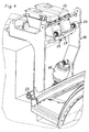
- One embodiment of the invention is described in greater detail with reference to the accompanying drawings in which:-
- Fig. 1
- shows a perspective view of a driver's cab linked with a vehicle frame on top of the vehicle frame;
- Fig. 2
- shows a lateral view of the driver's cab according to Fig. 1;
- Fig. 3
- shows a perspective view of the front wall of the driver's cab and part of a cab support frame associated with the vehicle and;
- Fig. 4
- shows a further -perspective view of the support frame associated with the vehicle.
- In the drawing, an agricultural tractor has a main frame 1 having a
driving area 2 with a combustion engine, atransmission area 3 as well as right hand side and left hand side axle trunnions 4 for the rear wheels of the vehicle which are not shown in the figures. - Above the
transmission area 3 on the vehicle frame a driver'scab 5 is located. The driver's cab consists of a frame work of special section tubes that determine the strength of the cab. In abottom area 6, the special section tubes form a rectangle with spring/damper-elements 7 located at the rear corner areas. The driver's cab is supported on the axle trunnions 4 via the spring/damper-elements 7. The spring/damper-elements 7 are inclined with respect to each other, in order to provide stabilizing lateral forces acting upon the driver'scab 5 from the vehicle frame 1. Thefront wall 8 of the driver'scab 5 is bordered by a lowerspecial section tube 9, that is also part of thebottom area 6 of the cab. An upperspecial section tube 10 that is orientated in parallel to the lowerspecial section tube 9 andspecial section tubes 11 orientated in a vertical direction are connected to form a closed frame which constitutes thefront wall 8. - In front of the
front wall 8 there are located twoframe components frame components special section tube 9. Theframe components cab 5. Approximately at their mid-height position the twoframe components holding device 14 for a single spring/damper-element 15. The driver'scab 5 is at the front supported from the vehicle frame 1 via the aforementioned spring/damper-element 15. - In order to provide a guidance for the driver's
cab 5 in a longitudinal direction and in a transverse direction as well as to limit rolling movements and pitching movements of the driver's cab, the driver's cab is in the centre of the cab linked with a vertical support frame 18 (best seen in Figure 4) by a linkingconfiguration 16 and an additionalupper link 17 located above the linkingconfiguration 16. Thevertical support frame 18 is rigidly connected with the vehicle frame 1 and is also used as a holding device for different components, for example awater container 19, a control unit for the engine and other items. Because thevertical frame 18 is located between thedriving area 2 with the combustion engine and thefront wall 8 of the cab, thevertical frame 18 is additionally used as a bulkhead separating the combustion engine from the driver'scab 5. - The linking
configuration 16 provides the guidance of the driver'scab 5 in longitudinal and transverse direction of the vehicle as well the limitation of rolling movements, whereas the additionalupper link 17 is essentially used for a limitation of pitching movements of the driver'scab 5. However, theupper link 17 also controls, together with the linkingconfiguration 16, the rolling movement of the driver'scab 5. - The linking
configuration 16 is built as a unit with a high torsional stiffness. The linkingconfiguration 16 consists of atube 20 extending in a transverse direction of the cab with a length that corresponds approximately with the width of thedriving area 2.Links 21 orientated in longitudinal direction of the vehicle are welded on the ends oftube 20. At the ends oflinks 21pivoting joints 22 associated with the cab andpivoting joints 23 associated with the frame are located. Thejoints 22 associated with the cab are linked in the region of thebottom area 6 of the driver'scab 5 with theframe components joints 22 associated with the cab correlates approximately with half of the width of thefront wall 8 of the driver'scab 5 in order to provide a broad supporting base for the linkingconfiguration 16 on the driver'scab 5. - If the agricultural tractor is ready for action the
driving area 2 is surrounded by an engine cover (not shown), which overlaps theframe 18 immediately in front of thefront wall 8. In order to accommodate the linkingconfiguration 16 at least to a large extend out of sight and to protect it against the weather, the distance between the pivotingjoints 23 associated with the vehicle frame is limited to the width of the drivingarea 2. The effective length of the linkingconfiguration 16 in longitudinal direction, (i.e. the distance between thejoints 22 and 23), is chosen as being approximately a quarter of the width of thefront wall 8 in order to keep the required space in longitudinal direction of the vehicle small. - The
additional link 17 is essentially T-shaped and connected with at theframe components joints 24 that are laterally spaced. In the area associated with the vehicle frame thelink 17 is supported fromframe 18 via one single pivoting joint 25, in order to control the pitching movements of the driver's cab resulting from accelerating and decelerating actions of the vehicle. Accordingly the distance of thejoints 24 associated with the cab from each other corresponds approximately to a quarter of the width of thefront wall 8 of the driver'scab 5. The effective length oflink 17, (i.e. the distance betweenjoints 24 and 25) corresponds to the length of the linkingconfiguration 16. - In order to avoid a penetration of
link 17 into the interior of the driver'scab 5 in case of an accident, thelink 17 includes a predetermined bucklingpoint 26. The predetermined bucklingpoint 26 is realized by anglingpart 27 which carries joints 24 at approximately 120° with respect to the part carrying the joint 25. For a determination of the angle of the angled part, the resulting elasticity of theupper link 17 in longitudinal direction of the vehicle and its effect on the control of the cab should be considered.
Claims (8)
- A utility vehicle, such as an agricultural tractor, with a driver's cab, that is suspended with respect to a vehicle frame (1) by elastic means and guided relatively with respect to the vehicle frame by links, the links being linked with the driver's cab approximately in the bottom area thereof and being orientated in the longitudinal direction of the vehicle, wherein a rear portion of the driver's cab (5) is supported by two laterally spaced spring/damper-elements (7) and a front portion of the driver's cab (5) is supported by one single spring/damper-element located approximately centrally in front of a front wall (8) of the driver's cab (5), and a linking configuration (16) is provided located centrally in front of the front wall (8), the linking configuration comprising two first links (21) that are laterally spaced and linked with each other to form a rigid unit, the links having pivoting joints (22) associated with the cab and pivoting joints (23) associated with the vehicle frame.
- A vehicle according to claim 1, wherein the lateral distance between the pivoting joints (22) of the first links (21) with the cab approximates to half of the width of the front wall (8) of the driver's cab (5) which in turn approximates to double the effective length of the first links (21).
- A vehicle according to claim 1 or 2, wherein the lateral distance between the pivoting joints (23) of the first links (21) and the vehicle frame (1) is smaller than the lateral distance between the pivoting joints (22) between the first links (21) and the diver's cab (5).
- A vehicle according to claim 1, wherein an additional link (17) pivotally supported by the vehicle frame (1) is located centrally in front of the front wall (8) in a plane that extends approximately through the centre of gravity (S) of the driver's cab (5), the additional link (17) being connected with the driver's cab (5) by two laterally spaced pivoting joints (24).
- A vehicle according to claim 4, wherein the lateral distance between the pivoting joints (24) of the additional link (17) with the cab is the same as or smaller than the lateral distance between the pivoting joints (22) of the first links (21) with the cab.
- A vehicle according to claims 4 or 5, wherein the length of the additional link (17) in longitudinal direction is variable by means of an elastic deformation.
- A vehicle according to claim 6, wherein the additional link (17) is angled with an angle of at least 90° for providing a predetermined buckling point (26).
- A vehicle according to anyone of claims 1 to 7, wherein the pivoting joints (23, 25) of the first links (21) and the additional link (17) with the vehicle are carried on a support frame (18), positioned between an engine (2) of the vehicle located in front of the driver's cab (5) and the front wall (8) of the driver's cab (5).
Applications Claiming Priority (1)
| Application Number | Priority Date | Filing Date | Title |
|---|---|---|---|
| GB0422217A GB2418897B (en) | 2004-10-06 | 2004-10-06 | Utility vehicle with suspended driver's cab |
Publications (3)
| Publication Number | Publication Date |
|---|---|
| EP1645494A2 true EP1645494A2 (en) | 2006-04-12 |
| EP1645494A3 EP1645494A3 (en) | 2008-01-16 |
| EP1645494B1 EP1645494B1 (en) | 2009-11-11 |
Family
ID=33428185
Family Applications (1)
| Application Number | Title | Priority Date | Filing Date |
|---|---|---|---|
| EP05020904A Expired - Lifetime EP1645494B1 (en) | 2004-10-06 | 2005-09-26 | Utility vehicle with suspended driver's cab |
Country Status (3)
| Country | Link |
|---|---|
| EP (1) | EP1645494B1 (en) |
| DE (1) | DE602005017553D1 (en) |
| GB (1) | GB2418897B (en) |
Cited By (15)
| Publication number | Priority date | Publication date | Assignee | Title |
|---|---|---|---|---|
| US8186475B2 (en) | 2010-05-12 | 2012-05-29 | Metalcraft Of Mayville, Inc. | Suspended operator platform |
| RU2494907C2 (en) * | 2010-09-01 | 2013-10-10 | КЛААС Трактор САС | Agricultural vehicle cab suspension |
| US8820456B2 (en) | 2008-06-11 | 2014-09-02 | Voltra Oy Ab | Cab suspensions |
| US9499204B1 (en) | 2015-05-05 | 2016-11-22 | The Toro Company | Suspension system and ride-on grounds maintenance vehicle incorporating same |
| WO2017016774A1 (en) | 2015-07-30 | 2017-02-02 | Zf Friedrichshafen Ag | Cab support arrangement for a utility vehicle |
| CN106458265A (en) * | 2014-06-26 | 2017-02-22 | 洋马株式会社 | Work vehicle |
| US9821689B2 (en) | 2016-01-06 | 2017-11-21 | Exmark Manufacturing Company, Incorporated | Operator platform suspension system for turf maintenance vehicle |
| CN107953935A (en) * | 2017-11-24 | 2018-04-24 | 中联重机股份有限公司 | A kind of tractor |
| US10597092B2 (en) | 2017-12-21 | 2020-03-24 | The Toro Company | Work vehicle and suspension system for use with same |
| US10717475B2 (en) | 2018-12-03 | 2020-07-21 | Deere & Company | Operator station suspension isolation system |
| US10793204B2 (en) | 2018-12-03 | 2020-10-06 | Deere & Company | Operator station suspension isolation system |
| US11173969B2 (en) | 2017-05-01 | 2021-11-16 | Agco Corporation | Four-point cab suspension system |
| US11203383B2 (en) | 2017-12-21 | 2021-12-21 | Deere & Company | Operator station suspension system |
| US11772716B1 (en) | 2022-03-14 | 2023-10-03 | Deere & Company | Suspension system for an operator station of a work vehicle |
| CN116873057A (en) * | 2023-08-08 | 2023-10-13 | 东风柳州汽车有限公司 | Cab suspension system and commercial vehicle |
Families Citing this family (1)
| Publication number | Priority date | Publication date | Assignee | Title |
|---|---|---|---|---|
| DE102015221189B4 (en) | 2015-10-29 | 2025-09-18 | Schaeffler Technologies AG & Co. KG | Cab suspension and use of a cab suspension |
Family Cites Families (7)
| Publication number | Priority date | Publication date | Assignee | Title |
|---|---|---|---|---|
| DK106071A (en) * | 1963-09-12 | |||
| FR2456263A1 (en) * | 1979-05-09 | 1980-12-05 | Unic Sa | SUSPENSION DEVICE, ESPECIALLY FROM A CAB, ON THE CHASSIS OF A VEHICLE |
| US5984036A (en) * | 1996-06-04 | 1999-11-16 | Hitachi Construction Machinery Co. Ltd. | Work machine with operator's cabin |
| GB9719577D0 (en) * | 1997-09-16 | 1997-11-19 | Hendrickson Europ Limited | Suspension systems |
| EP0994009B1 (en) * | 1998-10-16 | 2004-12-01 | Same Deutz-Fahr Group Spa | An agricultural machine with a self-leveling cab |
| DE10232909A1 (en) * | 2002-07-19 | 2004-01-29 | Deere & Company, Moline | Cabin storage for a vehicle cabin |
| WO2004018243A2 (en) * | 2002-08-21 | 2004-03-04 | Delphi Technologies, Inc. | Controlled truck cab suspension |
-
2004
- 2004-10-06 GB GB0422217A patent/GB2418897B/en not_active Expired - Fee Related
-
2005
- 2005-09-26 DE DE602005017553T patent/DE602005017553D1/en active Active
- 2005-09-26 EP EP05020904A patent/EP1645494B1/en not_active Expired - Lifetime
Cited By (20)
| Publication number | Priority date | Publication date | Assignee | Title |
|---|---|---|---|---|
| US8820456B2 (en) | 2008-06-11 | 2014-09-02 | Voltra Oy Ab | Cab suspensions |
| US8186475B2 (en) | 2010-05-12 | 2012-05-29 | Metalcraft Of Mayville, Inc. | Suspended operator platform |
| RU2494907C2 (en) * | 2010-09-01 | 2013-10-10 | КЛААС Трактор САС | Agricultural vehicle cab suspension |
| CN106458265A (en) * | 2014-06-26 | 2017-02-22 | 洋马株式会社 | Work vehicle |
| EP3162669A4 (en) * | 2014-06-26 | 2018-03-21 | Yanmar Co., Ltd. | Work vehicle |
| US9499204B1 (en) | 2015-05-05 | 2016-11-22 | The Toro Company | Suspension system and ride-on grounds maintenance vehicle incorporating same |
| DE102015214456A1 (en) | 2015-07-30 | 2017-02-02 | Deere & Company | Cabin storage arrangement for a commercial vehicle |
| WO2017016774A1 (en) | 2015-07-30 | 2017-02-02 | Zf Friedrichshafen Ag | Cab support arrangement for a utility vehicle |
| CN107848581A (en) * | 2015-07-30 | 2018-03-27 | Zf腓特烈斯哈芬股份公司 | Cabin mount component for commercial car |
| CN107848581B (en) * | 2015-07-30 | 2020-06-30 | Zf腓特烈斯哈芬股份公司 | Cab bearing arrangement for a commercial vehicle |
| US10549796B2 (en) | 2015-07-30 | 2020-02-04 | Zf Friedrichshafen Ag | Cab support arrangement for a utility vehicle |
| US9821689B2 (en) | 2016-01-06 | 2017-11-21 | Exmark Manufacturing Company, Incorporated | Operator platform suspension system for turf maintenance vehicle |
| US11173969B2 (en) | 2017-05-01 | 2021-11-16 | Agco Corporation | Four-point cab suspension system |
| CN107953935A (en) * | 2017-11-24 | 2018-04-24 | 中联重机股份有限公司 | A kind of tractor |
| US10597092B2 (en) | 2017-12-21 | 2020-03-24 | The Toro Company | Work vehicle and suspension system for use with same |
| US11203383B2 (en) | 2017-12-21 | 2021-12-21 | Deere & Company | Operator station suspension system |
| US10717475B2 (en) | 2018-12-03 | 2020-07-21 | Deere & Company | Operator station suspension isolation system |
| US10793204B2 (en) | 2018-12-03 | 2020-10-06 | Deere & Company | Operator station suspension isolation system |
| US11772716B1 (en) | 2022-03-14 | 2023-10-03 | Deere & Company | Suspension system for an operator station of a work vehicle |
| CN116873057A (en) * | 2023-08-08 | 2023-10-13 | 东风柳州汽车有限公司 | Cab suspension system and commercial vehicle |
Also Published As
| Publication number | Publication date |
|---|---|
| EP1645494A3 (en) | 2008-01-16 |
| GB0422217D0 (en) | 2004-11-03 |
| GB2418897A (en) | 2006-04-12 |
| GB2418897B (en) | 2008-02-06 |
| DE602005017553D1 (en) | 2009-12-24 |
| EP1645494B1 (en) | 2009-11-11 |
Similar Documents
| Publication | Publication Date | Title |
|---|---|---|
| EP1645494B1 (en) | Utility vehicle with suspended driver's cab | |
| US11104384B2 (en) | Side-by-side all terrain vehicle | |
| US9266452B2 (en) | Vehicle vibration device for vehicle seats or vehicle cabs | |
| US10549796B2 (en) | Cab support arrangement for a utility vehicle | |
| US10118643B2 (en) | Front sub-frame structure | |
| EP0640049B1 (en) | Modular cab and sleeper structural assembly for a truck-tractor vehicle | |
| US11203383B2 (en) | Operator station suspension system | |
| US7770964B2 (en) | Spring strut mounting | |
| US10494039B2 (en) | Multiple degree of freedom cab suspension system | |
| US5368118A (en) | Torsion bar suspension for operator's platform | |
| US6206121B1 (en) | Vehicle with a resiliently suspended cab part, particularly a driver's cab | |
| US3948341A (en) | Tilt cab truck | |
| US8534412B2 (en) | Multipurpose utility vehicle | |
| EP3626586B1 (en) | Suspension sub frame structure | |
| GB1598639A (en) | Vehicle with a drivers cab | |
| CN100579851C (en) | Suspension with scissor telescoping mechanism | |
| JP2009511333A (en) | Vehicle equipped with a rear end mounting battery box | |
| EP0882641B1 (en) | Agricultural vehicle with cab and cab suspension | |
| NL193060C (en) | Truck with a cab consisting of at least two parts. | |
| EP0213098A2 (en) | Arrangement for suspending a forwardly tippable cab on a vehicle | |
| GB2418183A (en) | Vehicle with tiltable cab mounted on chassis | |
| US9022399B2 (en) | Vehicle cab suspension device | |
| JP2019209741A (en) | Work vehicle | |
| EP3003833B2 (en) | A truck chassis, a truck cab and a truck comprising said chassis and cab | |
| WO2010136095A1 (en) | Vibration-isolated wheel axle for motor vehicle |
Legal Events
| Date | Code | Title | Description |
|---|---|---|---|
| PUAI | Public reference made under article 153(3) epc to a published international application that has entered the european phase |
Free format text: ORIGINAL CODE: 0009012 |
|
| AK | Designated contracting states |
Kind code of ref document: A2 Designated state(s): AT BE BG CH CY CZ DE DK EE ES FI FR GB GR HU IE IS IT LI LT LU LV MC NL PL PT RO SE SI SK TR |
|
| AX | Request for extension of the european patent |
Extension state: AL BA HR MK YU |
|
| PUAL | Search report despatched |
Free format text: ORIGINAL CODE: 0009013 |
|
| AK | Designated contracting states |
Kind code of ref document: A3 Designated state(s): AT BE BG CH CY CZ DE DK EE ES FI FR GB GR HU IE IS IT LI LT LU LV MC NL PL PT RO SE SI SK TR |
|
| AX | Request for extension of the european patent |
Extension state: AL BA HR MK YU |
|
| 17P | Request for examination filed |
Effective date: 20080716 |
|
| 17Q | First examination report despatched |
Effective date: 20080818 |
|
| AKX | Designation fees paid |
Designated state(s): DE FR GB IT |
|
| GRAP | Despatch of communication of intention to grant a patent |
Free format text: ORIGINAL CODE: EPIDOSNIGR1 |
|
| GRAS | Grant fee paid |
Free format text: ORIGINAL CODE: EPIDOSNIGR3 |
|
| GRAA | (expected) grant |
Free format text: ORIGINAL CODE: 0009210 |
|
| AK | Designated contracting states |
Kind code of ref document: B1 Designated state(s): DE FR GB IT |
|
| REG | Reference to a national code |
Ref country code: GB Ref legal event code: FG4D |
|
| REF | Corresponds to: |
Ref document number: 602005017553 Country of ref document: DE Date of ref document: 20091224 Kind code of ref document: P |
|
| REG | Reference to a national code |
Ref country code: DE Ref legal event code: R096 Ref document number: 602005017553 Country of ref document: DE Effective date: 20091224 |
|
| PLBE | No opposition filed within time limit |
Free format text: ORIGINAL CODE: 0009261 |
|
| STAA | Information on the status of an ep patent application or granted ep patent |
Free format text: STATUS: NO OPPOSITION FILED WITHIN TIME LIMIT |
|
| 26N | No opposition filed |
Effective date: 20100812 |
|
| REG | Reference to a national code |
Ref country code: DE Ref legal event code: R097 Ref document number: 602005017553 Country of ref document: DE Effective date: 20100812 |
|
| REG | Reference to a national code |
Ref country code: FR Ref legal event code: PLFP Year of fee payment: 12 |
|
| REG | Reference to a national code |
Ref country code: FR Ref legal event code: PLFP Year of fee payment: 13 |
|
| REG | Reference to a national code |
Ref country code: FR Ref legal event code: PLFP Year of fee payment: 14 |
|
| PGFP | Annual fee paid to national office [announced via postgrant information from national office to epo] |
Ref country code: IT Payment date: 20180921 Year of fee payment: 14 |
|
| PGFP | Annual fee paid to national office [announced via postgrant information from national office to epo] |
Ref country code: GB Payment date: 20180919 Year of fee payment: 14 |
|
| PG25 | Lapsed in a contracting state [announced via postgrant information from national office to epo] |
Ref country code: IT Free format text: LAPSE BECAUSE OF NON-PAYMENT OF DUE FEES Effective date: 20190926 |
|
| GBPC | Gb: european patent ceased through non-payment of renewal fee |
Effective date: 20190926 |
|
| PG25 | Lapsed in a contracting state [announced via postgrant information from national office to epo] |
Ref country code: GB Free format text: LAPSE BECAUSE OF NON-PAYMENT OF DUE FEES Effective date: 20190926 |
|
| P01 | Opt-out of the competence of the unified patent court (upc) registered |
Effective date: 20230518 |
|
| PGFP | Annual fee paid to national office [announced via postgrant information from national office to epo] |
Ref country code: DE Payment date: 20240918 Year of fee payment: 20 |
|
| PGFP | Annual fee paid to national office [announced via postgrant information from national office to epo] |
Ref country code: FR Payment date: 20240924 Year of fee payment: 20 |
|
| REG | Reference to a national code |
Ref country code: DE Ref legal event code: R071 Ref document number: 602005017553 Country of ref document: DE |